WO2016063628A1 - 電気音響変換装置 - Google Patents
電気音響変換装置 Download PDFInfo
- Publication number
- WO2016063628A1 WO2016063628A1 PCT/JP2015/074559 JP2015074559W WO2016063628A1 WO 2016063628 A1 WO2016063628 A1 WO 2016063628A1 JP 2015074559 W JP2015074559 W JP 2015074559W WO 2016063628 A1 WO2016063628 A1 WO 2016063628A1
- Authority
- WO
- WIPO (PCT)
- Prior art keywords
- piezoelectric element
- diaphragm
- laminated piezoelectric
- electrode layer
- electrode
- Prior art date
- Legal status (The legal status is an assumption and is not a legal conclusion. Google has not performed a legal analysis and makes no representation as to the accuracy of the status listed.)
- Ceased
Links
Images






Classifications
-
- H—ELECTRICITY
- H10—SEMICONDUCTOR DEVICES; ELECTRIC SOLID-STATE DEVICES NOT OTHERWISE PROVIDED FOR
- H10N—ELECTRIC SOLID-STATE DEVICES NOT OTHERWISE PROVIDED FOR
- H10N30/00—Piezoelectric or electrostrictive devices
- H10N30/80—Constructional details
- H10N30/87—Electrodes or interconnections, e.g. leads or terminals
- H10N30/871—Single-layered electrodes of multilayer piezoelectric or electrostrictive devices, e.g. internal electrodes
-
- H—ELECTRICITY
- H04—ELECTRIC COMMUNICATION TECHNIQUE
- H04R—LOUDSPEAKERS, MICROPHONES, GRAMOPHONE PICK-UPS OR LIKE ACOUSTIC ELECTROMECHANICAL TRANSDUCERS; ELECTRIC HEARING AIDS; PUBLIC ADDRESS SYSTEMS
- H04R17/00—Piezoelectric transducers; Electrostrictive transducers
-
- H—ELECTRICITY
- H04—ELECTRIC COMMUNICATION TECHNIQUE
- H04R—LOUDSPEAKERS, MICROPHONES, GRAMOPHONE PICK-UPS OR LIKE ACOUSTIC ELECTROMECHANICAL TRANSDUCERS; ELECTRIC HEARING AIDS; PUBLIC ADDRESS SYSTEMS
- H04R7/00—Diaphragms for electromechanical transducers; Cones
- H04R7/02—Diaphragms for electromechanical transducers; Cones characterised by the construction
- H04R7/04—Plane diaphragms
-
- B—PERFORMING OPERATIONS; TRANSPORTING
- B06—GENERATING OR TRANSMITTING MECHANICAL VIBRATIONS IN GENERAL
- B06B—METHODS OR APPARATUS FOR GENERATING OR TRANSMITTING MECHANICAL VIBRATIONS OF INFRASONIC, SONIC, OR ULTRASONIC FREQUENCY, e.g. FOR PERFORMING MECHANICAL WORK IN GENERAL
- B06B1/00—Methods or apparatus for generating mechanical vibrations of infrasonic, sonic, or ultrasonic frequency
- B06B1/02—Methods or apparatus for generating mechanical vibrations of infrasonic, sonic, or ultrasonic frequency making use of electrical energy
- B06B1/06—Methods or apparatus for generating mechanical vibrations of infrasonic, sonic, or ultrasonic frequency making use of electrical energy operating with piezoelectric effect or with electrostriction
-
- B—PERFORMING OPERATIONS; TRANSPORTING
- B06—GENERATING OR TRANSMITTING MECHANICAL VIBRATIONS IN GENERAL
- B06B—METHODS OR APPARATUS FOR GENERATING OR TRANSMITTING MECHANICAL VIBRATIONS OF INFRASONIC, SONIC, OR ULTRASONIC FREQUENCY, e.g. FOR PERFORMING MECHANICAL WORK IN GENERAL
- B06B1/00—Methods or apparatus for generating mechanical vibrations of infrasonic, sonic, or ultrasonic frequency
- B06B1/02—Methods or apparatus for generating mechanical vibrations of infrasonic, sonic, or ultrasonic frequency making use of electrical energy
- B06B1/06—Methods or apparatus for generating mechanical vibrations of infrasonic, sonic, or ultrasonic frequency making use of electrical energy operating with piezoelectric effect or with electrostriction
- B06B1/0607—Methods or apparatus for generating mechanical vibrations of infrasonic, sonic, or ultrasonic frequency making use of electrical energy operating with piezoelectric effect or with electrostriction using multiple elements
- B06B1/0611—Methods or apparatus for generating mechanical vibrations of infrasonic, sonic, or ultrasonic frequency making use of electrical energy operating with piezoelectric effect or with electrostriction using multiple elements in a pile
-
- H—ELECTRICITY
- H02—GENERATION; CONVERSION OR DISTRIBUTION OF ELECTRIC POWER
- H02N—ELECTRIC MACHINES NOT OTHERWISE PROVIDED FOR
- H02N2/00—Electric machines in general using piezoelectric effect, electrostriction or magnetostriction
-
- H—ELECTRICITY
- H10—SEMICONDUCTOR DEVICES; ELECTRIC SOLID-STATE DEVICES NOT OTHERWISE PROVIDED FOR
- H10N—ELECTRIC SOLID-STATE DEVICES NOT OTHERWISE PROVIDED FOR
- H10N30/00—Piezoelectric or electrostrictive devices
- H10N30/01—Manufacture or treatment
- H10N30/06—Forming electrodes or interconnections, e.g. leads or terminals
- H10N30/063—Forming interconnections, e.g. connection electrodes of multilayered piezoelectric or electrostrictive parts
-
- H—ELECTRICITY
- H10—SEMICONDUCTOR DEVICES; ELECTRIC SOLID-STATE DEVICES NOT OTHERWISE PROVIDED FOR
- H10N—ELECTRIC SOLID-STATE DEVICES NOT OTHERWISE PROVIDED FOR
- H10N30/00—Piezoelectric or electrostrictive devices
- H10N30/01—Manufacture or treatment
- H10N30/06—Forming electrodes or interconnections, e.g. leads or terminals
- H10N30/067—Forming single-layered electrodes of multilayered piezoelectric or electrostrictive parts
-
- H—ELECTRICITY
- H10—SEMICONDUCTOR DEVICES; ELECTRIC SOLID-STATE DEVICES NOT OTHERWISE PROVIDED FOR
- H10N—ELECTRIC SOLID-STATE DEVICES NOT OTHERWISE PROVIDED FOR
- H10N30/00—Piezoelectric or electrostrictive devices
- H10N30/30—Piezoelectric or electrostrictive devices with mechanical input and electrical output, e.g. functioning as generators or sensors
- H10N30/302—Sensors
-
- H—ELECTRICITY
- H10—SEMICONDUCTOR DEVICES; ELECTRIC SOLID-STATE DEVICES NOT OTHERWISE PROVIDED FOR
- H10N—ELECTRIC SOLID-STATE DEVICES NOT OTHERWISE PROVIDED FOR
- H10N30/00—Piezoelectric or electrostrictive devices
- H10N30/50—Piezoelectric or electrostrictive devices having a stacked or multilayer structure
-
- H—ELECTRICITY
- H10—SEMICONDUCTOR DEVICES; ELECTRIC SOLID-STATE DEVICES NOT OTHERWISE PROVIDED FOR
- H10N—ELECTRIC SOLID-STATE DEVICES NOT OTHERWISE PROVIDED FOR
- H10N30/00—Piezoelectric or electrostrictive devices
- H10N30/50—Piezoelectric or electrostrictive devices having a stacked or multilayer structure
- H10N30/501—Piezoelectric or electrostrictive devices having a stacked or multilayer structure having a non-rectangular cross-section in a plane parallel to the stacking direction, e.g. polygonal or trapezoidal in side view
-
- H—ELECTRICITY
- H10—SEMICONDUCTOR DEVICES; ELECTRIC SOLID-STATE DEVICES NOT OTHERWISE PROVIDED FOR
- H10N—ELECTRIC SOLID-STATE DEVICES NOT OTHERWISE PROVIDED FOR
- H10N30/00—Piezoelectric or electrostrictive devices
- H10N30/80—Constructional details
- H10N30/87—Electrodes or interconnections, e.g. leads or terminals
Definitions
- the present invention relates to an electroacoustic transducer provided with a polygonal laminated piezoelectric element and a circular diaphragm.
- An electroacoustic transducer including a laminated piezoelectric element and a diaphragm on which the laminated piezoelectric element is disposed is well known.
- the laminated piezoelectric element is deformed by the electric signal, and the diaphragm is vibrated by the deformation, and the electroacoustic transducer generates an audible wave.
- the diaphragm is often circular. This is because the rectangular diaphragm is irregularly deformed during vibration and the sound quality is likely to deteriorate.
- a polygonal laminated piezoelectric element is advantageous in terms of cost because it has a higher material yield than a circular laminated piezoelectric element and the piezoelectric material is expensive.
- FIG. 15 shows a piezoelectric acoustic component 61 described in Patent Document 1 among few conventional technologies.
- the piezoelectric acoustic component 61 includes a rectangular piezoelectric plate 62 and a disk-shaped metal plate 63 on which the piezoelectric plate 62 is disposed.
- the piezoelectric acoustic component 61 is fitted into a ring-shaped case 64 having a concentric step on the inner peripheral side, and is incorporated into a portable acoustic device such as a mobile phone or a headphone.
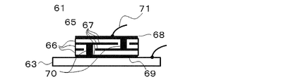
- FIG. 16 shows the internal structure of the laminated piezoelectric element 65 described in Patent Document 2.
- the electrode layer 67 includes a first surface electrode layer 68 formed on the first surface of the laminated piezoelectric element 65 opposite to the surface in contact with the metal plate 63, and a side opposite to the first surface (the metal plate 63 and It includes a second surface electrode layer 69 formed on the second surface on the contact side.
- the electrode layers 67 including the first surface electrode layer 68 and the second surface electrode layer 69 are connected to every other pair of connection electrodes 70 having different polarities.
- the number of piezoelectric layers 66 is an odd number, and the first surface electrode layer 68 and the second surface electrode layer 69 are connected to a pair of connection electrodes 70 having different polarities.
- the connection electrode 70 is formed by a through hole.
- a lead wire 71 is soldered to the first surface electrode layer 68.
- the laminated piezoelectric element 65 is disposed on a disk-shaped metal plate 63 so that the second surface is in contact with it, and the second surface electrode layer 69 and the metal plate 63 are electrically connected. An electrical signal is applied to the laminated piezoelectric element 65 via the lead wire 71 and the metal plate 63.
- the laminated piezoelectric element 65 is deformed, and the diaphragm 63 is vibrated by this deformation, and the electroacoustic transducer 61 generates an audible wave.
- the contact area between the laminated piezoelectric element and the diaphragm is smaller than a combination of similar shapes. Since the force with which the laminated piezoelectric element vibrates the diaphragm is reduced, the sound pressure is reduced.
- the present invention has been made in view of the above circumstances, and an object thereof is to provide an electroacoustic transducer capable of obtaining sound pressure equivalent to that of a circular multilayer piezoelectric element even when a polygonal multilayer piezoelectric element is used. To do.
- One aspect of the present invention is A laminated piezoelectric element in which piezoelectric layers and electrode layers are alternately laminated, and the piezoelectric layer is disposed between at least a pair of electrode layers having different polarities; A vibration plate on which the laminated piezoelectric element is disposed; The laminated piezoelectric element is polygonal when viewed from the lamination direction, The surface of the diaphragm on which the laminated piezoelectric element is disposed is circular, Of the piezoelectric layers sandwiched between the at least one pair of electrode layers, the total volume (V) of the effective layers projected from the stacking direction and overlapping the at least one pair of electrode layers satisfies the following condition:
- the present invention relates to an electroacoustic transducer. 0.2 ⁇ R 2 ⁇ ts ⁇ V ⁇ 2.0 ⁇ R 2 ⁇ ts (Where ⁇ is the circumference ratio, R is the radius of the diaphragm, and ts is the thickness of the diaphragm)
- the laminated piezoelectric element an effective layer that is a portion where two electrode layers having different polarities projected from the stacking direction overlap among piezoelectric layers sandwiched between a pair of electrode layers having different polarities is deformed. This deformation is transmitted to the diaphragm, and the electroacoustic transducer generates an audible wave.
- the multilayer piezoelectric element when the total volume (V) of the effective layers satisfies the above formula, the multilayer piezoelectric element has a sufficiently large force to vibrate the diaphragm, and a polygonal multilayer piezoelectric element can be used. Sound pressure equivalent to that of a circular laminated piezoelectric element can be obtained.
- the at least one pair of electrode layers includes a first electrode layer and a second electrode layer having different polarities, and the first electrode layer is a first side surface formed on one side surface of the multilayer piezoelectric element.
- the second electrode layer is preferably connected to a second side electrode formed on a side surface different from the side surface on which the first side electrode is formed.
- the circular diaphragm may be greatly deformed in a specific region, particularly a concentric region at a specific distance from the center of the diaphragm. If there is a connection electrode between the electrode layers in this region, stress due to deformation may concentrate and break. However, since the side electrode has a width from the center of the circular diaphragm, even if the side electrode is broken in a specific region, the connection in another region is maintained. Therefore, stable sound pressure and sound quality are expected to be maintained.
- the first electrode layer preferably includes an electrode layer formed on the surface of the laminated piezoelectric element opposite to the surface in contact with the vibration plate.
- the connection between the electrode layers is not through-holes but side electrodes, no stress remains in the laminated piezoelectric element. For this reason, even if the lead wire is soldered to the electrode layer formed on the surface of the laminated piezoelectric element opposite to the surface in contact with the diaphragm, the laminated piezoelectric element can be prevented from being damaged by thermal shock.
- the multilayer piezoelectric element is preferably square when viewed from the stacking direction. Since the symmetry of the shape of the multilayer piezoelectric element approaches a circular shape, the sound quality approaches that of a circular multilayer piezoelectric element.
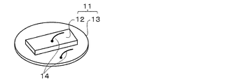
- the external appearance of the electroacoustic transducer which concerns on 1st Embodiment is shown.
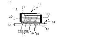
- the internal structure of the electroacoustic transducer which concerns on 1st Embodiment is shown.
- stacking and external appearance of the lamination piezoelectric element in 1st Embodiment are shown.
- the stability of the connection of the side electrode in 1st Embodiment is shown.
- the effective layer of the laminated piezoelectric element in 1st Embodiment is shown.
- the dimension of the circular diaphragm of the electroacoustic transducer which concerns on 1st Embodiment, and a polygonal laminated piezoelectric element is shown.
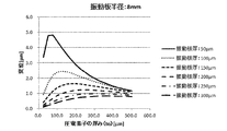
- the displacement amount of the center part of the diaphragm when the thickness of the diaphragm and the thickness of the effective layer of the laminated piezoelectric element are changed is shown.
- the amount of displacement of the center part of the diaphragm when the thickness of the diaphragm and the thickness of the effective layer of the laminated piezoelectric element are changed is shown.
- the relative displacement amount of the center part of the diaphragm when the thickness of the diaphragm and the thickness of the effective layer of the laminated piezoelectric element are changed is shown.
- the comparison of the sound pressure characteristic of the electroacoustic transducer provided with the square laminated piezoelectric element which concerns on 1st Embodiment, and the sound pressure characteristic of the electroacoustic transducer provided with the circular laminated piezoelectric element is shown.
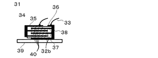
- the internal structure of the electroacoustic transducer which concerns on 2nd Embodiment is shown.
- the internal structure of the electroacoustic transducer which concerns on 3rd Embodiment is shown.
- the external appearance of the electroacoustic transducer which concerns on 4th Embodiment is shown.
- the external appearance of the electroacoustic transducer which concerns on 5th Embodiment is shown.
- the external appearance of the conventional piezoelectric acoustic component is shown.
- the internal structure of the conventional laminated piezoelectric element is shown.
- the shape of the laminated piezoelectric element and the diaphragm is expressed by the shape of the laminated piezoelectric element when viewed from the lamination direction and the shape of the diaphragm on the surface where the laminated piezoelectric element is arranged.
- the “circular laminated piezoelectric element” has a cylindrical shape as an actual laminated piezoelectric element, but is expressed as “circular” when viewed from the laminating direction for convenience.
- the “polygonal laminated piezoelectric element” is actually a polygonal column in the shape of a laminated piezoelectric element, but is expressed as a “polygon” when viewed from the lamination direction for convenience.
- the “circular diaphragm” is actually a cylinder, but for convenience, it is expressed by “circular” on the surface on which the laminated piezoelectric elements are arranged.
- FIG. 1 shows the appearance of an electroacoustic transducer 11 according to the first embodiment of the present invention.
- the electroacoustic transducer 11 includes a polygonal laminated piezoelectric element 12 and a circular diaphragm 13 on which the laminated piezoelectric element 12 is disposed.
- the laminated piezoelectric element 12 is arranged on one side of the diaphragm 13, but the laminated piezoelectric element 12 may be arranged on both sides of the diaphragm 13.
- the shape of the laminated piezoelectric element 12 includes a square, a rhombus, a trapezoid, a square, a rectangle, and a hexagon.
- the square means that
- a and b are the lengths of two orthogonal sides.
- the shape of the laminated piezoelectric element is a polygon (for example, a rectangle) other than a regular polygon (such as a square or a regular hexagon)
- the orientation of the laminated piezoelectric element 12 can be determined. Operations such as placement of the laminated piezoelectric element 12 on the diaphragm 13 and formation of electrodes on the laminated piezoelectric element 12 can be performed reliably, and variations in sound quality among the electroacoustic transducers 11 are reduced.
- the dimension (maximum length) of the laminated piezoelectric element 12 is 5.4 to 108 mm. If it is too small, production is difficult, and if it is large, cracks are likely to occur in the laminated piezoelectric element 12.
- the thickness of the laminated piezoelectric element is 0.03 to 0.2 mm (30 to 0.200 ⁇ m). If it is too small, production is difficult, and if it is large, deformation of the laminated piezoelectric element 12 is hindered.
- the radius of the diaphragm 13 is 3 to 60 mm. If it is too small, production is difficult, and if it is large, cracks are likely to occur in the laminated piezoelectric element 12 to be arranged.
- the thickness of the diaphragm 13 is desirably 0.05 to 0.5 mm, and more desirably 0.05 to 0.3 mm. If it is too thin, the strength will be weak, and if it is thick, vibration will be hindered.
- a metal can be used as the diaphragm 13. Examples of the metal include stainless steel (SUS) and 42 alloy. In this embodiment, 42 alloy was used, the diaphragm 13 had a radius of 5.55 mm and a thickness of 200 ⁇ m.
- a lead wire 14 is provided on the first surface of the laminated piezoelectric element 12 opposite to the surface in contact with the diaphragm 13 and the surface of the diaphragm 13 on which the laminated piezoelectric element 12 is disposed and not in contact with the laminated piezoelectric element 12. Is soldered. Since the laminated piezoelectric element 12 is polygonal, the area of the diaphragm 13 that is not in contact with the laminated piezoelectric element 12 is wider than when the laminated piezoelectric element 12 is circular. For this reason, it is easy to solder the lead wire 14 to the diaphragm 13.
- the diaphragm 13 is a metal, an electric signal is applied to the laminated piezoelectric element 12 via the lead wire 14 and the diaphragm 13.
- the laminated piezoelectric element 12 is deformed, and the diaphragm 13 is vibrated by the deformation, and the electroacoustic transducer 11 generates an audible wave.
- FIG. 2 shows the internal structure of the electroacoustic transducer 11 according to the first embodiment.
- piezoelectric layers 15 and electrode layers 16 are alternately laminated.
- a ferroelectric material such as lead zirconate titanate (PZT), barium titanate, alkali-containing perovskite, tungsten bronze, or the like is used.
- PZT lead zirconate titanate
- barium titanate alkali-containing perovskite
- tungsten bronze or the like
- the electrode layer 16 Ag / Pd, Pd, or the like can be used.
- the thickness of the electrode layer 16 is 1 to 5 ⁇ m. If it is too thin, the electrode layer 16 tends to be discontinuous, and if it is too thick, deformation of the laminated piezoelectric element 12 is hindered.
- PZT is used as the piezoelectric layer 15
- Ag / Pd is used as the electrode layer 16
- the electrode layer 16 is formed to have a thickness of 2
- the electrode layer 16 includes a first surface electrode layer 17 formed on the first surface of the laminated piezoelectric element 12 on the side opposite to the surface in contact with the diaphragm 13, and the laminated piezoelectric element 12 on the side in contact with the diaphragm 13.
- a second surface electrode layer 18 formed on the second surface and an internal electrode layer 19 formed inside the laminated piezoelectric element 12 are included.
- the electrode layer 16 includes two electrode layers having different polarities, and is referred to as a first electrode layer 16a and a second electrode layer 16b, respectively.
- the first electrode layer 16a and the second electrode layer 16b are disposed every other layer.
- the piezoelectric layer 15 is sandwiched between the first electrode layer 16a and the second electrode layer 16b.
- the number of piezoelectric layers 15 may be 2 to 10, but an odd number of 3 or more is preferable because the electrode layer 16 can be easily disposed. This is because the first and second surface electrode layers 17 and 18 can be formed as the first and second electrode layers 16a and 16b, respectively. In this embodiment, the number of piezoelectric layers 15 is five.
- the connection between the electrode layers will be described with reference to FIG.
- the first electrode layer 16 a (including the first surface electrode layer 17) is drawn out to one side surface of the laminated piezoelectric element 12.
- the first electrode layer 16a (including the first surface electrode layer 17) is connected to the first side electrode 20 formed on the extracted side surface.
- the second electrode layer 16b (including the second surface electrode layer 18) is different from the side surface on which the first side electrode is formed, for example, the side opposite to the side surface on which the first side electrode is formed. Pulled out to the side.
- the second electrode layer 16b (including the second surface electrode layer 18) is connected to the second side electrode 21 formed on the extracted side surface.
- the first and second side electrodes 20, 21 are formed by a known method. For example, a dip method or a sputtering method is used. In this embodiment, a sputtering method was used.
- the second surface electrode layer 18 contacts the vibration plate 13. Since the diaphragm 13 is a metal, both are electrically connected.
- a known method can be used to fix the laminated piezoelectric element 12. For example, even when an insulating adhesive such as a resin adhesive is used, the second surface electrode layer 18 has fine irregularities and is therefore electrically connected by being pressed against the diaphragm 13.
- the lead wire 14 is soldered to a region of the surface of the diaphragm 13 on which the first piezoelectric layer 12 of the multilayer piezoelectric element 12 and the multilayer piezoelectric element 12 are arranged and not in contact with the multilayer piezoelectric element 12.
- the electrical signal is applied to the laminated piezoelectric element 12 via the lead wire 14 and the diaphragm 13.
- the laminated piezoelectric element 12 is deformed, and the diaphragm 13 is vibrated by the deformation, and the electroacoustic transducer 11 generates an audible wave.
- the deformation of the polygonal laminated piezoelectric element 12 is large at the center, and the deformation becomes smaller as the apex of the polygon is approached.
- the circular vibration plate 13 also has a large amplitude at the center portion, and the amplitude decreases as it approaches the outer peripheral portion.
- the amplitude of the circular diaphragm 13 may increase in a specific region due to primary resonance or the like, for example, a concentric region 22 at a specific distance from the center P of the diaphragm 13 as shown by a broken line in FIG. is there. If there is a connection electrode between the electrode layers in this region, the stress is concentrated due to a large amplitude, and there is a risk of destruction.
- the first and second side electrodes 20, 21 may be destroyed in the region 23 that overlaps the concentric region 22 from the center P of the diaphragm 13.
- the connection is maintained in other regions even if the region 23 is destroyed. Therefore, stable sound pressure and sound quality are maintained.
- FIG. 5 shows a portion where the laminated piezoelectric element 12 is deformed when an electric signal is applied in the first embodiment.
- the multilayer piezoelectric element 12 is deformed by projecting from the stacking direction of the piezoelectric layer 15 sandwiched between two electrode layers (first electrode layer 16a and second electrode layer 16b) having different polarities. This is the portion where the electrode layer 16a and the second electrode layer 16b overlap (shaded area in FIG. 5), that is, the effective layer 24.
- the deformation of the effective layer 24 vibrates the diaphragm, and the electroacoustic transducer generates an audible wave.
- the laminated piezoelectric element 12 includes, in addition to the effective layer 24, a margin portion 25 (piezoelectric layer in a portion where electrodes of different polarities do not overlap) and the electrode layer 16 having a width of about 100 ⁇ m around the effective layer 24. Since the volume is smaller than that of the layer 24, the sound pressure is not substantially affected. When the total volume of the effective layer 24 is V, V can be approximated by measuring the dimensions of the laminated piezoelectric element.
- the present inventor found that the total effective volume (V) of the polygonal laminated piezoelectric element 12 is as follows: It was found that a sound pressure equivalent to that of a circular multilayer piezoelectric element can be obtained by satisfying the conditional expression (Formula 1). 0.2 ⁇ R 2 ⁇ ts ⁇ V ⁇ 2.0 ⁇ R 2 ⁇ ts (Formula 1) (Where ⁇ is the circumference ratio, R is the radius of the diaphragm, and ts is the thickness of the diaphragm)
- the radius of the circular diaphragm 13 is R
- the thickness of the diaphragm 13 is ts
- the diagonal length of the effective layer of the polygonal laminated piezoelectric element 12 is 1/2
- the effective layer thickness of the laminated piezoelectric element 12 is ⁇ R.
- V ((2 ⁇ R) / (2 0.5 )) 2 ⁇ te (Formula 2)
- ⁇ is preferably 0.9.
- ⁇ 0.9
- the contact area between the laminated piezoelectric element 12 and the diaphragm 13 increases, and the sound pressure of the electroacoustic transducer 11 increases.
- ⁇ 0.9
- FIGS. 7 and 8 show that when the radius (R) of the diaphragm 13 is 4 mm and 8 mm, respectively, the thickness (ts) of the diaphragm 13 and the effective layer thickness (te) of the multilayer piezoelectric element 12 are varied.
- the displacement amount of the central portion P of the diaphragm 13 is shown.
- the displacement amount of the central portion P of the diaphragm 13 is maximized regardless of the size of the diaphragm 13.
- the thickness (te) of the effective layer 12 is slightly larger than the thickness (ts) of the diaphragm 13.
- the x axis is converted into the relative thickness (te / ts) of the effective layer of the laminated piezoelectric element 12 with respect to the thickness (ts) of the diaphragm 13, and the y axis 9 is converted into a relative displacement amount of the diaphragm center portion with respect to the maximum displacement amount of the diaphragm center portion in each diaphragm thickness.
- FIG. 9 shows that when 0.4 ⁇ te / ts ⁇ 4.0 is satisfied, the relative displacement amount of the diaphragm 13 is 0.6 or more, and a sufficient sound pressure can be secured. Taking this into equation (3), 0.2 ⁇ R 2 ⁇ ts ⁇ V ⁇ 2.0 ⁇ R 2 ⁇ ts becomes, the (formula 1) derived.
- the total effective volume (V) of the polygonal laminated piezoelectric element is preferably 0.7 to 1830 mm 3 .
- the effective layer of the laminated piezoelectric element was formed so as to have a diagonal length of 10 mm (length 7.07 mm, width 7.07 mm) and height 0.15 mm (150 ⁇ m).
- the total volume (V) of the effective layer is 7.5 mm 3 .
- the sound pressure characteristic 27 of the electroacoustic transducer provided with the square laminated piezoelectric element of this embodiment and the sound pressure characteristic 28 of the electroacoustic transducer equipped with the circular laminated piezoelectric element (the radius of the laminated piezoelectric element is 0.9 ⁇ R).
- a comparison is shown in FIG.
- the sound pressure characteristic 27 of the electroacoustic transducer of this aspect exceeds 100 dB at both the first peak at about 1000 Hz and the second peak at about 4500 Hz. It can be seen that the electroacoustic transducer according to the present embodiment satisfying (Equation 1) exhibits the same sound pressure characteristics as the electroacoustic transducer provided with a circular laminated piezoelectric element.
- FIG. 11 shows an internal structure of the electroacoustic transducer 31 according to the second embodiment.
- the second embodiment is different from the first embodiment in the connection method of the lead wire 33 that is electrically connected to the second electrode layer 32b. Since other than that is the same as that of 1st Embodiment, a different point is demonstrated.
- a first surface electrode layer 35 and a third surface electrode 36 are formed so as to be separated from the first surface electrode layer 35.
- the third surface electrode 36 and the second electrode layer 32b (including the second surface electrode layer 37 formed on the side in contact with the diaphragm) are opposite to the side surface from which the first surface electrode layer 35 is drawn. Pulled out to the side.
- the third surface electrode 36 and the second electrode layer 32b (including the second surface electrode layer 37) are connected to a second side electrode 38 formed on the extracted side surface.
- the lead wire 33 electrically connected to the second electrode layer 32b (including the second surface electrode layer 37) is soldered to the third surface electrode 36 formed on the first surface of the laminated piezoelectric element 34. Is done. Therefore, the second surface electrode layer 37 formed on the second surface of the laminated piezoelectric element 34 is not necessarily connected to the diaphragm 39. Therefore, as the diaphragm 39, a resin can be used in addition to the metal described in the first embodiment. Examples of the resin include PET and urethane.
- the total volume (V) of the effective layer 40 (shaded portion in FIG. 11) of the second embodiment is 7.5 mm 3. And satisfies (Equation 1).
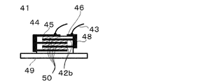
- FIG. 12 shows the internal structure of the electroacoustic transducer 41 according to the third embodiment.
- the connection method of the lead wire 43 that is electrically connected to the second electrode layer 42 b and the second surface electrode layer is not formed on the second surface of the laminated piezoelectric element 44.
- a first surface electrode layer 45 and a third surface electrode 46 are formed on the first surface of the laminated piezoelectric element 44 so as to be separated from the first surface electrode layer 45.
- the second surface electrode layer is not formed on the second surface of the laminated piezoelectric element 44 on the side in contact with the diaphragm.
- the third surface electrode 46 and the second electrode layer 42b are drawn to the side surface opposite to the side surface from which the first surface electrode layer 45 is drawn.
- the third surface electrode 46 and the second electrode layer 42b (the second surface electrode layer is not formed) are connected to the second side electrode 48 formed on the extracted side surface.
- the lead wire 43 electrically connected to the second electrode layer 42b (the second surface electrode layer is not formed) is soldered to the third surface electrode 46 formed on the first surface of the laminated piezoelectric element 44. Is done. Therefore, the second electrode layer 42b is not necessarily connected to the diaphragm 49. Therefore, as the diaphragm 49, a resin can be used in addition to the metal described in the first embodiment. Examples of the resin include PET and urethane.
- the total volume (V) of the effective layer 50 (shaded portion in FIG. 12) of the third embodiment is 6.0 mm 3. And satisfies (Equation 1).
- FIG. 13 shows the appearance of an electroacoustic transducer 51 according to the fourth embodiment.
- a notch 53 is formed in at least one of the apexes of the polygonal laminated piezoelectric element 52.
- the notches 53 can be formed in at least one of the four apexes and a maximum of three.
- the notch 53 serves as a reference point for the laminated piezoelectric element 52, it is possible to reliably perform the operation of forming the side electrode at a specific position or arranging the laminated piezoelectric element 52 at a specific position of the circular diaphragm. . For this reason, variation in sound quality of the electroacoustic transducer is reduced. If it can identify, the shape of the notch 53 will not be ask
- FIG. 14 shows an appearance of an electroacoustic transducer 54 according to the fifth embodiment.
- the circular diaphragm 55 includes four polygonal cutouts 56 on the circumference.
- a straight line 57 that connects a pair of notches 56 that are not adjacent to each other intersects at the center of the circular diaphragm 55.
- the angle at which the straight lines intersect may be 90 ° or any other angle.
- the vertex of the polygon of the laminated piezoelectric element 58 is disposed between two adjacent cutouts 56. Since the notch 56 serves as a reference point, positioning of the laminated piezoelectric element 58 is facilitated.
- the support member 59 includes four protrusions 60 at concentric steps (the two protrusions 60 are hidden behind the steps and are not shown).
- the four protrusions 60 are formed at positions where they fit into the four polygonal cutouts 56. By fitting the notch 56 and the protrusion 60, it becomes easy to fix the electroacoustic transducer 54 to the support member 59.
- the radius of the laminated piezoelectric element must be reduced so that the laminated piezoelectric element does not cover the notch.
- the polygonal laminated piezoelectric elements 58 are arranged such that the apexes of the polygonal piezoelectric elements 58 do not reach the notches 56. Since the laminated piezoelectric element 58 can be arranged without making it small, the sound pressure can be maintained. Note that the radius of the diaphragm 55 provided with the notch 56 is calculated using a virtual circle that is regarded as having no notch. In addition, when a protrusion is formed on the outer peripheral portion of the circular diaphragm, the radius of the diaphragm is calculated using a virtual circle that is regarded as having no protrusion.
- the number of the notches 56 is specified as four, but if there is at least one, it is easy to determine the position of the electroacoustic transducer 54 based on that.
- the shape of the notch 56 is not particularly limited to a polygon as long as it fits into the protrusion.
- the shape of the notch 56 includes a polygon such as a triangle, a quadrangle, a trapezoid, a square, a rectangle, and a pentagon, an arc, a U-shape, and the like.
- the number and shape of the protrusions 60 of the support member 59 are not particularly limited as long as they fit into the notches 56.
- Examples of the shape of the protrusion 60 include a triangle, a quadrangle, a trapezoid, a square, a rectangle, and a polygon such as a pentagon, an arc, a U-shape, and the like. Therefore, all such modifications are included in the scope of the present invention.
- Electroacoustic transducer pieoelectric acoustic component 12
- 34, 44, 52, 58, 62 65
- Diaphragm metal plate 14
- Lead wire 66
- Piezoelectric layer 67
- Electrode layer 16a First electrode layer 16b, 32b, 42b
- Second electrode layer 17, 35, 45, 68 First surface electrode layer 18 , 37, 69 Second surface electrode layer 19
- Second side electrode 22 Region where vibration plate is largely deformed 23 Region where side electrode may be destroyed 24, 40, 50 Effective layer 25
- Margin portion Sound pressure characteristic of electroacoustic transducer provided with square laminated piezoelectric element
Landscapes
- Engineering & Computer Science (AREA)
- Physics & Mathematics (AREA)
- Acoustics & Sound (AREA)
- Signal Processing (AREA)
- Multimedia (AREA)
- Mechanical Engineering (AREA)
- Manufacturing & Machinery (AREA)
- Piezo-Electric Transducers For Audible Bands (AREA)
- Diaphragms For Electromechanical Transducers (AREA)
- Apparatuses For Generation Of Mechanical Vibrations (AREA)
Abstract
Description
圧電体層と電極層とが交互に積層され、極性が異なる少なくとも一対の電極層の間に前記圧電体層が配置された積層圧電素子と、
前記積層圧電素子が配置された振動板とを備え、
前記積層圧電素子は積層方向から見て多角形であり、
前記積層圧電素子が配置される前記振動板の面は円形であり、
前記少なくとも一対の電極層に挟まれる前記圧電体層のうち、積層方向から投影して前記少なくとも一対の電極層が重なる実効層の体積の合計(V)が下記の条件を満たすことを特徴とする電気音響変換装置に関する。
0.2πR2×ts≦V≦2.0πR2×ts
(但し、πは円周率、Rは振動板の半径、tsは振動板の厚み)
前記少なくとも一対の電極層は、極性が異なる第1の電極層と第2の電極層とを含み、 前記第1の電極層は、前記積層圧電素子の一つの側面に形成された第1の側面電極に接続され、
前記第2の電極層は、前記第1の側面電極が形成された側面とは異なる側面に形成された第2の側面電極に接続されることが好ましい。
前記第1の電極層は、前記振動板と接する面とは反対側の前記積層圧電素子の表面に形成された電極層を含むことが好ましい。
図1は、本発明の第1の実施形態に係る電気音響変換装置11の外観を示す。電気音響変換装置11は多角形の積層圧電素子12と、積層圧電素子12が配置される円形の振動板13とを備える。図1に示される電気音響変換装置11は振動板13の片面に積層圧電素子12が配置されているが、振動板13の両面に積層圧電素子12が配置されてもよい。
0.2πR2×ts≦V≦2.0πR2×ts (式1)
(但し、πは円周率、Rは振動板の半径、tsは振動板の厚み)
V=((2αR)/(20.5))2×te (式2)
V=1.6R2×te (式3)
・拘束部:円形の振動板13のエッジ側面
・印加電圧:積層圧電素子12の厚み方向に1VDC/10μm(電界強度一定)
0.3×πR2×ts≦V≦1.3×πR2×ts (式4)
0.4×πR2×ts≦V≦1.0×πR2×ts (式5)
0.2πR2×ts((式1)の左辺)=3.9mm3
2.0πR2×ts((式1)の右辺)=38.7mm3
実効層の体積の合計(V)は7.5mm3であるから、(式1)を満たすことがわかる。
図11は第2の実施形態に係る電気音響変換装置31の内部構造を示す。第2の実施形態は、第2の電極層32bに電気的に接続されるリード線33の接続方法が第1の実施形態と異なる。それ以外は第1の実施形態と同様であるから、異なる点について説明する。
であり、(式1)を満たす。
図12は第3の実施形態に係る電気音響変換装置41の内部構造を示す。第3の実施形態は、第2の電極層42bに電気的に接続されるリード線43の接続方法及び積層圧電素子44の第2の表面に第2の表面電極層が形成されないことが第1の実施形態と異なる。それ以外は第1の実施形態と同様であるから、異なる点について説明する。
であり、(式1)を満たす。
図13は第4の実施形態に係る電気音響変換装置51の外観を示す。本態様では多角形の積層圧電素子52の頂点のうちの少なくとも1つに切り欠き53が形成される。積層圧電素子52が矩形の場合、4つの頂点の少なくとも1つ、最大3つに切り欠き53を形成することができる。
図14は第5の実施形態に係る電気音響変換装置54の外観を示す。円形の振動板55は円周上に4つの多角形の切り欠き56を備える。隣り合わない一対の切り欠き56を結ぶ直線57は円形の振動板55の中心で交わる。直線の交わる角度は90°でも、それ以外の角度でもよい。積層圧電素子58の多角形の頂点は隣り合う2つの切り欠き56の間に配置される。切り欠き56が基準点になるため、積層圧電素子58の位置決めが容易になる。
12、34、44、52、58、62、65 積層圧電素子(圧電板)
13、39、49、55、63 振動板(金属板)
14、33、43、71 リード線
15、66 圧電体層
16、67 電極層
16a 第1の電極層
16b、32b、42b 第2の電極層
17、35、45、68 第1の表面電極層
18、37、69 第2の表面電極層
19 内部電極層
20 第1の側面電極
21、38、48 第2の側面電極
22 振動板の変形が大きな領域
23 側面電極で破壊のおそれのある領域
24、40、50 実効層
25 マージン部
27 正方形の積層圧電素子を備える電気音響変換装置の音圧特性
28 円形の積層圧電素子を備える電気音響変換装置の音圧特性
36、46 第3の表面電極
53、56 切り欠き
57 隣り合わない一対の切り欠きを結ぶ直線
59、64 支持部材(ケース)
60 突起
70 接続電極(スルーホール)
Claims (4)
- 圧電体層と電極層とが交互に積層され、極性が異なる少なくとも一対の電極層の間に前記圧電体層が配置された積層圧電素子と、
前記積層圧電素子が配置された振動板とを備え、
前記積層圧電素子は積層方向から見て多角形であり、
前記積層圧電素子が配置された前記振動板の面は円形であり、
前記少なくとも一対の電極層に挟まれる前記圧電体層のうち、積層方向から投影して前記少なくとも一対の電極層が重なる実効層の体積の合計(V)が下記の条件を満たすことを特徴とする電気音響変換装置。
0.2πR2×ts≦V≦2.0πR2×ts
(但し、πは円周率、Rは振動板の半径、tsは振動板の厚み) - 請求項1に記載の電気音響変換装置において、
前記少なくとも一対の電極層は、極性が異なる第1の電極層と第2の電極層とを含み、
前記第1の電極層は、前記積層圧電素子の一つの側面に形成された第1の側面電極に接続され、
前記第2の電極層は、前記第1の側面電極が形成された側面とは異なる側面に形成された第2の側面電極に接続されることを特徴とする電気音響変換装置。 - 請求項2に記載の電気音響変換装置において、
前記第1の電極層は、前記振動板と接する面とは反対側の前記積層圧電素子の表面に形成された電極層を含むことを特徴とする電気音響変換装置。 - 請求項1~3のいずれかに記載の電気音響変換装置において、前記積層圧電素子は積層方向から見て正方形であることを特徴とする電気音響変換装置。
Priority Applications (3)
| Application Number | Priority Date | Filing Date | Title |
|---|---|---|---|
| CN201580040597.5A CN106576209B (zh) | 2014-10-24 | 2015-08-31 | 电声转换装置 |
| US15/514,793 US10121956B2 (en) | 2014-10-24 | 2015-08-31 | Electroacoustic transducer |
| KR1020177003001A KR101798362B1 (ko) | 2014-10-24 | 2015-08-31 | 전기 음향 변환 장치 |
Applications Claiming Priority (4)
| Application Number | Priority Date | Filing Date | Title |
|---|---|---|---|
| JP2014217703 | 2014-10-24 | ||
| JP2014-217703 | 2014-10-24 | ||
| JP2015-105778 | 2015-05-25 | ||
| JP2015105778A JP5798699B1 (ja) | 2014-10-24 | 2015-05-25 | 電気音響変換装置 |
Publications (1)
| Publication Number | Publication Date |
|---|---|
| WO2016063628A1 true WO2016063628A1 (ja) | 2016-04-28 |
Family
ID=54348656
Family Applications (1)
| Application Number | Title | Priority Date | Filing Date |
|---|---|---|---|
| PCT/JP2015/074559 Ceased WO2016063628A1 (ja) | 2014-10-24 | 2015-08-31 | 電気音響変換装置 |
Country Status (5)
| Country | Link |
|---|---|
| US (1) | US10121956B2 (ja) |
| JP (2) | JP5798699B1 (ja) |
| KR (1) | KR101798362B1 (ja) |
| CN (1) | CN106576209B (ja) |
| WO (1) | WO2016063628A1 (ja) |
Cited By (1)
| Publication number | Priority date | Publication date | Assignee | Title |
|---|---|---|---|---|
| CN109804642A (zh) * | 2016-10-06 | 2019-05-24 | 微软技术许可有限责任公司 | 扬声器布置 |
Families Citing this family (9)
| Publication number | Priority date | Publication date | Assignee | Title |
|---|---|---|---|---|
| GB2551848A (en) * | 2016-07-01 | 2018-01-03 | Zwipe As | Biometric device with low power usage |
| US10312429B2 (en) * | 2016-07-28 | 2019-06-04 | Eyob Llc | Magnetoelectric macro fiber composite fabricated using low temperature transient liquid phase bonding |
| US11296272B2 (en) * | 2017-07-20 | 2022-04-05 | Taiyo Yuden Co., Ltd. | Multilayer piezoelectric element, piezoelectric vibration apparatus, and electronic device |
| JPWO2020158952A1 (ja) * | 2019-01-31 | 2021-12-02 | 太陽誘電株式会社 | 振動センサ |
| JP7151517B2 (ja) * | 2019-01-31 | 2022-10-12 | Tdk株式会社 | 音響装置及び電子機器 |
| CN109985796A (zh) * | 2019-03-25 | 2019-07-09 | 中国船舶重工集团公司第七一五研究所 | 一种多边形阵元压电复合材料换能器制备方法 |
| EP4184946A4 (en) * | 2020-12-31 | 2024-02-21 | Shenzhen Shokz Co., Ltd. | BONE CONDUCTION BASED SOUND CONDUCTION DEVICE |
| JP7706891B2 (ja) * | 2021-01-28 | 2025-07-14 | Tdk株式会社 | 振動デバイス |
| KR102667384B1 (ko) * | 2022-01-18 | 2024-05-21 | 한국전자기술연구원 | 햅틱 액추에이터 |
Citations (3)
| Publication number | Priority date | Publication date | Assignee | Title |
|---|---|---|---|---|
| JP2001238291A (ja) * | 1999-12-16 | 2001-08-31 | Murata Mfg Co Ltd | 圧電音響部品およびその製造方法 |
| WO2013021906A1 (ja) * | 2011-08-08 | 2013-02-14 | 北陸電気工業株式会社 | 圧電発音素子 |
| JP5304252B2 (ja) * | 2007-01-12 | 2013-10-02 | 日本電気株式会社 | 圧電アクチュエータおよび電子機器 |
Family Cites Families (19)
| Publication number | Priority date | Publication date | Assignee | Title |
|---|---|---|---|---|
| JP2745147B2 (ja) * | 1989-03-27 | 1998-04-28 | 三菱マテリアル 株式会社 | 圧電変換素子 |
| JP3241129B2 (ja) * | 1992-11-20 | 2001-12-25 | 太平洋セメント株式会社 | 振動波モータ用の積層型圧電素子及びその製造方法 |
| US6291932B1 (en) * | 1998-02-17 | 2001-09-18 | Canon Kabushiki Kaisha | Stacked piezoelectric element and producing method therefor |
| JPH11355892A (ja) | 1998-06-11 | 1999-12-24 | Murata Mfg Co Ltd | 圧電振動板およびこの圧電振動板を用いた圧電音響部品 |
| US6437484B1 (en) * | 1998-12-24 | 2002-08-20 | Kyocera Corporation | Piezoelectric resonator |
| JP4429417B2 (ja) | 1999-06-30 | 2010-03-10 | 太陽誘電株式会社 | 圧電発音体 |
| US20020130589A1 (en) * | 2001-01-29 | 2002-09-19 | Hiroshi Hamada | Piezoelectric vibrator, piezoelectric vibration apparatus for using the same and manufacturing method therefor |
| US20030020377A1 (en) * | 2001-07-30 | 2003-01-30 | Ngk Insulators, Ltd. | Piezoelectric/electrostrictive element and piezoelectric/electrostrictive device and production method thereof |
| JP3882890B2 (ja) * | 2001-10-19 | 2007-02-21 | 株式会社村田製作所 | 圧電型電気音響変換器 |
| JP3925414B2 (ja) * | 2002-04-26 | 2007-06-06 | 株式会社村田製作所 | 圧電型電気音響変換器 |
| JP4003686B2 (ja) * | 2003-04-10 | 2007-11-07 | 株式会社村田製作所 | 圧電型電気音響変換器 |
| US20060028097A1 (en) * | 2004-06-18 | 2006-02-09 | Norikazu Sashida | Piezoelectric loudspeaker |
| JP2006287314A (ja) * | 2005-03-31 | 2006-10-19 | Taiyo Yuden Co Ltd | 圧電振動板及びそれを利用した電子機器 |
| CA2607918A1 (en) * | 2005-05-18 | 2006-11-23 | Kolo Technologies, Inc. | Micro-electro-mechanical transducers |
| CN201150130Y (zh) * | 2008-02-01 | 2008-11-12 | 瑞声声学科技(常州)有限公司 | 微型压电扬声器 |
| WO2012112540A2 (en) * | 2011-02-15 | 2012-08-23 | Fujifilm Dimatix, Inc. | Piezoelectric transducers using micro-dome arrays |
| CN103918097A (zh) * | 2011-08-09 | 2014-07-09 | 诺力克有限公司 | 具有高的有效机电耦合系数的压电变压器 |
| IL225374A0 (en) * | 2013-03-21 | 2013-07-31 | Noveto Systems Ltd | Array@Matamari |
| US9437802B2 (en) * | 2013-08-21 | 2016-09-06 | Fujifilm Dimatix, Inc. | Multi-layered thin film piezoelectric devices and methods of making the same |
-
2015
- 2015-05-25 JP JP2015105778A patent/JP5798699B1/ja active Active
- 2015-08-21 JP JP2015163964A patent/JP2016086409A/ja active Pending
- 2015-08-31 WO PCT/JP2015/074559 patent/WO2016063628A1/ja not_active Ceased
- 2015-08-31 CN CN201580040597.5A patent/CN106576209B/zh active Active
- 2015-08-31 US US15/514,793 patent/US10121956B2/en active Active
- 2015-08-31 KR KR1020177003001A patent/KR101798362B1/ko active Active
Patent Citations (3)
| Publication number | Priority date | Publication date | Assignee | Title |
|---|---|---|---|---|
| JP2001238291A (ja) * | 1999-12-16 | 2001-08-31 | Murata Mfg Co Ltd | 圧電音響部品およびその製造方法 |
| JP5304252B2 (ja) * | 2007-01-12 | 2013-10-02 | 日本電気株式会社 | 圧電アクチュエータおよび電子機器 |
| WO2013021906A1 (ja) * | 2011-08-08 | 2013-02-14 | 北陸電気工業株式会社 | 圧電発音素子 |
Cited By (2)
| Publication number | Priority date | Publication date | Assignee | Title |
|---|---|---|---|---|
| CN109804642A (zh) * | 2016-10-06 | 2019-05-24 | 微软技术许可有限责任公司 | 扬声器布置 |
| CN109804642B (zh) * | 2016-10-06 | 2021-01-19 | 微软技术许可有限责任公司 | 扬声器布置 |
Also Published As
| Publication number | Publication date |
|---|---|
| US10121956B2 (en) | 2018-11-06 |
| CN106576209B (zh) | 2020-06-05 |
| JP2016086409A (ja) | 2016-05-19 |
| KR101798362B1 (ko) | 2017-11-15 |
| JP5798699B1 (ja) | 2015-10-21 |
| JP2016086405A (ja) | 2016-05-19 |
| KR20170024612A (ko) | 2017-03-07 |
| US20170222118A1 (en) | 2017-08-03 |
| CN106576209A (zh) | 2017-04-19 |
Similar Documents
| Publication | Publication Date | Title |
|---|---|---|
| JP5798699B1 (ja) | 電気音響変換装置 | |
| US7586241B2 (en) | Electroacoustic transducer | |
| JP4069161B2 (ja) | 圧電素子及び超音波アクチュエータ | |
| JP3123435B2 (ja) | 圧電型電気音響変換器 | |
| JP6367693B2 (ja) | 圧電素子、圧電振動装置、音響発生器、音響発生装置および電子機器 | |
| JP2019146020A (ja) | 超音波センサー、超音波装置、及び超音波センサーの製造方法 | |
| US20150125009A1 (en) | Acoustic generator, acoustic generation device, and electronic apparatus | |
| JPWO2014050214A1 (ja) | 音響発生器、音響発生装置及び電子機器 | |
| JP2019535127A (ja) | 圧電アクチュエータ、水中音響トランスデューサ及び水中音響トランスデューサの製造方法 | |
| JPWO2018016630A1 (ja) | 圧電振動発生デバイス及び圧電振動発生デバイスを備えた機器 | |
| JP6434373B2 (ja) | 圧電アクチュエータおよびこれを備えた圧電振動装置、音響発生器、音響発生装置、電子機器 | |
| JP2013157439A (ja) | 圧電素子および圧電アクチュエータ | |
| WO2019131135A1 (ja) | 圧電素子 | |
| JP7354575B2 (ja) | 圧電素子、振動デバイス及び電子機器 | |
| JP7671163B2 (ja) | 音響デバイス | |
| JP7151517B2 (ja) | 音響装置及び電子機器 | |
| JP5871753B2 (ja) | 音響発生器、音響発生装置および電子機器 | |
| US11746000B2 (en) | MEMS device | |
| WO2024237304A1 (ja) | SoTモジュール | |
| WO2026014253A1 (ja) | 音響機器 | |
| JP2022184499A (ja) | 音響デバイス | |
| JP6431086B2 (ja) | 圧電素子、音響発生器、音響発生装置および電子機器 | |
| WO2025134808A1 (ja) | アクチュエータ | |
| JP2024066303A (ja) | 電気音響変換器、音響機器、ウェアラブルデバイス | |
| WO2014103427A1 (ja) | 音響発生器、音響発生装置および電子機器 |
Legal Events
| Date | Code | Title | Description |
|---|---|---|---|
| 121 | Ep: the epo has been informed by wipo that ep was designated in this application |
Ref document number: 15852963 Country of ref document: EP Kind code of ref document: A1 |
|
| ENP | Entry into the national phase |
Ref document number: 20177003001 Country of ref document: KR Kind code of ref document: A |
|
| WWE | Wipo information: entry into national phase |
Ref document number: 15514793 Country of ref document: US |
|
| NENP | Non-entry into the national phase |
Ref country code: DE |
|
| 122 | Ep: pct application non-entry in european phase |
Ref document number: 15852963 Country of ref document: EP Kind code of ref document: A1 |