WO2016060026A1 - Véhicule de travail - Google Patents
Véhicule de travail Download PDFInfo
- Publication number
- WO2016060026A1 WO2016060026A1 PCT/JP2015/078379 JP2015078379W WO2016060026A1 WO 2016060026 A1 WO2016060026 A1 WO 2016060026A1 JP 2015078379 W JP2015078379 W JP 2015078379W WO 2016060026 A1 WO2016060026 A1 WO 2016060026A1
- Authority
- WO
- WIPO (PCT)
- Prior art keywords
- engine
- exhaust
- pipe
- exhaust gas
- bracket
- Prior art date
Links
Images


Classifications
-
- B—PERFORMING OPERATIONS; TRANSPORTING
- B60—VEHICLES IN GENERAL
- B60K—ARRANGEMENT OR MOUNTING OF PROPULSION UNITS OR OF TRANSMISSIONS IN VEHICLES; ARRANGEMENT OR MOUNTING OF PLURAL DIVERSE PRIME-MOVERS IN VEHICLES; AUXILIARY DRIVES FOR VEHICLES; INSTRUMENTATION OR DASHBOARDS FOR VEHICLES; ARRANGEMENTS IN CONNECTION WITH COOLING, AIR INTAKE, GAS EXHAUST OR FUEL SUPPLY OF PROPULSION UNITS IN VEHICLES
- B60K11/00—Arrangement in connection with cooling of propulsion units
- B60K11/06—Arrangement in connection with cooling of propulsion units with air cooling
-
- B—PERFORMING OPERATIONS; TRANSPORTING
- B60—VEHICLES IN GENERAL
- B60K—ARRANGEMENT OR MOUNTING OF PROPULSION UNITS OR OF TRANSMISSIONS IN VEHICLES; ARRANGEMENT OR MOUNTING OF PLURAL DIVERSE PRIME-MOVERS IN VEHICLES; AUXILIARY DRIVES FOR VEHICLES; INSTRUMENTATION OR DASHBOARDS FOR VEHICLES; ARRANGEMENTS IN CONNECTION WITH COOLING, AIR INTAKE, GAS EXHAUST OR FUEL SUPPLY OF PROPULSION UNITS IN VEHICLES
- B60K13/00—Arrangement in connection with combustion air intake or gas exhaust of propulsion units
- B60K13/04—Arrangement in connection with combustion air intake or gas exhaust of propulsion units concerning exhaust
-
- F—MECHANICAL ENGINEERING; LIGHTING; HEATING; WEAPONS; BLASTING
- F01—MACHINES OR ENGINES IN GENERAL; ENGINE PLANTS IN GENERAL; STEAM ENGINES
- F01N—GAS-FLOW SILENCERS OR EXHAUST APPARATUS FOR MACHINES OR ENGINES IN GENERAL; GAS-FLOW SILENCERS OR EXHAUST APPARATUS FOR INTERNAL COMBUSTION ENGINES
- F01N13/00—Exhaust or silencing apparatus characterised by constructional features ; Exhaust or silencing apparatus, or parts thereof, having pertinent characteristics not provided for in, or of interest apart from, groups F01N1/00 - F01N5/00, F01N9/00, F01N11/00
- F01N13/14—Exhaust or silencing apparatus characterised by constructional features ; Exhaust or silencing apparatus, or parts thereof, having pertinent characteristics not provided for in, or of interest apart from, groups F01N1/00 - F01N5/00, F01N9/00, F01N11/00 having thermal insulation
-
- F—MECHANICAL ENGINEERING; LIGHTING; HEATING; WEAPONS; BLASTING
- F01—MACHINES OR ENGINES IN GENERAL; ENGINE PLANTS IN GENERAL; STEAM ENGINES
- F01N—GAS-FLOW SILENCERS OR EXHAUST APPARATUS FOR MACHINES OR ENGINES IN GENERAL; GAS-FLOW SILENCERS OR EXHAUST APPARATUS FOR INTERNAL COMBUSTION ENGINES
- F01N3/00—Exhaust or silencing apparatus having means for purifying, rendering innocuous, or otherwise treating exhaust
- F01N3/08—Exhaust or silencing apparatus having means for purifying, rendering innocuous, or otherwise treating exhaust for rendering innocuous
- F01N3/10—Exhaust or silencing apparatus having means for purifying, rendering innocuous, or otherwise treating exhaust for rendering innocuous by thermal or catalytic conversion of noxious components of exhaust
- F01N3/24—Exhaust or silencing apparatus having means for purifying, rendering innocuous, or otherwise treating exhaust for rendering innocuous by thermal or catalytic conversion of noxious components of exhaust characterised by constructional aspects of converting apparatus
- F01N3/28—Construction of catalytic reactors
-
- F—MECHANICAL ENGINEERING; LIGHTING; HEATING; WEAPONS; BLASTING
- F02—COMBUSTION ENGINES; HOT-GAS OR COMBUSTION-PRODUCT ENGINE PLANTS
- F02B—INTERNAL-COMBUSTION PISTON ENGINES; COMBUSTION ENGINES IN GENERAL
- F02B77/00—Component parts, details or accessories, not otherwise provided for
- F02B77/11—Thermal or acoustic insulation
-
- Y—GENERAL TAGGING OF NEW TECHNOLOGICAL DEVELOPMENTS; GENERAL TAGGING OF CROSS-SECTIONAL TECHNOLOGIES SPANNING OVER SEVERAL SECTIONS OF THE IPC; TECHNICAL SUBJECTS COVERED BY FORMER USPC CROSS-REFERENCE ART COLLECTIONS [XRACs] AND DIGESTS
- Y02—TECHNOLOGIES OR APPLICATIONS FOR MITIGATION OR ADAPTATION AGAINST CLIMATE CHANGE
- Y02A—TECHNOLOGIES FOR ADAPTATION TO CLIMATE CHANGE
- Y02A50/00—TECHNOLOGIES FOR ADAPTATION TO CLIMATE CHANGE in human health protection, e.g. against extreme weather
- Y02A50/20—Air quality improvement or preservation, e.g. vehicle emission control or emission reduction by using catalytic converters
Definitions
- the present invention relates to a work vehicle such as a tractor for agricultural work or a wheel loader for civil engineering work.
- Exhaust gas that purifies air pollutants in exhaust gas in agricultural vehicles and construction civil engineering machinery equipped with the engine in accordance with the recent high-level exhaust gas regulations related to diesel engines (hereinafter simply referred to as engines) It is required to install a purification device.
- a diesel particulate filter hereinafter referred to as DPF
- DPF diesel particulate filter
- Patent Document 1 discloses a structure of a tractor in which an engine is mounted on the front part of a traveling machine body, a front and rear longitudinal DPF is disposed on the left and right sides of an exhaust manifold above the engine, and the engine is covered with a bonnet together with the DPF. Yes.
- the bonnet is formed in a U-shaped cross section downward. For this reason, the left and right corners of the bonnet project outward.
- the DPF is positioned inside the left and right corners, that is, on the left and right corners of the bonnet.
- the space for installing the engine on the work vehicle is not sufficient, and not only the design change on the work vehicle side is forced, but also the problem that the maintainability deteriorates depending on the state of installation of the engine. is there.
- the increase in the size of the engine causes the flow of cooling air in the engine room to deteriorate, which not only reduces the cooling effect, but also due to heat retention in the engine room, not only electronic components but also malfunctions due to heating. There is a risk of inviting.
- the exhaust gas purification device since the high temperature exhaust gas flows inside the exhaust gas purification device, the exhaust gas purification device becomes a high temperature heat source. Therefore, electrical components such as a pressure sensor and a temperature sensor provided in the exhaust gas purification device are affected by radiant heat from the exhaust gas purification device when installed near the exhaust gas purification case. For this reason, there is a risk that an electrical component attached to the exhaust gas purification device may be damaged by heat from the exhaust gas purification device or the engine. In particular, when the failure of the temperature sensor and the pressure sensor occurs, the state of the exhaust gas purification device cannot be confirmed, so that the clogging in the device is not eliminated, resulting in problems such as the occurrence of engine stall. .
- the present invention seeks to provide a work vehicle that has been improved by examining these current conditions.
- a work vehicle of the present invention includes an engine mounted on a front portion of a traveling machine body, a post-processing device that is disposed on the engine and purifies exhaust gas of the engine, and a cooling fan for engine air cooling,
- the cooling fan is disposed on the front side of the engine and the cooling fan
- the engine, and the post-processing device are covered with a bonnet
- the bonnet is below the post-processing device and on one side of the engine
- a perforated plate having a plurality of holes in the shield plate.
- the aftertreatment device is connected to an exhaust manifold provided on one side of the engine, the shielding plate covers the exhaust manifold, and the engine is disposed on one side of the engine below the exhaust manifold. It is good also as what provided the thermal-insulation member connected with, and arrange
- the shielding plate may be a perforated plate configured by arranging a plurality of holes in a matrix, or may be a perforated plate configured by arranging long holes side by side. Further, the shielding plate may be a perforated plate having an opening area on the post-processing device side larger than that on the exhaust manifold lower side.
- an EGR cooler that cools a part of the exhaust gas from the exhaust manifold is provided below the exhaust manifold, and the outside of the EGR cooler is covered with a metal plate disposed below the shielding plate. I do not care.
- an engine mounted on a front portion of a traveling machine body, a post-processing device for purifying exhaust gas of the engine, a radiator for cooling the engine water, a cooling fan for cooling the engine and the radiator air,
- a work vehicle having a fan shroud surrounding the cooling fan and having the post-processing device mounted on the upper side of the engine, wherein the sensor measures an internal environment in the post-processing device above the fan shroud. Since the sensor is placed upstream along the flow direction of the cooling air, the effects of exhaust heat from the engine and the aftertreatment device can be reduced, and sensor failure due to heating can be prevented. it can. Therefore, the engine can be optimally controlled by properly grasping the internal environment of the aftertreatment device.
- the exhaust gas inlet and the exhaust gas outlet of the post-processing device are arranged in the front-rear direction so that the exhaust gas from the engine flows in the post-processing device along the output shaft of the engine, and the post-processing device
- An exhaust gas outlet is provided on the cooling fan side, and a pressure sensor for measuring a pressure difference before and after the purification filter provided in the post-processing device is fixed above the fan shroud, thereby performing post-processing.
- a pressure sensor for measuring the pressure before and after the purification filter provided on the exhaust outlet side of the apparatus along the engine output shaft can be disposed above the fan shroud near the exhaust outlet. Accordingly, since the pressure measurement pipe provided between the sensor and the post-processing apparatus can be shortened, measurement errors due to the pressure sensor can be reduced.
- the work vehicle includes an engine mounted on a front portion of a traveling machine body, and a post-processing device that purifies exhaust gas of the engine, and the post-processing device is mounted on the upper side of the engine via a support bracket.
- a working vehicle that covers the engine and the aftertreatment device with a bonnet, and an external supply pipe for supplying cooling water circulating through the engine to a device outside the engine is provided to the engine via a pipe fixing bracket. It is fixed, and the pipe fixing bracket is erected on the upper part of the engine so as to cover the outer surface of the aftertreatment device, so that it is cooled to an external device such as an air conditioner provided in the traveling vehicle.
- the sensor can be arranged on the opposite side of the post-processing device with the pipe fixing bracket interposed therebetween. The effect of exhaust heat can be reduced, and sensor failure due to heating can be prevented.
- an engine mounted on a front portion of a traveling machine body, a post-processing device disposed on the engine to purify exhaust gas of the engine, and exhaust gas from the post-processing device to the outside
- a work vehicle including an exhaust pipe for exhausting, the exhaust pipe being connected to an exhaust outlet of the aftertreatment device and fixed to the engine, and a downstream side of the first exhaust pipe And an exhaust outlet of the first exhaust pipe, the inner diameter of the second exhaust pipe being larger than the outer diameter of the first exhaust pipe.
- the first and second exhaust pipes are connected and fixed to the engine and the traveling machine body which are different vibration systems by inserting and communicating with the exhaust inlet of the second exhaust pipe. Because of damage to the exhaust pipe It can be prevented.
- outside air can be introduced into the second exhaust pipe together with the exhaust gas from the first exhaust pipe.
- the exhaust gas to be discharged can be cooled.
- the exhaust gas outlet and the exhaust gas inlet of the aftertreatment device are respectively arranged in the front and rear so that the exhaust gas from the engine flows in the aftertreatment device along the output shaft of the engine,
- the exhaust inlet of the first exhaust pipe is connected to the exhaust gas outlet disposed on the front side of the aftertreatment device so that the first exhaust pipe is arranged in parallel with the aftertreatment device above the engine and the rear
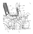
- a steering seat is provided above the traveling body and behind the engine, the exhaust pipe configured in a U shape is fixed in front of the steering seat, and a drainage pipe is disposed below the exhaust pipe.
- a bonnet that covers an engine room provided at a front portion of the traveling machine body, an engine that is a driving source, a cooling fan for cooling the engine, and cooling air that is induced by the cooling fan are allowed to pass through.
- a work vehicle comprising a plurality of heat exchangers for exchanging heat with the cooling medium and covering the upper surface in front of the traveling machine body with a bottom plate, wherein the bonnet and the bottom plate are each opened at a position in front of the cooling fan.
- the cooling fan is configured to take in the cooling air from the openings of the bonnet and the bottom plate by driving the cooling fan.
- the opening area can be expanded more than the air flow rate that allows the air to pass through.
- the flow velocity of the cooling air passing through the cooling fan can be suppressed, and the cooling air in the engine room can be optimally controlled. Further, by providing a net-like opening on the bottom plate, it is possible to prevent dust from entering the engine room and to allow the dust to fall by its own weight after the engine is stopped.
- the left and right front frames and the left and right rear frames are connected to each other in the front-rear direction, and the front ends of the left and right front frames are constructed with a rectangular metal casting connection member to form the traveling body, and the connection
- the connecting member of the traveling machine body is arranged below the opening of the bottom plate, so that when outside air flows into the engine room through the opening, the connection Intrusion of dust and mud can be prevented by the member.
- an engine support structure can be strengthened by fixing the front frame which supports an engine with the connection member used as a metal casting.
- the heat shielding property to the engine can be improved and at the same time, the heat retention on the side of the engine can be prevented. It is possible to optimize the thermal efficiency in the engine room inside the bonnet, thereby preventing abnormal operation of the engine and improving the driving efficiency.
- the influence on the starter due to heat radiation from the exhaust manifold that is at a high temperature is reduced, and failure of the starter that is an electrical device is prevented. Can be prevented.
- the holes of the perforated plate constituting the shielding plate in a matrix shape, not only the opening area of the heat shielding plate can be easily adjusted, but also the opening region can be set flexibly. Also, by making the hole in the perforated plate that constitutes the shielding plate into a long hole, it is easy to equalize the resistance at the opening to the fluid, turbulent flow inside the shielding plate can be suppressed, and stagnation of exhaust heat from the engine etc. Can be reduced.
- the shielding plate by increasing the opening area on the side of the post-processing device as compared with the lower side of the exhaust manifold, the exhaust heat that has risen is more efficiently guided to the post-processing device, and at the same time, the post-processing device By making it easy to exhaust part of the engine cooling air in the opening region on the side, heat retention between the shielding plate and the engine can also be suppressed.
- the cooling air from the front of the engine is guided to the EGR cooler while being heated on the side of the EGR cooler.
- the cooling air can be raised towards the upper aftertreatment device. Therefore, in the engine room, exhaust heat from the engine can be effectively utilized by the post-processing device, while heat retention around the engine can be suppressed.
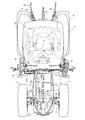
- the traveling machine body 2 of the tractor 1 in the embodiment is supported by a pair of left and right rear wheels 4 as well as a pair of left and right front wheels 3 as a traveling unit.
- the tractor 1 is configured to travel forward and backward by driving the rear wheels 4 and the front wheels 3 with a common rail type diesel engine 5 (hereinafter simply referred to as an engine) as a power source mounted on the front portion of the traveling machine body 2.
- a common rail type diesel engine 5 hereinafter simply referred to as an engine
- the engine 5 is covered with a bonnet 6.
- a cabin 7 is installed on the upper surface of the traveling machine body 2.
- a steering seat 8 and a steering handle (round handle) that moves the steering direction of the front wheel 3 to the left and right by steering. 9 are arranged inside the cabin 7.
- a step 10 on which the operator gets on and off is provided at the outer lower portion of the cabin 7.
- a fuel tank 11 that supplies fuel to the engine 5 is provided below the bottom of the cabin 7.
- the traveling machine body 2 includes an engine frame (front frame) 14 having a front bumper (frame connecting member) 12 and a front axle case 13, and left and right machine body frames (rear frame) 15 detachably fixed to the rear part of the engine frame 14. It is comprised by.
- a front axle 16 is rotatably protruded outward from the left and right ends of the front axle case 13.
- the front wheels 3 are attached to the left and right ends of the front axle case 13 via the front axle 16.
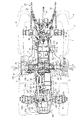
- a transmission case 17 is connected to the rear part of the body frame 15 for appropriately changing the rotational power from the engine 5 and transmitting it to the front and rear four wheels 3, 3, 4, 4.
- a tank frame 18 having a rectangular frame plate shape in a bottom view projecting outward in the left and right directions is bolted to the lower surface sides of the left and right body frames 15 and the mission case 17.
- the fuel tank 11 of the embodiment is divided into left and right two parts.
- the left and right fuel tanks 11 are distributed and mounted on the upper surface side of the left and right projecting portions of the tank frame 18.
- the left and right rear axle cases 19 are mounted on the left and right outer surfaces of the mission case 17 so as to protrude outward.
- Left and right rear axle cases 20 are rotatably inserted in the left and right rear axle cases 19.
- the rear wheel 4 is attached to the mission case 17 via the rear axle 20.
- Upper portions of the left and right rear wheels 4 are covered with left and right rear fenders 21.
- a hydraulic lifting mechanism 22 that lifts and lowers a work machine such as a rotary tiller is detachably attached to the rear upper surface of the mission case 17.
- a working machine such as a rotary tiller is connected to the rear portion of the transmission case 17 via a three-point link mechanism including a pair of left and right lower links 23 and a top link 24.
- a PTO shaft 25 for transmitting a PTO driving force to a working machine such as a rotary tiller is provided to project rearward.
- a flywheel 61 is attached to an engine output shaft 53 that protrudes rearward from the rear side of the engine 5.
- a main shaft 27 projecting rearward from the flywheel 61 and a main transmission input shaft 28 projecting forward from the front side of the transmission case 17 are connected via a power transmission shaft 29 having universal shaft joints at both ends.
- a hydraulic continuously variable transmission, a forward / reverse switching mechanism, a traveling auxiliary transmission gear mechanism, and a differential gear mechanism for rear wheels are arranged in the transmission case 17, a hydraulic continuously variable transmission, a forward / reverse switching mechanism, a traveling auxiliary transmission gear mechanism, and a differential gear mechanism for rear wheels are arranged.
- the rotational power of the engine 5 is transmitted to the main transmission input shaft 28 of the transmission case 17 via the main driving shaft 27 and the power transmission shaft 29, and is appropriately shifted by the hydraulic continuously variable transmission and the traveling auxiliary transmission gear mechanism. Then, the transmission power is transmitted to the left and right rear wheels 4 through the rear wheel differential gear mechanism.
- the front wheel output shaft 30 projecting forward from the lower front portion of the transmission case 17 projects rearward from the front axle case 13 containing a front wheel differential gear mechanism (not shown) via a front wheel drive shaft 31.
- a front wheel transmission shaft (not shown) is connected. Transmission power by the hydraulic continuously variable transmission and the traveling auxiliary transmission gear mechanism in the transmission case 17 is transmitted from the front wheel output shaft 30, the front wheel drive shaft 31, and the front wheel transmission shaft to the front wheel differential gear mechanism in the front axle case 13. Is transmitted to the left and right front wheels 3 via.
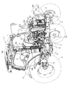
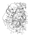
- the turbocharger 81 of the engine 5 includes a compressor case 83 with a built-in blower wheel.
- the intake side of the compressor case 83 is connected to the intake / exhaust side of the air cleaner 221 via an air supply pipe 222.
- the intake / discharge side 83 is connected to the upstream relay pipe 223.
- the turbocharger 81 includes a turbine case 82 with a built-in turbine wheel.
- the turbocharger 81 connects the exhaust intake side of the turbine case 82 to the exhaust gas outlet of the exhaust manifold 57, while the intake discharge side of the turbine case 82 is connected to the rear side. It connects with the exhaust-gas inlet_port
- the engine 5 is connected to the EGR cooler 80 and the EGR device 75 that are arranged on both sides by a recirculation exhaust gas pipe 78 that bypasses the rear surface of the engine 5 (the flywheel 61 side) as a reflux line.
- the EGR device 75 is connected to the downstream relay pipe 225 extending forward (on the cooling fan 59 side) on the right side of the engine 5.
- the upstream relay pipe 223 and the downstream relay pipe 225 are respectively arranged on both sides of the engine 5, and the front upper side of the engine 5 is connected to the intercooler 224 installed on the frame frame 226 in front of the engine 5. It is extended toward.
- the air cleaner 221 is arranged on the upper front side of the frame frame 226, and an air supply pipe 222 connected to the air cleaner 221 extends over the frame frame 226 and extends behind the left side of the engine 5.
- fresh air (external air) sucked into the air cleaner 221 is removed by the air cleaner 221 and purified, and then sucked into the compressor case 83 of the turbocharger 81 through the air supply pipe 222.
- the pressurized fresh air compressed in the compressor case 83 of the turbocharger 81 is supplied to the EGR main body case of the EGR device 75 via the relay pipes 223 and 225 and the intercooler 224.
- part of the exhaust gas (EGR gas) from the exhaust manifold 57 is cooled by the EGR cooler 80 and then supplied to the EGR main body case of the EGR device 75 via the recirculation exhaust gas pipe 78.
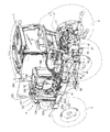
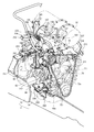
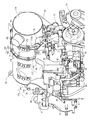
- the exhaust gas purification device 52 is provided with an exhaust gas inlet pipe 161 on the outer peripheral surface of the case on one end side (rear side) in the longitudinal direction, and the exhaust gas inlet pipe 161 is connected to the exhaust gas of the turbine case 82 in the turbocharger 81.
- the exhaust side communicates with the exhaust side through an exhaust communication pipe 84.
- the exhaust gas purifying device 52 is provided with an exhaust gas outlet pipe 162 on the outer peripheral surface of the case on the other end side (front side) in the longitudinal direction, and the exhaust gas outlet pipe 162 is connected to the exhaust pipe 227.
- the exhaust gas inlet pipe 161 is opened toward the lower left side, while the exhaust gas outlet pipe 162 is opened upward on the right side.
- the exhaust pipe 227 is disposed so as to straddle the upper side of the engine 5 from the front left side of the diesel engine 5 to the rear right side.
- the exhaust pipe 227 is installed at a position between the exhaust gas purification device 52 and the downstream relay pipe 225 so as to be substantially parallel to the exhaust gas purification device 52 and the downstream relay pipe 225.
- the exhaust gas purifying device 52 and the exhaust pipe 227 are arranged side by side so as to be parallel to the output shaft of the engine 5. That is, the exhaust gas purification device 52 and the exhaust pipe 227 are arranged side by side so that the exhaust gas purification device 52 covers the left side of the upper surface of the engine 5 while the exhaust pipe 227 covers the right side of the upper surface of the diesel engine 5. Further, on the right side of the exhaust pipe 227, a downstream relay pipe 225 that connects the intercooler 224 and the intake communication pipe 76 is installed, and the thermal influence on the downstream relay pipe 225 by the exhaust gas purifying device 52 that becomes high temperature. Is preventing.
- the exhaust pipe (first exhaust pipe) 227 connected to the exhaust side of the exhaust gas purification device 52 is inserted into the exhaust gas intake port of the tail pipe (second exhaust pipe) 229 on the right rear side of the diesel engine 5.
- the tail pipe 229 has a J-shape that extends from the lower side toward the upper side toward the exhaust gas discharge side and is bent toward the diesel engine 5 on the lower side of the cabin 7 on the front right side of the cabin 7. ing.
- the exhaust pipe 227 includes an umbrella-shaped upper surface cover body 228 on the outer peripheral surface above the portion inserted into the tail pipe 229.
- the upper surface cover body 228 is fixed radially to the outer peripheral surface of the exhaust pipe 227 so as to cover the exhaust gas intake port of the tail pipe 229 and prevent intrusion of dust and rainwater into the tail pipe 229.
- the tail pipe 229 is formed such that the lower bent portion straddles the upper part of the body frame 15 from the inside to the outside. Further, the tail pipe 229 is provided with an exhaust gas intake port provided inside the body frame 15 at an upper side, and the exhaust gas discharge port of the exhaust pipe 227 is inserted into the exhaust gas intake port. That is, the connection portion between the tail pipe 229 and the exhaust pipe 227 has a double pipe structure, and exhaust gas flows into the tail pipe 229 from the exhaust pipe 227 and at the same time, a gap between the exhaust pipe 227 and the tail pipe 229. The exhaust gas flowing in the tail pipe 229 is cooled by allowing the outside air to flow in. Furthermore, the tail pipe 229 is configured to be covered with a heat shield plate 230. An engine cover 232 formed of a perforated plate is disposed on the lower left and right sides of the bonnet 6 to cover the left and right sides of the engine room.
- the transmission case 17 includes a front transmission case 112 having a main transmission input shaft 28 and the like, a rear transmission case 113 having a rear axle case 19 and the like, and a front side of the rear transmission case 113 connected to the rear side of the front transmission case 112.
- An intermediate case 114 is provided.
- the rear ends of the left and right machine body frames 15 are connected to the left and right side surfaces of the intermediate case 114 via the left and right upper and lower machine body connecting shafts 115 and 116. That is, the rear end portions of the left and right airframe frames 15 are connected to the left and right side surfaces of the intermediate case 114 by the two upper airframe connecting shaft bodies 115 and the two lower airframe connecting shaft bodies 116.
- the mission case 17 is integrally connected to form the rear part of the traveling machine body 2. Further, the front transmission case 112 or the power transmission shaft 29 is disposed between the left and right body frames 15 to configure the traveling machine body 2 so as to protect the front transmission case 112 and the like.
- left and right front support bases 96 that support the front side of the cabin 7 and left and right rear support bases 97 that support the rear part of the cabin 7 are provided.
- a front support 96 is bolted to the front end of the left and right machine frame 15 and the front bottom of the cabin 7 is supported on the upper surface of the front support 96 via a vibration isolating rubber member 98. is doing.
- a rear support 97 is fastened to the middle of the left and right widths of the upper surface of the left and right rear axle cases 19 extending horizontally in the left-right direction, and the cabin 7 is connected to the upper surface of the rear support 97 via a vibration isolating rubber body 99.
- Anti-vibration support is provided at the rear bottom. Accordingly, the traveling machine body 2 supports the cabin 7 in a vibration-proof manner via the plurality of vibration-proof rubber bodies 98 and 99.
- a rear support 97 is disposed on the upper surface side of the rear axle case 19 and an anti-sway bracket 101 is disposed on the lower surface side of the rear axle case 19 so that the end face of the cross section sandwiches the rear axle case 19 having a substantially rectangular tube shape.
- the rear support 97 and the steady bracket 101 are fastened with bolts 102.
- Both ends of a steady-state rod body 103 with turnbuckles that can be expanded and contracted are connected to an intermediate portion of the lower link 23 that extends in the front-rear direction and the steady-rest bracket 101 to prevent left-right vibration of the lower link 23. is doing.
- the bonnet 6 forms a front grill 231 on the front lower side and covers the front of the engine room.
- An engine cover 232 formed of a perforated plate is disposed on the lower left and right sides of the bonnet 6 to cover the left and right sides of the engine room. That is, the hood 6 and the engine cover 232 cover the front, upper, and left and right sides of the diesel engine 5.
- the bonnet 6 includes a front grille 231 at the center of the front surface, and the ceiling portion on the upper side of the bonnet 6 has a shape inclined obliquely upward from the front to the rear.
- the front grill 231 includes a pair of left and right dustproof nets 231b fixed by a central frame 231a.
- the bonnet 6 has a wider space at the lower rear side of the ceiling, and a large space for accommodating the exhaust gas purification device 52 can be formed in the engine room inside the bonnet 6.
- the bonnet 6 has an opening hole 268 in front of each of the left and right side surfaces, and takes in cooling air from both the left and right sides of the bonnet 6 through a pair of left and right opening holes 268.
- the bonnet 6 is also provided with a pair of left and right net-like opening holes 270 in front of the ceiling, and the cooling air is taken in from the upper front side of the bonnet 6 through the pair of left and right opening holes 270.
- the opening holes 268 and 270 are covered with a net-like dustproof net.
- the paired left and right engine frames (front frame) 14 have their front end side inner surfaces connected to the left and right outer surfaces of the frame connecting member 12.
- the frame connecting member 12 is made of a rectangular metal casting, and the diesel engine 5 is supported on the engine frame 14 installed by the frame connecting member 12.
- a frame bottom plate 233 is installed on the upper edges of the left and right engine frames 14 and the upper surface of the front bumper 12 so as to cover the upper front side of the engine frame 14.
- a radiator 235 having a fan shroud 234 attached to the back side is erected on the frame bottom plate 233 so as to be positioned on the front side of the engine 5.
- the fan shroud 234 surrounds the outer peripheral side of the cooling fan 59 and allows the radiator 235 and the cooling fan 59 to communicate with each other.
- the lower surface of the frame bottom plate 233 is connected to the side surfaces of the left and right engine frames 14 via connecting brackets 233a and 233b arranged on the front and rear sides. Further, the frame bottom plate 233 is constituted by a front bottom plate 233x and a rear bottom plate 233y which are divided into front and rear parts. The left and right edge sides of the lower surface of the front bottom plate 233x are connected to the front of the other end of the connection bracket 233a that connects one end to the side of the pair of left and right engine frames 14, and the front side of the front bottom plate 233x is fastened to the frame connecting member 12. Has been.
- the rear bottom plate 233y connects the left and right edge sides of the front lower surface with the other end rear of the pair of left and right connection brackets 233a, and connects the left and right edge sides of the front lower surface to the other ends of the pair of left and right connection brackets 233b.
- the frame bottom plate 233 is provided with an opening hole 233z in the left and right central region.
- the opening hole 233z is provided in the front bottom plate 233x of the frame bottom plate 233 and is covered with a net-like dustproof net. That is, each of the bonnet 6 and the frame bottom plate 233 has openings 231b, 233a, 268, 270 at positions ahead of the cooling fan 59 of the engine 5, and the bonnet 6 and the frame bottom plate are driven by the cooling fan 59. Cooling air is taken into the engine room in the hood 5 from the openings 231 b, 233 a, 268, and 270 of the respective 233.
- the opening area can be made larger than the air flow rate through which the cooling fan 59 passes. Thereby, the flow velocity of the cooling air passing through the cooling fan 59 can be suppressed, and the cooling air in the engine room can be optimally controlled. Further, by providing the frame bottom plate 233 with a net-like opening, it is possible to prevent the intrusion of dust into the engine room, and the dust can be dropped by its own weight after the engine 5 is stopped.
- the opening 233z of the frame bottom plate 233 is disposed at a position above the frame connecting member 12. Since the frame connecting member 12 of the traveling machine body 2 is disposed below the opening 233z of the frame bottom plate 233, when the outside air flows into the engine room through the opening 233z, the frame connecting member 12 prevents dust and mud from entering. Can do. Moreover, the support structure of the engine 5 can be strengthened by fixing the engine frame 14 that supports the engine 5 with the frame connecting member 12 that is a metal casting.
- a rectangular frame-shaped frame 226 is erected on the rear bottom plate 233y of the frame bottom plate 233.
- a frame frame 226, a radiator 235, and a fan shroud 234 are arranged in order from the front above the frame connecting member 12 that bridges the left and right engine frames 14.
- the frame frame 226 is formed so that the rear surface is covered with the radiator 235, and the front surface and the left and right side surfaces thereof are covered with a mesh plate.
- the above-described intercooler 224, an oil cooler, a fuel cooler, and the like are installed.
- An air cleaner 221 is disposed above the front surface of the frame frame 226.
- the cooling air sucked from the front grille 231 flows toward the frame frame 226 behind the front grille 231, thereby cooling the air cleaner 221 and cooling the intercooler, oil cooler, and fuel cooler in the frame frame 226. To do.
- the cooling air from the front reaches the radiator 235 provided on the rear surface of the frame frame 226, thereby enhancing the cooling effect on the cooling water supplied to the diesel engine 5.
- the radiator 235 communicates with the cooling water intake port of the thermostat case 70 through the cooling water supply pipe 201 at the upper cooling water discharge port, and with the cooling water intake pipe 202 through the cooling water return pipe 202.
- the cooling water discharge port of the pump 71 is communicated.
- the cooling water in the radiator 235 is supplied to the cooling water pump 71 via the cooling water supply pipe 201 and the thermostat case 70. Then, when the cooling water pump 71 is driven, cooling water is supplied to a water cooling jacket (not shown) formed in the cylinder block 54 and the cylinder head 55 to cool the engine 5. Cooling water that has contributed to cooling of the engine 5 is returned to the radiator 235 via the cooling water return pipe 202.
- thermostat 70 and the cooling water pump 71 are also connected to the hot water pipes 203 and 204, respectively, and circulate cooling water (hot water) contributing to cooling of the engine 5 to the air conditioner 364 of the cabin 7.
- hot water circulates in the air conditioner 364 of the cabin 7, whereby hot air is supplied from the air conditioner 364 into the cabin 7, and the temperature in the cabin 7 can be adjusted to a temperature desired by the operator. .
- the front end sides of the left and right fuselage frames 15 are connected to the rear end sides of the left and right engine frames 14 via spacers 297, and the left and right fuselage frames 15 are arranged so as to sandwich the left and right engine frames 14. Yes.
- the pair of left and right body frames 15 are connected to the front lower side of the floor plate 40 by support beam frames 236.
- the connection surface (outer surface) of the support beam frame 236 with the body frame 15 is the same surface as the connection surface (outer surface) of the spacer 297 with the body frame 15.
- the support beam frame 236 is bolted to the left and right airframe frames 15 to mount the left and right airframe frames 15, and the engine support frame 237 is mounted on the upper surface thereof.
- the engine support frame 237 has a shape that surrounds the flywheel 61 of the diesel engine 5 together with the support beam frame 236 by fastening the lower end surface of the engine support frame 237 with the upper surface of the support beam frame 236.
- the diesel engine 5 includes an engine support bracket 298 provided at a middle portion of the pair of left and right engine frames 14 with an engine leg mounting portion 74 provided on the lower side of the left and right side surfaces thereof via an engine leg 238 having a vibration isolation rubber 239. It is connected.
- an engine leg mounting portion 60 a provided on the rear flywheel housing 60 is connected to the upper surface of the engine support frame 237 via an engine leg (engine mount) 240 having a vibration isolation rubber 241. .
- the engine leg 238 is bolted to the upper part of the engine support bracket 298 connected to the outside of the middle part of the pair of left and right engine frames 14 with the anti-vibration rubber 239 on the lower side.
- the diesel engine 5 is sandwiched between the engine frames 14 by a pair of left and right engine legs 238 to support the front side of the diesel engine 5.
- the rear surface of the diesel engine 5 is connected to the front end sides of the pair of left and right body frames 15 via the support beam frame 236, the engine support frame 237, and the engine legs 240, and the diesel engine 5 is rearward at the front end of the body frame 15 The side is supported.
- the diesel engine 5 is supported on the traveling machine body 2 by the left and right front vibration isolation rubber 239 and the left and right rear vibration isolation rubber 241.
- a pair of left and right support columns 242 and 243 are erected on the upper surface of the engine support frame 237 so as to sandwich the engine leg 240 from the left and right.
- a bonnet shield plate (shield plate) 244 covering the rear of the bonnet 6 is connected to the pair of left and right support frames 242 and 243 so that the lower edge thereof is separated from the upper surface of the engine leg 240.
- the beam frame 248 is installed over the fan shroud 234 and the bonnet shield plate 244, respectively. Since the fan shroud 234 and the bonnet shield plate 244 that are stably supported by the traveling machine body 2 are installed by being connected by a pair of beam frames 248, these members are integrated to form a robust engine room frame body as a whole. it can.
- the exhaust gas purifying device 52 mounted on the upper part of the engine 5 is positioned behind the bonnet 6, and a heat shield plate 250 is disposed between the bonnet 6 and the exhaust gas purifying device 52.
- a heat shield plate 250 is disposed between the bonnet 6 and the exhaust gas purifying device 52.
- a hood shield plate 244 that is disposed on the back side of the bonnet 6 and covers at least the exhaust gas purification device 52 from the back side is provided. Since the heat in the engine room under the hood 6 is shielded by the hood shield plate 244 together with the heat shield plate 250, the cabin 7 can be prevented from being heated by exhaust heat from the engine room. Further, by providing a gap between the bonnet shield plate 244 and the heat shield plate 250, it is difficult to trap hot air in the engine room below the bonnet 6, and heat damage to the exhaust gas purifying device 52 itself, the bonnet 6 and the like is prevented. Generation can be suppressed.
- extendable gas springs (bonnet dampers) 256 and 256 are disposed on the left and right sides of the heat shield plate 250 below the bonnet 6.
- One end (rear end) of each of the left and right gas springs 256, 256 is pivotally attached to the engine room frame body, and the other end (front end) of each of the gas springs 256, 256 is pivotally attached to the upper inner surface of the bonnet 6. is doing. Further, the bonnet 6 is held in the open position by the thrust action of the gas spring 256.
- the bonnet 6 can be held open by the gas spring 256, so that the diesel engine 5 Maintenance work can be performed.
- the bonnet 6 of the tractor 1 is formed in a U-shaped cross section downward. Then, the left and right corners of the bonnet 6 are chamfered so as to be inclined obliquely downward to the left and right outside in a front view, so that the front view of the operator seated on the control seat 8, particularly the left and right sides of the bonnet 6, Good visibility.
- the exhaust gas purification device (DPF) 52 and the exhaust communication pipe 84 are opposed to the left inner wall surface of the bonnet 6, while the intake communication pipe 76 is opposed to the right inner wall surface of the bonnet 6. Further, the exhaust communication pipe 84 is disposed at a position facing the left engine cover 232, while the intake communication pipe 76 is disposed at a position facing the right engine cover 232.
- the intake communication pipe 76 having a hollow portion that supplies fresh air to the intake manifold 56 is inclined upward toward the cylinder head 55, and the upper side from the intake manifold 56. It is extended to. That is, in the intake communication pipe 76, the fresh air intake port on the upper end side is offset toward the output shaft 53 (engine 5 center position) of the engine 5 with respect to the fresh air discharge port on the lower end side.
- the intake communication pipe 76 is arranged along the shape narrowed upward in the bonnet 6, and the intake throttle member 77 is disposed between the upper part of the engine 5 and the inner surface of the bonnet 6 than the intake communication pipe 76. Can be placed closer to the center position.
- downstream relay pipe 225 that allows the fresh air discharge side of the intercooler 224 and the intake throttle member 77 to communicate with each other can be designed to be short, and can be compactly accommodated in the hood 6 that has a narrower left and right width.
- an exhaust communication pipe 84 having a hollow portion for supplying exhaust gas from the exhaust manifold 57 to the exhaust gas purification device 52 is inclined upward toward the cylinder head 55 side.
- the exhaust gas purification device 52 is supported by being connected to the exhaust gas inlet pipe 161 of the exhaust gas purification device 52. That is, the exhaust communication pipe 84 is connected to the lower end side connection support portion 84a connected to the lower end side exhaust manifold 57, and the upper end side exhaust gas discharge port is connected to the output shaft 53 (engine 5 center position) of the engine 5. It is offset closer. Further, the exhaust gas purifying device 52 inclines the exhaust gas inlet pipe 161 toward the lower side (the inlet flange body 161a side) toward the outside of the engine 5 (the inner wall side of the bonnet 6).
- the exhaust gas purification device 52 and the exhaust communication pipe 84 are arranged along a shape narrowed upward in the bonnet 6, and the exhaust gas purification device 52 is disposed between the upper portion of the engine 5 and the inner surface of the bonnet 6. It can be supported near the center position. Therefore, the exhaust gas purifying device 52 can be accommodated in a compact manner in the bonnet 6 whose lateral width becomes narrower upward.
- the exhaust gas purifying device 52 which is a heavy object, can be supported close to the center of gravity of the engine 5, and an increase in vibration, noise, etc. of the engine 5 due to the exhaust gas purifying device 52 being mounted can be suppressed. Further, the influence on the shape of the hood 6 due to the exhaust gas purification device 52 being assembled to the engine 5 can be reduced, and the shape of the hood 6 need not be complicated.
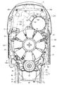
- a flywheel housing 60 that covers a flywheel 61 disposed on an end surface that intersects the core line of the engine output shaft 53 is configured to have a width W1 narrower than a height H1.
- the engine 5 can be mounted without causing the flywheel housing 60 to interfere with the traveling machine body 2 having a narrow left and right width.
- the width between the left and right machine engine frames 15 is wider than the width between the left and right engine frames 14.
- the flywheel housing 60 is disposed rearward, and the main transmission input shaft 28 of the transmission case 17 connected to the body frame 15 and the flywheel 61 are connected. Accordingly, the flywheel housing 60 having the widest left and right width in the engine 5 can be sufficiently disposed between the body frames 15 and the flywheel housing 60 can be prevented from colliding with the traveling body 2 having a different vibration system. Damage can be prevented.
- the flywheel housing 60 has an outer shape in which a left and right sides of a circle are cut out and a pedestal engine leg mounting portion 60a is protruded on the upper portion, and the upper engine leg mounting portion 60a is interposed via a rear engine leg body 240. And connected to the traveling machine body 2.
- the flywheel housing 60 can be mounted on the traveling machine body 2 having a narrow width, and a pedestal-shaped engine leg mounting portion 60 a that can be connected to the traveling machine body 2 is configured. Therefore, the rigidity by the support structure of the engine 5 can be compensated by connecting to the traveling machine body 2 by the flywheel housing 60 having high rigidity.
- a portal-type engine support frame 237 is installed above the support beam frame 236 that bridges the pair of left and right body frames 15, and the flywheel housing 60 and the engine support frame 237 are arranged side by side. . Then, the rear surface of the engine leg 238 is connected to the upper surface of the engine support frame 237 via the vibration isolating rubber 239, while the upper surface of the engine leg mounting portion 60 a on the flywheel housing 60 in front of the engine leg 238 is connected.
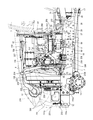
- a porous shielding plate 205 that covers the left side surface of the engine 5 is disposed below the exhaust gas purification device (DPF) 52. Since the shielding plate 205 is configured to cover the exhaust manifold 57, the turbocharger 81, and the exhaust communication pipe 84, the high heat source component in the engine 5 is covered with the shielding plate 205. Therefore, the exhaust gas supplied to the DPF 52 can be maintained at a high temperature, and a decrease in the regeneration capability of the DPF 52 can be prevented. Further, the shielding plate 205 is made porous, and is disposed so as to face the porous left engine cover 232, so that a part of the air heated by the engine 5 can be passed through the shielding plate 205 and the engine cover 232. Heat can be exhausted to the outside, and heat retention on the left side of the engine 5 that becomes relatively high can be prevented.
- DPF exhaust gas purification device
- the shield plate 205 is bolted to the exhaust gas intake port side of the exhaust communication pipe 84 (on the connection portion side with the turbine case 82 of the turbocharger 81), and is connected to the second outlet side via the shield plate fixing bracket 207. It is connected to the rear part connecting portion 182 d of the bracket 182 and supported by the engine 5.
- the shielding plate fixing bracket 207 is also connected to an upstream relay pipe 223 that communicates the fresh air intake port of the intercooler 224 and the compressor case 83 of the turbocharger 81, and the upstream relay pipe 223 is also connected to the engine 5. Is supported by the second bracket 182 on the outlet side.
- a heat shield member 206 connected to one side of the engine 5 is provided below the exhaust manifold 57, and an engine starter 69 is arranged below the heat shield member 206.
- the heat shield member 206 connected to the left side surface of the cylinder block 54 is erected toward the engine cover 232 at a position between the engine starter 69 and the EGR cooler 80. Accordingly, by covering the starter 69, which is an electrical device, with the heat shield member 206, the thermal influence on the starter 69 due to heat radiation from the exhaust manifold 57 or the like that becomes high is reduced, and the starter, which is an electrical device, is started. The failure of the starter 69 can be prevented.
- an oil filter 63 for filtering lubricating oil from an oil pan 62 is connected to a cylinder block via an oil filter supporting member (supporting bracket) 88 having a hollow portion for allowing the lubricating oil to pass therethrough.
- 54 is disposed below the right side surface.
- An oil pump (not shown) is disposed on the front side (cooling fan 59 side) in a portion near the right side surface in the cylinder block 54, and an oil passage (not shown) is directed rearward from the oil pump (not shown). Is provided.
- One side surface (left side surface) of the oil filter support member 88 is connected to a connection port (oil filter mounting position) with the oil passage provided in the cylinder block 54, and the other side surface (right side surface) of the oil filter support member 88.
- the oil filter 63 is attached on the upper side.
- the oil filter 63 has an oil filter support member 88 interposed when the oil filter 63 is attached to the cylinder block 54. Therefore, the oil filter 63 is disposed above the original mounting position in the cylinder block 54, and interferes with the traveling machine body 2 even when the engine 5 is mounted on the traveling machine body 2 having a narrow left and right width. There is nothing. That is, as shown in FIGS. 15 and 16, the oil filter 63 is disposed above the engine frame 14 by the oil filter support member 88. Therefore, the oil filter 63 can be easily accessed, and the oil filter 63 can be easily replaced.
- An engine side connecting portion that is connected to a connecting port (oil filter mounting position) provided in the cylinder block 54 is provided on one side surface (left side surface) of the oil filter support member 88. Further, on the other side surface (left side surface) of the oil filter support member 88, a filter connecting portion 88a for connecting to the oil filter 63 and a lubricating oil discharge port 88b for discharging lubricating oil to external parts are arranged vertically. Yes.
- the oil filter support member 88 is provided with an oil passage (not shown) therein, and the lubricating oil sucked from the oil pan 62 by an oil pump (not shown) is supplied from the oil passage (not shown) in the cylinder block 54. Then, the oil filter 63 is supplied. Further, the lubricating oil filtered by the oil filter 63 is returned to the cylinder block 54 and supplied to each lubricating portion of the engine 5. At this time, part of the lubricating oil filtered by the oil filter 63 is supplied from the lubricating oil discharge port 88b to the external component via the lubricating oil supply pipe 89. Since a part of the lubricating oil flow path from the oil filter 63 to the external part is constituted by the oil passage in the oil filter support member 88, the oil filter support member 88 can share a plurality of functions, The number of components can be reduced.
- the lubricating oil intake port of the turbocharger 81 is connected to the lubricating oil discharge port 88 b of the oil filter support member 88 via the lubricating oil supply pipe 89.
- the turbocharger 81 is provided with an oil passage for supplying lubricating oil to the floating metal bearing.
- a lubricating oil supply pipe 89 communicated with the lubricating oil discharge port 88 b of the oil filter support member 88 is disposed along the right side surface of the cylinder block 54 and the rear and left side surfaces of the cylinder head 55, and is connected to the turbocharger 81. It is connected to the provided oil passage (oil passage for supplying lubricating oil to the floating metal type bearing).
- the engine 5 has a thermostat case 70 disposed below the exhaust gas outlet side of the exhaust gas purification device 52, and between the cooling fan 59 and the cylinder head 55 below the thermostat case 70.
- a cooling water pump 71 is disposed.
- the cooling water inlet (cooling water intake port) of the thermostat case 70 above the cooling water pump 71 is directed to the right side of the cylinder head 55.
- the cooling fan 59 can be disposed on the upper side with respect to the traveling machine body 2, and the cooling fan 59 and the cooling water pump 71 are disposed coaxially so that the engine parts can be arranged in a compact manner, and the engine 5 can be downsized. . Therefore, even a traveling vehicle having a limited engine room shape like the tractor 1 of the present embodiment can be mounted.
- the cooling water inlet bent to the right above the thermostat case 70 includes a cooling water discharge port (cooling water discharge port) above the radiator 235 disposed in front of the engine 5 via a fan shroud 234 and a cooling water supply pipe 201. Communicated through.
- the cooling water discharge port of the cooling water pump 71 has a shape protruding rightward from the cooling water pump 71 main body, and communicates with the cooling water intake port below the radiator 235 via the cooling water return pipe 202. Yes.
- cooling water supply pipe 201 and the cooling water return pipe 202 connected to the radiator 235 are arranged together on the right side of the engine 5, not only can the thermal effect of the exhaust heat from the engine 5 on the cooling water be suppressed, Assembly / disassembly workability can be improved.
- hot water pipes 203 and 204 for circulating hot water (cooling water) to the air conditioner 364 are connected to the thermostat 70 and the cooling water pump 71, respectively.
- the hot water pipes 203 and 204 extend rearward at the right side position of the exhaust gas purification device 52 and are connected to the air conditioner 364 in the cabin 7.
- the hot water pipes 203 and 204 connected on the right side of the thermostat 70 and the cooling water pump 71 are collectively extended rearward so as to overlap each other.
- the hot water pipes 203 and 204 are disposed so as to pass above the bent portion (midway portion) 181c of the outlet-side first bracket 181.
- the hot water pipes 203 and 204 are connected to the intermediate part connecting portion 181d in the bent portion 181c of the outlet-side first bracket 181 via the hot water pipe fixing bracket 208 and supported by the engine 5.
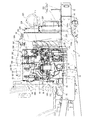
- the DPF 52 includes temperature sensors 186 and 187 that detect the temperature of exhaust gas flowing in the gas purification housing 168.
- the temperature sensors 186 and 187 are, for example, thermistor-type temperature sensors, and have wiring connectors 190 and 191 that are inserted into the gas purification housing 168 and output measurement signals.
- the wiring connectors 190 and 191 of the temperature sensors 186 and 187 are fixed to the hot water pipe fixing bracket 208.
- the hot water pipe bracket 208 has a plate shape bent in an L shape, and is erected from the bent portion 181c of the outlet-side first bracket 181 so as to be parallel to the DPF 52.
- the hot water pipes 203 and 204 are fixed to the left side surface (DPF 52 side) of the hot water pipe fixing bracket 208, while the wiring connectors 190 and 191 are fixed to the right side surface (opposite side of the DPF 52) of the hot water pipe fixing bracket 208.
- DPF 52 side By providing the DPF 52 side with the hot water pipes 203 and 204 for supplying the cooling water (warm water) after cooling contribution to the engine 5 to the external device such as the air conditioner 364, it is possible to prevent the temperature of the cooling water supplied to the external device from being lowered. .
- a heat shielding effect against the exhaust heat from the DPF 52 is obtained by standing on the outer surface of the hot water pipe fixing bracket 208.
- the wiring connectors 190 and 191 which are electrical components can be arranged on the opposite side of the DPF 52 with the hot water pipe fixing bracket 208 interposed therebetween, the influence of exhaust heat from the engine 5 and the DPF 52 can be reduced, and failure due to heating can be prevented at the same time. , Noise superposition in the output signal can be suppressed.
- the DPF 52 has a soot of the gas purification housing 168 so that the differential pressure sensor 192 detects a pressure difference between the upstream side and the downstream side across the soot filter 164.
- Sensor pipes 188 and 189 are connected to the front and rear positions of the filter 164.
- the accumulated amount of particulate matter in the soot filter 164 is converted based on the pressure difference detected by the differential pressure sensor 192 so that the clogged state in the DPF 52 can be grasped.
- a sensor bracket 209 for attaching a differential pressure sensor 192 is installed on a fan shroud 234 that is disposed in front of the engine 5 and surrounds the cooling fan 59.
- the sensor bracket 209 is provided so as to project rearward from the rear surface of the fan shroud 234, and is disposed at a position above the sensor boss body 175 connected to the sensor pipes 188 and 189 and on the right side of the DPF 52. Yes.
- the differential pressure sensor 192 is fixed to the upper surface of the sensor bracket 209, and the sensor pipes 188 and 189 are connected from the lower side of the sensor bracket 209. In the present embodiment, the differential pressure sensor 192 fixed to the sensor bracket 209 is disposed at a position higher than the DPF 52.
- the sensor 192 for measuring the internal environment in the DPF 52 is fixed above the fan shroud 234, the sensor 192 can be arranged on the upstream side in the flow direction of the cooling air in the engine room. Therefore, the influence of exhaust heat from the engine 5 and the DPF 52 can be reduced, and the failure of the sensor 192 due to heating can be prevented. Therefore, the engine 5 can be optimally controlled by properly grasping the internal environment of the DPF 52.
- the exhaust gas outlet pipe 162 of the DPF 52 is provided on the cooling fan 59 side, and the pressure sensor 63 for measuring the pressure difference before and after the purification filter 164 provided in the DPF 52 is fixed above the fan shroud 234.
- a pressure sensor 63 that measures the pressure before and after the purification filter 164 provided on the exhaust outlet side of the DPF 52 in the direction along the output shaft 53 of the engine 5 can be disposed above the fan shroud 234 near the exhaust outlet. Accordingly, since the pressure measurement pipes 188 and 189 provided between the pressure sensor 63 and the DPF 52 can be shortened, measurement errors due to the pressure sensor 234 can be reduced.
- an exhaust pipe 227 is connected to an exhaust gas outlet pipe 162 provided upward on the front right side of the outer peripheral surface of the DPF 52.
- the exhaust pipe 227 is bent rearward along the exhaust gas flow direction, and is arranged to be parallel to the DPF 52. Further, the exhaust pipe 227 is bent downward on the downstream side of the exhaust gas flow so that the exhaust gas discharge port faces downward.
- the exhaust gas exhaust port of the exhaust pipe 227 is inserted into the exhaust gas intake port of the tail pipe 229 fixed to the cabin 7.
- a fixing connecting member 210a is provided on the outer periphery of the middle part of the exhaust pipe 227.
- the exhaust pipe 227 is supported by the engine 5 by connecting the fixing connecting member 210 a to the bracket connecting portion 178 b of the fixing bracket 178 via the exhaust pipe fixing bracket 210.
- the tractor 1 is connected to the exhaust gas outlet pipe 162 of the DPF 52 and is fixed to the engine 5, and an exhaust pipe (first exhaust pipe) 227 is provided on the downstream side of the exhaust pipe 227 and is fixed to the traveling machine body 2.
- the inner diameter of the tail pipe 229 is made larger than the outer diameter of the exhaust pipe 227, and the exhaust outlet side of the exhaust pipe 227 is inserted into the exhaust inlet of the tail pipe 229 for communication. Since the exhaust pipe 227 and the tail pipe 229 are connected and fixed to the engine 5, the traveling machine body 2 and the cabin 7 which are different vibration systems, damage to the exhaust pipe 227 and the tail pipe 229 can be prevented.
- the tail pipe 229 can introduce outside air together with the exhaust gas from the exhaust pipe 227, and the exhaust gas discharged to the outside. Can be cooled.
- a tail pipe 229 configured in a U shape is fixed in front of the control seat 8. That is, the tail pipe 229 is connected and fixed to the front lower side of the cabin frame 300 of the cabin 7 via the fixing bracket 229a.
- the cabin 7 is fixedly supported at the four corners below the cabin frame 300 by a front support 96 and a rear support 97 installed on the traveling machine body. Further, a battery 272 for supplying power is provided on the lower right side of the cabin 7.
- a drain hole 229b for drainage is provided below the tail pipe 229, and a wind direction plate 229c covering the lower side of the drain hole 229b from the rear is connected to the lower side of the tail pipe 229.
- the drain hole 229b By covering the drain hole 229b with the wind direction plate 229c, the drain hole 229b can be drained forward (in the direction away from the cabin 7) without being covered by the wind direction plate 229b.
- the drain hole 229b is provided on the inner side (left side) of the battery 272, and the wind direction plate 229 covers the left and right sides and the rear side (three directions other than the front side) of the drain hole 229b.
- the exhaust gas outlet pipe 162 and the exhaust gas inlet pipe 161 of the DPF 52 are respectively arranged in the front-rear direction so that the exhaust gas from the five engines flows along the output shaft of the engine 5 in the exhaust gas purification device (DPF) 52. is doing.
- the exhaust inlet of the exhaust pipe (first exhaust pipe) 227 is connected to the exhaust gas outlet pipe 162 disposed on the front side of the DPF 52.
- the exhaust pipe (first exhaust pipe) 227 is arranged in parallel with the DPF 52 above the engine 5 toward the rear, and the DPF 52 and the exhaust pipe (first exhaust pipe) 227 are covered with a heat shield plate 250.
- the tractor 1 of this embodiment includes an air conditioning compressor 211 that compresses the refrigerant supplied to the air conditioner 364 of the cabin 7.
- the air-conditioning compressor 211 is driven by the engine 5 through the power transmission from the front end side of the output shaft 53 of the engine 5 via the compressor V-belt 72c.
- the air conditioning compressor 211 is disposed at a position higher than the cooling water pump 71 on the right front side of the engine 5.
- the air conditioning compressor 211 is placed on a compressor fixing bracket 212 having one end connected to an extension bracket 64a connected in front of the fuel supply pump 64.
- the compressor fixing bracket 212 has a shape bent in an L shape, and the air conditioning compressor 211 is fixedly disposed on the upper surface thereof.
- the compressor fixing bracket 212 has its lower end connected to the extension bracket 64a and its upper other end connected to the base end side component connecting portion 181b in the base end portion 181a of the outlet side first bracket 181 so that the engine 5 It is supported by.
- a pulley 213 for pulling the compressor V-belt 72c is disposed on the left side in front of the engine 5.
- a pulley 213 around which the compressor V-belt 72c is wound is fixed to the front edge of the position adjustment bracket 214 that is connected to the thermostat case 71 and protrudes in front of the engine 5 so that the position can be adjusted.
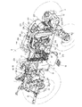
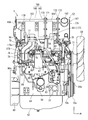
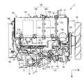
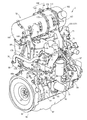
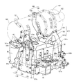
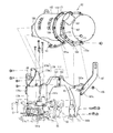
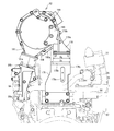
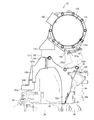
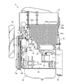
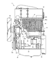
- FIG. 23 A schematic structure of the common rail type diesel engine 5 mounted on the work vehicle will be described with reference to FIGS. 23 to 31.
- FIG. In the following description, both sides along the output shaft 53 (both sides sandwiching the output shaft 53) are left and right, the cooling fan 59 arrangement side is the front side, the flywheel 61 arrangement side is the rear side, and the exhaust manifold 57 arrangement side is The left side and the side on which the intake manifold 56 is arranged are referred to as the right side, and these are used as a reference for the positional relationship between the four sides and the top and bottom in the diesel engine 5 for convenience.
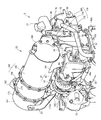
- the diesel engine 5 as a prime mover mounted on a work vehicle such as a tractor includes a continuous regeneration type exhaust gas purification device (DPF) 52.
- the exhaust gas purification device 52 removes particulate matter (PM) in the exhaust gas discharged from the diesel engine 5 and reduces carbon monoxide (CO) and hydrocarbons (HC) in the exhaust gas. .
- the diesel engine 5 includes a cylinder block 54 that incorporates an output shaft 53 (crankshaft) and a piston (not shown).
- a cylinder head 55 is mounted on the cylinder block 54.
- An intake manifold 56 is disposed on the right side surface of the cylinder head 55.
- An exhaust manifold 57 is disposed on the left side surface of the cylinder head 55. That is, in the diesel engine 5, the intake manifold 56 and the exhaust manifold 57 are distributed and arranged on both side surfaces along the output shaft 53.
- a head cover 58 is disposed on the upper surface of the cylinder head 55.
- a cooling fan 59 is provided on one side of the diesel engine 5 that intersects with the output shaft 53, specifically on the front surface of the cylinder block 54. Rotational power is transmitted from the front end side of the output shaft 53 to the cooling fan 59 via the cooling fan V-belt 72a.
- the flywheel housing 60 is provided on the rear surface of the cylinder block 54.
- a flywheel 61 is disposed in the flywheel housing 60.
- a flywheel 61 is pivotally supported on the rear end side of the output shaft 53.
- the power of the diesel engine 5 is taken out via the output shaft 53 to the working part of the work vehicle.
- An oil pan 62 is disposed on the lower surface of the cylinder block 54. Lubricating oil in the oil pan 62 is supplied to each lubricating portion of the diesel engine 5 through an oil filter 63 disposed on the right side surface of the cylinder block 54.
- the oil filter 63 is attached to the right side surface of the cylinder block 54 via an oil filter support member 88.
- a fuel supply pump 64 for supplying fuel is mounted on the right side surface of the cylinder block 54 above the oil filter 63 (below the intake manifold 56).
- a four-cylinder injector 65 with an electromagnetic opening / closing control type fuel injection valve is provided in the diesel engine 5.
- a fuel tank 11 (see FIGS. 1 to 3) mounted on the work vehicle is connected to each injector 65 via a fuel supply pump 64, a cylindrical common rail 66, and a fuel filter 67.
- An oil cooler 68 is disposed on the right side surface of the cylinder block 54 at a position sandwiched between the common rail 66 and the oil filter 63.
- Fuel in the fuel tank 11 is pumped from the fuel supply pump 64 to the common rail 66 through the fuel filter 67, and high-pressure fuel is stored in the common rail 66.
- the fuel injection valve of each injector 65 By controlling the fuel injection valve of each injector 65 to open and close, the high-pressure fuel in the common rail 66 is injected from each injector 65 to each cylinder of the diesel engine 5.
- An engine starter 69 is provided in the flywheel housing 60.
- the pinion gear of the starter 69 for starting the engine meshes with the ring gear of the flywheel 61.
- the output shaft 53 starts to rotate (so-called cranking is executed) by rotating the ring gear of the flywheel 61 with the rotational force of the starter 69.
- a cooling water pump 71 for lubricating lubricating water is arranged coaxially with the fan shaft of the cooling fan 59 on the front side (cooling fan 59 side) of the cylinder head 55.
- the cooling water pump 71 is configured to be driven together with the cooling fan 59 by the rotation of the engine output shaft 53.
- Cooling water in a radiator 235 (see FIGS. 4 and 13) mounted on the work vehicle is supplied to the cooling water pump 71 via a thermostat case 70 provided on the upper part of the cooling water pump 71.
- cooling water is supplied to a water cooling jacket (not shown) formed in the cylinder head 55 and the cylinder block 56 to cool the diesel engine 5. Cooling water that has contributed to cooling the diesel engine 5 is returned to the radiator 235.
- the cooling water pump 71 faces the cooling fan 59 in the positional relationship, and the cooling air from the cooling fan 59 strikes the cooling water pump 71.
- An alternator 73 is provided on the left side of the diesel engine 5, specifically on the left side of the cooling water pump 71, as a generator that generates power using the power of the diesel engine 5. Rotational power is transmitted from the front end side of the output shaft 3 to the cooling fan 59 and the cooling water pump 71 via the cooling fan V belt 72a. Further, rotational power is transmitted to the alternator 73 from the front end side of the output shaft 53 via the alternator V-belt 72b. Cooling water in a radiator 235 (see FIGS. 4 and 26) mounted on the work vehicle is supplied to the cylinder block 54 and the cylinder head 55 by driving of the cooling water pump 71 to cool the diesel engine 5.
- the engine leg mounting portions 74 are provided on the left and right side surfaces of the cylinder block 54, respectively. Each engine leg mounting portion 74 can be bolted to a front engine leg (engine mount) 238 (see FIGS. 1 and 2) having vibration-proof rubber.
- an engine leg mounting portion 74 on the cylinder block 54 side is provided on each engine frame 14 so that the cylinder block 54 is sandwiched between a pair of left and right engine frames 14 (see FIGS. 1 to 3) in the work vehicle. Tighten the bolts via Thereby, both engine frames 14 of the work vehicle support the diesel engine 5 front side.
- An intake communication pipe 76 to which fresh air (external air) is supplied is connected to the right side inlet of the intake manifold 56, and an intake throttle member 77 is provided on the intake inlet side (upstream side) of the intake communication pipe 76.
- a recirculation exhaust gas pipe 78 to which a part of exhaust gas (EGR gas) of the diesel engine 5 is supplied is connected to an upper surface inlet portion of the intake manifold 56 through an EGR valve member 79.
- the intake outlet side (downstream side) of the intake communication pipe 76 and the connection part (rear part) with the EGR valve member 79 are configured as a main body case of the EGR device (exhaust gas recirculation device) 75. Yes.
- the intake intake side of the intake manifold 56 constitutes an EGR main body case.
- the EGR device (exhaust gas recirculation device) 75 is mainly located on the right side of the diesel engine 5, specifically, on the right side of the cylinder head 55, and a part of the exhaust gas (EGR gas) of the diesel engine 5 and new The air is mixed and supplied to the intake manifold 56.
- the EGR device (exhaust gas recirculation device) 75 includes an EGR main body case constituted by a part of the intake manifold 56, an intake communication pipe 76 communicating with the intake manifold 56, and an intake throttle member 77 provided in the intake communication pipe 76.
- the recirculation exhaust gas pipe 78 connected to the exhaust manifold 57 via the EGR cooler 80 and the EGR valve member 79 for communicating the intake manifold 56 with the recirculation exhaust gas pipe 78 are provided.
- An intake throttle member 77 is connected to the intake intake side of the intake manifold 56 through an intake communication pipe 76.
- the outlet side of the recirculated exhaust gas pipe 78 is also connected to the intake intake side of the intake manifold 56 via an EGR valve member 79.
- the inlet side of the recirculation exhaust gas pipe 78 is connected to the exhaust manifold 57 via the EGR cooler 80.
- fresh air is supplied to the intake intake side of the intake manifold 56 via the intake communication pipe 76 and the intake throttle member 77, while EGR gas is supplied from the exhaust manifold 57 to the intake intake side of the intake manifold 56.
- Fresh air from the outside and EGR gas from the exhaust manifold 57 are mixed on the intake intake side of the intake manifold 56.
- a turbocharger 81 is disposed on the left side of the cylinder head 5 and above the exhaust manifold 57.
- the turbocharger 81 includes a turbine case 82 with a built-in turbine wheel and a compressor case 83 with a blower wheel.
- the exhaust intake side of the turbine case 81 is connected to the outlet of the exhaust manifold 57.
- the exhaust discharge side of the turbine case 81 is connected to the exhaust intake side of the exhaust gas purification device 52 via the exhaust communication pipe 84. That is, the exhaust gas discharged from each cylinder of the diesel engine 5 to the exhaust manifold 7 is discharged to the outside via the turbocharger 81, the exhaust gas purification device 52, and the like.
- the intake side of the compressor case 83 is connected to the intake / discharge side of an air cleaner 221 (see FIGS. 4 and 13) via an air supply pipe 222 (see FIGS. 4 and 13).
- the intake discharge side of the compressor case 83 is connected to the intake intake side of the intercooler 224 (see FIGS. 4 and 13) via an upstream relay pipe 223 (see FIGS. 4 and 13).
- the intake air discharge side of the intercooler 224 (see FIGS. 4 and 15) is connected to the intake throttle member 77 via a downstream relay pipe 225 (see FIGS. 4 and 15). That is, fresh air (external air) removed by the air cleaner 221 is sent from the compressor case 83 to the EGR device 75 via the intercooler 224 and then supplied to each cylinder of the diesel engine 5.
- An exhaust gas purifying device 52 is disposed on the upper surface side of the diesel engine 5 above the exhaust manifold 57 and the turbocharger 81, that is, above the exhaust manifold 57 and the turbocharger 81 on the left side of the cylinder head 55. ing. In this case, the attitude of the exhaust gas purification device 52 is set so that the longitudinal direction of the exhaust gas purification device 52 extends in parallel with the output shaft 53 of the diesel engine 5.
- the DPF 52 is for collecting particulate matter (PM) and the like in the exhaust gas.
- the DPF 52 is configured in a substantially cylindrical shape extending in the front-rear direction in parallel with the output shaft (crankshaft) 53 of the diesel engine 5.
- a DPF 52 is disposed above the cylinder head 55 of the diesel engine 5.
- An exhaust gas inlet pipe 161 (exhaust gas intake side) and an exhaust gas outlet pipe 162 (exhaust gas discharge side) are connected to both sides of the DPF 52 (one end side and the other end side in the exhaust gas movement direction) of the diesel engine 5. Distribute before and after.
- the DPF 52 has a structure in which, for example, a diesel oxidation catalyst 163 such as platinum and a soot filter 164 having a honeycomb structure are arranged in series and accommodated therein.
- a diesel oxidation catalyst 163 such as platinum
- a soot filter 164 having a honeycomb structure
- nitrogen dioxide (NO 2) generated by the oxidation action of the diesel oxidation catalyst 163 is taken into the soot filter 164.
- Particulate matter contained in the exhaust gas of the diesel engine 5 is collected by the soot filter 164 and continuously oxidized and removed by nitrogen dioxide (NO 2). Therefore, in addition to the removal of particulate matter (PM) in the exhaust gas of the diesel engine 5, the content of carbon monoxide (CO) and hydrocarbon (HC) in the exhaust gas of the engine 1 is reduced.
- the diesel oxidation catalyst 163 and the soot filter 164 correspond to a gas purification filter accommodated in the purification housing 38.
- the DPF 52 includes an upstream case (first case) 165 having an exhaust gas inlet pipe 161 on the outer peripheral surface, an intermediate case (second case) 166 connected to the exhaust inlet side case 165, and an exhaust outlet pipe 162 having an outer peripheral surface. And a downstream case (third case) 167 to be inserted.
- An upstream case 165 and an intermediate case 166 are connected in series to constitute a gas purification housing 168 made of a heat-resistant metal material.
- the gas purification housing 168 accommodates a diesel oxidation catalyst 163 and a soot filter 164 via a cylindrical inner case (not shown).
- the downstream case 168 includes an inner case (not shown) in which a number of silencer holes are opened, and a silencer made of ceramic fiber is filled between the inner case and the silencer to form a silencer. ing.
- the upstream case 165 has one end that is upstream in the exhaust gas movement direction covered with an upstream lid 169 and the other end that is downstream in the exhaust gas movement is open, and the exhaust gas movement direction It has a cylindrical shape with an opening on the downstream side.
- the intermediate case 166 has a cylindrical shape with both ends opened.
- the downstream case 167 opens one end that is upstream in the exhaust gas movement direction, and covers the other end that is downstream in the exhaust gas movement direction with a downstream lid 174, and is upstream in the exhaust gas movement direction. It is comprised by the cylindrical shape which opened.
- a tail pipe 229 (see FIGS. 4 and 21) is connected to an exhaust gas outlet pipe 162 provided on the outer peripheral surface of the downstream case 167 via an exhaust pipe 227 (see FIGS. 4 and 21). Exhaust gas is discharged from the exhaust gas outlet pipe 162 through the exhaust pipe 227 and the tail pipe 229 to the outside.
- the connecting portion of the upstream case 165 and the intermediate case 166 is connected by being sandwiched from both sides in the exhaust gas movement direction by a pair of thick plate-like holding flanges 170 and 171. That is, the joining flange provided at the downstream opening edge of the upstream case 165 and the joining flange provided at the upstream opening edge of the intermediate case 166 are sandwiched by the sandwiching flanges 170 and 171, so that the upstream case 165
- the gas purification housing 168 is configured by connecting the downstream side and the upstream side of the intermediate case 166. At this time, the upstream side case 165 and the intermediate case 166 are detachably connected by fastening the center clamping flanges 170 and 171 with bolts.
- the connecting portion of the intermediate case 166 and the downstream case 167 is connected by being sandwiched from both sides in the exhaust gas movement direction by a pair of thick plate-like holding flanges 172 and 173. That is, the joining flange provided at the downstream opening edge of the intermediate case 166 and the joining flange provided at the upstream opening edge of the downstream case 167 are sandwiched by the sandwiching flanges 172 and 173, and the downstream of the intermediate case 166.
- the gas purification housing 168 is configured by connecting the side and the upstream side of the downstream case 167. At this time, the intermediate case 166 and the flow side case 167 are detachably connected by fastening the outlet side clamping flanges 172 and 173 with bolts.
- An exhaust gas inlet pipe 161 is provided on the outer peripheral portion of the upstream case 165 on the exhaust intake side (exhaust inlet side), and the exhaust intake side of the exhaust gas inlet pipe 161 has an exhaust communication pipe 84 as an exhaust relay path. And communicates with the exhaust discharge side of the turbine case 82.
- the exhaust communication pipe 84 has a substantially L-shape when viewed from the side.
- the exhaust communication pipe 84 is provided with the exhaust intake side in front and is connected to the exhaust discharge side of the turbine case 82, while the exhaust discharge side is provided upward and the DPF 52.
- the exhaust gas inlet pipe 161 is connected.
- the exhaust communication pipe 84 includes a connection support portion 84 a extending from the outer peripheral surface side to the lower side, and the lower end of the connection support portion 82 a is connected to the left side surface of the exhaust manifold 57. That is, the exhaust communication pipe 84 is fixed to the diesel engine 5 by being bolted to the exhaust manifold 57 and the turbine supercharger 81.
- a sensor boss body 175 connected to the temperature sensors 186 and 187 (see FIGS. 21 and 22) and the sensor pipes 188 and 189 (see FIG. 15) is provided on the outer peripheral surface of the gas purification housing 168.
- the upstream case 165 accommodates the upstream portion of the oxidation catalyst 163 and the soot filter 164
- the intermediate case 165 accommodates the downstream portion of the soot filter 164.
- a sensor boss body 175 connected to the upstream temperature sensor 186 is provided on the outer peripheral surface of the upstream case 165 at a position upstream of the oxidation catalyst 163 in the exhaust gas movement direction, and the oxidation catalyst 163 and the soot filter 164 are connected to each other.
- a sensor boss body 175 connected to the downstream temperature sensor 187 and the upstream sensor pipe 188 is provided at a position in between.
- a sensor boss body 175 connected to the downstream sensor pipe 189 is provided on the outer peripheral surface of the intermediate case 166 at a position downstream of the soot filter 164 in the exhaust gas movement direction.
- the diesel engine 5 includes an inlet side bracket body 176 and an outlet side bracket body 177 as a housing support body that supports and fixes the exhaust gas purification device 52 (gas purification housing 168).
- the inlet side bracket body 176 and the outlet side bracket body 177 are formed wide in a direction intersecting with the output shaft 53 of the diesel engine 5.
- the inlet side bracket body 176 and the outlet side bracket body 177 are detachably connected to the cylinder head 55 of the diesel engine 5 directly or via the intake manifold 56 or the exhaust manifold 57.
- the inlet side bracket body 176 and the outlet side bracket body 177 are arranged upright on the front side and the rear side that intersect the output shaft 53 in the cylinder head 55.
- the inlet side bracket body 176 is located on the rear surface side of the cylinder head 55 and supports the exhaust gas intake side of the gas purification housing 168.
- the outlet side bracket body 177 is located on the front side of the cylinder head 55 and supports the exhaust discharge side of the gas purification housing 168.
- the inlet side bracket body 176 is located on the rear side of the cylinder head 55 (above the flywheel housing 60).
- the inlet side bracket body 176 has a lower end side of the fixed bracket (first bracket) 178 fastened to the rear surface of the cylinder head 5 with a bolt.
- a relay bracket 179 is bolted to the upper end side of the fixed bracket 178.
- the proximal end side of the extension bracket (third bracket) 180 is bolted to the middle portion of the relay bracket (second bracket) 179, and the distal end side of the extension bracket 180 is the inlet of the gas purification housing 168 via the bolt and nut. Fastened to the side lid (upstream lid) 169.
- the outlet side bracket body 177 is located on the front side of the cylinder head 55 (on the cooling fan 59 side).
- the outlet side bracket body 177 of the embodiment is configured to be divided into an outlet side first bracket (fourth bracket) 181 and an outlet side second bracket (fifth bracket) 182.
- the outlet-side first bracket 181 is formed of a substantially L-shaped member that extends upward from the right side of the cylinder head 55 and is bent leftward above the cylinder head 55.
- the outlet-side second bracket 182 is configured by a substantially L-shaped member that extends upward from the left side of the cylinder head 55 and is bent rightward above the cylinder head 55. Therefore, the outlet side bracket body 177 has a substantially portal shape on the front surface side of the cylinder head 55 and is fixed so as to straddle the cylinder head 55 at the rear position of the thermostat case 70.
- the lower end surface (base end side) of the outlet side first bracket 181 is bolted to the upper surface side of the intake manifold 56, and the upper left side surface (tip end side) of the outlet side first bracket 181 is connected to the outlet side second bracket 182.
- Bolts are fastened to the upper right side (front end side).
- the lower right side surface (base end side) of the outlet-side second bracket 182 is bolted to the front portion of the left side surface of the cylinder head 55.
- An upper end curved surface (U-shaped pressure receiving surface) 182 a that receives the outer peripheral surface of the gas purification housing 168 is provided on the upper end side (tip side) of the outlet-side second bracket 182, and a sandwiching flange (outlet clamping flange) in the gas purification housing 168 )
- a bolt is fastened to a bracket fastening portion 172a formed on the lower side of 172.
- the exhaust gas purifying device 52 of the embodiment is disposed above the diesel engine 4 via the exhaust communication pipe 84, the inlet side bracket body 176, and the outlet side bracket body 177, which are housing supports.
- the cylinder head 55, the intake manifold 56 and the exhaust manifold 57 of the engine 1 are detachably connected.
- the inlet side bracket body 176 and the exhaust communication pipe 84 on the upstream side (exhaust intake side) in the exhaust gas movement direction are distributed to the cylinder head 55 and the exhaust manifold 57, and downstream in the exhaust gas movement direction (exhaust exhaust side).
- the exhaust gas purification device 52 can be supported with high rigidity as one of the components of the engine 5, and damage to the exhaust gas purification device 52 due to vibration or the like can be prevented.
- the reference mounting position of the exhaust gas purifying device 52 with respect to the engine 5 can be set with high accuracy. For this reason, even if the exhaust gas purifying device 52 is heavier than a muffler or the like as a post-processing device, it can be properly mounted at a predetermined position.
- the fixing bracket 178 is configured as a plate-like body having a wide crossing direction with the exhaust gas movement direction of the DPF 1 (the output shaft 53 of the diesel engine 5).
- the lower part of the recirculation exhaust gas pipe 78 is bolted to the cylinder head 55. That is, the recirculation exhaust gas pipe 78 connected to the EGR cooler 80 bypasses the rear of the fixed bracket 178 and is connected to the intake throttle member 77.
- the fixed bracket 178 includes a front part connecting part (first part connecting part) 178a having a bolt hole in an upper part of the recirculation exhaust gas pipe 78, and is suspended from the hanging metal fitting connecting part 178a.
- the metal fitting 86 is detachably bolted.
- the fixed bracket 178 includes a bracket connecting portion 178b having a bolt hole on the upper surface of the upper end portion, and the relay bracket 179 is detachably bolted to the bracket connecting portion 178b.
- the fixing bracket 178 includes a side part connecting part (second part connecting part) 178c having a bolt hole on the right side surface of the upper end portion, and the side part connecting part 178c includes, for example, an exhaust pipe.
- a component fixing bracket (exhaust pipe fixing bracket) 210 (see FIGS. 20 and 21) for fixing external components such as 227 (see FIGS. 20 and 21) is bolted.
- the relay bracket 179 is bolted to the fixing bracket 178 with the bottom surface of the lower end portion abutting against the bracket connecting portion 178 b of the upper surface of the upper end portion of the fixing bracket 178.
- a base plate 179a extending upward from a lower end portion fixed to the bracket connecting portion 178b of the fixed bracket 178 is welded with a connecting plate 179b standing rearward with respect to the plate 179a. It has a configuration.
- the connecting plate 179b of the relay bracket 179 has a front / rear position adjusting bolt hole that is long in the front / rear direction.
- the extension bracket 180 has a configuration in which a connection portion with the relay bracket 179 is erected rearward from a fixing portion with the upstream cover body 169 of the gas purification housing 168.
- the exhaust communication pipe 84 is configured as a housing support body that supports the inlet side of the gas purification housing 168 together with the inlet side bracket body 176.
- the exhaust gas inlet side of the DPF 52 has an inlet side bracket body 176 connected to the rear surface of the cylinder head 55 and the inlet side cover body 169, and an exhaust communication pipe 84 connected to the left side surface of the exhaust manifold 57 and the exhaust gas inlet pipe 161, respectively. And is supported with high rigidity.
- an embedded bolt 85 is provided on the upward mounting surface 84b of the exhaust communication pipe 84.
- the inlet flange body 161a of the exhaust gas inlet pipe 161 is formed with a front / rear position adjusting bolt hole that is long in the front / rear direction.
- the embedded bolt 85 is passed through the inlet flange body 161a of the exhaust gas inlet pipe 161 from below so as to be loosely fitted, and a nut 85a is screwed to the upper end side of the embedded bolt 85, and the exhaust gas inlet pipe 161 is attached to and detached from the housing support 85. Conclude it as possible.
- the attachment position of the DPF 52 in the front-rear direction relative to the exhaust communication pipe 84 can be adjusted by the dimension that the embedded bolt 85 moves back and forth in the bolt hole that is long in the front-rear direction in the inlet flange body 161a.
- the exhaust communication pipe 84 and the inlet side bracket body 176 are moved back and forth.
- the mounting position in the front-rear direction of the rear portion of the gas purification housing 168 can be adjusted. Accordingly, the assembly position of the DPF 52 with respect to the diesel engine 5 can be easily determined, and the assembly accuracy of the DPF 52 to be fixed to the diesel engine 5 can be improved. Further, it is possible to prevent the deformation force from acting on the gas purification housing 168 due to the connection position error of the exhaust communication pipe 84, the inlet side bracket body 176, and the outlet side bracket body 177. That is, even if the DPF 52 is provided at a position where the diesel engine 5 is easily shaken, the mechanical vibration of the DPF 52 can be easily reduced.
- the exhaust communication pipe 84 has an exhaust gas discharge side (exhaust outlet side) extended upward with respect to the connection support portion 84 a fastened to the exhaust manifold 57, and a right side (cylinder head 55) with respect to the vertical direction (vertical direction). Side). That is, when the exhaust communication pipe 84 is viewed from the back, the exhaust communication pipe 84 has the upward mounting surface 84b located on the right side to the right side of the connection portion with the exhaust manifold 57 by the connection support portion 84a.
- the exhaust communication pipe 84 is formed so that the upward mounting surface 84b is inclined from the horizontal plane so that the right edge is on the lower side, and the upper end of the embedded bolt 85 is inclined to the right side.
- the DPF 52 is lowered from the upper right side to the lower left side with respect to the exhaust communication pipe 84.
- the bolts of the inlet flange body of the exhaust gas inlet pipe 161 can be fitted to the embedded bolts 85 of the inclined exhaust communication pipe 84 by loosely fitting the mounting bolts to be screwed to the fixing bracket 178 to the relay bracket 179.
- the width Dx of the bracket connecting portion 178b on the upper surface of the fixed bracket 178 is made wider than the width Dy of the lower end of the relay bracket 179. That is, when the DPF 52 is lowered obliquely and placed on the diesel engine 5 so as to connect the exhaust gas inlet pipe 161 to the exhaust communication pipe 84, the relay bracket 179 is surely secured by the bracket connecting portion 178b on the upper surface of the fixed bracket 178. Can receive the entire bottom edge.
- the base end 181 a of the outlet-side first bracket 181 is vertically moved to insert a mounting bolt to be screwed into a bolt hole provided on the upper surface of the intake manifold 56.
- a plurality of through holes are provided.
- a component fixing bracket (compressor fixing bracket) 212 (FIG. 16) for fixing external components such as an air conditioning compressor 211 (see FIGS. 16 and 22), for example, is provided at the base end portion 181a of the outlet-side first bracket 181.
- the base end side component connection part (3rd component connection part) 181b which fixes (refer FIG. 22) is provided.
- the base end side component connecting portion 181b is provided with a part of a through hole into which the mounting bolt is inserted and a bolt hole into which a mounting bolt for fastening the component fixing bracket 212 is screwed. That is, the component fixing bracket 212 is fastened to the outlet-side first bracket 181 with a mounting bolt, and at the same time, together with the outlet-side first bracket 181 with a mounting bolt that is screwed through the through hole of the base-end-side component connecting portion 181b. Fasten to intake manifold 56.
- Component fixing for fixing external components such as air-conditioning hot water pipes 203 and 204 (see FIGS. 18, 21, and 22), for example, on the upper surface of the bent portion (midway portion) 181c of the outlet-side first bracket 181
- An intermediate part connecting part (fourth part connecting part) 181d for fixing the working bracket (warm water pipe fixing bracket) 208 (see FIGS. 18, 21, and 22) is provided.
- a flat step is provided in the bent portion 181c of the outlet-side first bracket 181 and a bolt hole is provided on the upper surface of the step so that a mounting bolt for fastening the component fixing bracket 208 is screwed.
- a midway part connecting portion 181d is provided.
- the base end 182 b of the outlet-side second bracket 182 has left and right mounting bolts that are screwed into bolt holes provided on the left side surface of the intake manifold 56. A plurality of through-holes penetrating through are provided.
- the bent part (midway part) 182c of the outlet-side second bracket 182 is provided with a rear part connecting part (fifth part connecting part) 182d having a bolt hole on the rear surface side, and is suspended from the rear part connecting part 182d.
- the lowering metal fitting 87 is detachably bolted.
- the outlet-side second bracket 182 has an upper end curved surface (U-shaped pressure receiving surface) 182a corresponding to the outer shape of the gas purification housing 168 at the upper end portion from the bent portion 182c toward the right end.
- an embedded bolt 183 as a locking shaft body is provided at the central portion on the upper end side of the outlet-side second bracket 182.
- the embedded bolt 183 protrudes forward from the front surface of the central portion on the upper end side of the outlet-side second bracket 182.
- the bracket fastening portion 172a of the outlet pinching flange 172 in the gas purification housing 168 is formed with a bolt opening notch 184 having a downward opening as a locking shaft (concave).
- the bolt hole for inserting the embedded bolt 183 formed in the bracket fastening portion 172a of the outlet clamping flange 172 is cut open upward to form a bolt insertion notch 228.
- the embedded bolt 183 of the outlet side second bracket 182 can be locked to the bolt insertion notch 184 of the bracket fastening portion 172a of the outlet clamping flange 172.
- the bracket 182 supports the downstream side (exhaust discharge side) of the gas purification housing 168 in the exhaust gas movement direction.
- the exhaust discharge side of the gas purification housing 168 is held at a predetermined position. That is, the relay bracket 179 attached to the gas purification housing 168 via the extension bracket 180 is placed on the upper end side of the fixed bracket 178, and the exhaust intake side of the exhaust gas inlet pipe 161 is connected to the upper end side of the exhaust communication pipe 84 (exhaust exhaust gas).
- the inlet side bracket body 176 and the outlet side bracket body 177 by engaging the notch 184 for inserting the bolt on the gas purification housing 168 side with the embedded bolt 183 on the outlet side second bracket 182 side.
- the gas purification housing 168 is temporarily fixed.
- the mounting position of the exhaust gas purification device 52 with respect to the diesel engine 5 can be easily positioned, and the worker who performs the assembly work can release both hands from the exhaust gas purification device 52 in the temporarily fixed state. Therefore, it is not necessary to perform assembly work such as bolt fastening or removal work while supporting the entire weight of the exhaust gas treatment device 52, and when the exhaust gas purification device 52 is loaded or unloaded, or the assembly and disassembly of the exhaust gas purification device 52 is performed. The labor at the time of work can be greatly reduced.
- the embedded bolt 183 may be provided on the gas purification housing 168 side, and the bolt insertion notch 184 may be provided on the outlet side second bracket 182 side.
- Either the outlet side bracket body 177 or the gas purification housing 168 is provided with a convex body (embedded bolt 183) or a concave body (bolt insertion notch 184) as a locking body, and the outlet side bracket body 177 or the gas purification body. Since the concave body (bolt insertion notch 184) or the convex body (embedded bolt 183) is provided on the other side of the housing 168, the embedded bolt 183 (convex body) and the bolt insertion notch 184 are provided. The assembly position of the gas purification housing 168 can be easily determined by the engagement of the (concave body).
- the opening direction of the bolt insertion notch 184 is cut away in a direction in which the inlet flange body 161a of the exhaust gas inlet pipe 161 in the DPF 52 is placed on the upward mounting surface 84b of the exhaust communication pipe 84. That is, the bolt insertion notch 184 is opened in a direction parallel to the inclination direction of the embedded bolt 85 provided on the upward mounting surface 84 b of the exhaust communication pipe 84. Therefore, when the DPF 52 is fixedly supported by the exhaust communication pipe 84, the inlet side bracket body 176, and the outlet side bracket body 177, the bolts for adjusting the position of the inlet flange body 161a in the exhaust gas inlet pipe 161 are inserted into the embedded bolts 85. However, the bolt insertion notch 184 can be easily engaged with the embedded bolt 183, and the assembly / disassembly workability of the DPF 52 can be further improved.
- the upward mounting surface 84b of the exhaust communication pipe 84 and the connecting plate 179b of the relay bracket 179 form a V-shaped pressure receiving surface.
- the exhaust gas outlet side of the DPF 52 is mounted on the U-shaped pressure receiving surface 182 a of the outlet-side second bracket 182. Therefore, when the DPF 52 is temporarily fixed and supported on the exhaust communication pipe 84, the inlet side bracket body 176, and the outlet side bracket body 177, the exhaust gas inlet side and the exhaust gas outlet side of the DPF 52 respectively have a V-shaped pressure receiving surface and a U-type heavy pressure.
- the surface restricts movement in the direction intersecting with the output shaft 53 of the engine 5 and prevents the DPF 52 from falling.
- hanging metal fittings 86 and 87 for hanging a hanging wire or the like are connected to the inlet side bracket body 176 and the outlet side bracket body 177. Therefore, when loading and unloading the diesel engine 5 on the work vehicle, the suspension wires 86 and 87 are respectively inserted into the suspension through holes, and the suspension wires hooked to the hooks of the chain block. The diesel engine 5 can be attached and detached by lifting.
- the hanging fitting 86 is connected to the fixed bracket 178 of the inlet side bracket body 176 located on the right rear side of the diesel engine 5, while the hanging fitting 87 is located on the outlet side located on the left front side of the diesel engine 5.
- the bracket body 177 is connected to the outlet-side second bracket 182. That is, since the suspension fittings 86 and 87 are disposed diagonally with respect to the diesel engine 5, the diesel engine 5 can be suspended by a chain block or the like in a stable posture. Furthermore, by making the hanging fittings 86 and 87 detachable, the hanging fittings 86 and 87 can be removed when the diesel engine 5 is mounted on the work vehicle, and the diesel engine 5 in the engine room of the work vehicle can be removed. The storage capacity can be reduced.
- the shielding plate 205 is disposed on the left side surface of the engine 5 so as to cover from the upper side of the EGR cooler 80 to the lower side of the DPF 52, and a part of the DPF 52, the exhaust manifold 57.
- the turbocharger 81 and the exhaust communication pipe 84 are covered.
- the cooling air induced by the cooling fan 59 in front of the engine 5 is heated and raised by the high heat source component covered with the shielding plate 205 and is guided to the DPF 52.
- the cooling air heated by the exhaust heat of the engine 5 is guided to the DPF 52 by the shielding plate 205, so that the DPF 52 can be disposed in a high temperature environment, and thus the regeneration capacity of the DPF 52 can be prevented from being lowered.
- the shielding plate 205 is constituted by a perforated plate in which a plurality of punch holes 205a are arranged in a matrix. Further, the punch holes 205a are arranged at equal intervals in the upper, lower, left and right directions. Through this punch hole 205 a, a part of the cooling air heated by the engine 5 can be exhausted to the outside through the shielding plate 205 and the engine cover 232. Thereby, by reducing the flow resistance of the space between the side surface of the engine 5 and the shielding plate 205, the generation of turbulent flow in the space can be suppressed.
- FIG. 39A Another configuration example of the shielding plate 205 will be described below with reference to FIG.
- the arrangement density of the punch holes 205 a provided in the shielding plate 205 is changed above and below the shielding plate 205.
- punch holes 205a are provided in the shielding plate 205 so that the opening ratio on the DPF 52 side is higher than the opening ratio on the lower side of the exhaust manifold 57. That is, the shielding plate 205 shortens the pitch (interval) of the adjacent punch holes 205a on the DPF 52 side, and increases the pitch (interval) of the adjacent punch holes 205a on the lower side of the exhaust manifold 57.
- the porous shielding plate 205 by forming the porous shielding plate 205 with the punch holes 205a, not only the opening area of the shielding plate 205 can be easily adjusted, but also the opening region can be designed flexibly. Further, in the shielding plate 205, the opening area on the DPF 5 side is made larger than that on the lower side of the exhaust manifold 57, so that the exhaust heat that has risen is more efficiently guided to the DPF 52, and at the same time, the engine 5 in the opening area on the DPF 52 side. It becomes easy to exhaust a part of the cooling air, and the heat retention between the shielding plate 205 and the engine 5 can also be suppressed.
- the shielding plate 205 is formed of a perforated plate in which elongated holes 205b are arranged.
- the long holes 205b of the shielding plate 205 are holes opened in the vertical direction, and are arranged at equal intervals in the front-rear direction.
- a long hole 205b is provided so that the opening ratio on the DPF 52 side is higher than the opening ratio on the lower side of the exhaust manifold 57. That is, the shielding plate 205 shortens the pitch (interval) of the adjacent long holes 205b on the DPF 52 side, and increases the pitch (interval) of the adjacent long holes 205b on the lower side of the exhaust manifold 57. Further, the shielding plate 205 increases the opening area of one elongated hole 205b on the DPF 52 side, and decreases the opening area of one elongated hole 205b on the lower side of the exhaust manifold 57.
- the configuration of the shielding plate 205 is not limited to the configuration shown in FIGS. 38 and 39.
- the shielding plate 205 is configured by a perforated plate provided with a plurality of elongated holes opened in the left-right direction. It may be.
- FIG. 40 for example, as shown in FIG. 40, the punch holes 205a in FIGS. 38 and 39A and the long holes 205b in FIG. By covering the front side portion of this, the cooling air heated on the side of the engine 5 may be exhausted to the rear left side of the holes 205a and 205b so that the rear left side of the holes 205a and 205b is opened.
- an EGR cooler 80 for cooling a part of the exhaust gas from the exhaust manifold 57 is provided below the exhaust manifold 57, and the outside of the EGR cooler 80 is disposed below the shielding plate 205. It may be configured to cover with a heat shield plate 205c of a metal plate. By covering the outside (left side) of the EGR cooler 80 with a heat shield plate 205c fixed below the shield plate 205, the cooling air from the front of the engine 5 is guided to the EGR cooler 205, while the EGR cooler 80 side. The heated cooling air can be raised toward the upper DPF 52. Therefore, the heat balance in the engine room can be optimized and the exhaust heat from the engine 5 can be efficiently utilized by the DPF 52, while the heat retention around the engine 5 can be suppressed.
Landscapes
- Engineering & Computer Science (AREA)
- Chemical & Material Sciences (AREA)
- Combustion & Propulsion (AREA)
- Mechanical Engineering (AREA)
- Chemical Kinetics & Catalysis (AREA)
- General Engineering & Computer Science (AREA)
- Health & Medical Sciences (AREA)
- Toxicology (AREA)
- Transportation (AREA)
- Physics & Mathematics (AREA)
- Acoustics & Sound (AREA)
- Cooling, Air Intake And Gas Exhaust, And Fuel Tank Arrangements In Propulsion Units (AREA)
Abstract
Le véhicule de travail de l'invention est équipé : d'un moteur (5) chargé sur une partie avant d'un corps mobile ; d'un dispositif de post-traitement (52) purifiant un gaz d'échappement dudit moteur (5) ; et d'un ventilateur de refroidissement (59) destiné à refroidir l'air dudit moteur (5). Ledit ventilateur de refroidissement (59) est disposé côté face avant dudit moteur (5), et ledit ventilateur de refroidissement (59), ledit moteur (5) ainsi que ledit dispositif de post-traitement (52) sont recouverts par un capot (6). Ledit capot (6) est équipé d'une plaque de blindage (205) se trouvant en dessous dudit dispositif de post-traitement (52) et recouvrant un côté dudit moteur (5), et sert de plaque perforée telle qu'une pluralité de trous est agencée dans ladite plaque de blindage (205).
Priority Applications (4)
| Application Number | Priority Date | Filing Date | Title |
|---|---|---|---|
| KR1020177008497A KR101913981B1 (ko) | 2014-10-15 | 2015-10-06 | 작업 차량 |
| CN201580050185.XA CN106794756B (zh) | 2014-10-15 | 2015-10-06 | 作业车辆 |
| EP15851310.1A EP3208126B1 (fr) | 2014-10-15 | 2015-10-06 | Véhicule de travail |
| US15/489,380 US10487711B2 (en) | 2014-10-15 | 2017-04-17 | Work vehicle |
Applications Claiming Priority (4)
| Application Number | Priority Date | Filing Date | Title |
|---|---|---|---|
| JP2014211132 | 2014-10-15 | ||
| JP2014-211132 | 2014-10-15 | ||
| JP2015-079706 | 2015-04-09 | ||
| JP2015079706A JP6438341B2 (ja) | 2014-10-15 | 2015-04-09 | 作業車両 |
Related Child Applications (1)
| Application Number | Title | Priority Date | Filing Date |
|---|---|---|---|
| US15/489,380 Continuation US10487711B2 (en) | 2014-10-15 | 2017-04-17 | Work vehicle |
Publications (1)
| Publication Number | Publication Date |
|---|---|
| WO2016060026A1 true WO2016060026A1 (fr) | 2016-04-21 |
Family
ID=55746573
Family Applications (1)
| Application Number | Title | Priority Date | Filing Date |
|---|---|---|---|
| PCT/JP2015/078379 WO2016060026A1 (fr) | 2014-10-15 | 2015-10-06 | Véhicule de travail |
Country Status (1)
| Country | Link |
|---|---|
| WO (1) | WO2016060026A1 (fr) |
Cited By (3)
| Publication number | Priority date | Publication date | Assignee | Title |
|---|---|---|---|---|
| EP3208439A4 (fr) * | 2014-10-15 | 2017-12-13 | Yanmar Co., Ltd. | Dispositif de moteur |
| JP2021152366A (ja) * | 2016-04-26 | 2021-09-30 | ヤンマーパワーテクノロジー株式会社 | エンジン装置 |
| US20220074330A1 (en) * | 2017-06-15 | 2022-03-10 | Yanmar Power Technology Co., Ltd. | Engine |
Citations (4)
| Publication number | Priority date | Publication date | Assignee | Title |
|---|---|---|---|---|
| JPH0899539A (ja) * | 1994-09-29 | 1996-04-16 | Kubota Corp | 車両のボンネット構造 |
| JP2014025401A (ja) * | 2012-07-26 | 2014-02-06 | Yanmar Co Ltd | エンジン装置 |
| JP2014031053A (ja) * | 2012-08-01 | 2014-02-20 | Yanmar Co Ltd | トラクタ |
| JP2014172465A (ja) * | 2013-03-07 | 2014-09-22 | Kubota Corp | 作業車の排気装置 |
-
2015
- 2015-10-06 WO PCT/JP2015/078379 patent/WO2016060026A1/fr active Application Filing
Patent Citations (4)
| Publication number | Priority date | Publication date | Assignee | Title |
|---|---|---|---|---|
| JPH0899539A (ja) * | 1994-09-29 | 1996-04-16 | Kubota Corp | 車両のボンネット構造 |
| JP2014025401A (ja) * | 2012-07-26 | 2014-02-06 | Yanmar Co Ltd | エンジン装置 |
| JP2014031053A (ja) * | 2012-08-01 | 2014-02-20 | Yanmar Co Ltd | トラクタ |
| JP2014172465A (ja) * | 2013-03-07 | 2014-09-22 | Kubota Corp | 作業車の排気装置 |
Cited By (5)
| Publication number | Priority date | Publication date | Assignee | Title |
|---|---|---|---|---|
| EP3208439A4 (fr) * | 2014-10-15 | 2017-12-13 | Yanmar Co., Ltd. | Dispositif de moteur |
| US10669913B2 (en) | 2014-10-15 | 2020-06-02 | Yanmar Co., Ltd. | Engine apparatus |
| JP2021152366A (ja) * | 2016-04-26 | 2021-09-30 | ヤンマーパワーテクノロジー株式会社 | エンジン装置 |
| US20220074330A1 (en) * | 2017-06-15 | 2022-03-10 | Yanmar Power Technology Co., Ltd. | Engine |
| US11846220B2 (en) * | 2017-06-15 | 2023-12-19 | Yanmar Power Technology Inc., Ltd. | Engine |
Similar Documents
| Publication | Publication Date | Title |
|---|---|---|
| JP6438341B2 (ja) | 作業車両 | |
| JP6498017B2 (ja) | 作業車両 | |
| WO2016059963A1 (fr) | Dispositif de moteur | |
| KR101902718B1 (ko) | 작업 차량 | |
| WO2016060026A1 (fr) | Véhicule de travail | |
| JP6297465B2 (ja) | トラクタ | |
| JP6322118B2 (ja) | エンジン装置 | |
| JP6475569B2 (ja) | エンジン装置 | |
| JP2016078594A (ja) | 作業車両 | |
| JP6401568B2 (ja) | トラクタ | |
| JP6378040B2 (ja) | 作業車両 | |
| JP6305308B2 (ja) | 作業車両 | |
| JP6490384B2 (ja) | 作業車両 | |
| JP2016193626A (ja) | 作業車両 | |
| JP6343221B2 (ja) | エンジン装置 | |
| JP6378035B2 (ja) | トラクタ | |
| JP6391411B2 (ja) | エンジン装置 | |
| JP6347549B2 (ja) | エンジン装置 | |
| JP6309424B2 (ja) | 作業車両 | |
| WO2016060027A1 (fr) | Véhicule de travail |
Legal Events
| Date | Code | Title | Description |
|---|---|---|---|
| 121 | Ep: the epo has been informed by wipo that ep was designated in this application |
Ref document number: 15851310 Country of ref document: EP Kind code of ref document: A1 |
|
| ENP | Entry into the national phase |
Ref document number: 20177008497 Country of ref document: KR Kind code of ref document: A |
|
| NENP | Non-entry into the national phase |
Ref country code: DE |
|
| REEP | Request for entry into the european phase |
Ref document number: 2015851310 Country of ref document: EP |