WO2016060027A1 - Véhicule de travail - Google Patents
Véhicule de travail Download PDFInfo
- Publication number
- WO2016060027A1 WO2016060027A1 PCT/JP2015/078380 JP2015078380W WO2016060027A1 WO 2016060027 A1 WO2016060027 A1 WO 2016060027A1 JP 2015078380 W JP2015078380 W JP 2015078380W WO 2016060027 A1 WO2016060027 A1 WO 2016060027A1
- Authority
- WO
- WIPO (PCT)
- Prior art keywords
- engine
- frame
- cooling
- bonnet
- work vehicle
- Prior art date
Links
Images


Classifications
-
- B—PERFORMING OPERATIONS; TRANSPORTING
- B60—VEHICLES IN GENERAL
- B60K—ARRANGEMENT OR MOUNTING OF PROPULSION UNITS OR OF TRANSMISSIONS IN VEHICLES; ARRANGEMENT OR MOUNTING OF PLURAL DIVERSE PRIME-MOVERS IN VEHICLES; AUXILIARY DRIVES FOR VEHICLES; INSTRUMENTATION OR DASHBOARDS FOR VEHICLES; ARRANGEMENTS IN CONNECTION WITH COOLING, AIR INTAKE, GAS EXHAUST OR FUEL SUPPLY OF PROPULSION UNITS IN VEHICLES
- B60K11/00—Arrangement in connection with cooling of propulsion units
- B60K11/02—Arrangement in connection with cooling of propulsion units with liquid cooling
- B60K11/04—Arrangement or mounting of radiators, radiator shutters, or radiator blinds
-
- B—PERFORMING OPERATIONS; TRANSPORTING
- B60—VEHICLES IN GENERAL
- B60K—ARRANGEMENT OR MOUNTING OF PROPULSION UNITS OR OF TRANSMISSIONS IN VEHICLES; ARRANGEMENT OR MOUNTING OF PLURAL DIVERSE PRIME-MOVERS IN VEHICLES; AUXILIARY DRIVES FOR VEHICLES; INSTRUMENTATION OR DASHBOARDS FOR VEHICLES; ARRANGEMENTS IN CONNECTION WITH COOLING, AIR INTAKE, GAS EXHAUST OR FUEL SUPPLY OF PROPULSION UNITS IN VEHICLES
- B60K13/00—Arrangement in connection with combustion air intake or gas exhaust of propulsion units
- B60K13/02—Arrangement in connection with combustion air intake or gas exhaust of propulsion units concerning intake
-
- E—FIXED CONSTRUCTIONS
- E02—HYDRAULIC ENGINEERING; FOUNDATIONS; SOIL SHIFTING
- E02F—DREDGING; SOIL-SHIFTING
- E02F9/00—Component parts of dredgers or soil-shifting machines, not restricted to one of the kinds covered by groups E02F3/00 - E02F7/00
Definitions
- the present invention relates to a work vehicle such as a tractor for agricultural work or a wheel loader for civil engineering work.
- Exhaust gas that purifies air pollutants in exhaust gas in agricultural vehicles and construction civil engineering machinery equipped with the engine in accordance with the recent high-level exhaust gas regulations related to diesel engines (hereinafter simply referred to as engines) It is required to install a purification device.
- a diesel particulate filter hereinafter referred to as DPF
- DPF diesel particulate filter
- Patent Document 1 discloses a structure of a tractor in which an engine is mounted on the front part of a traveling machine body, a front and rear longitudinal DPF is disposed on the left and right sides of an exhaust manifold above the engine, and the engine is covered with a bonnet together with the DPF. Yes.
- the bonnet is formed in a U-shaped cross section downward. For this reason, the left and right corners of the bonnet project outward.
- the DPF is positioned inside the left and right corners, that is, on the left and right corners of the bonnet.
- the space for installing the engine on the work vehicle is not sufficient, and not only the design change on the work vehicle side is forced, but also the problem that the maintainability deteriorates depending on the state of installation of the engine. is there.
- the increase in the size of the engine causes the flow of cooling air in the engine room to deteriorate, which not only reduces the cooling effect, but also due to heat retention in the engine room, not only electronic components but also malfunctions due to heating. There is a risk of inviting.
- the present invention seeks to provide a work vehicle that has been improved by examining these current conditions.
- a work vehicle includes an engine provided at a front portion of a traveling machine body and provided with a supercharger, a radiator that supplies cooling water to the engine, and an intercooler that cools compressed air from the supercharger.
- the intercooler and the oil cooler are arranged one above the other in front of the radiator, and the oil is placed in a fixed frame that fixes the intercooler in the upper stage.
- the cooler is disposed so as to be rotatable around the vertical axis.
- the work vehicle includes an air cleaner that takes in outside air and supplies it to the engine, and a condenser that cools the refrigerant, and the air cleaner and the condenser are arranged so that they are vertically arranged, and the condenser can be pulled out in the left-right direction.
- the air cleaner may be fixedly disposed at a position separated from the intercooler in front of the intercooler.
- the work vehicle includes an air cleaner that takes in outside air and supplies the air to the engine, and a condenser that cools the refrigerant, and the air cleaner and the condenser are arranged so as to be up and down.
- the air cleaner may be fixedly arranged at a position separated from the intercooler in front of the intercooler.
- the work vehicle includes an engine provided at a front portion of a traveling machine body and provided with a supercharger and a radiator for supplying cooling water to the engine, which is covered with a bonnet provided with an opening on the front surface.
- a work vehicle in which a plurality of heat exchangers are disposed in front of the radiator while the radiator back surface is covered with a fan shroud surrounding a cooling fan outer periphery provided in the engine front surface in the engine room.
- the center of the fan is arranged to be offset downward from the center of the radiator, and the plurality of heat exchangers are arranged one above the other and heat arranged above the number of heat exchangers arranged below. The number of exchanges is reduced.
- the plurality of heat exchangers include a condenser that cools the refrigerant, an intercooler that cools the compressed air from the supercharger, and an oil cooler that cools the lubricating oil, and is disposed in front of the radiator.
- the intercooler and the oil cooler may be arranged one above the other, and the condenser may be arranged at the front lower stage of the intercooler and the oil cooler.
- the fan shroud may be moved back and forth with a first frame body portion having an inlet side opening covering the entire radiator back surface and a second frame body portion having an outlet side opening covering the outer periphery of the cooling fan.
- the offset portion on the upper side of the cooling fan is formed with a gentle curved surface in the connecting portion from the first frame body portion having a continuous cross section to the second frame body portion having a narrow cross section. It may be a thing.
- a bonnet that covers an engine room provided at a front portion of the traveling machine body, an engine that is a driving source, a cooling fan for cooling the engine, and cooling air that is induced by the cooling fan are allowed to pass through.
- a work vehicle comprising a plurality of heat exchangers for exchanging heat with a medium and an engine control device for controlling the engine, wherein the upper surface in front of the traveling machine body is covered with a bottom plate, and the engine control device is connected to the heat exchanger. It is arranged at the front position, and the engine control device is erected on the bottom plate so that the longitudinal direction of the engine control device is along the front-rear direction of the traveling machine body. The installation direction of the engine control device can be aligned with the cooling air.
- the engine control apparatus can reduce the shielding area with respect to the flow of the cooling air, the decrease in the flow rate of the cooling air to the engine can be suppressed, and the inside of the engine room can be maintained at an appropriate temperature.
- the bonnet and the bottom plate are each provided with a mesh-like opening at a position in front of the cooling fan, and the engine control device is located between the openings provided symmetrically on the front surface of the bonnet. Since the engine control device can be arranged at a position that does not overlap the bonnet opening by being disposed at the position and above the opening of the bottom plate, the engine control device can reduce the opening area for cooling air inflow. Disappear. Also, by providing the opening in the bottom plate, the opening area can be expanded more than the air flow rate through which the cooling fan passes in a limited configuration in front of the cooling fan. Further, by arranging the engine control device above the bottom plate opening, the cooling effect of the engine control device can be obtained.
- the bottom plate is constituted by a front bottom plate and a rear bottom plate which are divided into front and rear parts, and the engine control device is erected on the front bottom plate, and the engine control is located at a rear position from the opening.
- the engine control device and the conduction hole for conducting the harness of the engine control device are arranged together on the front bottom plate, and the traveling machine body At the time of the front maintenance, it is only necessary to remove the front bottom plate, and the troublesome work can be eliminated.
- the engine control device is configured as a single unit with the front bottom plate, the assemblability can be improved and the replacement work can be simplified.
- the engine includes an engine mounted on a front portion of a traveling machine body, a post-processing device disposed on the engine to purify exhaust gas of the engine, and a cooling fan for engine air cooling.
- a bonnet shield plate covering the back is provided on the back of the bonnet, and both the left and right sides of the bonnet shield plate are bent forward so that the left and right edges of the bonnet shield plate are arranged in front of the center portion.
- a fan shroud that surrounds the cooling fan, and a pair of left and right strut frames that are erected with respect to the traveling body, and a center between the pair of left and right strut frames sandwiched between bent portions of the bonnet shield plate
- the support frame and the fan shroud are constructed with a beam frame, so that the fan shroud and the bonnet shield plate stably supported by the traveling machine body are constructed with the beam frame and connected. Therefore, these members can be integrated to form a robust engine room frame body as a whole.
- a pair of left and right prop frames are erected on the rear side of the engine with respect to the traveling machine body, and the prop frame and the fan shroud are installed with a beam frame.
- the post-processing device is positioned between the beam frame and the inner side surface of the bonnet, the space around the post-processing device is widened, and the complexity of assembling components and maintenance above the engine can be eliminated.
- the beam frame includes a heat shield fixed to the beam frame, and the heat shield is disposed so as to cover an upper portion of the post-processing apparatus under the bonnet. Since the heat shield plate is fixed so as to be installed, the beam frame is reinforced by the heat shield plate, and the engine room frame can be made more robust. Further, by arranging a heat shield plate between the post-processing device and the bonnet, it is possible to prevent the bonnet from being heated by exhaust heat from the engine room.
- the oil cooler since the oil cooler is installed so as to be openable and closable, the operator can easily access the lower front of the radiator where dust tends to accumulate due to the flow of cooling air, and the maintenance work can be eliminated. Further, by arranging the air cleaner and the intercooler apart from each other, a space is provided above the radiator so that the cooling air can easily flow into the radiator. Thereby, the flow velocity distribution of the cooling air in the engine room can be leveled in the height direction, and backflow and the like can be suppressed.
- the present invention by pulling out the capacitor using the space below the air cleaner, it is possible to easily access the space behind the capacitor, and the maintenance work for the cooling heat exchanger can be eliminated. Further, by disposing the condenser in front of the radiator so that it can be pulled out below the air cleaner, a plurality of heat exchangers such as a radiator, an air cleaner, and a condenser can be efficiently arranged in a limited engine room space. Thereby, the pressure loss of the cooling air to the engine via the fan shroud can be optimized. Therefore, it is possible to prevent the bonnet from becoming large and to prevent the cooling efficiency in the engine room from decreasing.
- the oil cooler can be easily accessed and the oil cooler can be opened and closed. Can be eliminated. Further, the oil cooler and the condenser can be rotatably arranged while avoiding the fixed air cleaner and the intercooler. Therefore, when the work vehicle accesses the radiator, the parts to be removed are reduced, and the complexity of the maintenance work can be eliminated. Furthermore, by arranging the air cleaner and the intercooler apart from each other, a space is provided above the radiator so that the cooling air can easily flow into the radiator. Thereby, the flow velocity distribution of the cooling air in the engine room can be leveled in the height direction, and backflow and the like can be suppressed.
- the flow velocity distribution of the cooling air flowing in the fan shroud is leveled by reducing the pressure loss in the offset region between the cooling fan and the radiator.
- the traveling machine body 2 of the tractor 1 in the embodiment is supported by a pair of left and right rear wheels 4 as well as a pair of left and right front wheels 3 as a traveling unit.
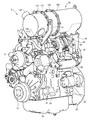
- the tractor 1 is configured to travel forward and backward by driving the rear wheels 4 and the front wheels 3 with a common rail type diesel engine 5 (hereinafter simply referred to as an engine) as a power source mounted on the front portion of the traveling machine body 2.
- a common rail type diesel engine 5 hereinafter simply referred to as an engine
- the engine 5 is covered with a bonnet 6.
- a cabin 7 is installed on the upper surface of the traveling machine body 2.
- a steering seat 8 and a steering handle (round handle) that moves the steering direction of the front wheel 3 to the left and right by steering. 9 are arranged inside the cabin 7.
- a step 10 on which the operator gets on and off is provided at the outer lower portion of the cabin 7.
- a fuel tank 11 that supplies fuel to the engine 5 is provided below the bottom of the cabin 7.
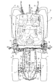
- the traveling machine body 2 includes an engine frame (front frame) 14 having a front bumper (frame connecting member) 12 and a front axle case 13, and left and right machine body frames (rear frame) 15 detachably fixed to the rear part of the engine frame 14. It is comprised by.
- a front axle 16 is rotatably protruded outward from the left and right ends of the front axle case 13.
- the front wheels 3 are attached to the left and right ends of the front axle case 13 via the front axle 16.
- a transmission case 17 is connected to the rear part of the body frame 15 for appropriately changing the rotational power from the engine 5 and transmitting it to the front and rear four wheels 3, 3, 4, 4.
- a tank frame 18 having a rectangular frame plate shape in a bottom view projecting outward in the left and right directions is bolted to the lower surface sides of the left and right body frames 15 and the mission case 17.
- the fuel tank 11 of the embodiment is divided into left and right two parts.
- the left and right fuel tanks 11 are distributed and mounted on the upper surface side of the left and right projecting portions of the tank frame 18.
- the left and right rear axle cases 19 are mounted on the left and right outer surfaces of the mission case 17 so as to protrude outward.
- Left and right rear axle cases 20 are rotatably inserted in the left and right rear axle cases 19.
- the rear wheel 4 is attached to the mission case 17 via the rear axle 20.
- Upper portions of the left and right rear wheels 4 are covered with left and right rear fenders 21.
- a hydraulic lifting mechanism 22 that lifts and lowers a work machine such as a rotary tiller is detachably attached to the rear upper surface of the mission case 17.
- a working machine such as a rotary tiller is connected to the rear portion of the transmission case 17 via a three-point link mechanism including a pair of left and right lower links 23 and a top link 24.
- a PTO shaft 25 for transmitting a PTO driving force to a working machine such as a rotary tiller is provided to project rearward.
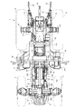
- a flywheel 61 is attached to an engine output shaft 53 that protrudes rearward from the rear side of the engine 5.
- a main shaft 27 projecting rearward from the flywheel 61 and a main transmission input shaft 28 projecting forward from the front side of the transmission case 17 are connected via a power transmission shaft 29 having universal shaft joints at both ends.
- a hydraulic continuously variable transmission, a forward / reverse switching mechanism, a traveling auxiliary transmission gear mechanism, and a differential gear mechanism for rear wheels are arranged in the transmission case 17, a hydraulic continuously variable transmission, a forward / reverse switching mechanism, a traveling auxiliary transmission gear mechanism, and a differential gear mechanism for rear wheels are arranged.
- the rotational power of the engine 5 is transmitted to the main transmission input shaft 28 of the transmission case 17 via the main driving shaft 27 and the power transmission shaft 29, and is appropriately shifted by the hydraulic continuously variable transmission and the traveling auxiliary transmission gear mechanism. Then, the transmission power is transmitted to the left and right rear wheels 4 through the rear wheel differential gear mechanism.
- the front wheel output shaft 30 projecting forward from the lower front portion of the transmission case 17 projects rearward from the front axle case 13 containing a front wheel differential gear mechanism (not shown) via a front wheel drive shaft 31.
- a front wheel transmission shaft (not shown) is connected. Transmission power by the hydraulic continuously variable transmission and the traveling auxiliary transmission gear mechanism in the transmission case 17 is transmitted from the front wheel output shaft 30, the front wheel drive shaft 31, and the front wheel transmission shaft to the front wheel differential gear mechanism in the front axle case 13. Is transmitted to the left and right front wheels 3 via.
- the transmission case 17 includes a front transmission case 112 having a main transmission input shaft 28 and the like, a rear transmission case 113 having a rear axle case 19 and the like, and a front side of the rear transmission case 113 connected to the rear side of the front transmission case 112.
- An intermediate case 114 is provided.
- the rear ends of the left and right machine body frames 15 are connected to the left and right side surfaces of the intermediate case 114 via the left and right upper and lower machine body connecting shafts 115 and 116. That is, the rear end portions of the left and right airframe frames 15 are connected to the left and right side surfaces of the intermediate case 114 by the two upper airframe connecting shaft bodies 115 and the two lower airframe connecting shaft bodies 116.
- the mission case 17 is integrally connected to form the rear part of the traveling machine body 2. Further, the front transmission case 112 or the power transmission shaft 29 is disposed between the left and right body frames 15 to configure the traveling machine body 2 so as to protect the front transmission case 112 and the like.
- left and right front support bases 96 that support the front side of the cabin 7 and left and right rear support bases 97 that support the rear part of the cabin 7 are provided.
- a front support 96 is bolted to the front end of the left and right machine frame 15 and the front bottom of the cabin 7 is supported on the upper surface of the front support 96 via a vibration isolating rubber member 98. is doing.
- a rear support 97 is fastened to the middle of the left and right widths of the upper surface of the left and right rear axle cases 19 extending horizontally in the left-right direction, and the cabin 7 is connected to the upper surface of the rear support 97 via a vibration isolating rubber body 99.
- Anti-vibration support is provided at the rear bottom. Accordingly, the traveling machine body 2 supports the cabin 7 in a vibration-proof manner via the plurality of vibration-proof rubber bodies 98 and 99.
- a rear support 97 is disposed on the upper surface side of the rear axle case 19 and an anti-sway bracket 101 is disposed on the lower surface side of the rear axle case 19 so that the end face of the cross section sandwiches the rear axle case 19 having a substantially rectangular tube shape.
- the rear support 97 and the steady bracket 101 are fastened with bolts 102.
- Both ends of a steady-state rod body 103 with turnbuckles that can be expanded and contracted are connected to an intermediate portion of the lower link 23 that extends in the front-rear direction and the steady-rest bracket 101 to prevent left-right vibration of the lower link 23. is doing.
- the cabin 7 that covers the control seat 8 on the traveling machine body 2 includes a cabin frame 300 that forms a framework.
- the cabin frame 300 includes a pair of left and right front columns 301 positioned in front of the control seat 8, a pair of left and right rear columns 302 positioned behind the control seat 8, and a front beam that connects between the upper ends of the front columns 301.
- a roof body 306 is detachably attached to the upper end side of the cabin frame 301, that is, on a rectangular frame constituted by the front beam member 303, the rear beam member 304, and the left and right side beam members 305.
- the longitudinal ends of the left and right bottom frames 311 extending in the front-rear direction are connected to the lower ends of the front column 301 and the rear column 302.
- the floor plate 40 is stretched on the upper surface side of the left and right bottom frames 311, the dashboard 33 is erected on the front end side of the floor plate 40, and the steering handle 9 is installed on the rear surface side of the dashboard 33 via the steering column 32.
- a brake pedal 35 and the like are disposed on the front upper surface side of the floor board 40, and the control seat 8 is attached to the rear upper surface side of the floor board 40.
- the air conditioner 364 for managing the air conditioning in the cabin 7 is accommodated in the rear part of the roof body 306 attached to the upper end side of the cabin frame 301.
- the air conditioner 364 adjusts the air conditioning (indoor temperature) in the cabin 7 by heating using the cooling water of the engine 5 or cooling using the compressor 211, the condenser 275, and the evaporator driven by the engine. .
- a refrigerant hose 280 connected to the air conditioner 364 is piped to the front lower side along the cabin frame 301.
- the columns 301 and 302 and the beam members 303, 304, and 305 are arranged on the sides of the cabin 7 (cabin frame 300).
- the cabin 7 cabin frame 300.
- a front window glass 321, a rear window glass 322, and left and right side doors 323 made of transparent glass are disposed on the front, rear, left and right side surfaces of the cabin frame 300.
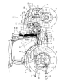
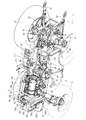
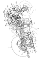
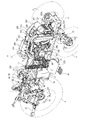
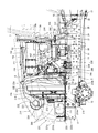
- the diesel engine 5 has a cylinder head 55 mounted on a cylinder block 54 containing an engine output shaft 53 and a piston, and an intake manifold 56 is disposed on the right side surface of the cylinder head 55.
- an exhaust manifold 57 is disposed on the left side of the cylinder head 55. That is, in the engine 5, the intake manifold 56 and the exhaust manifold 57 are distributed and arranged on both side surfaces along the engine output shaft 53.
- a cooling fan 59 is disposed on the front surface of the cylinder block 54 in the diesel engine 5, while a flywheel 61 is disposed on the rear surface of the cylinder block 54. That is, the flywheel 61 and the cooling fan 59 are arranged separately on both side surfaces of the engine 5 that intersect the engine output shaft 53.
- the flywheel 61 is disposed in the flywheel housing 60.
- a flywheel 61 is pivotally supported on the rear end side of the output shaft 53.
- the power of the diesel engine 5 is taken out via the output shaft 53 to the working part of the work vehicle.
- An engine starter 69 is provided in the flywheel housing 60.
- the pinion gear of the starter 69 for starting the engine meshes with the ring gear of the flywheel 61.
- cranking is executed
- An engine leg mounting portion 60 a is provided on the upper surface of the life wheel housing 60.
- a rear engine leg (engine mount) 240 having anti-vibration rubber can be bolted to the engine leg mounting part 60a.
- the diesel engine 5 has an oil pan 62 disposed on the lower surface of the cylinder block 54.
- Lubricating oil in the oil pan 62 is supplied to each lubricating portion of the diesel engine 5 through an oil filter 63 disposed on the right side surface of the cylinder block 54.
- the oil filter 63 is attached to the right side surface of the cylinder block 54 via an oil filter support member 88.
- One side surface (left side surface) of the oil filter support member 88 is connected to a connection port (oil filter mounting position) with the oil passage provided in the cylinder block 54, and the other side surface (right side surface) of the oil filter support member 88 is upper side. Attach the oil filter 63 to the.
- the oil filter 63 has an oil filter support member 88 interposed when the oil filter 63 is attached to the cylinder block 54. Therefore, the oil filter 63 is disposed above the original mounting position in the cylinder block 54, and interferes with the traveling machine body 2 even when the engine 5 is mounted on the traveling machine body 2 having a narrow left and right width. There is nothing. In other words, the oil filter 63 is disposed above the engine frame 14 by the oil filter support member 88. Further, the right engine cover 232 has a shape in which a part of the lower edge is cut out, and the front surface of the oil filter 63 projects outward from the right engine cover 232. Therefore, the oil filter 63 can be easily accessed, and the oil filter 63 can be easily replaced.
- the oil filter support member 88 is provided with an oil passage (not shown) therein, and the lubricating oil sucked from the oil pan 62 by an oil pump (not shown) is supplied from the oil passage (not shown) in the cylinder block 54. Then, the oil filter 63 is supplied. Further, the lubricating oil filtered by the oil filter 63 is returned to the cylinder block 54 and supplied to each lubricating portion of the engine 5. At this time, part of the lubricating oil filtered by the oil filter 63 is supplied from the lubricating oil discharge port 88b to the external component via the lubricating oil supply pipe 89. Since a part of the lubricating oil flow path from the oil filter 63 to the external part is constituted by the oil passage in the oil filter support member 88, the oil filter support member 88 can share a plurality of functions, The number of components can be reduced.
- the diesel engine 5 includes a fuel supply pump 64 for supplying fuel, a cylindrical common rail 66 for pumping fuel to the injector, a fuel filter 67 for removing foreign matter from the fuel from the fuel tank 11, an intake manifold 56, A connected EGR device 75 is provided on the right side surface thereof.
- the fuel in the fuel tank 11 is supplied to the fuel supply pump 64 via the fuel filter 67, and is then pumped from the fuel supply pump 64 to the common rail 66. Accordingly, since the high-pressure fuel is stored in the common rail 66, the high-pressure fuel in the common rail 66 is injected into each cylinder of the engine 5 from each injector by controlling the opening and closing of the fuel injection valve of each injector.
- a cooling water pump 71 for lubricating lubricating water is arranged coaxially with the fan shaft of the cooling fan 59 on the front side (cooling fan 59 side) of the cylinder head 55.
- the cooling water pump 71 is configured to be driven together with the cooling fan 59 by the rotation of the engine output shaft 53.
- the cooling water in the radiator 235 mounted on the work vehicle is supplied to the cooling water pump 71 via a thermostat case 70 provided on the upper part of the cooling water pump 71. Then, when the cooling water pump 71 is driven, cooling water is supplied to a water cooling jacket (not shown) formed in the cylinder head 55 and the cylinder block 54 to cool the diesel engine 5. Cooling water that has contributed to cooling the diesel engine 5 is returned to the radiator 235.
- the cooling water pump 71 faces the cooling fan 59 in the positional relationship, and the cooling air from the cooling fan 59 strikes the cooling water pump 71.
- the cooling water in the radiator 235 is supplied to the cylinder block 54 and the cylinder head 55 by driving the cooling water pump 71 to cool the diesel engine 5.
- the engine leg mounting portions 74 are provided on the left and right side surfaces of the cylinder block 54, respectively.
- a front engine leg (engine mount) 238 having anti-vibration rubber can be bolted to each engine leg mounting portion 74.
- the engine leg mounting portions 74 on the cylinder block 54 side are bolted to the engine frames 14 via the engine legs 238 so that the cylinder blocks 54 are sandwiched between the pair of left and right engine frames 14 in the work vehicle. Thereby, both engine frames 14 of the work vehicle support the diesel engine 5 front side.
- An intake communication pipe 76 to which fresh air (external air) is supplied is connected to the right side inlet of the intake manifold 56, and an intake throttle member 77 is provided on the intake inlet side (upstream side) of the intake communication pipe 76.
- a recirculation exhaust gas pipe 78 to which a part of exhaust gas (EGR gas) of the diesel engine 5 is supplied is connected to an upper surface inlet portion of the intake manifold 56 through an EGR valve member 79.
- the intake outlet side (downstream side) of the intake communication pipe 76 and the connection part (rear part) with the EGR valve member 79 are configured as a main body case of the EGR device (exhaust gas recirculation device) 75. Yes.
- the intake intake side of the intake manifold 56 constitutes an EGR main body case.
- the EGR device (exhaust gas recirculation device) 75 is mainly located on the right side of the diesel engine 5, specifically, on the right side of the cylinder head 55, and a part of the exhaust gas (EGR gas) of the diesel engine 5 and new The air is mixed and supplied to the intake manifold 56.
- the EGR device (exhaust gas recirculation device) 75 includes an EGR main body case constituted by a part of the intake manifold 56, an intake communication pipe 76 communicating with the intake manifold 56, and an intake throttle member 77 provided in the intake communication pipe 76.
- the recirculation exhaust gas pipe 78 connected to the exhaust manifold 57 via the EGR cooler 80 and the EGR valve member 79 for communicating the intake manifold 56 with the recirculation exhaust gas pipe 80 are provided.
- the engine 5 connects the EGR cooler 80 and the EGR device 75 that are arranged on both side surfaces by a recirculation exhaust gas pipe 78 that bypasses the rear surface of the engine 5 (the flywheel 61 side) as a reflux line.
- An intake throttle member 77 is connected to the intake intake side of the intake manifold 56 through an intake communication pipe 76.
- the outlet side of the recirculated exhaust gas pipe 78 is also connected to the intake intake side of the intake manifold 56 via an EGR valve member 79.
- the inlet side of the recirculation exhaust gas pipe 78 is connected to the exhaust manifold 57 via the EGR cooler 80.
- fresh air is supplied to the intake intake side of the intake manifold 56 via the intake communication pipe 76 and the intake throttle member 77, while EGR gas is supplied from the exhaust manifold 57 to the intake intake side of the intake manifold 56.
- Fresh air from the outside and EGR gas from the exhaust manifold 57 are mixed on the intake intake side of the intake manifold 56.
- the diesel engine 5 includes a continuous regeneration type exhaust gas purification device (DPF) 52.
- the exhaust gas purification device 52 is provided with an exhaust gas inlet pipe 161 on the outer peripheral surface of the case on one end side (rear side) in the longitudinal direction, and the exhaust gas inlet pipe 161 is connected to the exhaust gas of the turbine case 82 in the turbocharger 81.
- the exhaust side communicates with the exhaust side through an exhaust communication pipe 84.
- the exhaust gas inlet pipe 161 is opened toward the lower left side, while the exhaust gas outlet pipe 162 is opened upward on the right side.
- the exhaust gas purification device 52 is connected to an exhaust communication pipe 84 that communicates with the turbocharger 81, and the exhaust communication pipe 84 is bolted to the exhaust manifold 204 at the lower end side thereof so that the exhaust gas is exhausted. It is configured as a support (DPF support) for the purification device 52.
- the exhaust communication pipe 85 is fastened to the exhaust discharge side of the turbine case 82 in the turbocharger 81 by a bolt, and the exhaust discharge side is fastened to the exhaust gas inlet 161 of the exhaust gas purification device 52. Therefore, the exhaust manifold 57 and the exhaust gas purification device 52 communicate with each other via the turbine case 82 and the exhaust communication pipe 84 in the turbocharger 81.
- the engine 5 includes an outlet side bracket body 176 and an inlet side bracket body 177 as a housing support body that supports and fixes the exhaust gas purifying device 52.
- the outlet side bracket body 176 and the inlet side bracket body 177 are erected on the front side and the rear side that intersect the engine output shaft 53 in the cylinder head 55 of the engine 5.
- the inlet side bracket body 177 is located on the rear surface side of the engine 5 and supports the exhaust intake side of the exhaust gas purification device 52 together with the exhaust communication pipe 84.
- the outlet side bracket body 176 is located on the front side of the engine 5 and supports the exhaust discharge side of the exhaust gas purification device 52.
- the inlet side bracket body 176 is located on the rear side of the cylinder head 55 (above the flywheel housing 60).
- the inlet side bracket body 176 has a lower end side of the fixed bracket (first bracket) 178 fastened to the rear surface of the cylinder head 5 with a bolt.
- a relay bracket 179 is bolted to the upper end side of the fixed bracket 178.
- the proximal end side of the extension bracket (third bracket) 180 is bolted to the middle portion of the relay bracket (second bracket) 179, and the distal end side of the extension bracket 180 is the inlet of the gas purification housing 168 via the bolt and nut. Fastened to the side lid (upstream lid) 169.
- the outlet side bracket body 177 is located on the front side of the cylinder head 55 (on the cooling fan 59 side).
- the outlet side bracket body 177 of the embodiment is configured to be divided into an outlet side first bracket (fourth bracket) 181 and an outlet side second bracket (fifth bracket) 182.
- the outlet-side first bracket 181 is formed of a substantially L-shaped member that extends upward from the right side of the cylinder head 55 and is bent leftward above the cylinder head 55.
- the outlet-side second bracket 182 is configured by a substantially L-shaped member that extends upward from the left side of the cylinder head 55 and is bent rightward above the cylinder head 55. Therefore, the outlet side bracket body 177 has a substantially portal shape on the front surface side of the cylinder head 55 and is fixed so as to straddle the cylinder head 55 at the rear position of the thermostat case 70.
- the exhaust gas purifying device 52 of the embodiment is disposed above the diesel engine 4 via the exhaust communication pipe 84, the inlet side bracket body 176, and the outlet side bracket body 177, which are housing supports.
- the cylinder head 55, the intake manifold 56 and the exhaust manifold 57 of the engine 1 are detachably connected.
- the inlet side bracket body 176 and the exhaust communication pipe 84 on the upstream side (exhaust intake side) in the exhaust gas movement direction are distributed to the cylinder head 55 and the exhaust manifold 57, and downstream in the exhaust gas movement direction (exhaust exhaust side).
- the fixing bracket 178 is provided with a side part connecting part 178c having a bolt hole on the right side surface of the upper end portion, and for fixing an external part such as the exhaust pipe 227 to the side part connecting part 178c.
- the component fixing bracket (exhaust pipe fixing bracket) 210 is bolted.
- the base end portion of the outlet side first bracket 181 includes a base end side component connecting portion 181b for fixing a component fixing bracket (compressor fixing bracket) 212 for fixing external components such as the air conditioning compressor 211.
- a part fixing bracket (hot water pipe fixing bracket) 208 for fixing external parts such as the hot water pipes 203 and 204 for air conditioning, for example, is fixed on the upper surface of the bent part (midway part) of the outlet side first bracket 181.
- a component connecting portion 181d is provided.
- a rear part connecting portion 182d for fixing a component fixing tool (shielding plate fixing bracket) 207 for supporting the upstream relay pipe 223 and the shielding plate 206 is provided at a bent portion (midway portion) of the outlet side second bracket 182. I have.
- the bonnet 6 of the tractor 1 is formed in a U-shaped cross section downward. Then, the left and right corners of the bonnet 6 are chamfered so as to be inclined obliquely downward to the left and right outside in a front view, so that the front view of the operator seated on the control seat 8, particularly the left and right sides of the bonnet 6, Good visibility.
- the exhaust gas purification device (DPF) 52 and the exhaust communication pipe 84 are opposed to the left inner wall surface of the bonnet 6, while the intake communication pipe 76 is opposed to the right inner wall surface of the bonnet 6. Further, the exhaust communication pipe 84 is disposed at a position facing the left engine cover 232, while the intake communication pipe 76 is disposed at a position facing the right engine cover 232.
- the intake communication pipe 76 having a hollow portion for supplying fresh air to the intake manifold 56 is inclined upward toward the cylinder head 55 and extends upward from the intake manifold 56. That is, in the intake communication pipe 76, the fresh air intake port on the upper end side is offset toward the output shaft 53 (engine 5 center position) of the engine 5 with respect to the fresh air discharge port on the lower end side.
- the intake communication pipe 76 is arranged along the shape narrowed upward in the bonnet 6, and the intake throttle member 77 is disposed between the upper part of the engine 5 and the inner surface of the bonnet 6 than the intake communication pipe 76. Can be placed closer to the center position.
- downstream relay pipe 225 that allows the fresh air discharge side of the intercooler 224 and the intake throttle member 77 to communicate with each other can be designed to be short, and can be compactly accommodated in the hood 6 that has a narrower left and right width.
- the exhaust communication pipe 84 having a hollow portion for supplying the exhaust gas from the exhaust manifold 57 to the exhaust gas purification device 52 is structured to be inclined upward toward the cylinder head 55, and the exhaust gas of the exhaust gas purification device 52.
- the exhaust gas purification device 52 is supported by being connected to the inlet pipe 161. That is, the exhaust communication pipe 84 is connected to the lower end side connection support portion 84a connected to the lower end side exhaust manifold 57, and the upper end side exhaust gas discharge port is connected to the output shaft 53 (engine 5 center position) of the engine 5. It is offset closer. Further, the exhaust gas purification device 52 is configured to incline the exhaust gas inlet pipe 161 toward the lower side (inlet flange body side) toward the outer side of the engine 5 (bonnet 6 inner wall side).
- the exhaust gas purification device 52 and the exhaust communication pipe 84 are arranged along a shape narrowed upward in the bonnet 6, and the exhaust gas purification device 52 is disposed between the upper portion of the engine 5 and the inner surface of the bonnet 6. It can be supported near the center position. Therefore, the exhaust gas purifying device 52 can be accommodated in a compact manner in the bonnet 6 whose lateral width becomes narrower upward.
- the exhaust gas purifying device 52 which is a heavy object, can be supported close to the center of gravity of the engine 5, and an increase in vibration, noise, etc. of the engine 5 due to the exhaust gas purifying device 52 being mounted can be suppressed. Further, the influence on the shape of the hood 6 due to the exhaust gas purification device 52 being assembled to the engine 5 can be reduced, and the shape of the hood 6 need not be complicated.
- a flywheel housing 60 that covers a flywheel 61 disposed on an end surface that intersects the core line of the engine output shaft 53 is configured to have a width W1 narrower than a height H1.
- the engine 5 can be mounted without causing the flywheel housing 60 to interfere with the traveling machine body 2 having a narrow left and right width.
- the width between the left and right machine engine frames 15 is wider than the width between the left and right engine frames 14.
- the flywheel housing 61 is disposed rearward, and the main transmission input shaft 28 of the transmission case 17 connected to the body frame 15 and the flywheel 61 are connected. Accordingly, the flywheel housing 61 having the widest left-right width in the engine 5 can be sufficiently disposed between the body frames 15 and the flywheel housing 61 can be prevented from colliding with the traveling body 2 having a different vibration system. Damage can be prevented.
- the flywheel housing 61 has an outer shape in which a left and right sides of a circle are cut out and at the same time an pedestal engine leg mounting portion 60a is protruded on the upper portion, and the upper engine leg mounting portion 60a is interposed via a rear engine leg body 240. And connected to the traveling machine body 2.
- the flywheel housing 61 not only can be mounted on the traveling machine body 2 having a narrow width, but also forms a pedestal-shaped engine leg mounting portion 60 a that can be connected to the traveling machine body 2. Therefore, the rigidity by the support structure of the engine 5 can be compensated by connecting to the traveling machine body 2 by the flywheel housing 61 having high rigidity.
- a portal-type engine support frame 237 is installed above the support beam frame 236 that bridges the pair of left and right aircraft frames 15, and the flywheel housing 61 and the engine support beam frame 237 are arranged side by side. Arrange. Then, the rear surface of the engine leg 238 is connected to the upper surface of the engine support frame 237 via the anti-vibration rubber 239 while being connected to the upper surface of the engine leg mounting portion 60a on the flywheel housing 61 in front of the engine leg 238.
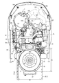
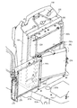
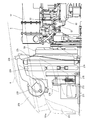
- FIG. 16 and 17 the bonnet 6 forms a front grill 231 on the lower side of the front portion and covers the front of the engine room.
- An engine cover 232 formed of a perforated plate is disposed on the lower left and right sides of the bonnet 6 to cover the left and right sides of the engine room. That is, the hood 6 and the engine cover 232 cover the front, upper, and left and right sides of the diesel engine 5.
- the bonnet 6 includes a front grille 231 at the center of the front surface, and the ceiling portion on the upper side of the bonnet 6 has a shape inclined obliquely upward from the front to the rear. ing.
- the front grill 231 includes a pair of left and right dustproof nets 231b fixed by a central frame 231a.
- the bonnet 6 has a wider space at the lower rear side of the ceiling, and a large space for accommodating the exhaust gas purification device 52 can be formed in the engine room inside the bonnet 6.
- the bonnet 6 has an opening hole 268 in front of each of the left and right side surfaces, and takes in cooling air from both the left and right sides of the bonnet 6 through a pair of left and right opening holes 268.
- the bonnet 6 is also provided with a pair of left and right net-like opening holes 270 in front of the ceiling, and the cooling air is taken in from the upper front side of the bonnet 6 through the pair of left and right opening holes 270.
- the opening holes 268 and 270 are covered with a net-like dustproof net.
- the paired left and right engine frames (front frames) 14 have their front end side inner surfaces connected to the left and right outer surfaces of the frame connecting member 12.
- the frame connecting member 12 is made of a rectangular metal casting, and the diesel engine 5 is supported on the engine frame 14 installed by the frame connecting member 12.
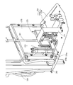
- a frame bottom plate 233 is installed on the upper edges of the left and right engine frames 14 and the upper surface of the front bumper 12 so as to cover the upper front side of the engine frame 14.
- An under cover 296 that covers the lower front side of the engine 5 is disposed at the rear end of the frame bottom plate 233.
- the under cover 296 has a front end connected to the frame bottom plate 233 and a rear left and right side edge connected to the left and right engine frames 14.
- the under cover 296 includes a front part that extends from the rear end of the frame bottom plate 233 toward the lower end of the engine frame 14, and a rear part that extends forward and below the engine 5.
- the lower surface of the frame bottom plate 233 is connected to the side surfaces of the left and right engine frames 14 via connecting brackets 233a and 233b arranged on the front and rear sides. Further, the frame bottom plate 233 is constituted by a front bottom plate 233x and a rear bottom plate 233y which are divided into front and rear parts. The left and right edge sides of the lower surface of the front bottom plate 233x are connected to the front of the other end of the connection bracket 233a that connects one end to the side of the pair of left and right engine frames 14, and the front side of the front bottom plate 233x is fastened to the frame connecting member 12. Has been.
- the rear bottom plate 233y connects the left and right edge sides of the front lower surface with the other end rear of the pair of left and right connection brackets 233a, and connects the left and right edge sides of the front lower surface to the other ends of the pair of left and right connection brackets 233b.
- the frame bottom plate 233 is provided with an opening hole 233z in the left and right central region.
- the opening hole 233z is provided in the front bottom plate 233x of the frame bottom plate 233 and is covered with a net-like dustproof net. That is, each of the bonnet 6 and the frame bottom plate 233 has openings 231b, 233a, 268, 270 at positions ahead of the cooling fan 59 of the engine 5, and the bonnet 6 and the frame bottom plate are driven by the cooling fan 59. Cooling air is taken into the engine room in the bonnet 5 from the openings 231 b, 233 z, 268, and 270 of the 233.
- the opening area can be made larger than the air flow rate through which the cooling fan 59 passes in a limited configuration in front of the cooling fan 59.
- the flow velocity of the cooling air passing through the cooling fan 59 can be suppressed, the cooling air in the engine room can be optimally controlled, and not only the back flow in the engine room is prevented, but also the cooling air is effective on the engine 5 side. Can be guided.
- the opening 233z of the frame bottom plate 233 into a net shape, it is possible to prevent dust from entering the engine room, and it is possible to drop the dust by its own weight after the engine 5 is stopped.
- the opening 233z of the frame bottom plate 233 is disposed at a position above the frame connecting member 12. Since the frame connecting member 12 of the traveling machine body 2 is disposed below the opening 233z of the frame bottom plate 233, when the outside air flows into the engine room through the opening 233z, the frame connecting member 12 prevents dust and mud from entering. Can do. Moreover, the support structure of the engine 5 can be strengthened by fixing the engine frame 14 that supports the engine 5 with the frame connecting member 12 that is a metal casting.
- the installation direction of the engine ECU 271 can be aligned with the cooling air flowing in the front-rear direction in the engine room by the cooling fan 59.
- engine ECU271 can reduce the shielding area with respect to the flow of cooling air, the fall of the cooling air flow rate to engine 5 can be controlled, and the inside of an engine room can be maintained at a proper temperature.
- the frame bottom plate 233x has a harness conduction hole 233w in the vicinity of the standing position of the engine ECU 271 and at a position behind the opening 233z.
- a harness (not shown) connected to the engine ECU 271 is guided to the bottom side of the traveling machine body 2 through the harness conduction hole 233w, and is connected to the rear engine 5, the battery 272, and the like.
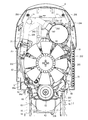
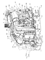
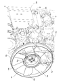
- a radiator 235 having a fan shroud 234 attached to the back side is erected on the rear bottom plate 233y of the frame bottom plate 233 so as to be positioned on the front side of the engine 5.
- the fan shroud 234 surrounds the outer peripheral side of the cooling fan 59 and allows the radiator 235 and the cooling fan 59 to communicate with each other.
- the radiator 235 is supported inside a rectangular radiator frame 260 fixed to the frame bottom plate 233 in an upright state.
- the radiator frame 260 is provided with a dust-proof net 260a on the front surface, so that intrusion of dust and the like into the frame-shaped radiator frame 260 is prevented.
- the radiator frame 260 is fixed on the frame bottom plate 233 so as to surround the inner radiator 235 and is also connected to the fan shroud 234.
- a frame frame 226 is erected on the rear bottom plate 233 y of the frame bottom plate 233 on the front side of the radiator 235.
- the frame frame 226 includes an air cleaner support frame 261 that supports the air cleaner 221.
- the air cleaner support frame 261 is a bent rod-shaped frame, and one end is connected to the rear bottom plate 233y and the other end is connected to the radiator frame 260.
- An air cleaner 221 is fixed above the air cleaner support frame 261, and a fuel cooler 273 for cooling the fuel is fixed to the air cleaner support frame 261 at a position below the air cleaner 221.
- the frame frame 226 includes a portal frame 262 that is bent into a portal shape and fixed at both ends on the frame bottom plate 233y.
- the portal frame 262 is erected between the radiator frame 260 and the air cleaner support frame 261 with both left and right ends (lower ends) coupled to the frame bottom plate 233y.
- the left and right central portions of the upper frame of the portal frame 262 are connected to the upper and lower middle portions of the air cleaner support frame 261.
- the air cleaner support frame 261 supports the air cleaner 221 above the connection portion with the portal frame 262 and supports the fuel cooler 273 below the connection portion with the portal frame 262.
- the gate-type frame 262 supports the oil cooler 274 for cooling the lubricating oil on the rear side (the radiator 235 side), and supports the condenser 275 for cooling the refrigerant on the front side (the fuel cooler 273 side).
- the intercooler 224 is vertically clamped by the intercooler connection bracket 263 fixed to the upper end side of the air cleaner support frame 261 and the upper frame of the portal frame 262, and the intercooler 224 is supported above the oil cooler 274. is doing.
- a dustproof net 263a is sandwiched and supported in front of the intercooler 224 by an upper frame of the portal frame 262 and an intercooler connection bracket 263.
- the capacitor 275 is constituted by a case integrated type, and a receiver dryer 276 for separating the refrigerant into a gas and liquid is connected and fixed to the side of the case, and a dustproof net 27a is provided on the front of the case.
- the air cleaner support frame 261 erected from the bottom plate frame 233 is bent obliquely rearward above the condenser 275 and further bent rearward above the intercooler 224. Accordingly, the air cleaner 221 is supported by the air cleaner support frame 261 so as to be positioned above the capacitor 275 at a position partially overlapping with the capacitor 275 in the front-rear direction.
- a plurality of heat exchangers including the intercooler 224 are arranged on the front surface of the radiator 235 so that the pressure loss of the offset portion with the cooling fan 59 is reduced. .
- the flow velocity distribution of the cooling air flowing in the fan shroud 234 is leveled, and the generation of the differential pressure in the fan shroud 234 can be suppressed. Therefore, the backflow of the cooling air in the radiator 235 can be prevented, and the cooling efficiency in the radiator 235 can be increased.
- the intercooler 224 is disposed on the front upper side of the radiator 235
- the oil cooler 274 for cooling the lubricating oil is disposed on the lower front side of the radiator 235
- the condenser 275 is disposed on the front side of the oil cooler 274.
- the air cleaner 221 is fixed at a position separated from the intercooler 224 in front of the intercooler 224.
- a space can be provided above the radiator 235 so that the cooling air can easily flow into the radiator 235.
- the flow velocity distribution of the cooling air in the engine room under the hood 6 can be leveled in the height direction, and the backflow of the cooling air can be suppressed.
- the air cleaner 221 and the capacitor 275 are arranged in front of the radiator 235 so that the capacitor 275 can be pulled out in the left-right direction.
- the rail 262 a is provided on the front side of the upper frame of the portal frame 262, while the rail 262 b is installed at a position directly below the rail 262 a of the frame bottom plate 233. Then, the upper and lower edges of the capacitor 275 are engaged with the upper and lower rails 262a and 262b, so that the capacitor 275 is sandwiched between the portal frame 262 and the rear bottom plate 233y so as to be slidable in the left-right direction.
- the condenser 275 is integrally formed with a receiver dryer 276 in which refrigerant hoses 277 and 278 connected to the air conditioning compressor 211 and the air conditioner 364 are coupled.
- the refrigerant hoses 277 and 278 are gripped so as to be hooked by the fan shroud 235 and the intercooler connection bracket 263.
- the capacitor 275 can be pulled out only by removing the hooks of the refrigerant hoses 277 and 278, and there is no need to remove the refrigerant hoses 277 and 278 from the receiver dryer 276. In this way, in the engine room, the space behind the air cleaner 221 is used to pull out the capacitor 275, thereby making it easy to access the space behind the capacitor 275. Therefore, the complexity of maintenance work such as dust removal work behind the capacitor 275 can be eliminated.
- an intercooler 224 and an oil cooler 274 are arranged one above the other, and the oil cooler 274 is rotated around a vertical axis in a portal frame (fixed frame) 262 that fixes the upper intercooler 224. It is fixed so that it can move. That is, a shaft support member 262 c is provided on either one of the left and right frames of the portal frame 262, one of the left and right side surfaces of the oil cooler 274 is pivotally supported around the vertical axis, and the oil cooler 274 is attached to the portal frame 262. It can be opened and closed.
- the condenser 275 is pulled out to the right together with the receiver dryer 276 installed on the right side surface, so that the oil cooler 274 is pivotally supported on the right frame of the portal frame 262. Since the oil cooler 274 is installed behind the pullable condenser 275 so as to be rotatable around the vertical axis, the operator can easily access the lower part of the front surface of the radiator 235 where dust tends to accumulate due to the flow of cooling air, and the maintenance work is complicated. Can be eliminated.
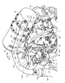
- the upstream relay pipe 223 and the downstream relay pipe 225 are arranged separately on both sides of the engine 5 and are installed on the frame frame 226 in front of the engine 5. It extends toward the front upper side of the engine 5 so as to be connected to the intercooler 224. Further, the air cleaner 221 is arranged on the upper front side of the frame frame 226, and an air supply pipe 222 connected to the air cleaner 221 extends over the frame frame 226 and extends behind the left side of the engine 5. The fresh air intake side of the intake communication pipe 76 of the engine 5 communicates with the downstream relay pipe 225 via the intake throttle member 77. Further, the turbine supercharger 81 of the engine 5 has the fresh air intake side of the compressor case 83 in communication with the air supply pipe 222, while the fresh air discharge side of the compressor case 83 is in communication with the downstream relay pipe 225. Yes.
- fresh air (external air) sucked into the air cleaner 221 is removed by the air cleaner 221 and purified, and then sucked into the compressor case 83 of the turbocharger 81 through the air supply pipe 222.
- the pressurized fresh air compressed in the compressor case 83 of the turbocharger 81 is supplied to the EGR main body case of the EGR device 75 via the relay pipes 223 and 225 and the intercooler 224.
- part of the exhaust gas (EGR gas) from the exhaust manifold 57 is cooled by the EGR cooler 80 and then supplied to the EGR main body case of the EGR device 75 via the recirculation exhaust gas pipe 78.
- the air supply pipe 222, the upstream relay pipe 223, and the downstream relay pipe 225 are arranged in the left and right directions, so that the turbocharger 81 and the intake manifold 56 are left and right.
- the piping can be efficiently performed with respect to the engine 5 that is distributed and arranged. Therefore, by arranging the pipes 222, 223, and 225 for the air flow path to the outside of the engine 5 without difficulty, the heating based on the exhaust heat of the engine 5 and the exhaust gas purification device 52 is suppressed, and the inside of the pipe is The thermal influence on the passing air can be reduced.
- the intercooler 224 arranged in front of the engine room can be arranged by distributing the fresh air outlet side and the fresh air inlet side to the left and right. Accordingly, not only can the upstream relay pipe 223 and the downstream relay pipe 225 communicated with the engine 5 be shortened, but the intercooler 224 can be accommodated compactly in front of the engine room.
- the front end sides of the left and right airframe frames 15 are connected to the rear end sides of the left and right engine frames 14 via spacers 297, and the left and right airframe frames 15 are connected to each other. It arrange
- the connection surface (outer surface) of the support beam frame 236 with the body frame 15 is the same surface as the connection surface (outer surface) of the spacer 297 with the body frame 15.
- the support beam frame 236 is bolted to the left and right airframe frames 15 to mount the left and right airframe frames 15, and the engine support frame 237 is mounted on the upper surface thereof.
- the engine support frame 237 has a shape that surrounds the flywheel 61 of the diesel engine 5 together with the support beam frame 236 by fastening the lower end surface of the engine support frame 237 with the upper surface of the support beam frame 236.
- the diesel engine 5 includes an engine support bracket 298 provided at a middle portion of the pair of left and right engine frames 14 with an engine leg mounting portion 74 provided on the lower side of the left and right side surfaces thereof via an engine leg 238 having a vibration isolation rubber 239. It is connected.
- an engine leg mounting portion 60 a provided on the rear flywheel housing 60 is connected to the upper surface of the engine support frame 237 via an engine leg (engine mount) 240 having a vibration isolation rubber 241. .
- the engine leg 238 is bolted to the upper part of the engine support bracket 298 connected to the outside of the middle part of the pair of left and right engine frames 14 with the anti-vibration rubber 239 on the lower side.
- the diesel engine 5 is sandwiched between the engine frames 14 by a pair of left and right engine legs 238 to support the front side of the diesel engine 5.
- the rear surface of the diesel engine 5 is connected to the front end sides of the pair of left and right body frames 15 via the support beam frame 236, the engine support frame 237, and the engine legs 240, and the diesel engine 5 is rearward at the front end of the body frame 15 The side is supported.
- the diesel engine 5 is supported on the traveling machine body 2 by the left and right front vibration isolation rubber 239 and the left and right rear vibration isolation rubber 241.
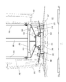
- a pair of left and right support frames 242 and 243 are erected on the upper surface of the engine support frame 237 so as to sandwich the engine leg 240 from the left and right.
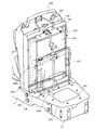
- a bonnet shield plate (shield plate) 244 covering the rear of the bonnet 6 is connected to the pair of left and right support frames 242 and 243 so that the lower edge thereof is separated from the upper surface of the engine leg 240.
- the beam frame 248 is installed over the fan shroud 234 and the bonnet shield plate 244, respectively. Since the fan shroud 234 and the bonnet shield plate 244 that are stably supported by the traveling machine body 2 are installed by being connected by a pair of beam frames 248, these members are integrated to form a robust engine room frame body as a whole. it can.
- the left and right sides of the bonnet shield plate 244 are bent to cover the left and right rear sides of the engine room, while a space is formed between the front surface of the cabin 7 and the noise generated from the engine 5 in the engine room is generated by the cabin 7 ( Propagation to the control seat 8) can be prevented. Further, since the bonnet shield plate 244 has a shape in which both the left and right sides are inclined forward in a plan view, the left and right regions of the space surrounded by the engine room and the cabin 7 under the bonnet 6 are widened. Therefore, as shown in FIG.
- a plurality of refrigerant hoses 277 and 279 on the engine room side connected to the receiver dryer 276 and the air conditioning compressor compressor 211 are connected to the air conditioner 364 of the cabin 7.
- the connection work behind the bonnet shield plate 244 is facilitated.
- the bonnet shield plate 244 includes a rear shield surface (first shield surface) 245 that has a front surface fixed to a pair of left and right column frames 242 and 243 and extends substantially parallel to the front windshield 321 front surface of the cabin 7, and the rear shield surface 245. It is composed of a pair of left and right side shield surfaces (second and third shield surfaces) 246 and 247 inclined forward from the left and right edges. Further, the left and right side shield surfaces 246 and 247 are connected to the middle portions of the support frames 242 and 243 and are supported more firmly.
- first shield surface first shield surface
- second and third shield surfaces second and third shield surfaces
- the bonnet shield plate 244 is disposed at a position separated from the front surface of the windshield 321 by the support frames 242 and 243.
- the left and right side shield surfaces 246 and 247 are inclined so that the left and right edges of the bonnet shield plate 244 are further separated from the front windshield 321 forward, and the cabin 7 is located at the left and right positions behind the bonnet shield plate 244. And can expand the space.
- a bonnet shield plate 244 is disposed on the back side of the bonnet 6 to cover at least the back side of the exhaust gas purification device 52 and the exhaust pipe 227.
- the bonnet shield plate 244 covers at least the back surface of the diesel engine 5 by having a shape projecting left and right from the pair of left and right column frames 242 and 243.
- region of the bonnet shield board 244 right side is open
- hood shield plate 244 By covering the back of the hood 6 with the hood shield plate 244, heat in the engine room under the hood 6 is shielded by the hood shield plate 244, and the cabin 7 side is heated by exhaust heat from the engine room. Can be prevented. Therefore, the operator in the cabin 7 can comfortably operate without being affected by the exhaust heat of the diesel engine 5 and the exhaust gas purification device 52.
- the bonnet shield plate 244 By disposing the bonnet shield plate 244 away from the front surface of the cabin 7, a heat insulating layer is formed between the cabin 7 disposed behind the bonnet 6 and the bonnet shield plate 244.
- a pair of left and right support frames 242 and 243 are connected to a central region (rear shield surface 245) sandwiched between bent portions of the bonnet shield plate 244, and the support frames 242, 243 and A fan shroud 235 is installed on a beam frame 248. Since the fan shroud 235 and the support frames 242 and 243 that are stably supported by the traveling machine body 2 are erected and connected by the beam frame 248, these members are integrated to form a robust engine room frame body as a whole. .
- the bonnet support bracket 255 is installed on the upper end side of the support frames 242 and 243.
- the bonnet support bracket 255 is connected to the hinge member 253 provided at the rear part of the bonnet 6 so that the rear part of the bonnet 6 is pivotally supported on the upper ends of the support frames 242 and 243.
- the bonnet support bracket 255 has a shape in which both right and left edges are bent, and is fixed to the front sides of the support frames 242 and 243.
- the bonnet support bracket 255 is configured in a U shape (U shape) in which both left and right edges are bent rearward, and both ends are connected to the column frames 242 and 243 and the front surface of the beam frame 248 is connected to the bonnet support bracket 255. Connect to the rear end. That is, the beam frame 248 is connected to the support frames 242 and 243 via the bonnet support bracket 255.
- the beam frame 248 is extended in the front-rear direction so that the right edge of the beam frame 248 is located on the right side of the center position of the bonnet 6.
- the exhaust gas purification device 52 is disposed along the beam frame 248 so that the exhaust gas purification device 52 is positioned between the beam frame 248 and the inner side surface of the bonnet 6 above the engine 5. Since the exhaust gas purification device 52 is positioned between the beam frame 248 and the inner side surface of the bonnet 6, the space around the exhaust gas purification device 52 is widened, and the complexity of component assembly and maintenance above the engine 6 can be eliminated.
- a heat shield 250 is provided above the engine 5 so as to cover the rear from the middle of the beam frame 248 under the hood 6.
- Crosspiece frames 251 and 252 are extended on both the left and right sides in the middle part and the rear end of the beam frame 248, respectively. That is, the front crosspiece frame 251 is fixed on the upper halfway part of the beam frame 248 and extends to the left and right of the beam frame 248.
- a rear crosspiece frame 252 is fixed on the upper rear end of the beam frame 248 and extends to the left and right of the beam frame 248. Then, both front and rear edges of the heat shield plate 250 are fixed to a pair of front and rear crosspiece frames 251 and 252.
- the heat shield plate 250 is disposed so as to cover the upper part of the exhaust gas purification device 52 and the exhaust pipe 227 on the upper side of the engine 5. By disposing the heat shield plate 250 between the exhaust gas purifying device 52 and the exhaust pipe 227 and the bonnet 6, it is possible to prevent the bonnet 6 from being heated by exhaust heat from the engine room.
- the exhaust gas purifying device 52 mounted on the upper part of the engine 5 is positioned behind the bonnet 6, and a heat shield plate 250 is disposed between the bonnet 6 and the exhaust gas purifying device 52.
- a heat shield plate 250 is disposed between the bonnet 6 and the exhaust gas purifying device 52.
- a hood shield plate 244 that is disposed on the back side of the bonnet 6 and covers at least the exhaust gas purification device 52 from the back side is provided. Since the heat in the engine room under the hood 6 is shielded by the hood shield plate 244 together with the heat shield plate 250, the cabin 7 can be prevented from being heated by exhaust heat from the engine room. Further, by providing a gap between the bonnet shield plate 244 and the heat shield plate 250, it is difficult to trap hot air in the engine room below the bonnet 6, and heat damage to the exhaust gas purifying device 52 itself, the bonnet 6 and the like is prevented. Generation can be suppressed.
- Extensible gas springs (bonnet dampers) 256 and 256 are disposed on the left and right sides of the heat shield plate 250 below the bonnet 6.
- One end (rear end) of each of the left and right gas springs 256, 256 is pivotally attached to the engine room frame body, and the other end (front end) of each of the gas springs 256, 256 is pivotally attached to the upper inner surface of the bonnet 6. is doing.
- the extension frame 249 has a shape extending left and right with the rear end of the beam frame 248 as the center, and is connected to the left and right ends of the rear frame 252.
- the bonnet 6 is held in the open position by the thrust action of the gas spring 256. Therefore, by lifting the front part of the bonnet 6 and opening the bonnet 6 with the upper end position of the bonnet shield plate 244 as an axis fulcrum, the bonnet 6 can be held open by the gas spring 256, so that the diesel engine 5 Maintenance work can be performed.
- the left engine cover frame 257 has a shape that is inclined upward from the front end toward the rear end.
- the left engine cover frame 257 has a rear end coupled to the left edge of the left side shield surface 246 of the bonnet shield plate 244 and a front end coupled to a coupling bracket 259 connected to the side of the left engine frame 14.
- the connection bracket 259 is fixed to the engine frame 14 at a position between the frame bottom plate 233 and the front engine leg 238.
- the left engine cover 232 is connected to the front and rear end portions and the middle portion of the left engine cover frame, and is connected to the left side surface of the engine support frame 237 and is fixed to the lower side of the left side surface of the bonnet 6.
- the right engine cover frame 258 has a front end connected to a connecting bracket 259 connected to the side of the left engine frame 14, and has a shape that is inclined upward and then bent downward.
- the right engine cover frame 258 has a rear end at the same height as the front end, and both ends of the right engine cover frame 258 are connected to a lower plate 258 a fixed to the engine cover frame 258.
- the engine cover frame 259 connects one end of the upper plate 258b to the bent portion.
- a porous shielding plate 205 that covers the left side surface of the engine 5 is disposed below the exhaust gas purification device (DPF) 52. Since the shielding plate 205 is configured to cover the exhaust manifold 57, the turbocharger 81, and the exhaust communication pipe 84, the high heat source component in the engine 5 is covered with the shielding plate 205. Therefore, the exhaust gas supplied to the DPF 52 can be maintained at a high temperature, and a decrease in the regeneration capability of the DPF 52 can be prevented.
- the shielding plate 205 is made porous, and is disposed so as to face the porous left engine cover 232, so that a part of the air heated by the engine 5 can be passed through the shielding plate 205 and the engine cover 232. Heat can be exhausted to the outside, and heat retention on the left side of the engine 5 that becomes relatively high can be prevented.
- the shield plate 205 is bolted to the exhaust gas intake port side of the exhaust communication pipe 84 (on the connection portion side with the turbine case 82 of the turbocharger 81), and is connected to the second outlet side via the shield plate fixing bracket 207. It is connected to the rear part connecting portion 182 d of the bracket 182 and supported by the engine 5.
- the shielding plate fixing bracket 207 is also connected to an upstream relay pipe 223 that communicates the fresh air intake port of the intercooler 224 and the compressor case 83 of the turbocharger 81, and the upstream relay pipe 223 is also connected to the engine 5. Is supported by the second bracket 182 on the outlet side.
- a heat shield member 206 connected to one side of the engine 5 is provided below the exhaust manifold 57, and an engine starter 69 is provided below the heat shield plate 206. It is arranged.
- the heat shield member 206 connected to the left side surface of the cylinder block 54 is erected toward the engine cover 232 at a position between the engine starter 69 and the EGR cooler 80. Accordingly, by covering the starter 69, which is an electrical device, with the heat shield member 206, the thermal influence on the starter 69 due to heat radiation from the exhaust manifold 57 or the like that becomes high is reduced, and the starter, which is an electrical device, is started. The failure of the starter 69 can be prevented.
- the radiator 235 communicates with the cooling water intake port of the thermostat case 70 through the cooling water supply pipe 201 to the upper cooling water discharge port, and returns the cooling water to the lower cooling water intake port.
- a cooling water discharge port of the cooling water pump 71 is communicated with the cooling water pump 71 through a pipe 202.
- the cooling water in the radiator 235 is supplied to the cooling water pump 71 via the cooling water supply pipe 201 and the thermostat case 70. Then, when the cooling water pump 71 is driven, cooling water is supplied to a water cooling jacket (not shown) formed in the cylinder block 54 and the cylinder head 55 to cool the engine 5. Cooling water that has contributed to cooling of the engine 5 is returned to the radiator 235 via the cooling water return pipe 202.
- the thermostat case 70 and the cooling water pump 71 are also connected to the hot water pipes 203 and 204, respectively, and circulate cooling water (hot water) contributing to cooling of the engine 5 to the air conditioner 364 of the cabin 7.
- cooling water hot water
- hot water circulates in the air conditioner 364 of the cabin 7, whereby hot air is supplied from the air conditioner 364 into the cabin 7, and the temperature in the cabin 7 can be adjusted to a temperature desired by the operator. .
- the cooling water inlet bent to the right above the thermostat case 70 includes a cooling water discharge port (cooling water discharge port) above the radiator 235 disposed in front of the engine 5 via a fan shroud 234 and a cooling water supply pipe 201. Communicated through.
- the cooling water discharge port of the cooling water pump 71 has a shape protruding rightward from the cooling water pump 71 main body, and communicates with the cooling water intake port below the radiator 235 via the cooling water return pipe 202. Yes.
- each of the hot water pipes 203 and 204 for circulating hot water (cooling water) to the air conditioner 364 is connected to the thermostat 70 and the cooling water pump 71.
- the hot water pipes 203 and 204 extend rearward at the right side position of the exhaust gas purification device 52 and are connected to the air conditioner 364 in the cabin 7.
- the hot water pipes 203 and 204 connected on the right side of the thermostat 70 and the cooling water pump 71 are collectively extended rearward so as to overlap each other.
- the hot water pipes 203 and 204 are disposed so as to pass above the bent portion (midway portion) 181c of the outlet-side first bracket 181.
- the hot water pipes 203 and 204 are connected to the intermediate part connecting portion 181d in the bent portion 181c of the outlet-side first bracket 181 via the hot water pipe fixing bracket 208 and supported by the engine 5.
- the DPF 52 includes temperature sensors 186 and 187 that detect the temperature of exhaust gas flowing in the gas purification housing 168.
- the temperature sensors 186 and 187 are, for example, thermistor-type temperature sensors, and have wiring connectors 190 and 191 that are inserted into the gas purification housing 168 and output measurement signals.
- the wiring connectors 190 and 191 of the temperature sensors 186 and 187 are fixed to the hot water pipe fixing bracket 208.
- the hot water pipe bracket 208 has a plate shape bent in an L shape, and is erected from the bent portion 181c of the outlet-side first bracket 181 so as to be parallel to the DPF 52.
- the hot water pipes 203 and 204 are fixed to the left side surface (DPF 52 side) of the hot water pipe fixing bracket 208, while the right side surface (opposite side to the DPF 52) of the hot water pipe fixing bracket 208. Then, the wiring connectors 190 and 191 are fixed.
- the DPF 52 side With the DPF 52 side with the hot water pipes 203 and 204 for supplying the cooling water (warm water) after cooling contribution to the engine 5 to the external device such as the air conditioner 364, it is possible to prevent the temperature of the cooling water supplied to the external device from being lowered. .
- a heat shielding effect against the exhaust heat from the DPF 52 is obtained by standing on the outer surface of the hot water pipe fixing bracket 208.
- the wiring connectors 190 and 191 which are electrical components can be arranged on the opposite side of the DPF 52 with the hot water pipe fixing bracket 208 interposed therebetween, the influence of exhaust heat from the engine 5 and the DPF 52 can be reduced, and failure due to heating can be prevented at the same time. , Noise superposition in the output signal can be suppressed.
- the DPF 52 uses the differential pressure sensor 192 to detect the pressure difference of the exhaust gas between the upstream side and the downstream side across the soot filter 164, soot filter 164 of the gas purification housing 168.
- Sensor pipes 188 and 189 are connected to the front and rear positions. The accumulated amount of particulate matter in the soot filter 164 is converted based on the pressure difference detected by the differential pressure sensor 192 so that the clogged state in the DPF 52 can be grasped.
- a sensor bracket 209 for attaching a differential pressure sensor 192 is installed on a fan shroud 234 that is disposed in front of the engine 5 and surrounds the cooling fan 59.
- the sensor bracket 209 is provided so as to project rearward from the rear surface of the fan shroud 234, and is disposed at a position above the sensor boss body 175 connected to the sensor pipes 188 and 189 and on the right side of the DPF 52. Yes.
- the differential pressure sensor 192 is fixed to the upper surface of the sensor bracket 209, and the sensor pipes 188 and 189 are connected from the lower side of the sensor bracket 209. In the present embodiment, the differential pressure sensor 192 fixed to the sensor bracket 209 is disposed at a position higher than the DPF 52.
- the sensor 192 for measuring the internal environment in the DPF 52 is fixed above the fan shroud 234, the sensor 192 can be arranged on the upstream side in the flow direction of the cooling air in the engine room. Therefore, the influence of exhaust heat from the engine 5 and the DPF 52 can be reduced, and the failure of the sensor 192 due to heating can be prevented. Therefore, the engine 5 can be optimally controlled by properly grasping the internal environment of the DPF 52.
- the exhaust gas outlet pipe 162 of the DPF 52 is provided on the cooling fan 59 side, and the pressure sensor 63 for measuring the pressure difference before and after the purification filter 164 provided in the DPF 52 is fixed above the fan shroud 234.
- a pressure sensor 63 that measures the pressure before and after the purification filter 164 provided on the exhaust outlet side of the DPF 52 in the direction along the output shaft 53 of the engine 5 can be disposed above the fan shroud 234 near the exhaust outlet. Accordingly, since the pressure measurement pipes 188 and 189 provided between the pressure sensor 63 and the DPF 52 can be shortened, measurement errors due to the pressure sensor 234 can be reduced.
- the tractor 1 of the present embodiment includes an air conditioning compressor 211 that compresses the refrigerant supplied to the air conditioner 364 of the cabin 7.
- the air conditioning compressor 212 is driven by the engine 5 by being transmitted power from the front end side of the output shaft 53 of the engine 5 via the compressor V belt 72c.
- the air conditioning compressor 211 is disposed at a position higher than the cooling water pump 71 on the right front side of the engine 5.
- the air conditioning compressor 211 is placed on a compressor fixing bracket 212 having one end connected to an extension bracket 64a connected in front of the fuel supply pump 64.
- the compressor fixing bracket 212 has a shape bent in an L shape, and the air conditioning compressor 211 is fixedly disposed on the upper surface thereof.
- the compressor fixing bracket 212 has its lower end connected to the extension bracket 64a and its upper other end connected to the base end side component connecting portion 181b at the base end portion of the outlet side first bracket 181 for the engine 5. It is supported.
- a pulley 213 for pulling the compressor V-belt 72c is disposed on the left side in front of the engine 5.
- the pulley 213 around which the compressor V-belt is wound is fixed to the front edge of the position adjustment bracket 214 that is connected to the thermostat case 71 and projects to the front of the engine 5 so that the position can be adjusted.
- the exhaust gas purifying device 52 has an exhaust gas outlet pipe on the outer peripheral surface of the case at the other end in the longitudinal direction (front side). 162, and the exhaust gas outlet pipe 162 is connected to the exhaust pipe 227.
- the exhaust pipe 227 is disposed so as to straddle the upper side of the engine 5 from the front left side of the diesel engine 5 to the rear right side.
- the exhaust pipe 227 is installed at a position between the exhaust gas purification device 52 and the downstream relay pipe 225 so as to be substantially parallel to the exhaust gas purification device 52 and the downstream relay pipe 225.
- the exhaust gas purifying device 52 and the exhaust pipe 227 are arranged side by side so as to be parallel to the output shaft of the engine 5. That is, the exhaust gas purification device 52 and the exhaust pipe 227 are arranged side by side so that the exhaust gas purification device 52 covers the left side of the upper surface of the engine 5 while the exhaust pipe 227 covers the right side of the upper surface of the diesel engine 5. Further, on the right side of the exhaust pipe 227, a downstream relay pipe 225 that connects the intercooler 224 and the intake communication pipe 76 is installed, and the thermal influence on the downstream relay pipe 225 by the exhaust gas purifying device 52 that becomes high temperature. Is preventing.
- the exhaust pipe (first exhaust pipe) 227 connected to the exhaust side of the exhaust gas purification device 52 is inserted into the exhaust gas intake port of the tail pipe (second exhaust pipe) 229 on the right rear side of the diesel engine 5.
- the tail pipe 229 has a J-shape that extends from the lower side toward the upper side toward the exhaust gas discharge side and is bent toward the diesel engine 5 on the lower side of the cabin 7 on the front right side of the cabin 7. ing.
- the exhaust pipe 227 includes an umbrella-shaped upper surface cover body 228 on the outer peripheral surface above the portion inserted into the tail pipe 229.
- the upper surface cover body 228 is fixed radially to the outer peripheral surface of the exhaust pipe 227 so as to cover the exhaust gas intake port of the tail pipe 229 and prevent intrusion of dust and rainwater into the tail pipe 229.
- the tail pipe 229 is formed such that the lower bent portion straddles the upper part of the body frame 15 from the inside to the outside. Further, the tail pipe 229 is provided with an exhaust gas intake port provided inside the body frame 15 at an upper side, and the exhaust gas discharge port of the exhaust pipe 227 is inserted into the exhaust gas intake port. That is, the connection portion between the tail pipe 229 and the exhaust pipe 227 has a double pipe structure, and exhaust gas flows into the tail pipe 229 from the exhaust pipe 227 and at the same time, a gap between the exhaust pipe 227 and the tail pipe 229. The exhaust gas flowing in the tail pipe 229 is cooled by allowing the outside air to flow in. Furthermore, the tail pipe 229 is configured to be covered with a heat shield plate 230. An engine cover 232 formed of a perforated plate is disposed on the lower left and right sides of the bonnet 6 to cover the left and right sides of the engine room.
- an exhaust pipe 227 is connected to an exhaust gas outlet pipe 162 provided upward on the front right side of the outer peripheral surface of the DPF 52.
- the exhaust pipe 227 is bent rearward along the exhaust gas flow direction, and is arranged to be parallel to the DPF 52. Further, the exhaust pipe 227 is bent downward on the downstream side of the exhaust gas flow so that the exhaust gas discharge port faces downward.
- the exhaust gas exhaust port of the exhaust pipe 227 is inserted into the exhaust gas intake port of the tail pipe 229 fixed to the cabin 7.
- a fixing connecting member 210a is provided on the outer periphery of the middle part of the exhaust pipe 227.
- the exhaust pipe 227 is supported by the engine 5 by connecting the fixing connecting member 210 a to the bracket connecting portion 178 b of the fixing bracket 178 via the exhaust pipe fixing bracket 210.
- the tractor 1 is connected to the exhaust gas outlet pipe 162 of the DPF 52 and is fixed to the engine 5, and an exhaust pipe (first exhaust pipe) 227 is provided on the downstream side of the exhaust pipe 227 and is fixed to the traveling machine body 2.
- the inner diameter of the tail pipe 229 is made larger than the outer diameter of the exhaust pipe 227, and the exhaust outlet side of the exhaust pipe 227 is inserted into the exhaust inlet of the tail pipe 229 for communication. Since the exhaust pipe 227 and the tail pipe 229 are connected and fixed to the engine 5, the traveling machine body 2 and the cabin 7 which are different vibration systems, damage to the exhaust pipe 227 and the tail pipe 229 can be prevented.
- the tail pipe 229 can introduce outside air together with the exhaust gas from the exhaust pipe 227, and the exhaust gas discharged to the outside. Can be cooled.
- a tail pipe 229 configured in a U shape is fixed in front of the control seat 8. That is, the tail pipe 229 is connected and fixed to the front lower side of the cabin frame 300 of the cabin 7 via the fixing bracket 229a.
- the cabin 7 is fixedly supported at the four corners below the cabin frame 300 by a front support 96 and a rear support 97 installed on the traveling machine body. Further, a battery 272 for supplying power is provided on the lower right side of the cabin 7.
- a drain hole 229b for drainage is provided below the tail pipe 229, and a wind direction plate 229c covering the lower side of the drain hole 229b from the rear is connected to the lower side of the tail pipe 229.
- the drain hole 229b By covering the drain hole 229b with the wind direction plate 229c, the drain hole 229b can be drained forward (in the direction away from the cabin 7) without being covered by the wind direction plate 229b.
- the drain hole 229b is provided on the inner side (left side) of the battery 272, and the wind direction plate 229 covers the left and right sides and the rear side (three directions other than the front side) of the drain hole 229b.
- the exhaust gas outlet pipe 162 and the exhaust gas inlet pipe 161 of the DPF 52 are respectively arranged in the front-rear direction so that the exhaust gas from the engine 5 flows in the exhaust gas purification device (DPF) 52 along the output shaft of the engine 5. is doing.
- the exhaust inlet of the exhaust pipe (first exhaust pipe) 227 is connected to the exhaust gas outlet pipe 162 disposed on the front side of the DPF 52.
- the exhaust pipe (first exhaust pipe) 227 is arranged in parallel with the DPF 52 above the engine 5 toward the rear, and the DPF 52 and the exhaust pipe (first exhaust pipe) 227 are covered with a heat shield plate 250.
- FIGS. 34 to 38 modifications regarding the arrangement of the heat exchanger in the engine room will be described below.
- the rear surface of the radiator 235 is covered with a fan shroud 234 surrounding the outer periphery of the cooling fan 59 provided on the front surface of the engine 5.
- the intercooler 224 and the oil cooler 274 are arranged one above the other so that the lower oil cooler 274 is vertically installed in a portal frame (fixed frame) 262 that fixes the upper intercooler 224. It is fixed so that it can rotate around its axis.
- an air cleaner 221 is disposed at a position separated from the intercooler 224 in front of the upper intercooler 224, and a condenser on the lower side of the air cleaner 221 in front of the upper oil cooler 274. 275 is arranged.
- the condenser 275 is disposed at a position between the air cleaner 221 and the oil cooler 274 and is erected on the bottom plate frame 233 so as to be rotatable around the front and rear axes.
- a hinge portion 275a is provided at the lower right end of the capacitor 275, the shaft body 275b of the hinge portion 275a is connected to the bottom plate frame 233 so as to be in the front-rear direction, and the shaft body 275b of the hinge portion 275a is pivoted.
- the capacitor 275 can be rotated as follows.
- the receiver dryer 276 is connected to the capacitor 275 and rotates together with the capacitor 275.
- the air cleaner support frame 261 is a rod-shaped frame bent in an L shape, and the upper end side of the capacitor 275 that is erected vertically with respect to the bottom plate frame 233 is bent horizontally toward the rear. It is configured. Therefore, as shown in FIG. 35, when the capacitor 275 is rotated with the hinge portion 275a at the lower right end as the axis, the upper left end of the capacitor 275 is hidden below the bent portion of the air cleaner support frame 261. Can be rotated.
- the oil cooler 274 behind the condenser 275 is pivotally supported around the vertical axis on one of the left and right sides, and is installed to be openable and closable with respect to the portal frame 262.
- the outer periphery of the cooling fan 59 is surrounded by a fan shroud 234 that covers the rear surface of the radiator 235, and the center of the cooling fan 59 is offset downward from the center of the radiator 235.
- a plurality of heat exchangers (intercooler 224, oil cooler 274, and condenser 275) are arranged one above the other.
- the number of heat exchangers (intercoolers 224) arranged on the upper side is smaller than the number of heat exchangers (oil cooler 274 and condenser 275) arranged on the lower side.
- the intercooler 224 and the oil cooler 274 are arranged one above the other in front of the radiator 235, and the condenser 275 is arranged in the lower front stage of the intercooler 224 and the oil cooler 274.
- the flow velocity distribution of the cooling air flowing in the fan shroud 234 is leveled by reducing the pressure loss in the offset region between the cooling fan 59 and the radiator 235.
- production of the pressure difference of an up-down direction within the fan shroud 234 can be suppressed, the backflow of the cooling air to the radiator 235 can be prevented, and the cooling efficiency in the radiator 235 can be improved.
- by reducing the pressure loss in the offset region between the cooling fan 59 and the radiator 235 it is possible to reduce the load on the cooling fan 59 with a structure that allows the intake of cooling air toward the engine 5 to be reduced.
- an air cleaner 221 is fixedly arranged at a position separated from the intercooler 224 in front of the intercooler 224. As a result, a space is provided above the radiator so that the cooling air can easily flow into the radiator. The flow velocity distribution of the cooling air in the engine room can be leveled in the height direction, and backflow can be suppressed.
- the fan shroud 234 includes a first frame portion 234a having an inlet side opening 234x that covers the entire rear surface of the radiator 235, and a second frame body having an outlet side opening 234y that covers the outer periphery of the cooling fan 59. It has a shape in which the portion 234b is continuous in the front-rear direction.
- the fan shroud 234 has an inlet side opening area larger than the outlet side opening area, and the upper edge of the outlet side opening 234y is disposed below the upper edge of the inlet side opening 234x.
- the cross section from the inlet side opening 234x to the outlet side opening 234y in the fan shroud 234 has a bell mouth shape.
- the fan shroud 234 has a gently curved surface at the upper portion of the cooling fan 59 at the connection portion from the first frame body portion 234a having a wide cross section to the second frame body portion 234b having a narrow cross section. I am letting.
- the fan shroud 234 can suppress the generation of turbulent flow in the offset portion on the upper side of the cooling fan 59, and can level the flow velocity distribution of the cooling air in the fan shroud 234. Therefore, the amount of cooling air guided by the cooling fan 59 can be optimized, so that the cooling air can be taken into the engine room and the structure can be reduced, and the number of rotations of the cooling fan 59 can be reduced to reduce noise.
- the front end of the cooling fan 59 composed of a ring fan is inserted into the outlet side opening 234y of the fan shroud 234.
- the cooling fan 59 is provided with a plurality of blades 59b radially from the central boss portion 59a, and the outer ends (blade ends) of the blades 59b are connected by a ring-shaped frame body 59c.
- the outer peripheral surface of the cooling fan frame 59c is brought close to the inner edge of the outlet side opening 234y of the fan shroud 234.
- the cooling air introduced into the fan shroud 234 flows into the frame body 59c.
- the cooling fan 59 as a ring fan, it becomes easy to guide the cooling air toward the engine 5 and the cooling effect of the engine room can be enhanced.
Landscapes
- Engineering & Computer Science (AREA)
- Chemical & Material Sciences (AREA)
- Combustion & Propulsion (AREA)
- Transportation (AREA)
- Mechanical Engineering (AREA)
- Mining & Mineral Resources (AREA)
- Civil Engineering (AREA)
- General Engineering & Computer Science (AREA)
- Structural Engineering (AREA)
- Cooling, Air Intake And Gas Exhaust, And Fuel Tank Arrangements In Propulsion Units (AREA)
Abstract
Le véhicule de travail de l'invention est équipé : d'un capot (6) qui recouvre un compartiment moteur agencé sur une partie avant d'un corps mobile (3) ; d'un moteur (5) servant de source d'entraînement ; d'un radiateur (235) alimentant ledit moteur (5) en eau de refroidissement ; d'un filtre à air (221) amenant de l'air de l'extérieur pour en alimenter le moteur (5) ; et d'un condensateur (275) refroidissant un fluide frigorigène. Ledit filtre à air (221) et ledit condensateur (275) sont disposés l'un au-dessus de l'autre à l'avant dudit radiateur (235), et ledit condensateur (275) peut être extrait dans la direction latérale.
Priority Applications (4)
| Application Number | Priority Date | Filing Date | Title |
|---|---|---|---|
| EP15850549.5A EP3208125B1 (fr) | 2014-10-16 | 2015-10-06 | Véhicule de travail |
| CN201580052775.6A CN106794754B (zh) | 2014-10-16 | 2015-10-06 | 作业车辆 |
| KR1020177009477A KR101902719B1 (ko) | 2014-10-16 | 2015-10-06 | 작업 차량 |
| US15/489,216 US10287962B2 (en) | 2014-10-16 | 2017-04-17 | Work vehicle |
Applications Claiming Priority (4)
| Application Number | Priority Date | Filing Date | Title |
|---|---|---|---|
| JP2014-211350 | 2014-10-16 | ||
| JP2014211350 | 2014-10-16 | ||
| JP2015-079709 | 2015-04-09 | ||
| JP2015079709A JP6498017B2 (ja) | 2014-10-16 | 2015-04-09 | 作業車両 |
Related Child Applications (1)
| Application Number | Title | Priority Date | Filing Date |
|---|---|---|---|
| US15/489,216 Continuation US10287962B2 (en) | 2014-10-16 | 2017-04-17 | Work vehicle |
Publications (1)
| Publication Number | Publication Date |
|---|---|
| WO2016060027A1 true WO2016060027A1 (fr) | 2016-04-21 |
Family
ID=55746574
Family Applications (1)
| Application Number | Title | Priority Date | Filing Date |
|---|---|---|---|
| PCT/JP2015/078380 WO2016060027A1 (fr) | 2014-10-16 | 2015-10-06 | Véhicule de travail |
Country Status (1)
| Country | Link |
|---|---|
| WO (1) | WO2016060027A1 (fr) |
Citations (7)
| Publication number | Priority date | Publication date | Assignee | Title |
|---|---|---|---|---|
| JPH1111163A (ja) * | 1997-06-25 | 1999-01-19 | Mitsubishi Motors Corp | 車両の冷却風取入構造 |
| JP2007182165A (ja) * | 2006-01-10 | 2007-07-19 | Kubota Corp | 草刈機 |
| JP2011088571A (ja) * | 2009-10-23 | 2011-05-06 | Iseki & Co Ltd | 作業車両のフロント補器の配置構成 |
| JP2012086726A (ja) * | 2010-10-21 | 2012-05-10 | Toyota Motor Corp | 車両用冷却ダクト及び車両前部構造 |
| JP2012184601A (ja) * | 2011-03-07 | 2012-09-27 | Hitachi Constr Mach Co Ltd | 作業機械 |
| JP2012201158A (ja) * | 2011-03-24 | 2012-10-22 | Kubota Corp | 作業車 |
| JP2014148921A (ja) * | 2013-01-31 | 2014-08-21 | Iseki & Co Ltd | トラクタ |
-
2015
- 2015-10-06 WO PCT/JP2015/078380 patent/WO2016060027A1/fr active Application Filing
Patent Citations (7)
| Publication number | Priority date | Publication date | Assignee | Title |
|---|---|---|---|---|
| JPH1111163A (ja) * | 1997-06-25 | 1999-01-19 | Mitsubishi Motors Corp | 車両の冷却風取入構造 |
| JP2007182165A (ja) * | 2006-01-10 | 2007-07-19 | Kubota Corp | 草刈機 |
| JP2011088571A (ja) * | 2009-10-23 | 2011-05-06 | Iseki & Co Ltd | 作業車両のフロント補器の配置構成 |
| JP2012086726A (ja) * | 2010-10-21 | 2012-05-10 | Toyota Motor Corp | 車両用冷却ダクト及び車両前部構造 |
| JP2012184601A (ja) * | 2011-03-07 | 2012-09-27 | Hitachi Constr Mach Co Ltd | 作業機械 |
| JP2012201158A (ja) * | 2011-03-24 | 2012-10-22 | Kubota Corp | 作業車 |
| JP2014148921A (ja) * | 2013-01-31 | 2014-08-21 | Iseki & Co Ltd | トラクタ |
Non-Patent Citations (1)
| Title |
|---|
| See also references of EP3208125A4 * |
Similar Documents
| Publication | Publication Date | Title |
|---|---|---|
| JP6498017B2 (ja) | 作業車両 | |
| JP6438341B2 (ja) | 作業車両 | |
| JP6305307B2 (ja) | 作業車両 | |
| WO2016059963A1 (fr) | Dispositif de moteur | |
| JP6401568B2 (ja) | トラクタ | |
| JP6378040B2 (ja) | 作業車両 | |
| JP6283621B2 (ja) | 作業車両 | |
| JP6297518B2 (ja) | トラクタ | |
| WO2016157651A1 (fr) | Engin de chantier | |
| JP6297465B2 (ja) | トラクタ | |
| WO2016060026A1 (fr) | Véhicule de travail | |
| JP6305308B2 (ja) | 作業車両 | |
| JP6322118B2 (ja) | エンジン装置 | |
| JP2016078594A (ja) | 作業車両 | |
| JP6309424B2 (ja) | 作業車両 | |
| WO2016060027A1 (fr) | Véhicule de travail | |
| JP6490384B2 (ja) | 作業車両 | |
| JP6343221B2 (ja) | エンジン装置 | |
| JP6378035B2 (ja) | トラクタ | |
| JP6347549B2 (ja) | エンジン装置 | |
| JP6391411B2 (ja) | エンジン装置 |
Legal Events
| Date | Code | Title | Description |
|---|---|---|---|
| 121 | Ep: the epo has been informed by wipo that ep was designated in this application |
Ref document number: 15850549 Country of ref document: EP Kind code of ref document: A1 |
|
| ENP | Entry into the national phase |
Ref document number: 20177009477 Country of ref document: KR Kind code of ref document: A |
|
| NENP | Non-entry into the national phase |
Ref country code: DE |
|
| REEP | Request for entry into the european phase |
Ref document number: 2015850549 Country of ref document: EP |