WO2016047318A1 - 蓄電モジュール - Google Patents
蓄電モジュール Download PDFInfo
- Publication number
- WO2016047318A1 WO2016047318A1 PCT/JP2015/073162 JP2015073162W WO2016047318A1 WO 2016047318 A1 WO2016047318 A1 WO 2016047318A1 JP 2015073162 W JP2015073162 W JP 2015073162W WO 2016047318 A1 WO2016047318 A1 WO 2016047318A1
- Authority
- WO
- WIPO (PCT)
- Prior art keywords
- cover member
- power storage
- disposed
- storage module
- battery
- Prior art date
- Legal status (The legal status is an assumption and is not a legal conclusion. Google has not performed a legal analysis and makes no representation as to the accuracy of the status listed.)
- Ceased
Links
Images


Classifications
-
- H—ELECTRICITY
- H01—ELECTRIC ELEMENTS
- H01M—PROCESSES OR MEANS, e.g. BATTERIES, FOR THE DIRECT CONVERSION OF CHEMICAL ENERGY INTO ELECTRICAL ENERGY
- H01M10/00—Secondary cells; Manufacture thereof
- H01M10/04—Construction or manufacture in general
- H01M10/0481—Compression means other than compression means for stacks of electrodes and separators
-
- H—ELECTRICITY
- H01—ELECTRIC ELEMENTS
- H01M—PROCESSES OR MEANS, e.g. BATTERIES, FOR THE DIRECT CONVERSION OF CHEMICAL ENERGY INTO ELECTRICAL ENERGY
- H01M10/00—Secondary cells; Manufacture thereof
- H01M10/42—Methods or arrangements for servicing or maintenance of secondary cells or secondary half-cells
- H01M10/48—Accumulators combined with arrangements for measuring, testing or indicating the condition of cells, e.g. the level or density of the electrolyte
- H01M10/482—Accumulators combined with arrangements for measuring, testing or indicating the condition of cells, e.g. the level or density of the electrolyte for several batteries or cells simultaneously or sequentially
-
- H—ELECTRICITY
- H01—ELECTRIC ELEMENTS
- H01M—PROCESSES OR MEANS, e.g. BATTERIES, FOR THE DIRECT CONVERSION OF CHEMICAL ENERGY INTO ELECTRICAL ENERGY
- H01M10/00—Secondary cells; Manufacture thereof
- H01M10/42—Methods or arrangements for servicing or maintenance of secondary cells or secondary half-cells
- H01M10/48—Accumulators combined with arrangements for measuring, testing or indicating the condition of cells, e.g. the level or density of the electrolyte
- H01M10/486—Accumulators combined with arrangements for measuring, testing or indicating the condition of cells, e.g. the level or density of the electrolyte for measuring temperature
-
- H—ELECTRICITY
- H01—ELECTRIC ELEMENTS
- H01M—PROCESSES OR MEANS, e.g. BATTERIES, FOR THE DIRECT CONVERSION OF CHEMICAL ENERGY INTO ELECTRICAL ENERGY
- H01M50/00—Constructional details or processes of manufacture of the non-active parts of electrochemical cells other than fuel cells, e.g. hybrid cells
- H01M50/20—Mountings; Secondary casings or frames; Racks, modules or packs; Suspension devices; Shock absorbers; Transport or carrying devices; Holders
- H01M50/204—Racks, modules or packs for multiple batteries or multiple cells
- H01M50/207—Racks, modules or packs for multiple batteries or multiple cells characterised by their shape
- H01M50/209—Racks, modules or packs for multiple batteries or multiple cells characterised by their shape adapted for prismatic or rectangular cells
-
- H—ELECTRICITY
- H01—ELECTRIC ELEMENTS
- H01M—PROCESSES OR MEANS, e.g. BATTERIES, FOR THE DIRECT CONVERSION OF CHEMICAL ENERGY INTO ELECTRICAL ENERGY
- H01M50/00—Constructional details or processes of manufacture of the non-active parts of electrochemical cells other than fuel cells, e.g. hybrid cells
- H01M50/20—Mountings; Secondary casings or frames; Racks, modules or packs; Suspension devices; Shock absorbers; Transport or carrying devices; Holders
- H01M50/244—Secondary casings; Racks; Suspension devices; Carrying devices; Holders characterised by their mounting method
-
- H—ELECTRICITY
- H01—ELECTRIC ELEMENTS
- H01M—PROCESSES OR MEANS, e.g. BATTERIES, FOR THE DIRECT CONVERSION OF CHEMICAL ENERGY INTO ELECTRICAL ENERGY
- H01M50/00—Constructional details or processes of manufacture of the non-active parts of electrochemical cells other than fuel cells, e.g. hybrid cells
- H01M50/20—Mountings; Secondary casings or frames; Racks, modules or packs; Suspension devices; Shock absorbers; Transport or carrying devices; Holders
- H01M50/262—Mountings; Secondary casings or frames; Racks, modules or packs; Suspension devices; Shock absorbers; Transport or carrying devices; Holders with fastening means, e.g. locks
-
- H—ELECTRICITY
- H01—ELECTRIC ELEMENTS
- H01M—PROCESSES OR MEANS, e.g. BATTERIES, FOR THE DIRECT CONVERSION OF CHEMICAL ENERGY INTO ELECTRICAL ENERGY
- H01M50/00—Constructional details or processes of manufacture of the non-active parts of electrochemical cells other than fuel cells, e.g. hybrid cells
- H01M50/20—Mountings; Secondary casings or frames; Racks, modules or packs; Suspension devices; Shock absorbers; Transport or carrying devices; Holders
- H01M50/271—Lids or covers for the racks or secondary casings
-
- H—ELECTRICITY
- H01—ELECTRIC ELEMENTS
- H01M—PROCESSES OR MEANS, e.g. BATTERIES, FOR THE DIRECT CONVERSION OF CHEMICAL ENERGY INTO ELECTRICAL ENERGY
- H01M50/00—Constructional details or processes of manufacture of the non-active parts of electrochemical cells other than fuel cells, e.g. hybrid cells
- H01M50/20—Mountings; Secondary casings or frames; Racks, modules or packs; Suspension devices; Shock absorbers; Transport or carrying devices; Holders
- H01M50/289—Mountings; Secondary casings or frames; Racks, modules or packs; Suspension devices; Shock absorbers; Transport or carrying devices; Holders characterised by spacing elements or positioning means within frames, racks or packs
- H01M50/293—Mountings; Secondary casings or frames; Racks, modules or packs; Suspension devices; Shock absorbers; Transport or carrying devices; Holders characterised by spacing elements or positioning means within frames, racks or packs characterised by the material
-
- Y—GENERAL TAGGING OF NEW TECHNOLOGICAL DEVELOPMENTS; GENERAL TAGGING OF CROSS-SECTIONAL TECHNOLOGIES SPANNING OVER SEVERAL SECTIONS OF THE IPC; TECHNICAL SUBJECTS COVERED BY FORMER USPC CROSS-REFERENCE ART COLLECTIONS [XRACs] AND DIGESTS
- Y02—TECHNOLOGIES OR APPLICATIONS FOR MITIGATION OR ADAPTATION AGAINST CLIMATE CHANGE
- Y02E—REDUCTION OF GREENHOUSE GAS [GHG] EMISSIONS, RELATED TO ENERGY GENERATION, TRANSMISSION OR DISTRIBUTION
- Y02E60/00—Enabling technologies; Technologies with a potential or indirect contribution to GHG emissions mitigation
- Y02E60/10—Energy storage using batteries
-
- Y—GENERAL TAGGING OF NEW TECHNOLOGICAL DEVELOPMENTS; GENERAL TAGGING OF CROSS-SECTIONAL TECHNOLOGIES SPANNING OVER SEVERAL SECTIONS OF THE IPC; TECHNICAL SUBJECTS COVERED BY FORMER USPC CROSS-REFERENCE ART COLLECTIONS [XRACs] AND DIGESTS
- Y02—TECHNOLOGIES OR APPLICATIONS FOR MITIGATION OR ADAPTATION AGAINST CLIMATE CHANGE
- Y02P—CLIMATE CHANGE MITIGATION TECHNOLOGIES IN THE PRODUCTION OR PROCESSING OF GOODS
- Y02P70/00—Climate change mitigation technologies in the production process for final industrial or consumer products
- Y02P70/50—Manufacturing or production processes characterised by the final manufactured product
Definitions
- the present invention relates to a power storage module.
- a power storage module in which a plurality of power storage devices are connected in series is known.
- a power storage module for example, in Patent Document 1, power storage devices (battery cells) are juxtaposed along one direction and connected by a bind bar extending along the direction in which the power storage devices are juxtaposed.
- a power storage module (battery stack structure) is described.
- the power storage device may expand with repeated charge / discharge or deterioration.
- a power storage module there is a case where it is desired to attach a cover member that covers the upper surface of the electrode terminal and extends in the parallel direction of the power storage device.
- the fixing portion may not be able to withstand the expansion force and may be damaged.
- an object of the present invention is to provide a power storage module in which damage to a cover member fixed to the power storage device is suppressed even when the power storage device is expanded.
- a battery module is a power storage module arranged in parallel in one direction in a state where a power storage device in which an electrode assembly having a positive electrode and a negative electrode is housed in a case is held by a holding member, A pair of sandwiching portions sandwiching a plurality of power storage devices arranged in parallel in one direction, and fixed to one sandwiching portion of the pair of sandwiching portions, are disposed to face a surface on which the electrode terminal is provided in the case.
- the hole for inserting the fixing portion extends in one direction, that is, in the expansion direction.
- the power storage module may have an elastic body disposed between power storage devices adjacent to each other and at least one between the power storage device and one sandwiching portion.
- the expansion of the power storage device can be absorbed by the elastic deformation of the elastic body.
- the power storage module is disposed between the pair of sandwiching portions, and further includes an intermediate sandwiching portion disposed via an elastic body with respect to one sandwiching portion, and the power storage modules are arranged in parallel in one direction.
- the other clamping part and the intermediate clamping part of the pair of clamping parts may be arranged.
- the power storage device when the power storage device expands, the power storage device is evenly displaced in one direction. Therefore, it is easy to appropriately set the length of the hole in one direction.
- the length of the hole formed in the cover member may be set in one direction according to the distance from the portion fixed to the holding portion or the intermediate holding portion.
- the length in one direction of the hole formed in the cover member is set in accordance with the expansion amount of the power storage device, that is, the movement amount of the fixing portion of the holding member.
- the length of the hole in one direction can be set to a minimum according to the amount of expansion of the power storage device, that is, the amount of movement of the fixing portion of the holding member.
- the cover member has a first cover member and a second cover member, the first cover member is fixed to one clamping part, and the second cover member is fixed to the other clamping part. It may be.
- the holding member or the fixing portion can be prevented from being damaged.
- an intermediate cover member is disposed between the first cover member and the second cover member in one direction, and is disposed to face a surface on which the electrode terminal is provided in the case of the power storage device.
- the cover member is provided so as to be relatively movable with respect to the first cover member and the second cover member disposed adjacent to the intermediate cover member.
- the intermediate cover member is configured to be movable independently of the first cover member and the second cover member that are fixed to the holding portion or the intermediate holding portion.
- the battery pack further includes a plurality of intermediate cover members that are disposed between the first cover member and the second cover member in one direction and are disposed to face a surface on which the electrode terminal is provided in the case of the power storage device.
- the one intermediate cover member is provided so as to be relatively movable with respect to the first cover member, the second cover member, and the other intermediate cover member disposed adjacent to the one intermediate cover member. Also good.
- the one intermediate cover member is configured to be movable independently of the first cover member, the second cover member, and the other intermediate cover member adjacent to the one intermediate cover member.
- a temperature sensor is disposed on a holding member to which the intermediate cover member is fixed via a fixing portion, and the holding member on which the temperature sensor is disposed and the intermediate cover member are fixed to be movable together. May be.
- the intermediate cover member is movable independently of the first cover member and the second cover member fixed to the holding portion or the intermediate holding portion, and the holding member to which the temperature sensor is fixed. Is configured to be movable integrally. Thereby, when the power storage device is expanded, the intermediate cover member moves together with the holding member to be fixed. If the control device is provided on the upper surface of the intermediate plate fixed to the holding member on which the temperature sensor is disposed, a change in the relative position between the temperature sensor and the control device can be suppressed. Thereby, the damage of the wiring which connects a temperature sensor and a control apparatus can be suppressed.
- the intermediate cover member may be formed with a hole corresponding to the length in one direction of the fixed portion.
- the fixing portion of the holding member is inserted and fixed in the hole of the intermediate cover member with no gap. Accordingly, when the fixing portion of the holding member moves in the expansion direction due to the expansion of the power storage device, the intermediate cover member also moves integrally with the holding member.
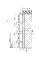
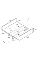
- FIG. 1 is a perspective view showing an overall configuration of a battery module according to an embodiment.
- 2 is a cross-sectional view of the battery module shown in FIG. 1 when cut along the X-axis direction so as to pass through all the through holes arranged in the X-axis direction.
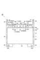
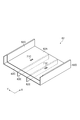
- FIG. 3 is a cross-sectional view of the battery module of FIG. 1 when cut along a plane orthogonal to the direction in which the secondary batteries are juxtaposed.
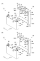
- 4A is a perspective view showing the first battery holder shown in FIG. 1
- FIG. 4B is a perspective view showing the second battery holder.
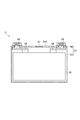
- FIG. 5 is a cross-sectional view showing a secondary battery included in the battery module of FIG.
- FIG. 6 is a perspective view showing the first cover member shown in FIG. FIG.
- FIG. 7 is a perspective view showing the second cover member shown in FIG. 1.
- FIG. 8 is a cross-sectional view showing a state in which each of the secondary batteries in FIG. 2 has expanded.
- FIG. 9 is a perspective view showing an overall configuration of a battery module according to another embodiment.
- FIG. 10 is a cross-sectional view of the battery module of FIG. 9 taken along the X-axis direction so as to pass through all the through holes arranged in the X-axis direction.
- the battery module 10 includes a plurality of secondary batteries (power storage devices) 11 such as lithium ion secondary batteries or nickel hydride storage batteries.
- Each of the secondary batteries 11 is arranged in parallel along the X-axis direction (one direction) while being held by the first battery holder (holding member) 21 or the second battery holder (holding member) 41. .
- a pair of end plates (clamping portions) 12A and 12B are provided at both ends of the battery module 10 in the X-axis direction.
- End plates 12B and intermediate plates (intermediate clamping portions) 15 are arranged at both ends of the plurality of secondary batteries 11 arranged in parallel in the X-axis direction.
- a rubber member (elastic body) 17 is arranged between the intermediate plate 15 and the end plate 12A.
- the bolt B is inserted through the pair of end plates 12A and 12B, the intermediate plate 15, the first battery holder 21 and the second battery holder 41.
- the bolt B is inserted from one end plate 12A toward the other end plate 12B, and is screwed into the nut N on the other end plate 12B side.
- the pair of end plates 12A and 12B pressurize and restrain the plurality of secondary batteries 11.
- the pair of end plates 12A and 12B maintain the length of the battery module 10 in the X-axis direction within a certain range.
- the first battery holder 21 and the second battery holder 41 are used.
- the first battery holder 21 and the second battery holder 41 are alternately arranged along one direction (X-axis direction).
- X-axis direction the thickness direction of the secondary battery 11
- the width direction the width direction (electrode terminal).
- the direction orthogonal to both the thickness direction and the width direction will be described as “X-axis direction”, “Y-axis direction”, and “height direction”, respectively.
- the first battery holder 21 includes a rectangular flat plate-shaped lower surface portion 22, a first side surface portion 23, a second side surface portion 24, a third side surface portion 25, a leg portion 29, and a terminal housing. It has a portion 31, a column member 33, a locking projection 38, and a protruding portion 26.
- the lower surface portion 22 is a portion that covers the bottom surface of the secondary battery 11 when holding the secondary battery 11.
- the 1st side surface part 23 and the 2nd side surface part 24 are arrange
- the first side surface portion 23 and the second side surface portion 24 are portions that cover the side surface of the secondary battery 11 (the surface along the stacking direction of the electrode assembly 52 shown in FIG. 5) when holding the secondary battery 11. is there.
- the third side surface portion 25 is provided so as to connect the first side surface portion 23 and the second side surface portion 24 with the thickness direction in the X-axis direction.
- the position of the upper end 25 ⁇ / b> A of the third side surface portion 25 coincides with the positions 23 ⁇ / b> A and 24 ⁇ / b> A of the upper ends of the first side surface portion 23 and the second side surface portion 24.
- the third side surface portion 25 is a part of one main surface of the secondary battery 11 (a surface orthogonal to the stacking direction of the electrodes constituting the electrode assembly 52 shown in FIG. 5) when holding the secondary battery 11. It is the part that covers.
- the leg portions 29 and 29 are provided at positions 23 ⁇ / b> C and 24 ⁇ / b> C of the respective lower end portions in the height direction of the first side surface portion 23 and the second side surface portion 24.
- the leg portion 29 is provided with an insertion hole 29A penetrating along the X-axis direction.
- the aforementioned bolt B is inserted through the insertion hole 29A.
- the terminal accommodating portions 31, 31 are provided at both ends in the Y-axis direction of the upper end 25A of the third side surface portion 25, respectively.
- the terminal accommodating portions 31 are provided so as to be connected to the first side surface portion 23 and the second side surface portion 24, respectively.
- the terminal accommodating portion 31 opens in a U shape in the X-axis direction.
- the terminal accommodating portion 31 is a portion that surrounds the electrode terminal 55 of the secondary battery 11 when holding the secondary battery 11.
- Each of the column members 33 and 33 is provided next to the terminal accommodating portions 31 and 31 at the upper end 25A of the third side surface portion 25.
- the column member 33 is a quadrangular columnar column member extending in the X-axis direction, and the length thereof matches the length of the lower surface portion 22 in the X-axis direction.
- the column member 33 is provided with an insertion hole 33A penetrating along the X-axis direction. The aforementioned bolt B is inserted through the insertion hole 33A.
- the locking projection 38 is provided at the upper end of the column member 33.
- the locking protrusion 38 protrudes from the column member 33 in the height direction in the direction opposite to the housing portion S1.
- a locking portion 38 ⁇ / b> A having a triangular prism shape is formed at the tip of the locking protrusion 38.
- the protruding portion 26 is provided at the upper end positions 23A and 24A of the first side surface portion 23 and the second side surface portion 24, respectively.
- the protrusions 26 are disposed so as to face each other and extend in the height direction.
- a protrusion 27 protruding in the Y-axis direction of the protruding portion 26 is provided on each surface where the protruding portions 26 face each other.
- the second battery holder 41 will be described. As shown in FIG. 4B, the second battery holder 41 has the same structure as the first battery holder 21 except that the second battery holder 41 does not have the locking protrusion 38. For this reason, the same code
- the electrode assembly 52 included in the secondary battery 11 held by the first battery holder 21 or the second battery holder 41 described above is housed inside the case 51.
- the electrode assembly 52 has a positive electrode and a negative electrode.
- the case 51 includes a bottomed box-shaped main body 53 that houses the electrode assembly 52 and a plate-shaped lid 54 that closes the opening of the main body 53.
- Electrode terminals 55 and 55 are provided on the upper surface (surface) 54 ⁇ / b> A of the lid portion 54.
- On the upper surface 54A of the lid portion 54 there is provided an open valve 57 that breaks and releases the internal pressure of the case 51 when the internal pressure of the case 51 rises to a threshold value.
- the “threshold value” is set such that when the internal pressure of the case 51 increases, the release valve 57 is broken before the case 51 is damaged by the internal pressure of the case 51.
- the electrode terminals 55 and 55 are electrically connected to the electrode assembly 52 via the conductive member 58.
- the battery module 10 includes a first cover member 61 and a second cover member 62 that cover the upper surface 54A of the lid portion 54 of the secondary battery 11 provided side by side in the X-axis direction. is doing.
- On the first cover member 61 and the second cover member 62 for example, electronic components that contribute to charging / discharging of the secondary battery 11, a battery ECU that controls the battery module 10, and the like are placed.
- the first cover member 61 and the second cover member 62 are resin cover members.
- the first cover member 61 and the second cover member 62 are provided side by side in the X-axis direction.
- the first cover member 61 has one end 61F in the X-axis direction fixed to the end plate 12B.
- the second cover member 62 has one end 62 ⁇ / b> F in the X-axis direction fixed to the intermediate plate 15.
- the first cover member 61 has a main body portion 61A, a pair of standing portions 61D and 61D, and a pair of extending portions 61E and 61E.
- the second cover member 62 is the same as the first cover member 61 except that the positions and the number of through holes provided in the main body portion 62A and the length in the X-axis direction are different. It has a configuration.
- the first cover member 61 will be described in detail.
- the main body 61 ⁇ / b> A is provided so as to face the upper surface 54 ⁇ / b> A of the lid 54 in the secondary battery 11 (see FIG. 3).
- the main body 61A is formed in a rectangular flat plate shape.
- the pair of standing portions 61D and 61D are provided at both ends in the Y-axis direction of the main body portion 61A.
- the pair of upright portions 61D and 61D are provided upright in the height direction in the main body portion 61A and face each other.
- the pair of extending portions 61E and 61E are provided on the surface of the main body portion 61A opposite to the surface on which the standing portions 61D and 61D are provided.
- the pair of extending portions 61E and 61E project downward from the main body portion 61A in the height direction, and are disposed so as to face each other with the open valve 57 of the secondary battery 11 in between (see FIG. 3). Further, the pair of extending portions 61E and 61E extend in the X-axis direction (one direction) of the main body portion 61A.
- the pair of extending portions 61E and 61E protrude from the main body portion 61A to the lid portion 54 side of the secondary battery 11 and are in contact with the upper surface 54A of the lid portion 54 (see FIG. 3).
- the main body 61A is provided on the upper surface 54A of the lid 54 via the pair of extending portions 61E and 61E.
- the first cover member 61 and the second cover member 62 extend in the X-axis direction surrounded by the main body portions 61A and 62A, the extension portions 61E and 62E, and the upper surface 54A of the lid portion 54.
- the space forms a flow passage 81 for the gas discharged from the release valve 57.
- the release valve 57 is exposed in the flow passage 81. For this reason, when the gas is discharged from the release valve 57, the gas is discharged into the flow passage 81, and the gas flows along the extending direction of the flow passage 81.
- the flow passage 81 extends to the end plates 12A and 12B provided at both ends of the secondary battery 11 in the juxtaposed direction.
- the end of the first cover member 61 on the second cover member 62 side in the X-axis direction, and the end of the second cover member 62 on the first cover member 61 side in the X-axis direction Are formed with overlapping portions 61 ⁇ / b> C and 62 ⁇ / b> C that allow the first cover member 61 and the second cover member 62 to be disposed so as to overlap each other. Even if the second cover member 62 moves relative to the first cover member 61 by the overlapping portions 61C and 62C, the upper surface 54A of the lid portion 54 and the first cover member 61 and the second cover member 62 The sealing of the space between them is maintained.
- four through holes 71 ⁇ / b> A, 71 ⁇ / b> A, 71 ⁇ / b> B, 71 ⁇ / b> B are formed in the main body 61 ⁇ / b> A of the first cover member 61 so as to penetrate in the thickness direction of the main body 61 ⁇ / b> A.
- the locking protrusion 38 of the first battery holder 21 is passed through the through holes 71 ⁇ / b> A and 71 ⁇ / b> B.
- the first cover member 61 is fixed to the first battery holder 21 by locking the locking portions 38A of the locking protrusions 38 in the through holes 71A and 71B.
- the main body 62A of the second cover member 62 is formed with two through holes 71C and 71C that penetrate in the thickness direction of the main body 62A.
- the locking protrusion 38 of the first battery holder 21 is passed through the through hole 71 ⁇ / b> C.
- the second cover member 62 is also fixed to the first battery holder 21 by locking the locking portion 38 ⁇ / b> A of the locking protrusion 38 in the through hole 71 ⁇ / b> C.
- the length L of the through holes 71A and 71B in the X-axis direction of the first cover member 61 is a fixed portion between the first cover member 61 and the end plate 12B.
- the end portion 61F (hereinafter also referred to as “fixed portion 61F”) is formed so as to become longer according to the distance D.
- the length L of the through hole 71 ⁇ / b> C in the X-axis direction of the second cover member 62 is from one end 62 ⁇ / b> F (hereinafter also referred to as “fixed part 62 ⁇ / b> F”) that is a fixed part to the intermediate plate 15. It is formed so as to become longer according to the distance D.
- the distance D from the fixing portion 61F to the through hole 71A and the through hole 71B is a distance D1 and a distance D2, respectively.
- a distance D from the fixing portion 62F to the through hole 71C is a distance D3.
- the relationship between the lengths of the distances D1, D2, and D3 is distance D2> distance D3> distance D1.
- the lengths L1, L2, and L3 of the through holes 71A, 71B, and 71C in the X-axis direction are formed according to the distances D1, D2, and D3. That is, the relationship between the lengths L1, L2, and L3 of the through holes 71A, 71B, and 71C in the X-axis direction is length L2> length L3> length L1.
- the secondary battery 11 may expand with repeated charge / discharge or deterioration.
- the plurality of secondary batteries 11 are sandwiched and restrained while being pressed by the pair of end plates 12 ⁇ / b> A and 12 ⁇ / b> B, thereby forming the battery module 10 as a whole. Expansion is prevented from exceeding a predetermined amount.
- the rubber member 17 is disposed between the pair of end plates 12A and 12B, the predetermined amount of expansion that occurs in the plurality of secondary batteries 11 is shown in FIG. Thus, it is absorbed by the rubber member 17.
- the first cover member 61 has a fixing portion 61F fixed to the end plate 12B.
- the locking protrusion 38 provided on the first battery holder 21 moves in a direction away from the end plate 12B (right direction shown in FIG. 8).
- the locking protrusions 38 move through the through holes 71A and 71B formed in the shape of long holes along the direction in which the secondary batteries 11 are arranged side by side.
- the through holes 71A and 71B of the present embodiment have a length L corresponding to these movement distances. Is formed. Therefore, even when the secondary battery 11 is expanded, the movement of the locking projection 38 is not restricted by the through holes 71A and 71B.
- the second cover member 62 has a fixing portion 62F fixed to the intermediate plate 15.
- the locking protrusion 38 provided on the first battery holder 21 moves in a direction approaching the end plate 12A (right direction shown in FIG. 8).
- the locking protrusion 38 moves in the through hole 71 ⁇ / b> C formed in the shape of a long hole along the parallel direction of the secondary batteries 11.
- the through hole 71C of this embodiment is formed to have a length L corresponding to these movement distances. ing. Therefore, even when the secondary battery 11 is expanded, the movement of the locking protrusion 38 is not restricted by the through hole 71C.
- each of the through holes 71A, 71B, 71C for inserting and locking the locking projections 38 is in the X-axis direction, that is, two
- the secondary battery 11 extends in the expansion direction.
- the locking projection 38 of the first battery holder 21 moves in the expansion direction due to the expansion of the secondary battery 11
- the locking projection 38 moves in the through holes 71A, 71B, 71C.
- the movement in the expansion direction is not restricted.
- the locking projection 38 or the locking projection 38 for fixing the first cover member 61 and the second cover member 62 to the first battery holder 21 is locked. It can suppress that the 1st cover member 61 and the 2nd cover member 62 to be damaged are damaged.
- the secondary of the first cover member 61 and the second cover member 62 is matched with the amount of movement of the locking protrusion 38 of the first battery holder 21 when the secondary battery 11 is expanded.
- a length L in the direction in which the batteries 11 are arranged side by side is set.
- the battery module 10 of the above embodiment may have a configuration in which three cover members are arranged in parallel in the direction in which the secondary batteries 11 are arranged.
- the battery module according to the first modification will be described as the battery module 110.
- the battery module 110 includes a first cover member 161, a second cover member 162, and an intermediate cover member 168 that are disposed to face the upper surface 54 ⁇ / b> A of the lid portion 54 provided with the electrode terminals 55, 55 of the secondary battery 11. is doing.
- the first cover member 161, the second cover member 162, and the intermediate cover member 168 are different from the above-described embodiment, and are examples of flat plate-like cover members that do not have a standing portion and an extending portion. However, you may have a standing part and an extension part.
- the main body portion 161A of the first cover member 161 is formed with four through holes 171A, 171A, 171B, and 171B that penetrate in the thickness direction (vertical direction) of the main body portion 161A.
- a locking projection 38 of the first battery holder 21 is passed through each of the through holes 171A and 171B provided in the main body portion 161A of the first cover member 161.
- the first cover member 161 is fixed to the first battery holder 21 by locking the locking portions 38A of the locking projections 38 in the through holes 171A and 171B.
- through holes 171D, 171D, 171E, and 171E are formed in the main body 162A of the second cover member 162 so as to penetrate in the thickness direction of the main body 162A.
- the locking projections 38 of the first battery holder 21 are passed through the through holes 171D and 171E provided in the main body portion 162A of the second cover member 162, respectively.
- the second cover member 162 is also fixed to the first battery holder 21 by locking the locking portions 38A of the locking projections 38 in the through holes 171D and 171E.
- Two through holes 171C and 171C are formed in the main body 168A of the intermediate cover member 168 so as to penetrate in the thickness direction of the main body 168A.
- the locking protrusion 38 of the first battery holder 21 is passed through the through-hole 171C provided in the main body 168A of the intermediate cover member 168.
- the intermediate cover member 168 is also fixed to the first battery holder 21 by locking the locking portion 38 ⁇ / b> A of the locking projection 38 in the through hole 171 ⁇ / b> C.
- the first cover member 161 and the intermediate cover member 168 have overlapping portions 161B and 168B that overlap each other.
- the overlapping portion 161B of the first cover member 161 is formed at the end opposite to the portion fixed to the end plate 12B.
- the second cover member 162 and the intermediate cover member 168 have overlapping portions 162C and 168C that overlap each other.
- the overlapping portion 162 ⁇ / b> C in the second cover member 162 is formed at the end opposite to the portion fixed to the intermediate plate 15.
- the intermediate cover member 168 In the intermediate cover member 168, overlapping portions 168B and 168C at both ends in the X-axis direction are placed on the overlapping portions 161B and 162C of the first cover member 161 and the second cover member 162, respectively. That is, the intermediate cover member 168 is provided so as to be movable relative to the first cover member 161 and the second cover member 162 in the X-axis direction.
- a control device 93 for controlling a thermistor (temperature sensor) 91 for monitoring the temperature of the secondary battery 11 is placed.
- the control device 93 is disposed at a position between the two through holes 171 ⁇ / b> C in the Y-axis direction in the main body 168 ⁇ / b> A of the intermediate cover member 168.
- the thermistor 91 is fixed to the first battery holder 21 that holds the secondary battery 11.
- the length L of the through holes 171A and 171B in the X-axis direction of the first cover member 161 is the same as that of the first cover member 161 and the other. It is formed so as to become longer according to a distance D from one end portion 161F (hereinafter also referred to as “fixed portion 161F”) which is a fixed portion to the end plate 12B. That is, length L12> length L11 with respect to the relationship of distance D12> distance D11.
- the length L of the through hole 171 ⁇ / b> C in the X-axis direction of the second cover member 162 is from one end 162 ⁇ / b> F (hereinafter also referred to as “fixed portion 162 ⁇ / b> F”) that is a fixed portion with the intermediate plate 15. It is formed so as to become longer according to the distance D. That is, for the relationship of distance D14> distance D15, length L14> length L15.
- the length L (L13) of the through hole 171C in the X-axis direction of the intermediate cover member 168 is formed substantially the same as the length of the locking protrusion 38 of the first battery holder 21 in the X-axis direction.
- the through holes 171A, 171B, 171D, and 171E for inserting and locking the locking projections 38 are in the X-axis direction, that is, similarly to the battery module 10 of the above embodiment.
- the secondary battery 11 is formed in a long hole shape in the expansion direction. Further, the lengths of the through holes 171A, 171B, 171D, and 171E of the first cover member 161 and the second cover member 162 are adjusted in accordance with the amount of movement of the locking protrusion 38 of the first battery holder 21 when the secondary battery 11 is expanded. L is set.
- the locking protrusion 38 or the locking protrusion 38 for fixing the first cover member 161 and the second cover member 162 to the first battery holder 21 is locked. It can suppress that the 1st cover member 161 and the 2nd cover member 162 to be damaged are damaged.
- the intermediate cover member 168 is placed on the overlapping portions 161B and 162C of the first cover member 161 and the second cover member 162, and the first battery holder 21 is engaged with the through hole 171C.
- the stop protrusion 38 is inserted without a gap.
- the intermediate cover member 168 also moves integrally. Since the intermediate cover member 168 is merely placed on the overlapping portions 161B and 162C of the first cover member 161 and the second cover member 162, movement in the expansion direction is not hindered.
- the intermediate cover member 168 on which the control device 93 of the thermistor 91 is mounted is fixed to the locking protrusion 38 of the first battery holder 21 to which the thermistor 91 is fixed.
- the relative position of the control device 93 does not change significantly. That is, the intermediate cover member 168 moves with the movement of the first battery holder 21 to which the thermistor 91 is fixed. For this reason, malfunctions, such as the wiring which connects the thermistor 91 and the control apparatus 93 being disconnected, are suppressed.
- the battery module 110 in the first modification has been described with an example in which one intermediate cover member is placed on the cover member fixed to the end plate or the intermediate plate. However, two or more intermediate cover members are arranged. May be.
- the cover members such as the first, second, and intermediate cover members are standardized by aligning the lengths in the direction in which the secondary batteries 11 are juxtaposed, a plurality of types of battery modules having different capacities can be used as common parts. Can be manufactured. Thereby, it becomes possible to manufacture a plurality of types of battery modules at low cost.
- the battery modules 10 and 110 have been described with reference to the example in which the intermediate plate 15 is disposed, the present invention is not limited to this.
- a battery module having a configuration in which a plurality of secondary batteries 11 are directly sandwiched between end plates 12 and 12 may be used.
- the length L in the X-axis direction of the through holes 71A, 71B, 71C formed in the first cover member 61 and the second cover member 62 is the other end plate 12B or intermediate plate 15.
- a through hole that extends uniformly in the X-axis direction, that is, in the direction in which the secondary batteries 11 are juxtaposed may be used regardless of the distance from the fixing portions 61F and 62F to the other end plate 12B or the intermediate plate 15.
- the battery module 10 may have a configuration in which one cover member is disposed.
- the cover member is fixed to one of the pair of end plates 12 ⁇ / b> A and 12 ⁇ / b> B or the intermediate plate 15.
- All of the through holes formed in the main body portion of the cover member may be formed in a long hole shape along the direction in which the secondary batteries 11 are juxtaposed, or the pair of end plates 12A, 12B or the intermediate plate 15 may be formed.
- a length corresponding to the distance from the fixed portion (the longer the position from the fixed portion, the longer the length).
- the locking protrusion 38 may be provided on both the first battery holder 21 and the second battery holder 41. That is, only the first battery holder 21 may be used. In this case, even if the number of the through holes 71A, 71B, 71C of the first cover member 61 and the second cover member 62 is changed in accordance with the number of the locking projections 38 of the first battery holder 21 and the second battery holder 41. Good.
Landscapes
- Chemical & Material Sciences (AREA)
- Chemical Kinetics & Catalysis (AREA)
- Electrochemistry (AREA)
- General Chemical & Material Sciences (AREA)
- Engineering & Computer Science (AREA)
- Manufacturing & Machinery (AREA)
- Battery Mounting, Suspending (AREA)
Priority Applications (3)
| Application Number | Priority Date | Filing Date | Title |
|---|---|---|---|
| DE112015004307.1T DE112015004307T5 (de) | 2014-09-22 | 2015-08-18 | Energiespeichermodul |
| US15/512,406 US10186694B2 (en) | 2014-09-22 | 2015-08-18 | Power storage module |
| CN201580050934.9A CN106716674B (zh) | 2014-09-22 | 2015-08-18 | 蓄电模块 |
Applications Claiming Priority (2)
| Application Number | Priority Date | Filing Date | Title |
|---|---|---|---|
| JP2014-192705 | 2014-09-22 | ||
| JP2014192705A JP6303951B2 (ja) | 2014-09-22 | 2014-09-22 | 蓄電モジュール |
Publications (1)
| Publication Number | Publication Date |
|---|---|
| WO2016047318A1 true WO2016047318A1 (ja) | 2016-03-31 |
Family
ID=55580849
Family Applications (1)
| Application Number | Title | Priority Date | Filing Date |
|---|---|---|---|
| PCT/JP2015/073162 Ceased WO2016047318A1 (ja) | 2014-09-22 | 2015-08-18 | 蓄電モジュール |
Country Status (5)
| Country | Link |
|---|---|
| US (1) | US10186694B2 (enExample) |
| JP (1) | JP6303951B2 (enExample) |
| CN (1) | CN106716674B (enExample) |
| DE (1) | DE112015004307T5 (enExample) |
| WO (1) | WO2016047318A1 (enExample) |
Families Citing this family (18)
| Publication number | Priority date | Publication date | Assignee | Title |
|---|---|---|---|---|
| JP2018037184A (ja) * | 2016-08-30 | 2018-03-08 | 株式会社豊田自動織機 | 電池モジュール |
| JP6819159B2 (ja) * | 2016-09-08 | 2021-01-27 | 株式会社豊田自動織機 | 電池モジュール |
| JP6790714B2 (ja) * | 2016-10-20 | 2020-11-25 | 株式会社豊田自動織機 | 電池モジュール |
| US11065979B1 (en) | 2017-04-05 | 2021-07-20 | H55 Sa | Aircraft monitoring system and method for electric or hybrid aircrafts |
| US11148819B2 (en) | 2019-01-23 | 2021-10-19 | H55 Sa | Battery module for electrically-driven aircraft |
| US12409756B2 (en) | 2017-04-05 | 2025-09-09 | H55 Sa | Aircraft monitoring system and method for electric or hybrid aircrafts |
| US11063323B2 (en) | 2019-01-23 | 2021-07-13 | H55 Sa | Battery module for electrically-driven aircraft |
| US10479223B2 (en) | 2018-01-25 | 2019-11-19 | H55 Sa | Construction and operation of electric or hybrid aircraft |
| KR102184368B1 (ko) * | 2017-12-11 | 2020-11-30 | 삼성에스디아이 주식회사 | 배터리 팩 |
| JP6921728B2 (ja) * | 2017-12-13 | 2021-08-18 | プライムアースEvエナジー株式会社 | 電池パック用スペーサ及び電池パック |
| DE102018102142A1 (de) | 2018-01-31 | 2019-08-01 | stoba e-Systems GmbH | Energiespeichermodul mit über unisolierte Leiterstücke verbundenen Energiespeicherzellen und/oder einem Kühlsystem, Energiespeicherblock und Verfahren zum Kühlen eines Energiespeichermoduls |
| JP7207814B2 (ja) * | 2018-03-30 | 2023-01-18 | 三洋電機株式会社 | 電源装置と電源装置を備える電動車両 |
| KR102694746B1 (ko) * | 2019-01-10 | 2024-08-12 | 주식회사 엘지에너지솔루션 | 전지팩 제조방법 |
| WO2020208527A1 (en) | 2019-04-08 | 2020-10-15 | H55 Sa | Power supply storage and fire management in electrically-driven aircraft |
| CN112582719B (zh) | 2019-09-29 | 2022-04-29 | 东莞新能源科技有限公司 | 电池模组单元、电池模组、储能系统及电动车辆 |
| KR20220041470A (ko) * | 2020-09-25 | 2022-04-01 | 현대자동차주식회사 | 배터리 모듈 및 이를 포함하는 배터리 팩 |
| JP7517258B2 (ja) * | 2021-06-15 | 2024-07-17 | トヨタ自動車株式会社 | 樹脂枠および電池モジュール |
| JP7570387B2 (ja) * | 2022-10-20 | 2024-10-21 | プライムプラネットエナジー&ソリューションズ株式会社 | 電池モジュール |
Citations (6)
| Publication number | Priority date | Publication date | Assignee | Title |
|---|---|---|---|---|
| JP2012064356A (ja) * | 2010-09-14 | 2012-03-29 | Honda Motor Co Ltd | 電池モジュール |
| JP2012160347A (ja) * | 2011-01-31 | 2012-08-23 | Sanyo Electric Co Ltd | 電源装置及び電源装置を備える車両 |
| WO2012147150A1 (ja) * | 2011-04-25 | 2012-11-01 | 日立ビークルエナジー株式会社 | 組電池および単電池 |
| JP2013084444A (ja) * | 2011-10-08 | 2013-05-09 | Sanyo Electric Co Ltd | 電源装置及びこの電源装置を備える車両 |
| WO2014119722A1 (ja) * | 2013-01-31 | 2014-08-07 | 株式会社 豊田自動織機 | 電池モジュール |
| WO2015033795A1 (ja) * | 2013-09-05 | 2015-03-12 | 株式会社 豊田自動織機 | 電池モジュール |
Family Cites Families (5)
| Publication number | Priority date | Publication date | Assignee | Title |
|---|---|---|---|---|
| JP5151363B2 (ja) * | 2007-09-28 | 2013-02-27 | 三菱自動車工業株式会社 | 電気自動車用バッテリケース |
| JP5612904B2 (ja) * | 2010-05-13 | 2014-10-22 | 矢崎総業株式会社 | カバー部材及び該カバー部材を備えた電源装置 |
| JP2012243534A (ja) | 2011-05-18 | 2012-12-10 | Sanyo Electric Co Ltd | 電池積層構造体及びこれを備える車両並びに電池積層構造体用のバインドバー |
| US9634302B2 (en) * | 2011-11-18 | 2017-04-25 | Hitachi Automotive Systems, Ltd. | Secondary battery module |
| KR20150024724A (ko) * | 2013-08-27 | 2015-03-09 | 삼성에스디아이 주식회사 | 배터리 팩 |
-
2014
- 2014-09-22 JP JP2014192705A patent/JP6303951B2/ja not_active Expired - Fee Related
-
2015
- 2015-08-18 WO PCT/JP2015/073162 patent/WO2016047318A1/ja not_active Ceased
- 2015-08-18 CN CN201580050934.9A patent/CN106716674B/zh not_active Expired - Fee Related
- 2015-08-18 US US15/512,406 patent/US10186694B2/en not_active Expired - Fee Related
- 2015-08-18 DE DE112015004307.1T patent/DE112015004307T5/de not_active Withdrawn
Patent Citations (6)
| Publication number | Priority date | Publication date | Assignee | Title |
|---|---|---|---|---|
| JP2012064356A (ja) * | 2010-09-14 | 2012-03-29 | Honda Motor Co Ltd | 電池モジュール |
| JP2012160347A (ja) * | 2011-01-31 | 2012-08-23 | Sanyo Electric Co Ltd | 電源装置及び電源装置を備える車両 |
| WO2012147150A1 (ja) * | 2011-04-25 | 2012-11-01 | 日立ビークルエナジー株式会社 | 組電池および単電池 |
| JP2013084444A (ja) * | 2011-10-08 | 2013-05-09 | Sanyo Electric Co Ltd | 電源装置及びこの電源装置を備える車両 |
| WO2014119722A1 (ja) * | 2013-01-31 | 2014-08-07 | 株式会社 豊田自動織機 | 電池モジュール |
| WO2015033795A1 (ja) * | 2013-09-05 | 2015-03-12 | 株式会社 豊田自動織機 | 電池モジュール |
Also Published As
| Publication number | Publication date |
|---|---|
| CN106716674A (zh) | 2017-05-24 |
| CN106716674B (zh) | 2019-07-19 |
| JP6303951B2 (ja) | 2018-04-04 |
| DE112015004307T5 (de) | 2017-06-08 |
| US20170279094A1 (en) | 2017-09-28 |
| US10186694B2 (en) | 2019-01-22 |
| JP2016062880A (ja) | 2016-04-25 |
Similar Documents
| Publication | Publication Date | Title |
|---|---|---|
| JP6303951B2 (ja) | 蓄電モジュール | |
| JP5737351B2 (ja) | 電池モジュール | |
| JP5590165B2 (ja) | 電池モジュール | |
| JP5949796B2 (ja) | 接続ユニット | |
| CN105470420B (zh) | 蓄电装置 | |
| CN110998908B (zh) | 约束部件以及电池模块 | |
| WO2020166182A1 (ja) | 電池モジュール | |
| JP7149540B2 (ja) | 拘束部材および電池モジュール | |
| JP6390721B2 (ja) | 電池パック | |
| US20140356664A1 (en) | Battery module | |
| JP6629140B2 (ja) | 蓄電モジュール | |
| JP2018200856A (ja) | 蓄電デバイス | |
| CN113795976A (zh) | 汇流条板 | |
| CN112740472B (zh) | 蓄电装置以及蓄电模块 | |
| JP7134626B2 (ja) | 蓄電装置 | |
| JP6819159B2 (ja) | 電池モジュール | |
| JPWO2019044581A1 (ja) | 電池パック | |
| JP2014212026A (ja) | 電池モジュール | |
| JP7307069B2 (ja) | 電池モジュールの固定構造 | |
| KR20170052990A (ko) | 배터리 모듈 및 이러한 배터리 모듈을 포함하는 배터리 팩 및 이러한 배터리 팩을 포함하는 자동차 | |
| JP2017063052A (ja) | 電池モジュール及び電池パック | |
| CN112335113A (zh) | 蓄电装置 | |
| JP2018063827A (ja) | 電池モジュールの製造方法 | |
| JP6790714B2 (ja) | 電池モジュール | |
| CN114930626A (zh) | 电池组件 |
Legal Events
| Date | Code | Title | Description |
|---|---|---|---|
| 121 | Ep: the epo has been informed by wipo that ep was designated in this application |
Ref document number: 15843734 Country of ref document: EP Kind code of ref document: A1 |
|
| WWE | Wipo information: entry into national phase |
Ref document number: 15512406 Country of ref document: US |
|
| WWE | Wipo information: entry into national phase |
Ref document number: 112015004307 Country of ref document: DE |
|
| 122 | Ep: pct application non-entry in european phase |
Ref document number: 15843734 Country of ref document: EP Kind code of ref document: A1 |