WO2016042848A1 - 電池モジュール - Google Patents
電池モジュール Download PDFInfo
- Publication number
- WO2016042848A1 WO2016042848A1 PCT/JP2015/065273 JP2015065273W WO2016042848A1 WO 2016042848 A1 WO2016042848 A1 WO 2016042848A1 JP 2015065273 W JP2015065273 W JP 2015065273W WO 2016042848 A1 WO2016042848 A1 WO 2016042848A1
- Authority
- WO
- WIPO (PCT)
- Prior art keywords
- harness
- binding
- battery cell
- binding member
- battery
- Prior art date
- Legal status (The legal status is an assumption and is not a legal conclusion. Google has not performed a legal analysis and makes no representation as to the accuracy of the status listed.)
- Ceased
Links
Images


Classifications
-
- H—ELECTRICITY
- H01—ELECTRIC ELEMENTS
- H01M—PROCESSES OR MEANS, e.g. BATTERIES, FOR THE DIRECT CONVERSION OF CHEMICAL ENERGY INTO ELECTRICAL ENERGY
- H01M50/00—Constructional details or processes of manufacture of the non-active parts of electrochemical cells other than fuel cells, e.g. hybrid cells
- H01M50/50—Current conducting connections for cells or batteries
- H01M50/502—Interconnectors for connecting terminals of adjacent batteries; Interconnectors for connecting cells outside a battery casing
-
- H—ELECTRICITY
- H01—ELECTRIC ELEMENTS
- H01M—PROCESSES OR MEANS, e.g. BATTERIES, FOR THE DIRECT CONVERSION OF CHEMICAL ENERGY INTO ELECTRICAL ENERGY
- H01M10/00—Secondary cells; Manufacture thereof
- H01M10/05—Accumulators with non-aqueous electrolyte
- H01M10/052—Li-accumulators
- H01M10/0525—Rocking-chair batteries, i.e. batteries with lithium insertion or intercalation in both electrodes; Lithium-ion batteries
-
- H—ELECTRICITY
- H01—ELECTRIC ELEMENTS
- H01M—PROCESSES OR MEANS, e.g. BATTERIES, FOR THE DIRECT CONVERSION OF CHEMICAL ENERGY INTO ELECTRICAL ENERGY
- H01M50/00—Constructional details or processes of manufacture of the non-active parts of electrochemical cells other than fuel cells, e.g. hybrid cells
- H01M50/20—Mountings; Secondary casings or frames; Racks, modules or packs; Suspension devices; Shock absorbers; Transport or carrying devices; Holders
- H01M50/256—Carrying devices, e.g. belts
-
- H—ELECTRICITY
- H01—ELECTRIC ELEMENTS
- H01M—PROCESSES OR MEANS, e.g. BATTERIES, FOR THE DIRECT CONVERSION OF CHEMICAL ENERGY INTO ELECTRICAL ENERGY
- H01M50/00—Constructional details or processes of manufacture of the non-active parts of electrochemical cells other than fuel cells, e.g. hybrid cells
- H01M50/10—Primary casings; Jackets or wrappings
- H01M50/172—Arrangements of electric connectors penetrating the casing
- H01M50/174—Arrangements of electric connectors penetrating the casing adapted for the shape of the cells
- H01M50/176—Arrangements of electric connectors penetrating the casing adapted for the shape of the cells for prismatic or rectangular cells
-
- H—ELECTRICITY
- H01—ELECTRIC ELEMENTS
- H01M—PROCESSES OR MEANS, e.g. BATTERIES, FOR THE DIRECT CONVERSION OF CHEMICAL ENERGY INTO ELECTRICAL ENERGY
- H01M50/00—Constructional details or processes of manufacture of the non-active parts of electrochemical cells other than fuel cells, e.g. hybrid cells
- H01M50/20—Mountings; Secondary casings or frames; Racks, modules or packs; Suspension devices; Shock absorbers; Transport or carrying devices; Holders
- H01M50/204—Racks, modules or packs for multiple batteries or multiple cells
- H01M50/207—Racks, modules or packs for multiple batteries or multiple cells characterised by their shape
- H01M50/209—Racks, modules or packs for multiple batteries or multiple cells characterised by their shape adapted for prismatic or rectangular cells
-
- H—ELECTRICITY
- H01—ELECTRIC ELEMENTS
- H01M—PROCESSES OR MEANS, e.g. BATTERIES, FOR THE DIRECT CONVERSION OF CHEMICAL ENERGY INTO ELECTRICAL ENERGY
- H01M50/00—Constructional details or processes of manufacture of the non-active parts of electrochemical cells other than fuel cells, e.g. hybrid cells
- H01M50/50—Current conducting connections for cells or batteries
- H01M50/502—Interconnectors for connecting terminals of adjacent batteries; Interconnectors for connecting cells outside a battery casing
- H01M50/507—Interconnectors for connecting terminals of adjacent batteries; Interconnectors for connecting cells outside a battery casing comprising an arrangement of two or more busbars within a container structure, e.g. busbar modules
-
- H—ELECTRICITY
- H01—ELECTRIC ELEMENTS
- H01M—PROCESSES OR MEANS, e.g. BATTERIES, FOR THE DIRECT CONVERSION OF CHEMICAL ENERGY INTO ELECTRICAL ENERGY
- H01M50/00—Constructional details or processes of manufacture of the non-active parts of electrochemical cells other than fuel cells, e.g. hybrid cells
- H01M50/50—Current conducting connections for cells or batteries
- H01M50/531—Electrode connections inside a battery casing
-
- H—ELECTRICITY
- H01—ELECTRIC ELEMENTS
- H01M—PROCESSES OR MEANS, e.g. BATTERIES, FOR THE DIRECT CONVERSION OF CHEMICAL ENERGY INTO ELECTRICAL ENERGY
- H01M50/00—Constructional details or processes of manufacture of the non-active parts of electrochemical cells other than fuel cells, e.g. hybrid cells
- H01M50/50—Current conducting connections for cells or batteries
- H01M50/543—Terminals
- H01M50/547—Terminals characterised by the disposition of the terminals on the cells
- H01M50/55—Terminals characterised by the disposition of the terminals on the cells on the same side of the cell
-
- H—ELECTRICITY
- H01—ELECTRIC ELEMENTS
- H01M—PROCESSES OR MEANS, e.g. BATTERIES, FOR THE DIRECT CONVERSION OF CHEMICAL ENERGY INTO ELECTRICAL ENERGY
- H01M50/00—Constructional details or processes of manufacture of the non-active parts of electrochemical cells other than fuel cells, e.g. hybrid cells
- H01M50/50—Current conducting connections for cells or batteries
- H01M50/543—Terminals
- H01M50/552—Terminals characterised by their shape
- H01M50/553—Terminals adapted for prismatic, pouch or rectangular cells
-
- Y—GENERAL TAGGING OF NEW TECHNOLOGICAL DEVELOPMENTS; GENERAL TAGGING OF CROSS-SECTIONAL TECHNOLOGIES SPANNING OVER SEVERAL SECTIONS OF THE IPC; TECHNICAL SUBJECTS COVERED BY FORMER USPC CROSS-REFERENCE ART COLLECTIONS [XRACs] AND DIGESTS
- Y02—TECHNOLOGIES OR APPLICATIONS FOR MITIGATION OR ADAPTATION AGAINST CLIMATE CHANGE
- Y02E—REDUCTION OF GREENHOUSE GAS [GHG] EMISSIONS, RELATED TO ENERGY GENERATION, TRANSMISSION OR DISTRIBUTION
- Y02E60/00—Enabling technologies; Technologies with a potential or indirect contribution to GHG emissions mitigation
- Y02E60/10—Energy storage using batteries
Definitions
- the present invention relates to a battery module.
- a battery module in which a plurality of battery cells such as lithium ion secondary batteries are arranged is known.
- the battery cell array is sandwiched by a restraining tool such as a metal plate and restrained by a constant load, thereby suppressing fluctuations in characteristics such as internal resistance in the battery cell.
- a restraining tool such as a metal plate
- a constant load thereby suppressing fluctuations in characteristics such as internal resistance in the battery cell.
- a metal band having bent portions at both ends is fixed to an end plate, and the battery block is constrained in the stacking direction by the end plate.
- an elastic body such as rubber may be interposed between the array body and the end plate of the restraining member for the purpose of preventing damage to the restraining member due to expansion of the battery cell.
- a harness used for voltage detection of each battery cell may be assembled to the battery module.
- a connector having a voltage detection terminal is held by a holding member, and the holding member is attached to a battery group, so that the connector is electrically connected to the electrode terminals of the battery cells. Connected to.
- the proximal ends of the plurality of harnesses are bundled with a bundling member and assembled to the battery module in a harness bundle state. Further, when connecting the connection terminal at the tip of the harness to the electrode terminal of the battery cell, the lengths of the harnesses branched at the tip end side of the binding member may be different from each other so that the connection destination is not mistaken.
- the present invention has been made to solve the above problems, and an object of the present invention is to provide a battery module capable of suppressing a load applied to a harness even when the battery cell is expanded.
- a battery module includes an array formed by arraying a plurality of battery cells, a battery cell in the array extending along the array direction, and a connection at the tip.
- a plurality of harnesses each having a terminal connected to an electrode terminal of a predetermined battery cell; and a binding member that binds the plurality of harnesses to form a harness bundle.
- the binding position of the harness by the binding member, the electrode terminal, and the connection terminal The harness that branches off from the binding member has a deflection between the connection position and the connection position.
- the harness branched from the binding member is bent between the binding position of the harness by the binding member and the connection position of the electrode terminal and the connection terminal. For this reason, even if the battery cell expands and the connection position between the battery cell electrode terminal and the harness connection terminal moves relative to the binding position of the harness, the harness branching on the leading end side of the binding member It is possible to prevent the length from being insufficient. Therefore, it can suppress that a load is applied to a harness and generation
- the battery module further includes an elastic body disposed at one array end of the battery cells in the array body, and a restraining member that restrains the array body in the array direction via the elastic body, and the plurality of harnesses include:
- the binding position of the harness by the binding member may be located closer to the elastic body than the connection position between the electrode terminal and the connection terminal.
- the connection position between the electrode terminal and the connection terminal when the battery cell is expanded moves in one direction from the initial position to the elastic body side. Therefore, by positioning the binding position of the harness by the binding member closer to the elastic body than the connection position between the electrode terminal and the connection terminal, the connection position between the electrode terminal of the battery cell and the connection terminal of the harness is relative to the binding position of the harness. Even if it moves, it can prevent suitably that the length of the harness which branches on the front end side of a binding member runs short.
- the binding position of the harness by the binding member may be located closer to the elastic body than the connection position between the electrode terminal and the connection terminal when the connection destination battery cell is expanded.
- the bending amount of the harness branched from the binding member may be increased as the battery cell to which the harness is connected is positioned on the elastic body side.
- the amount of movement of the connection position between the electrode terminal of the battery cell and the connection terminal of the harness relative to the binding position of the harness becomes larger as the battery cell is positioned on the elastic body side. Therefore, by increasing the bending amount of the harness branched from the binding member as the battery cell to which the harness is connected is located on the elastic body side, the connection position between the electrode terminal of the battery cell and the connection terminal of the harness is increased. Even when the harness moves with respect to the binding position of the harness, it is possible to more reliably prevent the harness that branches off at the leading end side of the binding member from becoming insufficient.
- each of the harnesses may be provided with a mark indicating a binding position by the binding member.
- the binding position of the harness by the binding member can be easily grasped. Therefore, variation in the binding range for each harness can be suppressed, and the length of the harness that branches off at the front end side of the binding member can be more reliably ensured.
- the harness may be a harness used for detecting the voltage of the battery cell.
- the above-described harness arrangement is suitable for the harness arrangement used for voltage detection of the battery cell.
- the battery module according to the present invention can suppress the load applied to the harness even when the battery cell expands.
- FIG. 5 is an enlarged schematic view of a main part showing a state when the battery cell of the harness shown in FIG. 4 is expanded.
- FIG. 5 is a principal part expansion schematic diagram which shows the assembly
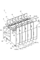
- FIG. 1 is a perspective view showing a battery module according to an embodiment of the present invention.
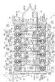
- FIG. 2 is a plan view of the battery module shown in FIG.
- the battery module 1 includes an array body 2 in which a plurality of battery cells 11 are arrayed, and a restraining member that applies a restraining load to the array body 2 in the array direction of the battery cells 11. 3 and an elastic body 4 interposed between the array body 2 and the restraining member 3.
- the array 2 is composed of, for example, a plurality (seven in this case) of battery cells 11 (11A to 11G toward the elastic body 4).
- a heat transfer plate (not shown) is interposed between the battery cells 11 and 11.
- the battery cell 11 is a nonaqueous electrolyte secondary battery such as a lithium ion secondary battery.
- the battery cell 11 is formed by housing an electrode assembly in a hollow case 12 having a substantially rectangular parallelepiped shape, for example.
- a pair of electrode terminals 17, 17 are provided on the top surface of the case 12 so as to be separated from each other. As shown in FIG.
- one of the electrode terminals 17 is a positive terminal 15 connected to the positive electrode of the electrode assembly, and the other of the electrode terminals 17 is a negative terminal 16 connected to the negative electrode of the electrode assembly. It has become.
- the adjacent battery cells 11 and 11 are arranged in such a manner that the positive electrode terminal 15 and the negative electrode terminal 16 are adjacent to each other, and the adjacent positive electrode terminal 15 and the negative electrode terminal 16 are connected by the bus bar member 18 so as to be electrically connected in series. It is connected to the.
- a battery holder 21 is attached to the battery cell 11.
- the battery holder 21 has a frame body 22 that is integrally formed of, for example, resin.
- the frame body 22 is fitted into the case 12 so as to be along each side surface of the side surface of the case 12 of the battery cell 11 excluding the side surface in the arrangement direction of the battery cells 11.
- the restraining member 3 includes, for example, a pair of end plates 31 and a fastening member 32 that fastens the end plates 31 together.
- the end plate 31 is formed of a metal such as iron, for example, and has a substantially rectangular plate shape having an area larger than the area when the battery cell 11 is viewed from the arrangement direction.
- the end plate 31 is disposed at both ends of the array body 2 and the elastic body 4 in the array direction, with the outer edge portion projecting outward from the outer edge portion of the battery cell 11.
- a bracket 35 is attached to the end plate 31.
- the battery module 1 is firmly fixed to a wall portion such as a housing via the bracket 35.
- the fastening member 32 includes, for example, a long bolt 33 and a nut 34 (see FIG. 2) screwed to the bolt.
- the bolt 33 is inserted through the end plate 31 at an outer edge portion of the end plate 31, for example.
- the nut 34 is screwed onto the both ends of each bolt 33 from the outside of the end plate 31, whereby the battery cell 11, the elastic body 4, and the heat transfer plate are sandwiched and unitized and a restraining load is applied.
- the elastic body 4 is a member used for the purpose of preventing damage to the restraint parts in addition to preventing damage to the battery cell 11 due to restraint load, and is formed in a rectangular plate shape by, for example, urethane rubber sponge.
- the elastic body 4 is disposed at one end of the array body 2 in the array direction of the battery cells 11. Examples of the material for forming the elastic body 4 include ethylene propylene diene rubber (EPDM), chloroprene rubber, and silicon rubber.
- EPDM ethylene propylene diene rubber
- chloroprene rubber chloroprene rubber
- silicon rubber silicon rubber.
- the elastic body 4 is not limited to rubber and may be a spring material or the like.
- a plurality of harnesses 41 used for voltage detection of the battery cell 11 are assembled to the battery module 1 having the above-described configuration.
- the plurality of harnesses 41 are wired by the binding member 42 and wired along the arrangement direction of the battery cells 11 in a state where the harness bundle 43 is formed.
- the pair of harness bundles 43 and 43 are connected to the battery from the elastic body 4 side so as to follow each of the row of one electrode terminal 17 of the battery cell 11 and the row of the other electrode terminal 17 of the battery cell 11. It is drawn into the cell 11 side.
- the base ends of the harness bundles 43 and 43 are joined together outside the battery module 1 while being covered with the covering member 44, and are electrically connected to, for example, a voltmeter (not shown) disposed above the battery module 1.
- a voltmeter not shown
- the harness 41 is branched at the tip of the covering member 44 and the binding member 42.
- connection terminals 45 (45A to 45H) are respectively provided at the ends of the branching harness 41, and the connection terminals 45 are connected to the electrode terminals 17 of the predetermined battery cells 11.
- the harness 41 and the battery cell 11 are electrically connected.
- the binding member 42 is configured by, for example, a resin tape or a resin tube.
- the length L of the binding member 42 can be set to an arbitrary length within a range that does not hinder the arrangement of the harness 41 branched from the other binding members 42.
- each of the harnesses 41 bound by the binding member 42 is provided with a mark 47 indicating a binding position (position of the leading end of the binding member 42) 46 by the binding member 42.
- a resin tape or a resin tube may be used, and the thing by application
- the harness 41 of the present embodiment is provided with two binding members 42 at a constant interval from the covering member 44, as shown in FIG.
- the covering member 44 that bundles the proximal ends of the harness bundles 43 and 43 also has a function as the binding member 42.
- the harness 41A branched from the binding member 42A on the front end side is connected to the positive terminal 15A of the battery cell 11A, and the harness 41B branched from the binding member A is connected to the negative terminal 16B of the battery cell 11B. It is connected.
- harness 41C branched from the binding member 42B on the base end side is connected to the negative electrode terminal 16D of the battery cell 11D
- harness 41D branched from the covering member 44 is connected to the negative electrode terminal 16F of the battery cell 11F.
- the harness 41E branched from the binding member 42C on the distal end side is connected to the negative electrode terminal 16A of the battery cell 11A
- the harness 41F branched similarly from the binding member 42C is connected to the negative electrode terminal of the battery cell 11C. 16C.
- the harness 41G branched from the binding member 42D on the proximal end side is connected to the negative electrode terminal 16E of the battery cell 11E
- the harness 41H branched from the covering member 44 is connected to the negative electrode terminal 16G of the battery cell 11G.
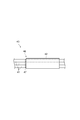
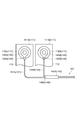
- FIG. 4 is a schematic diagram illustrating a state of the harness branched from the binding member.
- a harness 41A connected to the positive electrode terminal 15A of the battery cell 11A and a harness 41B connected to the negative electrode terminal 16B of the battery cell 11B are shown.
- the binding position 46A of the harnesses 41A and 41B by the binding member 42A is more elastic than the connection position 48B between the negative terminal 16B of the battery cell 11B and the connection terminal 45B of the harness 41B.
- the binding position 46A of the harnesses 41A and 41B by the binding member 42A is a line segment connecting the line segment R1 along the extending direction of the harness bundle 43 and the centers of the electrode terminals 17 and 17 of the battery cell 11. It is located on the elastic body 4 side with a predetermined interval W1 with respect to the intersection P where R2 intersects.
- the harness 41B branched from the binding member 42A is bent between the binding position 46A by the binding member 42A and the connection position 48B.
- the predetermined interval W1 is set as appropriate according to the thickness of the case 12 of the battery cell 11, the type of the harness 41, and the like, but it is preferable to consider the expansion amount of the battery cell 11. That is, the binding position 46A by the binding member 42A is preferably located closer to the elastic body 4 than the connection position 48B between the negative electrode terminal 16B and the connection terminal 45B when the latest battery cell 11B is expanded (FIG. 5). reference).
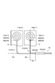
- FIG. 5 is a diagram showing the operational effects of the harnesses 41A and 41B shown in FIG.
- the elastic body 4 is disposed at one end (on the battery cell 11G side) of the array body 2 in the array direction of the battery cells 11. For this reason, when expansion
- the connection position 48A between the positive electrode terminal 15A and the connection terminal 45A of the battery cell 11A directly restrained by the end plate 31 hardly changes, but the negative electrode terminal 16B and the connection terminal 45B of the battery cell 11B are not changed. As shown in FIG. 5, the connection position 48B moves from the initial position to the elastic body 4 side.
- the binding position 46A of the harnesses 41A and 41B by the binding member 42A is connected to the negative terminal 16B and the connection terminal 45 when the latest battery cell 11B is expanded.
- the harness 41B branching from the binding member 42A is bent between the binding position 46A and the connection position 48B, and is located closer to the elastic body 4 than the position 48B. Therefore, even when the connection position 48B moves from the initial position to the elastic body 4 side, the length of the harness 41B branched from the binding member 42A is prevented from being insufficient, and the bending of the harness 41B is maintained. The Since the bending of the harness 41B is maintained, it is possible to suppress an excessive load such as a tension from being applied to the harness 41B.
- FIG. 6 is an enlarged schematic view of the main part showing the assembled state of the harness branched from the binding member in the battery module according to the comparative example.
- the binding position 146A of the harnesses 141A and 141B by the binding member 142A and the connection position 148B of the negative electrode terminal 116B (electrode terminal 117) of the battery cell 111B and the connection terminal 145B of the harness 141B Are in a complete state.
- the binding positions 146A of the harnesses 141A and 141B by the binding member 142A are the line segment R1 along the extending direction of the harness bundle 143, the center of the negative electrode terminal 116B of the battery cell 111B, and the positive electrode terminal 115B (electrodes). It substantially coincides with the intersection P where the line segment R2 connecting the center of the terminal 117) intersects.
- the length of the harness 141B branched from the binding position 146A substantially matches the distance from the binding position 146A to the connection position 148B.
- the length of the harness 141B is insufficient with respect to the movement of the connection position 148B when the battery cell 111 is expanded. If the length of the harness 141B is insufficient, as shown in FIG. 7, a load due to tension is applied to the harness 141B, and there is a possibility that a malfunction such as disconnection may occur in the harness 141B. Therefore, as shown in FIG. 4, it is suitable to suppress a defect such as a disconnection by giving the harness 141B branched from the binding member 142A.
- the harnesses 41B, 41C, 41F, 41G, and 41H in that the harness 41 branched from the binding member 42 is bent.
- the connection positions of the electrode terminals 17 and the connection terminals 45 when the array body 2 expands in one direction toward the elastic body 4 as in the battery cell 11B. 48 moves from the initial position to the elastic body 4 side. Accordingly, by causing the harness 41 branched from the binding member 42 to bend, it is possible to suppress the occurrence of problems such as disconnection.
- the amount by which the connection position 48 between the electrode terminal 17 and the connection terminal 45 moves with respect to the binding position 46 of the harness 41 is the battery cell 11 located on the elastic body 4 side.
- the expansion amount of each battery cell 11 is added and becomes larger. Therefore, it is preferable that the bending amount of the harness 41 branched from the binding member 42 increases as the battery cell 11 to which the harness 41 is connected is located on the elastic body 4 side. Thereby, even if the connection position 48 between the electrode terminal 17 and the connection terminal 45 is moved with respect to the binding position 46 due to the expansion of the battery cell 11, the length of the harness 41 branched at the distal end side of the binding member 42. Can be prevented more reliably.
- the distance between the binding position 46C of the harness 41F by the binding member 42C and the intersection P between the line segment R1 and the line segment R2 is set to W2, in order from the battery cell 11A side.
- the distance between the binding position 46B of the harness 41C by the binding member 42B and the intersection P between the line segment R1 and the line segment R2 is W3, the binding position 46D of the harness 41G by the binding member 42D, the line segment R1, and the line segment R2
- the distance between the crossing point P and the intersection point P is W4
- the binding position 46E of the harness 41D by the covering member 44 and the interval between the intersection point P between the line segment R1 and the line segment R2 is W5
- the harness 41H by the covering member 44 is
- the interval between the binding position 46F and the intersection P between the line segment R1 and the line segment R2 is W6, the relationship of W1 ⁇ W2 ⁇ W3 ⁇ W4 ⁇ W5 ⁇ W6 is satisfied.
- the mark 47 which shows the binding position 46 by the binding member 42 is provided in each harness 41 (refer FIG. 3).
- the binding position 46 of the harness 41 by the binding member 42 can be easily grasped. Therefore, the variation of the binding range for each harness 41 can be suppressed, and the length of the harness 41 branched at the distal end side of the binding member 42 can be more reliably ensured.
- the present invention is not limited to the above embodiment.
- the harness used for the voltage detection of the battery cell 11 was shown as the harness 41, the use of a harness is not limited to this.
- the harness 41 branched from the binding member 42 is bent by shifting the binding position 46 of the harness 41 by the binding member 42 from the intersection P of the line segment R1 and the line segment R2 toward the elastic body 4 side. Although it has given, how to give bending to harness 41 is not limited to this.
- the binding position 46A of the harnesses 41A and 41B by the binding member 42A is made to substantially coincide with the intersection P between the line segment R1 and the line segment R2, while the length of the harness 41B branched from the binding position 46A is set.
- the harness 41B may be bent by making it longer than the distance from the binding position 46A to the connection position 48B. Even in such a configuration, the length of the harness 41B branched from the binding member 42A is prevented from being insufficient, and even if the battery cell 11B expands, an excessive load such as tension is applied to the harness 41B. Can be suppressed. Therefore, occurrence of problems such as disconnection can be suppressed.
- SYMBOLS 1 Battery module, 2 ... Array, 3 ... Restraint member, 11 ... Battery cell, 17 ... Electrode terminal, 41 (41A-41H) ... Harness, 42 (42A-42D) ... Bundling member, 43 ... Harness bundle, 44 ... coating member (bundling member), 45 (45A to 45H) ... connection terminal, 46 (46A to 46F) ... binding position, 47 ... mark, 48 (48A to 48H) ... connection position.
Landscapes
- Chemical & Material Sciences (AREA)
- Chemical Kinetics & Catalysis (AREA)
- Electrochemistry (AREA)
- General Chemical & Material Sciences (AREA)
- Engineering & Computer Science (AREA)
- Materials Engineering (AREA)
- Manufacturing & Machinery (AREA)
- Battery Mounting, Suspending (AREA)
- Connection Of Batteries Or Terminals (AREA)
- Secondary Cells (AREA)
Priority Applications (3)
| Application Number | Priority Date | Filing Date | Title |
|---|---|---|---|
| US15/511,539 US10461300B2 (en) | 2014-09-19 | 2015-05-27 | Battery Module |
| DE112015004259.8T DE112015004259B4 (de) | 2014-09-19 | 2015-05-27 | Batteriemodul |
| CN201580049641.9A CN107078262B (zh) | 2014-09-19 | 2015-05-27 | 电池模块 |
Applications Claiming Priority (2)
| Application Number | Priority Date | Filing Date | Title |
|---|---|---|---|
| JP2014-190976 | 2014-09-19 | ||
| JP2014190976A JP6379918B2 (ja) | 2014-09-19 | 2014-09-19 | 電池モジュール |
Publications (1)
| Publication Number | Publication Date |
|---|---|
| WO2016042848A1 true WO2016042848A1 (ja) | 2016-03-24 |
Family
ID=55532893
Family Applications (1)
| Application Number | Title | Priority Date | Filing Date |
|---|---|---|---|
| PCT/JP2015/065273 Ceased WO2016042848A1 (ja) | 2014-09-19 | 2015-05-27 | 電池モジュール |
Country Status (5)
| Country | Link |
|---|---|
| US (1) | US10461300B2 (enExample) |
| JP (1) | JP6379918B2 (enExample) |
| CN (1) | CN107078262B (enExample) |
| DE (1) | DE112015004259B4 (enExample) |
| WO (1) | WO2016042848A1 (enExample) |
Families Citing this family (4)
| Publication number | Priority date | Publication date | Assignee | Title |
|---|---|---|---|---|
| JP6384294B2 (ja) * | 2014-11-28 | 2018-09-05 | 株式会社豊田自動織機 | 電池モジュール |
| JP6565751B2 (ja) * | 2016-03-15 | 2019-08-28 | 株式会社豊田自動織機 | 電池モジュール |
| JP6780374B2 (ja) * | 2016-08-30 | 2020-11-04 | 株式会社豊田自動織機 | 電池モジュール |
| CN108493506B (zh) * | 2018-05-07 | 2024-10-29 | 江西鼎杰科技有限公司 | 一种电池包结构 |
Citations (5)
| Publication number | Priority date | Publication date | Assignee | Title |
|---|---|---|---|---|
| JP2010170884A (ja) * | 2009-01-23 | 2010-08-05 | Yazaki Corp | バスバモジュール、及び、バスバモジュールの組み立て方法 |
| JP2010287516A (ja) * | 2009-06-15 | 2010-12-24 | Nissan Motor Co Ltd | コネクタモジュール |
| JP2011070846A (ja) * | 2009-09-24 | 2011-04-07 | Yazaki Corp | 電線配索装置 |
| WO2011132671A1 (ja) * | 2010-04-22 | 2011-10-27 | 矢崎総業株式会社 | バッテリ接続プレート |
| JP2013098032A (ja) * | 2011-11-01 | 2013-05-20 | Auto Network Gijutsu Kenkyusho:Kk | 電圧検知端子の接続構造 |
Family Cites Families (7)
| Publication number | Priority date | Publication date | Assignee | Title |
|---|---|---|---|---|
| JP5256634B2 (ja) | 2007-03-26 | 2013-08-07 | 日産自動車株式会社 | 組電池、および組電池用コネクタモジュール |
| JP5813302B2 (ja) | 2009-09-07 | 2015-11-17 | 矢崎総業株式会社 | バスバモジュール、及び、このバスバモジュールを備えた電源装置 |
| JP5530690B2 (ja) * | 2009-09-24 | 2014-06-25 | 矢崎総業株式会社 | ワイヤハーネス |
| US9028996B2 (en) | 2011-09-29 | 2015-05-12 | Lithium Energy Japan | Battery pack |
| JP5830339B2 (ja) * | 2011-10-11 | 2015-12-09 | 矢崎総業株式会社 | 編組及びワイヤハーネス |
| JP2013055069A (ja) | 2012-12-19 | 2013-03-21 | Sanyo Electric Co Ltd | 組電池の組立方法 |
| CN203631621U (zh) * | 2013-12-05 | 2014-06-04 | 宁德时代新能源科技有限公司 | 电池模组 |
-
2014
- 2014-09-19 JP JP2014190976A patent/JP6379918B2/ja not_active Expired - Fee Related
-
2015
- 2015-05-27 CN CN201580049641.9A patent/CN107078262B/zh not_active Expired - Fee Related
- 2015-05-27 DE DE112015004259.8T patent/DE112015004259B4/de not_active Expired - Fee Related
- 2015-05-27 WO PCT/JP2015/065273 patent/WO2016042848A1/ja not_active Ceased
- 2015-05-27 US US15/511,539 patent/US10461300B2/en not_active Expired - Fee Related
Patent Citations (5)
| Publication number | Priority date | Publication date | Assignee | Title |
|---|---|---|---|---|
| JP2010170884A (ja) * | 2009-01-23 | 2010-08-05 | Yazaki Corp | バスバモジュール、及び、バスバモジュールの組み立て方法 |
| JP2010287516A (ja) * | 2009-06-15 | 2010-12-24 | Nissan Motor Co Ltd | コネクタモジュール |
| JP2011070846A (ja) * | 2009-09-24 | 2011-04-07 | Yazaki Corp | 電線配索装置 |
| WO2011132671A1 (ja) * | 2010-04-22 | 2011-10-27 | 矢崎総業株式会社 | バッテリ接続プレート |
| JP2013098032A (ja) * | 2011-11-01 | 2013-05-20 | Auto Network Gijutsu Kenkyusho:Kk | 電圧検知端子の接続構造 |
Also Published As
| Publication number | Publication date |
|---|---|
| US20170288197A1 (en) | 2017-10-05 |
| JP2016062800A (ja) | 2016-04-25 |
| US10461300B2 (en) | 2019-10-29 |
| DE112015004259T5 (de) | 2017-06-14 |
| JP6379918B2 (ja) | 2018-08-29 |
| CN107078262A (zh) | 2017-08-18 |
| CN107078262B (zh) | 2019-06-28 |
| DE112015004259B4 (de) | 2022-01-27 |
Similar Documents
| Publication | Publication Date | Title |
|---|---|---|
| EP2109906B1 (en) | Buss bar for batteries | |
| US10135101B2 (en) | Power storage module | |
| KR101280796B1 (ko) | 2차 전지용 버스바 및 2차 전지 모듈 | |
| US9178203B2 (en) | Battery module with a flexible bus | |
| JP6379918B2 (ja) | 電池モジュール | |
| JP2020205175A (ja) | バスバモジュール | |
| JP5407576B2 (ja) | コネクタモジュール | |
| JP2015049932A (ja) | 電池パックの電池内配線モジュール | |
| JP6384294B2 (ja) | 電池モジュール | |
| CN107819098B (zh) | 电池模块以及电池组 | |
| JP6613791B2 (ja) | 電池パック | |
| CN112002866A (zh) | 电池布线模块 | |
| US20250149748A1 (en) | Connection module set, electrode connection member set, and battery pack | |
| JP7393732B2 (ja) | 蓄電装置 | |
| CN108780870B (zh) | 电池模块 | |
| JP6610007B2 (ja) | 電池パック | |
| JP7082521B2 (ja) | 蓄電装置 | |
| JP6094856B2 (ja) | 蓄電装置及び車両並びに接続端子 | |
| JP2017097980A (ja) | 配線モジュール | |
| JP7205408B2 (ja) | ワイヤハーネス用プロテクタ、及びプロテクタ付ワイヤハーネス |
Legal Events
| Date | Code | Title | Description |
|---|---|---|---|
| 121 | Ep: the epo has been informed by wipo that ep was designated in this application |
Ref document number: 15841643 Country of ref document: EP Kind code of ref document: A1 |
|
| WWE | Wipo information: entry into national phase |
Ref document number: 15511539 Country of ref document: US |
|
| WWE | Wipo information: entry into national phase |
Ref document number: 112015004259 Country of ref document: DE |
|
| 122 | Ep: pct application non-entry in european phase |
Ref document number: 15841643 Country of ref document: EP Kind code of ref document: A1 |