WO2016042848A1 - Battery module - Google Patents
Battery module Download PDFInfo
- Publication number
- WO2016042848A1 WO2016042848A1 PCT/JP2015/065273 JP2015065273W WO2016042848A1 WO 2016042848 A1 WO2016042848 A1 WO 2016042848A1 JP 2015065273 W JP2015065273 W JP 2015065273W WO 2016042848 A1 WO2016042848 A1 WO 2016042848A1
- Authority
- WO
- WIPO (PCT)
- Prior art keywords
- harness
- binding
- battery cell
- binding member
- battery
- Prior art date
Links
Images


Classifications
-
- H—ELECTRICITY
- H01—ELECTRIC ELEMENTS
- H01M—PROCESSES OR MEANS, e.g. BATTERIES, FOR THE DIRECT CONVERSION OF CHEMICAL ENERGY INTO ELECTRICAL ENERGY
- H01M50/00—Constructional details or processes of manufacture of the non-active parts of electrochemical cells other than fuel cells, e.g. hybrid cells
- H01M50/50—Current conducting connections for cells or batteries
- H01M50/502—Interconnectors for connecting terminals of adjacent batteries; Interconnectors for connecting cells outside a battery casing
-
- H—ELECTRICITY
- H01—ELECTRIC ELEMENTS
- H01M—PROCESSES OR MEANS, e.g. BATTERIES, FOR THE DIRECT CONVERSION OF CHEMICAL ENERGY INTO ELECTRICAL ENERGY
- H01M10/00—Secondary cells; Manufacture thereof
- H01M10/05—Accumulators with non-aqueous electrolyte
- H01M10/052—Li-accumulators
- H01M10/0525—Rocking-chair batteries, i.e. batteries with lithium insertion or intercalation in both electrodes; Lithium-ion batteries
-
- H—ELECTRICITY
- H01—ELECTRIC ELEMENTS
- H01M—PROCESSES OR MEANS, e.g. BATTERIES, FOR THE DIRECT CONVERSION OF CHEMICAL ENERGY INTO ELECTRICAL ENERGY
- H01M50/00—Constructional details or processes of manufacture of the non-active parts of electrochemical cells other than fuel cells, e.g. hybrid cells
- H01M50/20—Mountings; Secondary casings or frames; Racks, modules or packs; Suspension devices; Shock absorbers; Transport or carrying devices; Holders
- H01M50/256—Carrying devices, e.g. belts
-
- H—ELECTRICITY
- H01—ELECTRIC ELEMENTS
- H01M—PROCESSES OR MEANS, e.g. BATTERIES, FOR THE DIRECT CONVERSION OF CHEMICAL ENERGY INTO ELECTRICAL ENERGY
- H01M50/00—Constructional details or processes of manufacture of the non-active parts of electrochemical cells other than fuel cells, e.g. hybrid cells
- H01M50/10—Primary casings, jackets or wrappings of a single cell or a single battery
- H01M50/172—Arrangements of electric connectors penetrating the casing
- H01M50/174—Arrangements of electric connectors penetrating the casing adapted for the shape of the cells
- H01M50/176—Arrangements of electric connectors penetrating the casing adapted for the shape of the cells for prismatic or rectangular cells
-
- H—ELECTRICITY
- H01—ELECTRIC ELEMENTS
- H01M—PROCESSES OR MEANS, e.g. BATTERIES, FOR THE DIRECT CONVERSION OF CHEMICAL ENERGY INTO ELECTRICAL ENERGY
- H01M50/00—Constructional details or processes of manufacture of the non-active parts of electrochemical cells other than fuel cells, e.g. hybrid cells
- H01M50/20—Mountings; Secondary casings or frames; Racks, modules or packs; Suspension devices; Shock absorbers; Transport or carrying devices; Holders
- H01M50/204—Racks, modules or packs for multiple batteries or multiple cells
- H01M50/207—Racks, modules or packs for multiple batteries or multiple cells characterised by their shape
- H01M50/209—Racks, modules or packs for multiple batteries or multiple cells characterised by their shape adapted for prismatic or rectangular cells
-
- H—ELECTRICITY
- H01—ELECTRIC ELEMENTS
- H01M—PROCESSES OR MEANS, e.g. BATTERIES, FOR THE DIRECT CONVERSION OF CHEMICAL ENERGY INTO ELECTRICAL ENERGY
- H01M50/00—Constructional details or processes of manufacture of the non-active parts of electrochemical cells other than fuel cells, e.g. hybrid cells
- H01M50/50—Current conducting connections for cells or batteries
- H01M50/502—Interconnectors for connecting terminals of adjacent batteries; Interconnectors for connecting cells outside a battery casing
- H01M50/507—Interconnectors for connecting terminals of adjacent batteries; Interconnectors for connecting cells outside a battery casing comprising an arrangement of two or more busbars within a container structure, e.g. busbar modules
-
- H—ELECTRICITY
- H01—ELECTRIC ELEMENTS
- H01M—PROCESSES OR MEANS, e.g. BATTERIES, FOR THE DIRECT CONVERSION OF CHEMICAL ENERGY INTO ELECTRICAL ENERGY
- H01M50/00—Constructional details or processes of manufacture of the non-active parts of electrochemical cells other than fuel cells, e.g. hybrid cells
- H01M50/50—Current conducting connections for cells or batteries
- H01M50/531—Electrode connections inside a battery casing
-
- H—ELECTRICITY
- H01—ELECTRIC ELEMENTS
- H01M—PROCESSES OR MEANS, e.g. BATTERIES, FOR THE DIRECT CONVERSION OF CHEMICAL ENERGY INTO ELECTRICAL ENERGY
- H01M50/00—Constructional details or processes of manufacture of the non-active parts of electrochemical cells other than fuel cells, e.g. hybrid cells
- H01M50/50—Current conducting connections for cells or batteries
- H01M50/543—Terminals
- H01M50/547—Terminals characterised by the disposition of the terminals on the cells
- H01M50/55—Terminals characterised by the disposition of the terminals on the cells on the same side of the cell
-
- H—ELECTRICITY
- H01—ELECTRIC ELEMENTS
- H01M—PROCESSES OR MEANS, e.g. BATTERIES, FOR THE DIRECT CONVERSION OF CHEMICAL ENERGY INTO ELECTRICAL ENERGY
- H01M50/00—Constructional details or processes of manufacture of the non-active parts of electrochemical cells other than fuel cells, e.g. hybrid cells
- H01M50/50—Current conducting connections for cells or batteries
- H01M50/543—Terminals
- H01M50/552—Terminals characterised by their shape
- H01M50/553—Terminals adapted for prismatic, pouch or rectangular cells
-
- Y—GENERAL TAGGING OF NEW TECHNOLOGICAL DEVELOPMENTS; GENERAL TAGGING OF CROSS-SECTIONAL TECHNOLOGIES SPANNING OVER SEVERAL SECTIONS OF THE IPC; TECHNICAL SUBJECTS COVERED BY FORMER USPC CROSS-REFERENCE ART COLLECTIONS [XRACs] AND DIGESTS
- Y02—TECHNOLOGIES OR APPLICATIONS FOR MITIGATION OR ADAPTATION AGAINST CLIMATE CHANGE
- Y02E—REDUCTION OF GREENHOUSE GAS [GHG] EMISSIONS, RELATED TO ENERGY GENERATION, TRANSMISSION OR DISTRIBUTION
- Y02E60/00—Enabling technologies; Technologies with a potential or indirect contribution to GHG emissions mitigation
- Y02E60/10—Energy storage using batteries
Definitions
- the present invention relates to a battery module.
- a battery module in which a plurality of battery cells such as lithium ion secondary batteries are arranged is known.
- the battery cell array is sandwiched by a restraining tool such as a metal plate and restrained by a constant load, thereby suppressing fluctuations in characteristics such as internal resistance in the battery cell.
- a restraining tool such as a metal plate
- a constant load thereby suppressing fluctuations in characteristics such as internal resistance in the battery cell.
- a metal band having bent portions at both ends is fixed to an end plate, and the battery block is constrained in the stacking direction by the end plate.
- an elastic body such as rubber may be interposed between the array body and the end plate of the restraining member for the purpose of preventing damage to the restraining member due to expansion of the battery cell.
- a harness used for voltage detection of each battery cell may be assembled to the battery module.
- a connector having a voltage detection terminal is held by a holding member, and the holding member is attached to a battery group, so that the connector is electrically connected to the electrode terminals of the battery cells. Connected to.
- the proximal ends of the plurality of harnesses are bundled with a bundling member and assembled to the battery module in a harness bundle state. Further, when connecting the connection terminal at the tip of the harness to the electrode terminal of the battery cell, the lengths of the harnesses branched at the tip end side of the binding member may be different from each other so that the connection destination is not mistaken.
- the present invention has been made to solve the above problems, and an object of the present invention is to provide a battery module capable of suppressing a load applied to a harness even when the battery cell is expanded.
- a battery module includes an array formed by arraying a plurality of battery cells, a battery cell in the array extending along the array direction, and a connection at the tip.
- a plurality of harnesses each having a terminal connected to an electrode terminal of a predetermined battery cell; and a binding member that binds the plurality of harnesses to form a harness bundle.
- the binding position of the harness by the binding member, the electrode terminal, and the connection terminal The harness that branches off from the binding member has a deflection between the connection position and the connection position.
- the harness branched from the binding member is bent between the binding position of the harness by the binding member and the connection position of the electrode terminal and the connection terminal. For this reason, even if the battery cell expands and the connection position between the battery cell electrode terminal and the harness connection terminal moves relative to the binding position of the harness, the harness branching on the leading end side of the binding member It is possible to prevent the length from being insufficient. Therefore, it can suppress that a load is applied to a harness and generation
- the battery module further includes an elastic body disposed at one array end of the battery cells in the array body, and a restraining member that restrains the array body in the array direction via the elastic body, and the plurality of harnesses include:
- the binding position of the harness by the binding member may be located closer to the elastic body than the connection position between the electrode terminal and the connection terminal.
- the connection position between the electrode terminal and the connection terminal when the battery cell is expanded moves in one direction from the initial position to the elastic body side. Therefore, by positioning the binding position of the harness by the binding member closer to the elastic body than the connection position between the electrode terminal and the connection terminal, the connection position between the electrode terminal of the battery cell and the connection terminal of the harness is relative to the binding position of the harness. Even if it moves, it can prevent suitably that the length of the harness which branches on the front end side of a binding member runs short.
- the binding position of the harness by the binding member may be located closer to the elastic body than the connection position between the electrode terminal and the connection terminal when the connection destination battery cell is expanded.
- the bending amount of the harness branched from the binding member may be increased as the battery cell to which the harness is connected is positioned on the elastic body side.
- the amount of movement of the connection position between the electrode terminal of the battery cell and the connection terminal of the harness relative to the binding position of the harness becomes larger as the battery cell is positioned on the elastic body side. Therefore, by increasing the bending amount of the harness branched from the binding member as the battery cell to which the harness is connected is located on the elastic body side, the connection position between the electrode terminal of the battery cell and the connection terminal of the harness is increased. Even when the harness moves with respect to the binding position of the harness, it is possible to more reliably prevent the harness that branches off at the leading end side of the binding member from becoming insufficient.
- each of the harnesses may be provided with a mark indicating a binding position by the binding member.
- the binding position of the harness by the binding member can be easily grasped. Therefore, variation in the binding range for each harness can be suppressed, and the length of the harness that branches off at the front end side of the binding member can be more reliably ensured.
- the harness may be a harness used for detecting the voltage of the battery cell.
- the above-described harness arrangement is suitable for the harness arrangement used for voltage detection of the battery cell.
- the battery module according to the present invention can suppress the load applied to the harness even when the battery cell expands.
- FIG. 5 is an enlarged schematic view of a main part showing a state when the battery cell of the harness shown in FIG. 4 is expanded.
- FIG. 5 is a principal part expansion schematic diagram which shows the assembly
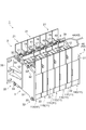
- FIG. 1 is a perspective view showing a battery module according to an embodiment of the present invention.
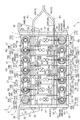
- FIG. 2 is a plan view of the battery module shown in FIG.
- the battery module 1 includes an array body 2 in which a plurality of battery cells 11 are arrayed, and a restraining member that applies a restraining load to the array body 2 in the array direction of the battery cells 11. 3 and an elastic body 4 interposed between the array body 2 and the restraining member 3.
- the array 2 is composed of, for example, a plurality (seven in this case) of battery cells 11 (11A to 11G toward the elastic body 4).
- a heat transfer plate (not shown) is interposed between the battery cells 11 and 11.
- the battery cell 11 is a nonaqueous electrolyte secondary battery such as a lithium ion secondary battery.
- the battery cell 11 is formed by housing an electrode assembly in a hollow case 12 having a substantially rectangular parallelepiped shape, for example.
- a pair of electrode terminals 17, 17 are provided on the top surface of the case 12 so as to be separated from each other. As shown in FIG.
- one of the electrode terminals 17 is a positive terminal 15 connected to the positive electrode of the electrode assembly, and the other of the electrode terminals 17 is a negative terminal 16 connected to the negative electrode of the electrode assembly. It has become.
- the adjacent battery cells 11 and 11 are arranged in such a manner that the positive electrode terminal 15 and the negative electrode terminal 16 are adjacent to each other, and the adjacent positive electrode terminal 15 and the negative electrode terminal 16 are connected by the bus bar member 18 so as to be electrically connected in series. It is connected to the.
- a battery holder 21 is attached to the battery cell 11.
- the battery holder 21 has a frame body 22 that is integrally formed of, for example, resin.
- the frame body 22 is fitted into the case 12 so as to be along each side surface of the side surface of the case 12 of the battery cell 11 excluding the side surface in the arrangement direction of the battery cells 11.
- the restraining member 3 includes, for example, a pair of end plates 31 and a fastening member 32 that fastens the end plates 31 together.
- the end plate 31 is formed of a metal such as iron, for example, and has a substantially rectangular plate shape having an area larger than the area when the battery cell 11 is viewed from the arrangement direction.
- the end plate 31 is disposed at both ends of the array body 2 and the elastic body 4 in the array direction, with the outer edge portion projecting outward from the outer edge portion of the battery cell 11.
- a bracket 35 is attached to the end plate 31.
- the battery module 1 is firmly fixed to a wall portion such as a housing via the bracket 35.
- the fastening member 32 includes, for example, a long bolt 33 and a nut 34 (see FIG. 2) screwed to the bolt.
- the bolt 33 is inserted through the end plate 31 at an outer edge portion of the end plate 31, for example.
- the nut 34 is screwed onto the both ends of each bolt 33 from the outside of the end plate 31, whereby the battery cell 11, the elastic body 4, and the heat transfer plate are sandwiched and unitized and a restraining load is applied.
- the elastic body 4 is a member used for the purpose of preventing damage to the restraint parts in addition to preventing damage to the battery cell 11 due to restraint load, and is formed in a rectangular plate shape by, for example, urethane rubber sponge.
- the elastic body 4 is disposed at one end of the array body 2 in the array direction of the battery cells 11. Examples of the material for forming the elastic body 4 include ethylene propylene diene rubber (EPDM), chloroprene rubber, and silicon rubber.
- EPDM ethylene propylene diene rubber
- chloroprene rubber chloroprene rubber
- silicon rubber silicon rubber.
- the elastic body 4 is not limited to rubber and may be a spring material or the like.
- a plurality of harnesses 41 used for voltage detection of the battery cell 11 are assembled to the battery module 1 having the above-described configuration.
- the plurality of harnesses 41 are wired by the binding member 42 and wired along the arrangement direction of the battery cells 11 in a state where the harness bundle 43 is formed.
- the pair of harness bundles 43 and 43 are connected to the battery from the elastic body 4 side so as to follow each of the row of one electrode terminal 17 of the battery cell 11 and the row of the other electrode terminal 17 of the battery cell 11. It is drawn into the cell 11 side.
- the base ends of the harness bundles 43 and 43 are joined together outside the battery module 1 while being covered with the covering member 44, and are electrically connected to, for example, a voltmeter (not shown) disposed above the battery module 1.
- a voltmeter not shown
- the harness 41 is branched at the tip of the covering member 44 and the binding member 42.
- connection terminals 45 (45A to 45H) are respectively provided at the ends of the branching harness 41, and the connection terminals 45 are connected to the electrode terminals 17 of the predetermined battery cells 11.
- the harness 41 and the battery cell 11 are electrically connected.
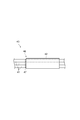
- the binding member 42 is configured by, for example, a resin tape or a resin tube.
- the length L of the binding member 42 can be set to an arbitrary length within a range that does not hinder the arrangement of the harness 41 branched from the other binding members 42.
- each of the harnesses 41 bound by the binding member 42 is provided with a mark 47 indicating a binding position (position of the leading end of the binding member 42) 46 by the binding member 42.
- a resin tape or a resin tube may be used, and the thing by application
- the harness 41 of the present embodiment is provided with two binding members 42 at a constant interval from the covering member 44, as shown in FIG.
- the covering member 44 that bundles the proximal ends of the harness bundles 43 and 43 also has a function as the binding member 42.
- the harness 41A branched from the binding member 42A on the front end side is connected to the positive terminal 15A of the battery cell 11A, and the harness 41B branched from the binding member A is connected to the negative terminal 16B of the battery cell 11B. It is connected.
- harness 41C branched from the binding member 42B on the base end side is connected to the negative electrode terminal 16D of the battery cell 11D
- harness 41D branched from the covering member 44 is connected to the negative electrode terminal 16F of the battery cell 11F.
- the harness 41E branched from the binding member 42C on the distal end side is connected to the negative electrode terminal 16A of the battery cell 11A
- the harness 41F branched similarly from the binding member 42C is connected to the negative electrode terminal of the battery cell 11C. 16C.
- the harness 41G branched from the binding member 42D on the proximal end side is connected to the negative electrode terminal 16E of the battery cell 11E
- the harness 41H branched from the covering member 44 is connected to the negative electrode terminal 16G of the battery cell 11G.
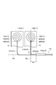
- FIG. 4 is a schematic diagram illustrating a state of the harness branched from the binding member.
- a harness 41A connected to the positive electrode terminal 15A of the battery cell 11A and a harness 41B connected to the negative electrode terminal 16B of the battery cell 11B are shown.
- the binding position 46A of the harnesses 41A and 41B by the binding member 42A is more elastic than the connection position 48B between the negative terminal 16B of the battery cell 11B and the connection terminal 45B of the harness 41B.
- the binding position 46A of the harnesses 41A and 41B by the binding member 42A is a line segment connecting the line segment R1 along the extending direction of the harness bundle 43 and the centers of the electrode terminals 17 and 17 of the battery cell 11. It is located on the elastic body 4 side with a predetermined interval W1 with respect to the intersection P where R2 intersects.
- the harness 41B branched from the binding member 42A is bent between the binding position 46A by the binding member 42A and the connection position 48B.
- the predetermined interval W1 is set as appropriate according to the thickness of the case 12 of the battery cell 11, the type of the harness 41, and the like, but it is preferable to consider the expansion amount of the battery cell 11. That is, the binding position 46A by the binding member 42A is preferably located closer to the elastic body 4 than the connection position 48B between the negative electrode terminal 16B and the connection terminal 45B when the latest battery cell 11B is expanded (FIG. 5). reference).
- FIG. 5 is a diagram showing the operational effects of the harnesses 41A and 41B shown in FIG.
- the elastic body 4 is disposed at one end (on the battery cell 11G side) of the array body 2 in the array direction of the battery cells 11. For this reason, when expansion
- the connection position 48A between the positive electrode terminal 15A and the connection terminal 45A of the battery cell 11A directly restrained by the end plate 31 hardly changes, but the negative electrode terminal 16B and the connection terminal 45B of the battery cell 11B are not changed. As shown in FIG. 5, the connection position 48B moves from the initial position to the elastic body 4 side.
- the binding position 46A of the harnesses 41A and 41B by the binding member 42A is connected to the negative terminal 16B and the connection terminal 45 when the latest battery cell 11B is expanded.
- the harness 41B branching from the binding member 42A is bent between the binding position 46A and the connection position 48B, and is located closer to the elastic body 4 than the position 48B. Therefore, even when the connection position 48B moves from the initial position to the elastic body 4 side, the length of the harness 41B branched from the binding member 42A is prevented from being insufficient, and the bending of the harness 41B is maintained. The Since the bending of the harness 41B is maintained, it is possible to suppress an excessive load such as a tension from being applied to the harness 41B.
- FIG. 6 is an enlarged schematic view of the main part showing the assembled state of the harness branched from the binding member in the battery module according to the comparative example.
- the binding position 146A of the harnesses 141A and 141B by the binding member 142A and the connection position 148B of the negative electrode terminal 116B (electrode terminal 117) of the battery cell 111B and the connection terminal 145B of the harness 141B Are in a complete state.
- the binding positions 146A of the harnesses 141A and 141B by the binding member 142A are the line segment R1 along the extending direction of the harness bundle 143, the center of the negative electrode terminal 116B of the battery cell 111B, and the positive electrode terminal 115B (electrodes). It substantially coincides with the intersection P where the line segment R2 connecting the center of the terminal 117) intersects.
- the length of the harness 141B branched from the binding position 146A substantially matches the distance from the binding position 146A to the connection position 148B.
- the length of the harness 141B is insufficient with respect to the movement of the connection position 148B when the battery cell 111 is expanded. If the length of the harness 141B is insufficient, as shown in FIG. 7, a load due to tension is applied to the harness 141B, and there is a possibility that a malfunction such as disconnection may occur in the harness 141B. Therefore, as shown in FIG. 4, it is suitable to suppress a defect such as a disconnection by giving the harness 141B branched from the binding member 142A.
- the harnesses 41B, 41C, 41F, 41G, and 41H in that the harness 41 branched from the binding member 42 is bent.
- the connection positions of the electrode terminals 17 and the connection terminals 45 when the array body 2 expands in one direction toward the elastic body 4 as in the battery cell 11B. 48 moves from the initial position to the elastic body 4 side. Accordingly, by causing the harness 41 branched from the binding member 42 to bend, it is possible to suppress the occurrence of problems such as disconnection.
- the amount by which the connection position 48 between the electrode terminal 17 and the connection terminal 45 moves with respect to the binding position 46 of the harness 41 is the battery cell 11 located on the elastic body 4 side.
- the expansion amount of each battery cell 11 is added and becomes larger. Therefore, it is preferable that the bending amount of the harness 41 branched from the binding member 42 increases as the battery cell 11 to which the harness 41 is connected is located on the elastic body 4 side. Thereby, even if the connection position 48 between the electrode terminal 17 and the connection terminal 45 is moved with respect to the binding position 46 due to the expansion of the battery cell 11, the length of the harness 41 branched at the distal end side of the binding member 42. Can be prevented more reliably.
- the distance between the binding position 46C of the harness 41F by the binding member 42C and the intersection P between the line segment R1 and the line segment R2 is set to W2, in order from the battery cell 11A side.
- the distance between the binding position 46B of the harness 41C by the binding member 42B and the intersection P between the line segment R1 and the line segment R2 is W3, the binding position 46D of the harness 41G by the binding member 42D, the line segment R1, and the line segment R2
- the distance between the crossing point P and the intersection point P is W4
- the binding position 46E of the harness 41D by the covering member 44 and the interval between the intersection point P between the line segment R1 and the line segment R2 is W5
- the harness 41H by the covering member 44 is
- the interval between the binding position 46F and the intersection P between the line segment R1 and the line segment R2 is W6, the relationship of W1 ⁇ W2 ⁇ W3 ⁇ W4 ⁇ W5 ⁇ W6 is satisfied.
- the mark 47 which shows the binding position 46 by the binding member 42 is provided in each harness 41 (refer FIG. 3).
- the binding position 46 of the harness 41 by the binding member 42 can be easily grasped. Therefore, the variation of the binding range for each harness 41 can be suppressed, and the length of the harness 41 branched at the distal end side of the binding member 42 can be more reliably ensured.
- the present invention is not limited to the above embodiment.
- the harness used for the voltage detection of the battery cell 11 was shown as the harness 41, the use of a harness is not limited to this.
- the harness 41 branched from the binding member 42 is bent by shifting the binding position 46 of the harness 41 by the binding member 42 from the intersection P of the line segment R1 and the line segment R2 toward the elastic body 4 side. Although it has given, how to give bending to harness 41 is not limited to this.
- the binding position 46A of the harnesses 41A and 41B by the binding member 42A is made to substantially coincide with the intersection P between the line segment R1 and the line segment R2, while the length of the harness 41B branched from the binding position 46A is set.
- the harness 41B may be bent by making it longer than the distance from the binding position 46A to the connection position 48B. Even in such a configuration, the length of the harness 41B branched from the binding member 42A is prevented from being insufficient, and even if the battery cell 11B expands, an excessive load such as tension is applied to the harness 41B. Can be suppressed. Therefore, occurrence of problems such as disconnection can be suppressed.
- SYMBOLS 1 Battery module, 2 ... Array, 3 ... Restraint member, 11 ... Battery cell, 17 ... Electrode terminal, 41 (41A-41H) ... Harness, 42 (42A-42D) ... Bundling member, 43 ... Harness bundle, 44 ... coating member (bundling member), 45 (45A to 45H) ... connection terminal, 46 (46A to 46F) ... binding position, 47 ... mark, 48 (48A to 48H) ... connection position.
Abstract
A battery module 1 is provided with an array body 2 formed through the arrangement of a plurality of battery cells 11, a plurality of harnesses 41 that extend in the arrangement direction of the battery cells 11 in the array body 2 and have leading end connection terminals 45 that are each connected to the electrode terminal 17 of a prescribed battery cell 11, and a binding member 42 for binding the plurality of harnesses 41 into a harness bundle 43. A harness 41 branching from the binding member 42 is bent between the harness 41 binding position 46 of the binding member 42 and the position 48 of the connection between the electrode terminal 17 and connection terminal 45.
Description
本発明は、電池モジュールに関する。
The present invention relates to a battery module.
従来、例えばリチウムイオン二次電池等の電池セルを複数配列してなる電池モジュールが知られている。かかる電池モジュールでは、電池セルの配列体を金属プレート等の拘束具で挟み込んで一定の荷重で拘束することで、電池セルにおいて内部抵抗等の特性が変動することを抑制している。例えば特許文献1に記載の組電池では、両端に屈曲部を有する金属バンドをエンドプレートに固定し、このエンドプレートによって電池ブロックを積層方向に拘束している。このような電池モジュールでは、電池セルの膨張による拘束部材の破損を防止する目的で、配列体と拘束部材のエンドプレートとの間にゴムなどの弾性体を介在させる場合がある。
Conventionally, a battery module in which a plurality of battery cells such as lithium ion secondary batteries are arranged is known. In such a battery module, the battery cell array is sandwiched by a restraining tool such as a metal plate and restrained by a constant load, thereby suppressing fluctuations in characteristics such as internal resistance in the battery cell. For example, in the assembled battery described in Patent Document 1, a metal band having bent portions at both ends is fixed to an end plate, and the battery block is constrained in the stacking direction by the end plate. In such a battery module, an elastic body such as rubber may be interposed between the array body and the end plate of the restraining member for the purpose of preventing damage to the restraining member due to expansion of the battery cell.
また、電池モジュールには、各電池セルの電圧検出などに用いるハーネスが組み付けられることがある。例えば特許文献2に記載の組電池では、電圧検出端子を備えたコネクタを保持部材で保持し、保持部材を電池群に対して取り付けることにより、電池セルの電極端子に一括してコネクタを電気的に接続している。
In addition, a harness used for voltage detection of each battery cell may be assembled to the battery module. For example, in the assembled battery described in Patent Document 2, a connector having a voltage detection terminal is held by a holding member, and the holding member is attached to a battery group, so that the connector is electrically connected to the electrode terminals of the battery cells. Connected to.
電池モジュールに対してハーネスを組み付けるにあたっては、ハーネスの配線の煩雑化を避ける必要がある。そのため、複数本のハーネスの基端側を結束部材で結束し、ハーネス束の状態で電池モジュールに組み付けることが好適である。また、ハーネス先端の接続端子を電池セルの電極端子に接続する際、接続先を誤らないように、結束部材の先端側で分岐するハーネスの長さを互いに異ならせることもある。
When assembling the harness to the battery module, it is necessary to avoid complication of wiring of the harness. Therefore, it is preferable that the proximal ends of the plurality of harnesses are bundled with a bundling member and assembled to the battery module in a harness bundle state. Further, when connecting the connection terminal at the tip of the harness to the electrode terminal of the battery cell, the lengths of the harnesses branched at the tip end side of the binding member may be different from each other so that the connection destination is not mistaken.
一方、過充電等の異常によってケース内部にガスが発生した場合や経年劣化などによって電池セルが膨張する場合がある。電池セルに膨張が生じると、電池セルの電極端子とハーネスの接続端子との接続位置が、ハーネス束の結束位置に対して動くことが考えられる。このとき、結束部材の先端側で分岐するハーネスの長さが不足すると、ハーネスに負荷がかかり、断線等の不具合を招いてしまうおそれがある。
On the other hand, when the gas is generated inside the case due to an abnormality such as overcharge, or the battery cell may expand due to aging deterioration or the like. When expansion occurs in the battery cell, it is considered that the connection position between the electrode terminal of the battery cell and the connection terminal of the harness moves with respect to the binding position of the harness bundle. At this time, if the length of the harness that branches off at the front end side of the binding member is insufficient, a load is applied to the harness, which may lead to problems such as disconnection.
本発明は、上記課題の解決のためになされたものであり、電池セルに膨張が生じた場合であっても、ハーネスにかかる負荷を抑制できる電池モジュールを提供することを目的とする。
The present invention has been made to solve the above problems, and an object of the present invention is to provide a battery module capable of suppressing a load applied to a harness even when the battery cell is expanded.
上記課題の解決のため、本発明の一側面に係る電池モジュールは、複数の電池セルを配列してなる配列体と、配列体における電池セルの配列方向に沿って延在すると共に、先端の接続端子が所定の電池セルの電極端子に接続された複数のハーネスと、複数のハーネスを結束してハーネス束とする結束部材と、を備え、結束部材によるハーネスの結束位置と、電極端子と接続端子との接続位置との間で、結束部材から分岐するハーネスが撓みを有している。
In order to solve the above problems, a battery module according to one aspect of the present invention includes an array formed by arraying a plurality of battery cells, a battery cell in the array extending along the array direction, and a connection at the tip. A plurality of harnesses each having a terminal connected to an electrode terminal of a predetermined battery cell; and a binding member that binds the plurality of harnesses to form a harness bundle. The binding position of the harness by the binding member, the electrode terminal, and the connection terminal The harness that branches off from the binding member has a deflection between the connection position and the connection position.
この電池モジュールでは、結束部材によるハーネスの結束位置と、電極端子と接続端子との接続位置との間で、結束部材から分岐するハーネスが撓みを有している。このため、電池セルに膨張が生じ、電池セルの電極端子とハーネスの接続端子との接続位置がハーネスの結束位置に対して動いた場合であっても、結束部材の先端側で分岐するハーネスの長さが不足してしまうことを防止できる。したがって、ハーネスに負荷がかかることを抑制でき、断線等の不具合の発生を抑えられる。
In this battery module, the harness branched from the binding member is bent between the binding position of the harness by the binding member and the connection position of the electrode terminal and the connection terminal. For this reason, even if the battery cell expands and the connection position between the battery cell electrode terminal and the harness connection terminal moves relative to the binding position of the harness, the harness branching on the leading end side of the binding member It is possible to prevent the length from being insufficient. Therefore, it can suppress that a load is applied to a harness and generation | occurrence | production of malfunctions, such as a disconnection, can be suppressed.
また、電池モジュールは、配列体における電池セルの一方の配列端に配置された弾性体と、弾性体を介して配列体を配列方向に拘束する拘束部材と、を更に備え、複数のハーネスは、弾性体が配置される一方の配列端側から配列体に向けて引き込まれ、結束部材によるハーネスの結束位置は、電極端子と接続端子との接続位置よりも弾性体側に位置していてもよい。
The battery module further includes an elastic body disposed at one array end of the battery cells in the array body, and a restraining member that restrains the array body in the array direction via the elastic body, and the plurality of harnesses include: The binding position of the harness by the binding member may be located closer to the elastic body than the connection position between the electrode terminal and the connection terminal.
配列端における電池セルの一方の配列端に弾性体を配置した場合、配列体は、電池セルに膨張が生じたときに弾性体側に一方向に膨張する。このため、電池セルに膨張が生じたときの電極端子と接続端子との接続位置は、初期位置から弾性体側に一方向に動くこととなる。したがって、結束部材によるハーネスの結束位置を電極端子と接続端子との接続位置よりも弾性体側に位置させることにより、電池セルの電極端子とハーネスの接続端子との接続位置がハーネスの結束位置に対して動いた場合であっても、結束部材の先端側で分岐するハーネスの長さが不足してしまうことを好適に防止できる。
When an elastic body is disposed at one array end of the battery cells at the array end, the array expands in one direction toward the elastic body when the battery cell expands. For this reason, the connection position between the electrode terminal and the connection terminal when the battery cell is expanded moves in one direction from the initial position to the elastic body side. Therefore, by positioning the binding position of the harness by the binding member closer to the elastic body than the connection position between the electrode terminal and the connection terminal, the connection position between the electrode terminal of the battery cell and the connection terminal of the harness is relative to the binding position of the harness. Even if it moves, it can prevent suitably that the length of the harness which branches on the front end side of a binding member runs short.
また、結束部材によるハーネスの結束位置は、接続先の電池セルが膨張したときの電極端子と接続端子との接続位置よりも弾性体側に位置していてもよい。これにより、電池セルの電極端子とハーネスの接続端子との接続位置がハーネスの結束位置に対して動いた場合であっても、結束部材の先端側で分岐するハーネスの長さが不足してしまうことをより確実に防止できる。
Further, the binding position of the harness by the binding member may be located closer to the elastic body than the connection position between the electrode terminal and the connection terminal when the connection destination battery cell is expanded. As a result, even when the connection position between the electrode terminal of the battery cell and the connection terminal of the harness moves with respect to the binding position of the harness, the length of the harness that branches at the leading end side of the binding member is insufficient. This can be prevented more reliably.
また、結束部材から分岐するハーネスの撓み量は、当該ハーネスの接続先の電池セルが弾性体側に位置しているほど大きくなっていてもよい。電池セルに膨張が生じた場合、電池セルの電極端子とハーネスの接続端子との接続位置がハーネスの結束位置に対して動く量は、弾性体側に位置している電池セルほど大きくなる。したがって、結束部材から分岐するハーネスの撓み量を、当該ハーネスの接続先の電池セルが弾性体側に位置しているほど大きくすることにより、電池セルの電極端子とハーネスの接続端子との接続位置がハーネスの結束位置に対して動いた場合であっても、結束部材の先端側で分岐するハーネスの長さが不足してしまうことを一層確実に防止できる。
Further, the bending amount of the harness branched from the binding member may be increased as the battery cell to which the harness is connected is positioned on the elastic body side. When expansion occurs in the battery cell, the amount of movement of the connection position between the electrode terminal of the battery cell and the connection terminal of the harness relative to the binding position of the harness becomes larger as the battery cell is positioned on the elastic body side. Therefore, by increasing the bending amount of the harness branched from the binding member as the battery cell to which the harness is connected is located on the elastic body side, the connection position between the electrode terminal of the battery cell and the connection terminal of the harness is increased. Even when the harness moves with respect to the binding position of the harness, it is possible to more reliably prevent the harness that branches off at the leading end side of the binding member from becoming insufficient.
また、ハーネスのそれぞれには、結束部材による結束位置を示す目印が設けられていてもよい。この場合、電池モジュールへのハーネスの組み付けの際に、結束部材によるハーネスの結束位置を容易に把握できる。したがって、各ハーネスに対する結束範囲のばらつきを抑え、結束部材の先端側で分岐するハーネスの長さをより確実に確保できる。
Further, each of the harnesses may be provided with a mark indicating a binding position by the binding member. In this case, when the harness is assembled to the battery module, the binding position of the harness by the binding member can be easily grasped. Therefore, variation in the binding range for each harness can be suppressed, and the length of the harness that branches off at the front end side of the binding member can be more reliably ensured.
また、ハーネスは、電池セルの電圧検出に用いるハーネスであってもよい。上述したハーネスの配置は、電池セルの電圧検出に用いるハーネスの配置に好適である。
Further, the harness may be a harness used for detecting the voltage of the battery cell. The above-described harness arrangement is suitable for the harness arrangement used for voltage detection of the battery cell.
本発明に係る電池モジュールによれば、電池セルに膨張が生じた場合であっても、ハーネスにかかる負荷を抑制できる。
The battery module according to the present invention can suppress the load applied to the harness even when the battery cell expands.
以下、図面を参照しながら、本発明の一側面に係る電池モジュールの好適な実施形態について詳細に説明する。
Hereinafter, preferred embodiments of a battery module according to one aspect of the present invention will be described in detail with reference to the drawings.
図1は、本発明の一実施形態に係る電池モジュールを示す斜視図である。また、図2は、図1に示した電池モジュールの平面図である。図1及び図2に示すように、電池モジュール1は、複数の電池セル11を配列してなる配列体2と、配列体2に対して電池セル11の配列方向に拘束荷重を付加する拘束部材3と、配列体2と拘束部材3との間に介在する弾性体4とを備えている。
FIG. 1 is a perspective view showing a battery module according to an embodiment of the present invention. FIG. 2 is a plan view of the battery module shown in FIG. As shown in FIGS. 1 and 2, the battery module 1 includes an array body 2 in which a plurality of battery cells 11 are arrayed, and a restraining member that applies a restraining load to the array body 2 in the array direction of the battery cells 11. 3 and an elastic body 4 interposed between the array body 2 and the restraining member 3.
配列体2は、例えば複数(ここでは7体)の電池セル11(弾性体4側に向かって11A~11G)によって構成されている。電池セル11,11間には、不図示の伝熱プレートが介在している。電池セル11は、例えばリチウムイオン二次電池等の非水電解質二次電池である。電池セル11は、例えば略直方体形状をなす中空のケース12内に電極組立体を収容してなる。ケース12の頂面には、一対の電極端子17,17が互いに離間して設けられている。図2に示すように、電極端子17の一方は、電極組立体の正極に接続された正極端子15となっており、電極端子17の他方は、電極組立体の負極に接続された負極端子16となっている。隣接する電池セル11,11は、正極端子15と負極端子16とが互いに隣り合うように配列され、隣り合う正極端子15と負極端子16とをバスバー部材18で接続することにより、電気的に直列に接続されている。
The array 2 is composed of, for example, a plurality (seven in this case) of battery cells 11 (11A to 11G toward the elastic body 4). A heat transfer plate (not shown) is interposed between the battery cells 11 and 11. The battery cell 11 is a nonaqueous electrolyte secondary battery such as a lithium ion secondary battery. The battery cell 11 is formed by housing an electrode assembly in a hollow case 12 having a substantially rectangular parallelepiped shape, for example. A pair of electrode terminals 17, 17 are provided on the top surface of the case 12 so as to be separated from each other. As shown in FIG. 2, one of the electrode terminals 17 is a positive terminal 15 connected to the positive electrode of the electrode assembly, and the other of the electrode terminals 17 is a negative terminal 16 connected to the negative electrode of the electrode assembly. It has become. The adjacent battery cells 11 and 11 are arranged in such a manner that the positive electrode terminal 15 and the negative electrode terminal 16 are adjacent to each other, and the adjacent positive electrode terminal 15 and the negative electrode terminal 16 are connected by the bus bar member 18 so as to be electrically connected in series. It is connected to the.
また、電池セル11には、図1及び図2に示すように、電池ホルダ21が取り付けられている。電池ホルダ21は、例えば樹脂によって一体成型された枠体22を有している。枠体22は、電池セル11のケース12の側面のうち、電池セル11の配列方向の側面を除いた各側面に沿うように、ケース12に嵌め込まれている。
Further, as shown in FIGS. 1 and 2, a battery holder 21 is attached to the battery cell 11. The battery holder 21 has a frame body 22 that is integrally formed of, for example, resin. The frame body 22 is fitted into the case 12 so as to be along each side surface of the side surface of the case 12 of the battery cell 11 excluding the side surface in the arrangement direction of the battery cells 11.
拘束部材3は、例えば一対のエンドプレート31と、エンドプレート31同士を締結する締結部材32とを備えている。エンドプレート31は、例えば鉄などの金属によって形成され、電池セル11を配列方向から見た場合の面積よりも大きい面積を有する略矩形の板状をなしている。エンドプレート31は、その外縁部分が電池セル11の外縁部分よりも外側に張り出した状態で、配列体2及び弾性体4の配列方向の両端にそれぞれ配置されている。なお、エンドプレート31には、ブラケット35が取り付けられている。電池モジュール1は、ブラケット35を介し、筐体等の壁部に対して強固に固定される。
The restraining member 3 includes, for example, a pair of end plates 31 and a fastening member 32 that fastens the end plates 31 together. The end plate 31 is formed of a metal such as iron, for example, and has a substantially rectangular plate shape having an area larger than the area when the battery cell 11 is viewed from the arrangement direction. The end plate 31 is disposed at both ends of the array body 2 and the elastic body 4 in the array direction, with the outer edge portion projecting outward from the outer edge portion of the battery cell 11. A bracket 35 is attached to the end plate 31. The battery module 1 is firmly fixed to a wall portion such as a housing via the bracket 35.
締結部材32は、例えば長尺のボルト33と、ボルトに螺合されるナット34(図2参照)とによって構成されている。ボルト33は、例えばエンドプレート31の外縁部分においてエンドプレート31に挿通されている。各ボルト33の両端にエンドプレート31の外側からナット34が螺合されることで、電池セル11、弾性体4、及び伝熱プレートが挟持されてユニット化されると共に拘束荷重が付加される。
The fastening member 32 includes, for example, a long bolt 33 and a nut 34 (see FIG. 2) screwed to the bolt. The bolt 33 is inserted through the end plate 31 at an outer edge portion of the end plate 31, for example. The nut 34 is screwed onto the both ends of each bolt 33 from the outside of the end plate 31, whereby the battery cell 11, the elastic body 4, and the heat transfer plate are sandwiched and unitized and a restraining load is applied.
弾性体4は、拘束荷重による電池セル11の破損の防止に加え、拘束部品の破損を防ぐ目的で用いられる部材であり、例えばウレタン製のゴムスポンジによって矩形の板状に形成されている。弾性体4は、配列体2における電池セル11の配列方向の一端に配置されている。弾性体4の形成材料としては、例えばエチレンプロピレンジエンゴム(EPDM)、クロロプレンゴム、シリコンゴムなどが挙げられる。また、弾性体4は、ゴムに限られず、バネ材などであってもよい。
The elastic body 4 is a member used for the purpose of preventing damage to the restraint parts in addition to preventing damage to the battery cell 11 due to restraint load, and is formed in a rectangular plate shape by, for example, urethane rubber sponge. The elastic body 4 is disposed at one end of the array body 2 in the array direction of the battery cells 11. Examples of the material for forming the elastic body 4 include ethylene propylene diene rubber (EPDM), chloroprene rubber, and silicon rubber. The elastic body 4 is not limited to rubber and may be a spring material or the like.
上述した構成を有する電池モジュール1には、図2に示すように、電池セル11の電圧検出に用いる複数のハーネス41が組み付けられている。複数のハーネス41は、結束部材42によって結束され、ハーネス束43となった状態で電池セル11の配列方向に沿って配線されている。本実施形態では、電池セル11の一方の電極端子17の列と電池セル11の他方の電極端子17の列とのそれぞれに沿うように、弾性体4側から一対のハーネス束43,43が電池セル11側に引き込まれている。
As shown in FIG. 2, a plurality of harnesses 41 used for voltage detection of the battery cell 11 are assembled to the battery module 1 having the above-described configuration. The plurality of harnesses 41 are wired by the binding member 42 and wired along the arrangement direction of the battery cells 11 in a state where the harness bundle 43 is formed. In the present embodiment, the pair of harness bundles 43 and 43 are connected to the battery from the elastic body 4 side so as to follow each of the row of one electrode terminal 17 of the battery cell 11 and the row of the other electrode terminal 17 of the battery cell 11. It is drawn into the cell 11 side.
ハーネス束43,43の基端側は、被覆部材44で被覆された状態で電池モジュール1の外側で合流し、例えば電池モジュール1の上方に配置された電圧計(不図示)に電気的に接続されている。ハーネス束43,43の先端側では、被覆部材44及び結束部材42の先でハーネス41が分岐している。分岐するハーネス41の先端には、図2に示すように、接続端子45(45A~45H)がそれぞれ設けられており、接続端子45が所定の電池セル11の電極端子17に接続されることで、ハーネス41と電池セル11との電気的な接続がなされている。
The base ends of the harness bundles 43 and 43 are joined together outside the battery module 1 while being covered with the covering member 44, and are electrically connected to, for example, a voltmeter (not shown) disposed above the battery module 1. Has been. On the distal end side of the harness bundles 43, 43, the harness 41 is branched at the tip of the covering member 44 and the binding member 42. As shown in FIG. 2, connection terminals 45 (45A to 45H) are respectively provided at the ends of the branching harness 41, and the connection terminals 45 are connected to the electrode terminals 17 of the predetermined battery cells 11. The harness 41 and the battery cell 11 are electrically connected.
結束部材42は、図3に示すように、例えば樹脂テープ或いは樹脂チューブなどによって構成されている。結束部材42の長さLは、他の結束部材42から分岐するハーネス41の配置を阻害しない範囲で任意の長さに設定できる。また、結束部材42で結束されるハーネス41のそれぞれには、結束部材42による結束位置(結束部材42の先端の位置)46を示す目印47が設けられている。目印47としては、特に制限はないが、例えば樹脂テープ或いは樹脂チューブを用いてもよく、塗料の塗布や印刷によるものであってもよい。また、溝や凹部等によるものであってもよい。
As shown in FIG. 3, the binding member 42 is configured by, for example, a resin tape or a resin tube. The length L of the binding member 42 can be set to an arbitrary length within a range that does not hinder the arrangement of the harness 41 branched from the other binding members 42. Further, each of the harnesses 41 bound by the binding member 42 is provided with a mark 47 indicating a binding position (position of the leading end of the binding member 42) 46 by the binding member 42. Although there is no restriction | limiting in particular as the mark 47, For example, a resin tape or a resin tube may be used, and the thing by application | coating or printing of a coating material may be used. Further, it may be due to a groove or a recess.
本実施形態のハーネス41には、図2に示すように、被覆部材44から一定の間隔をもって2つの結束部材42が設けられている。また、ハーネス束43,43の基端側を束ねる被覆部材44も結束部材42としての機能を有している。一方のハーネス束43において、先端側の結束部材42Aから分岐するハーネス41Aは、電池セル11Aの正極端子15Aに接続され、同じく結束部材Aから分岐するハーネス41Bは、電池セル11Bの負極端子16Bに接続されている。また、基端側の結束部材42Bから分岐するハーネス41Cは、電池セル11Dの負極端子16Dに接続され、被覆部材44から分岐するハーネス41Dは、電池セル11Fの負極端子16Fに接続されている。
The harness 41 of the present embodiment is provided with two binding members 42 at a constant interval from the covering member 44, as shown in FIG. The covering member 44 that bundles the proximal ends of the harness bundles 43 and 43 also has a function as the binding member 42. In one harness bundle 43, the harness 41A branched from the binding member 42A on the front end side is connected to the positive terminal 15A of the battery cell 11A, and the harness 41B branched from the binding member A is connected to the negative terminal 16B of the battery cell 11B. It is connected. Moreover, the harness 41C branched from the binding member 42B on the base end side is connected to the negative electrode terminal 16D of the battery cell 11D, and the harness 41D branched from the covering member 44 is connected to the negative electrode terminal 16F of the battery cell 11F.
また、他方のハーネス束43において、先端側の結束部材42Cから分岐するハーネス41Eは、電池セル11Aの負極端子16Aに接続され、同じく結束部材42Cから分岐するハーネス41Fは、電池セル11Cの負極端子16Cに接続されている。また、基端側の結束部材42Dから分岐するハーネス41Gは、電池セル11Eの負極端子16Eに接続され、被覆部材44から分岐するハーネス41Hは、電池セル11Gの負極端子16Gに接続されている。
In the other harness bundle 43, the harness 41E branched from the binding member 42C on the distal end side is connected to the negative electrode terminal 16A of the battery cell 11A, and the harness 41F branched similarly from the binding member 42C is connected to the negative electrode terminal of the battery cell 11C. 16C. Moreover, the harness 41G branched from the binding member 42D on the proximal end side is connected to the negative electrode terminal 16E of the battery cell 11E, and the harness 41H branched from the covering member 44 is connected to the negative electrode terminal 16G of the battery cell 11G.
ここで、電池モジュール1では、結束部材42によるハーネス41の結束位置46と、電極端子17と接続端子45との接続位置48との間で、結束部材42から分岐するハーネス41が撓みを有している。図4は、結束部材から分岐するハーネスの状態を示す概略図である。同図の例では、電池セル11Aの正極端子15Aに接続されているハーネス41Aと、電池セル11Bの負極端子16Bに接続されているハーネス41Bとを示している。
Here, in the battery module 1, the harness 41 branched from the binding member 42 is bent between the binding position 46 of the harness 41 by the binding member 42 and the connection position 48 of the electrode terminal 17 and the connection terminal 45. ing. FIG. 4 is a schematic diagram illustrating a state of the harness branched from the binding member. In the example of the figure, a harness 41A connected to the positive electrode terminal 15A of the battery cell 11A and a harness 41B connected to the negative electrode terminal 16B of the battery cell 11B are shown.
図4に示すように、電池モジュール1では、結束部材42Aによるハーネス41A,41Bの結束位置46Aが、電池セル11Bの負極端子16Bとハーネス41Bの接続端子45Bとの接続位置48Bよりも弾性体4側に位置している。より具体的には、結束部材42Aによるハーネス41A,41Bの結束位置46Aは、ハーネス束43の延在方向に沿う線分R1と、電池セル11の電極端子17,17の中心同士を結ぶ線分R2とが交差する交差点Pに対し、所定の間隔W1をもって弾性体4側に位置している。これにより、結束部材42Aによる結束位置46Aと接続位置48Bとの間で、結束部材42Aから分岐するハーネス41Bが撓みを有している。
As shown in FIG. 4, in the battery module 1, the binding position 46A of the harnesses 41A and 41B by the binding member 42A is more elastic than the connection position 48B between the negative terminal 16B of the battery cell 11B and the connection terminal 45B of the harness 41B. Located on the side. More specifically, the binding position 46A of the harnesses 41A and 41B by the binding member 42A is a line segment connecting the line segment R1 along the extending direction of the harness bundle 43 and the centers of the electrode terminals 17 and 17 of the battery cell 11. It is located on the elastic body 4 side with a predetermined interval W1 with respect to the intersection P where R2 intersects. Thereby, the harness 41B branched from the binding member 42A is bent between the binding position 46A by the binding member 42A and the connection position 48B.
所定の間隔W1は、電池セル11のケース12の厚さやハーネス41の種類などに応じて適時設定されるが、電池セル11の膨張量を考慮することが好適である。すなわち、結束部材42Aによる結束位置46Aは、直近の電池セル11Bが膨張したときの負極端子16Bと接続端子45Bとの接続位置48Bよりも弾性体4側に位置していることが好ましい(図5参照)。
The predetermined interval W1 is set as appropriate according to the thickness of the case 12 of the battery cell 11, the type of the harness 41, and the like, but it is preferable to consider the expansion amount of the battery cell 11. That is, the binding position 46A by the binding member 42A is preferably located closer to the elastic body 4 than the connection position 48B between the negative electrode terminal 16B and the connection terminal 45B when the latest battery cell 11B is expanded (FIG. 5). reference).
図5は、図4に示したハーネス41A,41Bの作用効果を示す図である。電池モジュール1では、上述したように、配列体2における電池セル11の配列方向の一端(電池セル11G側)に弾性体4が配置されている。このため、電池セル11に膨張が生じた場合、配列体2は、弾性体4が圧縮可能な範囲で弾性体4側に一方向に膨張する。このとき、エンドプレート31に直接的に拘束されている電池セル11Aの正極端子15Aと接続端子45Aとの接続位置48Aは、殆ど変化しないが、電池セル11Bの負極端子16Bと接続端子45Bとの接続位置48Bは、図5に示すように、初期位置から弾性体4側に動くこととなる。
FIG. 5 is a diagram showing the operational effects of the harnesses 41A and 41B shown in FIG. In the battery module 1, as described above, the elastic body 4 is disposed at one end (on the battery cell 11G side) of the array body 2 in the array direction of the battery cells 11. For this reason, when expansion | swelling arises in the battery cell 11, the array body 2 expand | swells to one direction to the elastic body 4 side in the range which the elastic body 4 can compress. At this time, the connection position 48A between the positive electrode terminal 15A and the connection terminal 45A of the battery cell 11A directly restrained by the end plate 31 hardly changes, but the negative electrode terminal 16B and the connection terminal 45B of the battery cell 11B are not changed. As shown in FIG. 5, the connection position 48B moves from the initial position to the elastic body 4 side.
このような接続位置48Bの動きに対し、電池モジュール1では、結束部材42Aによるハーネス41A,41Bの結束位置46Aが、直近の電池セル11Bが膨張したときの負極端子16Bと接続端子45との接続位置48Bよりも弾性体4側に位置しており、結束位置46Aと接続位置48Bとの間で、結束部材42Aから分岐するハーネス41Bが撓みを有している。したがって、接続位置48Bが初期位置から弾性体4側に動いた場合であっても、結束部材42Aから分岐するハーネス41Bの長さが不足してしまうことが防止され、ハーネス41Bの撓みが維持される。ハーネス41Bの撓みが維持されることで、ハーネス41Bに張力などの過剰な負荷がかかることを抑制できるので、断線等の不具合の発生を抑えられる。
In response to the movement of the connection position 48B, in the battery module 1, the binding position 46A of the harnesses 41A and 41B by the binding member 42A is connected to the negative terminal 16B and the connection terminal 45 when the latest battery cell 11B is expanded. The harness 41B branching from the binding member 42A is bent between the binding position 46A and the connection position 48B, and is located closer to the elastic body 4 than the position 48B. Therefore, even when the connection position 48B moves from the initial position to the elastic body 4 side, the length of the harness 41B branched from the binding member 42A is prevented from being insufficient, and the bending of the harness 41B is maintained. The Since the bending of the harness 41B is maintained, it is possible to suppress an excessive load such as a tension from being applied to the harness 41B.
図6は、比較例に係る電池モジュールにおいて、結束部材から分岐するハーネスの組み付け状態を示す要部拡大概略図である。同図に示すように、比較例では、結束部材142Aによるハーネス141A,141Bの結束位置146Aと、電池セル111Bの負極端子116B(電極端子117)とハーネス141Bの接続端子145Bとの接続位置148Bとが揃った状態となっている。すなわち、この比較例では、結束部材142Aによるハーネス141A,141Bの結束位置146Aは、ハーネス束143の延在方向に沿う線分R1と、電池セル111Bの負極端子116Bの中心と正極端子115B(電極端子117)の中心とを結ぶ線分R2とが交差する交差点Pに略一致している。また、結束位置146Aから分岐するハーネス141Bの長さは、結束位置146Aから接続位置148Bまでの距離と略一致している。
FIG. 6 is an enlarged schematic view of the main part showing the assembled state of the harness branched from the binding member in the battery module according to the comparative example. As shown in the figure, in the comparative example, the binding position 146A of the harnesses 141A and 141B by the binding member 142A and the connection position 148B of the negative electrode terminal 116B (electrode terminal 117) of the battery cell 111B and the connection terminal 145B of the harness 141B Are in a complete state. That is, in this comparative example, the binding positions 146A of the harnesses 141A and 141B by the binding member 142A are the line segment R1 along the extending direction of the harness bundle 143, the center of the negative electrode terminal 116B of the battery cell 111B, and the positive electrode terminal 115B (electrodes). It substantially coincides with the intersection P where the line segment R2 connecting the center of the terminal 117) intersects. In addition, the length of the harness 141B branched from the binding position 146A substantially matches the distance from the binding position 146A to the connection position 148B.
このような比較例の構成では、電池セル111に膨張が生じた場合の接続位置148Bの動きに対し、ハーネス141Bの長さが不足することが考えられる。ハーネス141Bの長さが不足すると、図7に示すように、ハーネス141Bには張力による負荷がかかり、ハーネス141Bに断線等の不具合が発生してしまうおそれがある。したがって、図4に示したように、結束部材142Aから分岐するハーネス141Bに撓みを持たせることが、断線等の不具合の抑制に好適である。
In the configuration of such a comparative example, it is considered that the length of the harness 141B is insufficient with respect to the movement of the connection position 148B when the battery cell 111 is expanded. If the length of the harness 141B is insufficient, as shown in FIG. 7, a load due to tension is applied to the harness 141B, and there is a possibility that a malfunction such as disconnection may occur in the harness 141B. Therefore, as shown in FIG. 4, it is suitable to suppress a defect such as a disconnection by giving the harness 141B branched from the binding member 142A.
結束部材42から分岐するハーネス41が撓みを有している点については、ハーネス41B,41C,41F,41G,41Hについても同様である。これらのハーネス41の接続先である電池セル11C~11Gでは、電池セル11Bと同様、配列体2が弾性体4側に一方向に膨張したときに、電極端子17と接続端子45との接続位置48が初期位置から弾性体4側に動く。したがって、結束部材42から分岐するハーネス41に撓みを持たせることで、断線等の不具合の発生を抑制できる。
The same applies to the harnesses 41B, 41C, 41F, 41G, and 41H in that the harness 41 branched from the binding member 42 is bent. In the battery cells 11C to 11G to which the harnesses 41 are connected, the connection positions of the electrode terminals 17 and the connection terminals 45 when the array body 2 expands in one direction toward the elastic body 4 as in the battery cell 11B. 48 moves from the initial position to the elastic body 4 side. Accordingly, by causing the harness 41 branched from the binding member 42 to bend, it is possible to suppress the occurrence of problems such as disconnection.
また、電池セル11に膨張が生じた場合、電極端子17と接続端子45との接続位置48がハーネス41の結束位置46に対して動く量は、弾性体4側に位置している電池セル11ほど各電池セル11の膨張量が加算されて大きくなる。したがって、結束部材42から分岐するハーネス41の撓み量は、当該ハーネス41の接続先の電池セル11が弾性体4側に位置しているほど大きくなっていることが好適である。これにより、電池セル11の膨張によって電極端子17と接続端子45との接続位置48が結束位置46に対して動いた場合であっても、結束部材42の先端側で分岐するハーネス41の長さが不足してしまうことを一層確実に防止できる。
When the battery cell 11 is expanded, the amount by which the connection position 48 between the electrode terminal 17 and the connection terminal 45 moves with respect to the binding position 46 of the harness 41 is the battery cell 11 located on the elastic body 4 side. The expansion amount of each battery cell 11 is added and becomes larger. Therefore, it is preferable that the bending amount of the harness 41 branched from the binding member 42 increases as the battery cell 11 to which the harness 41 is connected is located on the elastic body 4 side. Thereby, even if the connection position 48 between the electrode terminal 17 and the connection terminal 45 is moved with respect to the binding position 46 due to the expansion of the battery cell 11, the length of the harness 41 branched at the distal end side of the binding member 42. Can be prevented more reliably.
本実施形態では、図2に示すように、電池セル11A側から順に、結束部材42Cによるハーネス41Fの結束位置46Cと、線分R1と線分R2との交差点Pとの間の間隔をW2、結束部材42Bによるハーネス41Cの結束位置46Bと、線分R1と線分R2との交差点Pとの間の間隔をW3、結束部材42Dによるハーネス41Gの結束位置46Dと、線分R1と線分R2との交差点Pとの間の間隔をW4、被覆部材44によるハーネス41Dの結束位置46Eと、線分R1と線分R2との交差点Pとの間の間隔をW5、被覆部材44によるハーネス41Hの結束位置46Fと、線分R1と線分R2との交差点Pとの間の間隔をW6とした場合に、W1<W2<W3<W4<W5<W6の関係を満たすようになっている。なお、電池セル11Aについては、正極端子15Aと接続端子45Aとの接続位置48Aが殆ど変化しないため、上述した結束位置46と交差点Pとの間隔を考慮しなくてもよい。
In this embodiment, as shown in FIG. 2, the distance between the binding position 46C of the harness 41F by the binding member 42C and the intersection P between the line segment R1 and the line segment R2 is set to W2, in order from the battery cell 11A side. The distance between the binding position 46B of the harness 41C by the binding member 42B and the intersection P between the line segment R1 and the line segment R2 is W3, the binding position 46D of the harness 41G by the binding member 42D, the line segment R1, and the line segment R2 The distance between the crossing point P and the intersection point P is W4, the binding position 46E of the harness 41D by the covering member 44 and the interval between the intersection point P between the line segment R1 and the line segment R2 is W5, and the harness 41H by the covering member 44 is When the interval between the binding position 46F and the intersection P between the line segment R1 and the line segment R2 is W6, the relationship of W1 <W2 <W3 <W4 <W5 <W6 is satisfied. In addition, about battery cell 11A, since connection position 48A of positive electrode terminal 15A and connection terminal 45A hardly changes, it is not necessary to consider the space | interval of the binding position 46 and the intersection P mentioned above.
また、電池モジュール1では、結束部材42による結束位置46を示す目印47がハーネス41のそれぞれに設けられている(図3参照)。この目印47により、電池モジュール1へのハーネス41の組み付けの際に、結束部材42によるハーネス41の結束位置46を容易に把握できる。したがって、各ハーネス41に対する結束範囲のばらつきを抑え、結束部材42の先端側で分岐するハーネス41の長さをより確実に確保できる。
Moreover, in the battery module 1, the mark 47 which shows the binding position 46 by the binding member 42 is provided in each harness 41 (refer FIG. 3). With this mark 47, when the harness 41 is assembled to the battery module 1, the binding position 46 of the harness 41 by the binding member 42 can be easily grasped. Therefore, the variation of the binding range for each harness 41 can be suppressed, and the length of the harness 41 branched at the distal end side of the binding member 42 can be more reliably ensured.
本発明は、上記実施形態に限られるものではない。例えば上記実施形態では、ハーネス41として、電池セル11の電圧検出に用いるハーネスを示したが、ハーネスの用途はこれに限定されない。また、上記実施形態では、結束部材42によるハーネス41の結束位置46を線分R1と線分R2との交差点Pから弾性体4側にずらすことで、結束部材42から分岐するハーネス41に撓みを持たせているが、ハーネス41への撓みの持たせ方はこれに限定されない。
The present invention is not limited to the above embodiment. For example, in the said embodiment, although the harness used for the voltage detection of the battery cell 11 was shown as the harness 41, the use of a harness is not limited to this. Further, in the above embodiment, the harness 41 branched from the binding member 42 is bent by shifting the binding position 46 of the harness 41 by the binding member 42 from the intersection P of the line segment R1 and the line segment R2 toward the elastic body 4 side. Although it has given, how to give bending to harness 41 is not limited to this.
例えば図8に示すように、結束部材42Aによるハーネス41A,41Bの結束位置46Aを線分R1と線分R2との交差点Pに略一致させる一方、結束位置46Aから分岐するハーネス41Bの長さを結束位置46Aから接続位置48Bまでの距離よりも長くすることで、ハーネス41Bに撓みを持たせてもよい。このような構成であっても、結束部材42Aから分岐するハーネス41Bの長さが不足してしまうことが防止され、電池セル11Bが膨張した場合であってもハーネス41Bに張力などの過剰な負荷がかかることを抑制できる。したがって、断線等の不具合の発生を抑えられる。
For example, as shown in FIG. 8, the binding position 46A of the harnesses 41A and 41B by the binding member 42A is made to substantially coincide with the intersection P between the line segment R1 and the line segment R2, while the length of the harness 41B branched from the binding position 46A is set. The harness 41B may be bent by making it longer than the distance from the binding position 46A to the connection position 48B. Even in such a configuration, the length of the harness 41B branched from the binding member 42A is prevented from being insufficient, and even if the battery cell 11B expands, an excessive load such as tension is applied to the harness 41B. Can be suppressed. Therefore, occurrence of problems such as disconnection can be suppressed.
1…電池モジュール、2…配列体、3…拘束部材、11…電池セル、17…電極端子、41(41A~41H)…ハーネス、42(42A~42D)…結束部材、43…ハーネス束、44…被覆部材(結束部材)、45(45A~45H)…接続端子、46(46A~46F)…結束位置、47…目印、48(48A~48H)…接続位置。
DESCRIPTION OF SYMBOLS 1 ... Battery module, 2 ... Array, 3 ... Restraint member, 11 ... Battery cell, 17 ... Electrode terminal, 41 (41A-41H) ... Harness, 42 (42A-42D) ... Bundling member, 43 ... Harness bundle, 44 ... coating member (bundling member), 45 (45A to 45H) ... connection terminal, 46 (46A to 46F) ... binding position, 47 ... mark, 48 (48A to 48H) ... connection position.
Claims (6)
- 複数の電池セルを配列してなる配列体と、
前記配列体における前記電池セルの配列方向に沿って延在すると共に、先端の接続端子が所定の電池セルの電極端子に接続された複数のハーネスと、
前記複数のハーネスを結束してハーネス束とする結束部材と、を備え、
前記結束部材による前記ハーネスの結束位置と、前記電極端子と前記接続端子との接続位置との間で、前記結束部材から分岐する前記ハーネスが撓みを有している電池モジュール。 An array formed by arranging a plurality of battery cells;
A plurality of harnesses extending along the arrangement direction of the battery cells in the array, and having a connection terminal at a tip connected to an electrode terminal of a predetermined battery cell,
A binding member that binds the plurality of harnesses to form a harness bundle,
The battery module in which the harness branched from the binding member is bent between the binding position of the harness by the binding member and the connection position of the electrode terminal and the connection terminal. - 前記配列体における前記電池セルの一方の配列端に配置された弾性体と、
前記弾性体を介して前記配列体を前記配列方向に拘束する拘束部材と、を更に備え、
前記複数のハーネスは、前記弾性体が配置される前記一方の配列端側から前記配列体に向けて引き込まれ、
前記結束部材による前記ハーネスの結束位置は、前記電極端子と前記接続端子との接続位置よりも前記弾性体側に位置している請求項1記載の電池モジュール。 An elastic body disposed at one array end of the battery cells in the array;
A restraining member that restrains the array body in the array direction via the elastic body,
The plurality of harnesses are drawn toward the array body from the one array end side where the elastic body is disposed,
The battery module according to claim 1, wherein a binding position of the harness by the binding member is located closer to the elastic body than a connection position between the electrode terminal and the connection terminal. - 前記結束部材による前記ハーネスの結束位置は、接続先の電池セルが膨張したときの前記電極端子と前記接続端子との接続位置よりも前記弾性体側に位置している請求項2記載の電池モジュール。 The battery module according to claim 2, wherein the binding position of the harness by the binding member is located closer to the elastic body than the connection position between the electrode terminal and the connection terminal when the connection destination battery cell is expanded.
- 前記結束部材から分岐する前記ハーネスの撓み量は、当該ハーネスの接続先の電池セルが前記弾性体側に位置しているほど大きくなっている請求項2又は3記載の電池モジュール。 The battery module according to claim 2 or 3, wherein the amount of bending of the harness branched from the binding member increases as the battery cell to which the harness is connected is positioned on the elastic body side.
- 前記ハーネスのそれぞれには、前記結束部材による前記結束位置を示す目印が設けられている請求項1~4のいずれか一項記載の電池モジュール。 The battery module according to any one of claims 1 to 4, wherein each of the harnesses is provided with a mark indicating the binding position by the binding member.
- 前記ハーネスは、前記電池セルの電圧検出に用いるハーネスである請求項1~5のいずれか一項記載の電池モジュール。 The battery module according to any one of claims 1 to 5, wherein the harness is a harness used for voltage detection of the battery cell.
Priority Applications (3)
| Application Number | Priority Date | Filing Date | Title |
|---|---|---|---|
| DE112015004259.8T DE112015004259B4 (en) | 2014-09-19 | 2015-05-27 | battery module |
| US15/511,539 US10461300B2 (en) | 2014-09-19 | 2015-05-27 | Battery Module |
| CN201580049641.9A CN107078262B (en) | 2014-09-19 | 2015-05-27 | Battery module |
Applications Claiming Priority (2)
| Application Number | Priority Date | Filing Date | Title |
|---|---|---|---|
| JP2014190976A JP6379918B2 (en) | 2014-09-19 | 2014-09-19 | Battery module |
| JP2014-190976 | 2014-09-19 |
Publications (1)
| Publication Number | Publication Date |
|---|---|
| WO2016042848A1 true WO2016042848A1 (en) | 2016-03-24 |
Family
ID=55532893
Family Applications (1)
| Application Number | Title | Priority Date | Filing Date |
|---|---|---|---|
| PCT/JP2015/065273 WO2016042848A1 (en) | 2014-09-19 | 2015-05-27 | Battery module |
Country Status (5)
| Country | Link |
|---|---|
| US (1) | US10461300B2 (en) |
| JP (1) | JP6379918B2 (en) |
| CN (1) | CN107078262B (en) |
| DE (1) | DE112015004259B4 (en) |
| WO (1) | WO2016042848A1 (en) |
Families Citing this family (3)
| Publication number | Priority date | Publication date | Assignee | Title |
|---|---|---|---|---|
| JP6384294B2 (en) * | 2014-11-28 | 2018-09-05 | 株式会社豊田自動織機 | Battery module |
| JP6565751B2 (en) * | 2016-03-15 | 2019-08-28 | 株式会社豊田自動織機 | Battery module |
| CN108493506A (en) * | 2018-05-07 | 2018-09-04 | 福州鼎烯飞扬科技有限公司 | A kind of novel battery pack arrangement |
Citations (5)
| Publication number | Priority date | Publication date | Assignee | Title |
|---|---|---|---|---|
| JP2010170884A (en) * | 2009-01-23 | 2010-08-05 | Yazaki Corp | Bus bar module and assembling method for the same |
| JP2010287516A (en) * | 2009-06-15 | 2010-12-24 | Nissan Motor Co Ltd | Connector module |
| JP2011070846A (en) * | 2009-09-24 | 2011-04-07 | Yazaki Corp | Wire cabling device |
| WO2011132671A1 (en) * | 2010-04-22 | 2011-10-27 | 矢崎総業株式会社 | Battery connection plate |
| JP2013098032A (en) * | 2011-11-01 | 2013-05-20 | Auto Network Gijutsu Kenkyusho:Kk | Connection structure of voltage detection terminal |
Family Cites Families (7)
| Publication number | Priority date | Publication date | Assignee | Title |
|---|---|---|---|---|
| JP5256634B2 (en) | 2007-03-26 | 2013-08-07 | 日産自動車株式会社 | Assembled battery and connector module for assembled battery |
| JP5813302B2 (en) | 2009-09-07 | 2015-11-17 | 矢崎総業株式会社 | Bus bar module and power supply device including the bus bar module |
| JP5530690B2 (en) * | 2009-09-24 | 2014-06-25 | 矢崎総業株式会社 | Wire harness |
| JP6079097B2 (en) * | 2011-09-29 | 2017-02-15 | 株式会社Gsユアサ | Assembled battery |
| JP5830339B2 (en) * | 2011-10-11 | 2015-12-09 | 矢崎総業株式会社 | Braiding and wire harness |
| JP2013055069A (en) | 2012-12-19 | 2013-03-21 | Sanyo Electric Co Ltd | Assembly method of battery pack |
| CN203631621U (en) * | 2013-12-05 | 2014-06-04 | 宁德时代新能源科技有限公司 | Battery module |
-
2014
- 2014-09-19 JP JP2014190976A patent/JP6379918B2/en active Active
-
2015
- 2015-05-27 WO PCT/JP2015/065273 patent/WO2016042848A1/en active Application Filing
- 2015-05-27 CN CN201580049641.9A patent/CN107078262B/en active Active
- 2015-05-27 DE DE112015004259.8T patent/DE112015004259B4/en not_active Expired - Fee Related
- 2015-05-27 US US15/511,539 patent/US10461300B2/en not_active Expired - Fee Related
Patent Citations (5)
| Publication number | Priority date | Publication date | Assignee | Title |
|---|---|---|---|---|
| JP2010170884A (en) * | 2009-01-23 | 2010-08-05 | Yazaki Corp | Bus bar module and assembling method for the same |
| JP2010287516A (en) * | 2009-06-15 | 2010-12-24 | Nissan Motor Co Ltd | Connector module |
| JP2011070846A (en) * | 2009-09-24 | 2011-04-07 | Yazaki Corp | Wire cabling device |
| WO2011132671A1 (en) * | 2010-04-22 | 2011-10-27 | 矢崎総業株式会社 | Battery connection plate |
| JP2013098032A (en) * | 2011-11-01 | 2013-05-20 | Auto Network Gijutsu Kenkyusho:Kk | Connection structure of voltage detection terminal |
Also Published As
| Publication number | Publication date |
|---|---|
| JP2016062800A (en) | 2016-04-25 |
| DE112015004259B4 (en) | 2022-01-27 |
| JP6379918B2 (en) | 2018-08-29 |
| US20170288197A1 (en) | 2017-10-05 |
| US10461300B2 (en) | 2019-10-29 |
| DE112015004259T5 (en) | 2017-06-14 |
| CN107078262A (en) | 2017-08-18 |
| CN107078262B (en) | 2019-06-28 |
Similar Documents
| Publication | Publication Date | Title |
|---|---|---|
| EP2109906B1 (en) | Buss bar for batteries | |
| KR101280796B1 (en) | Secondary battery busbar and secondary battery module | |
| US10135101B2 (en) | Power storage module | |
| US20130207612A1 (en) | Battery module with a flexible bus | |
| JP7041098B2 (en) | Bus bar module | |
| JP5407576B2 (en) | Connector module | |
| JP6053643B2 (en) | In-battery wiring module of battery pack | |
| JP6318862B2 (en) | Battery module and battery pack | |
| JP6379918B2 (en) | Battery module | |
| JP6613791B2 (en) | Battery pack | |
| JP6384294B2 (en) | Battery module | |
| JP4069792B2 (en) | Battery module | |
| US11075430B2 (en) | Wiring module | |
| JP6565751B2 (en) | Battery module | |
| EP4020696A1 (en) | Connection member connected to electrode lead by physical coupling, and battery cell stack comprising same | |
| JP7393732B2 (en) | Power storage device | |
| US11095003B2 (en) | Energy storage apparatus | |
| JP7174345B2 (en) | power storage device | |
| JP2017097980A (en) | Wiring module | |
| JP7205408B2 (en) | Wire harness protectors and wire harnesses with protectors | |
| JP6610007B2 (en) | Battery pack | |
| JP2014072085A (en) | Power storage device and vehicle and connection terminal | |
| JP2018041590A (en) | Battery module |
Legal Events
| Date | Code | Title | Description |
|---|---|---|---|
| 121 | Ep: the epo has been informed by wipo that ep was designated in this application |
Ref document number: 15841643 Country of ref document: EP Kind code of ref document: A1 |
|
| WWE | Wipo information: entry into national phase |
Ref document number: 15511539 Country of ref document: US |
|
| WWE | Wipo information: entry into national phase |
Ref document number: 112015004259 Country of ref document: DE |
|
| 122 | Ep: pct application non-entry in european phase |
Ref document number: 15841643 Country of ref document: EP Kind code of ref document: A1 |