WO2016042826A1 - Compresseur centrifuge - Google Patents
Compresseur centrifuge Download PDFInfo
- Publication number
- WO2016042826A1 WO2016042826A1 PCT/JP2015/061885 JP2015061885W WO2016042826A1 WO 2016042826 A1 WO2016042826 A1 WO 2016042826A1 JP 2015061885 W JP2015061885 W JP 2015061885W WO 2016042826 A1 WO2016042826 A1 WO 2016042826A1
- Authority
- WO
- WIPO (PCT)
- Prior art keywords
- cleaning liquid
- annular portion
- injection holes
- centrifugal compressor
- pipe
- Prior art date
Links
Images


Classifications
-
- F—MECHANICAL ENGINEERING; LIGHTING; HEATING; WEAPONS; BLASTING
- F01—MACHINES OR ENGINES IN GENERAL; ENGINE PLANTS IN GENERAL; STEAM ENGINES
- F01D—NON-POSITIVE DISPLACEMENT MACHINES OR ENGINES, e.g. STEAM TURBINES
- F01D9/00—Stators
- F01D9/06—Fluid supply conduits to nozzles or the like
- F01D9/065—Fluid supply or removal conduits traversing the working fluid flow, e.g. for lubrication-, cooling-, or sealing fluids
-
- F—MECHANICAL ENGINEERING; LIGHTING; HEATING; WEAPONS; BLASTING
- F04—POSITIVE - DISPLACEMENT MACHINES FOR LIQUIDS; PUMPS FOR LIQUIDS OR ELASTIC FLUIDS
- F04D—NON-POSITIVE-DISPLACEMENT PUMPS
- F04D29/00—Details, component parts, or accessories
- F04D29/70—Suction grids; Strainers; Dust separation; Cleaning
- F04D29/701—Suction grids; Strainers; Dust separation; Cleaning especially adapted for elastic fluid pumps
- F04D29/705—Adding liquids
-
- B—PERFORMING OPERATIONS; TRANSPORTING
- B08—CLEANING
- B08B—CLEANING IN GENERAL; PREVENTION OF FOULING IN GENERAL
- B08B3/00—Cleaning by methods involving the use or presence of liquid or steam
- B08B3/02—Cleaning by the force of jets or sprays
-
- F—MECHANICAL ENGINEERING; LIGHTING; HEATING; WEAPONS; BLASTING
- F01—MACHINES OR ENGINES IN GENERAL; ENGINE PLANTS IN GENERAL; STEAM ENGINES
- F01D—NON-POSITIVE DISPLACEMENT MACHINES OR ENGINES, e.g. STEAM TURBINES
- F01D25/00—Component parts, details, or accessories, not provided for in, or of interest apart from, other groups
- F01D25/24—Casings; Casing parts, e.g. diaphragms, casing fastenings
-
- F—MECHANICAL ENGINEERING; LIGHTING; HEATING; WEAPONS; BLASTING
- F04—POSITIVE - DISPLACEMENT MACHINES FOR LIQUIDS; PUMPS FOR LIQUIDS OR ELASTIC FLUIDS
- F04D—NON-POSITIVE-DISPLACEMENT PUMPS
- F04D29/00—Details, component parts, or accessories
- F04D29/60—Mounting; Assembling; Disassembling
- F04D29/62—Mounting; Assembling; Disassembling of radial or helico-centrifugal pumps
-
- F—MECHANICAL ENGINEERING; LIGHTING; HEATING; WEAPONS; BLASTING
- F04—POSITIVE - DISPLACEMENT MACHINES FOR LIQUIDS; PUMPS FOR LIQUIDS OR ELASTIC FLUIDS
- F04D—NON-POSITIVE-DISPLACEMENT PUMPS
- F04D29/00—Details, component parts, or accessories
- F04D29/70—Suction grids; Strainers; Dust separation; Cleaning
-
- F—MECHANICAL ENGINEERING; LIGHTING; HEATING; WEAPONS; BLASTING
- F01—MACHINES OR ENGINES IN GENERAL; ENGINE PLANTS IN GENERAL; STEAM ENGINES
- F01D—NON-POSITIVE DISPLACEMENT MACHINES OR ENGINES, e.g. STEAM TURBINES
- F01D25/00—Component parts, details, or accessories, not provided for in, or of interest apart from, other groups
- F01D25/002—Cleaning of turbomachines
Definitions
- This disclosure relates to centrifugal compressors.
- Patent Document 1 discloses a centrifugal compressor including a main casing having an inlet and an outlet, and an impeller disposed rotatably inside the main casing.
- a centrifugal compressor includes an impeller to be cleaned, a supply pipe that supplies a cleaning liquid, and a cleaning liquid injection nozzle that is provided on the inlet side of the main casing and injects the cleaning liquid supplied from the supply pipe onto the surface of the impeller. Yes.
- the dust adhering to the impeller surface is washed away by the cleaning liquid.
- the cleaning liquid is sprayed from one cleaning liquid spray nozzle provided near the inlet of the main casing.
- the cleaning liquid injected from the cleaning liquid injection nozzle does not spread sufficiently to reach the impeller. For this reason, there is a possibility that the cleaning liquid does not spread uniformly over the entire width of the flow path, and the surface of the impeller cannot be cleaned sufficiently evenly as a whole.
- At least one embodiment of the present invention provides a centrifugal compressor in which the cleaning liquid can be uniformly distributed over the entire width of the flow path and the surface of the impeller can be thoroughly cleaned without unevenness.
- the purpose is to provide.
- a centrifugal compressor includes: A main casing having an inlet and an outlet; At least one impeller rotatably disposed inside the main casing; A suction casing connected to the inlet and having a suction port at a position spaced axially from the inlet; A cleaning liquid ejecting apparatus that can be disposed on the suction port side in the suction casing; A cleaning liquid supply device for supplying a cleaning liquid to the cleaning liquid injection device; The cleaning liquid ejecting apparatus includes: In the inside of the suction casing, a pipe that can be arranged to extend along a plane that intersects the axial direction; A plurality of injection holes provided in the pipe.
- the cleaning liquid can be dispersed in the suction casing by spraying the cleaning liquid from the plurality of injection holes. And, since the cleaning liquid dispersed in the suction casing spreads sufficiently until it reaches the impeller, the cleaning liquid is evenly distributed over the entire width of the flow path, and the surface of the impeller is thoroughly cleaned evenly. Can do.
- the pipe in the configuration of (1) above, can reciprocate between an operating position inside the suction casing and a retracted position outside the suction casing. According to the configuration of the above (2), the pipe can be positioned at the operating position when the impeller is cleaned, and the pipe can be retracted to the retracted position at the normal time. Can be reduced.
- the pipe includes an annular portion having an annular shape in plan view,
- the plurality of injection holes are distributed in the circumferential direction of the annular portion and provided in the annular portion.
- the cleaning liquid is sprayed from the plurality of injection holes provided in the annular part distributed in the circumferential direction of the annular part, the cleaning liquid is injected into the annular part in the suction casing. Can be dispersed in the circumferential direction. Then, the cleaning liquid dispersed in the circumferential direction can diffuse before reaching the impeller. As a result, the cleaning liquid is evenly distributed over the entire width of the flow path, and the surface of the impeller can be thoroughly cleaned without unevenness as a whole.
- the cleaning liquid is ejected from the plurality of injection holes provided on the inner peripheral surface of the annular portion toward the center of the annular portion, so that the cleaning liquid is disposed inside the annular portion.
- the cleaning liquid jetting direction intersects the fluid flow direction
- the cleaning liquid uniformly dispersed in the circumferential direction is diffused by the fluid flow. For this reason, the cleaning liquid spreads uniformly over the entire width of the flow path, and the surface of the impeller can be thoroughly cleaned without unevenness as a whole.
- the cleaning liquid is jetted radially inward from the annular portion, it is possible to suppress the cleaning liquid from adhering to the inner wall surface of the suction casing. Thereby, the waste of the cleaning liquid that is not used for cleaning the impeller can be reduced.
- At least a part of the plurality of injection holes is provided on the upstream side of the annular portion.
- the cleaning liquid is sufficiently diffused by the fluid flowing inside the suction casing.
- the cleaning liquid can be uniformly distributed over the entire width of the flow path, and the surface of the impeller can be thoroughly cleaned without unevenness as a whole.
- the pipe in any one of the above configurations (3) to (5), includes a small-diameter annular portion having an annular shape in plan view and having a smaller diameter than the annular portion and concentrically with the annular portion, At least a part of the plurality of injection holes is distributed in the circumferential direction of the small diameter annular portion and provided in the small diameter annular portion.
- the cleaning liquid is sprayed from the plurality of injection holes provided in the small-diameter annular portion distributed in the circumferential direction of the small-diameter annular portion. The cleaning liquid can be reliably supplied to the inner center.
- cleaning liquid injected from the injection hole provided in the small diameter annular part is fully spread
- the cleaning liquid can be uniformly distributed over the entire width of the flow path, and the surface of the impeller can be thoroughly cleaned without unevenness as a whole.
- the pipe includes at least one straight portion connecting two points on the circumference of the annular portion, At least a part of the plurality of injection holes is distributed in the longitudinal direction of the at least one straight portion and provided in the straight portion.
- the cleaning liquid is sprayed from the plurality of spray holes provided distributed in the longitudinal direction of the straight portion connecting the two points of the annular portion, so that the suction casing separated from the annular portion
- the cleaning liquid can be reliably supplied also to the center of the interior.
- cleaning liquid injected from the injection hole provided in the linear part is fully spread
- the cleaning liquid can be uniformly distributed over the entire width of the flow path, and the surface of the impeller can be thoroughly cleaned without unevenness as a whole.
- the pipe includes at least one projecting portion projecting from the annular portion toward the radial center, At least a part of the injection hole is provided in the protrusion.
- the cleaning liquid since the cleaning liquid is ejected from the injection hole provided in the protrusion, the cleaning liquid can be reliably supplied to the inner center of the suction casing away from the annular portion. And the washing
- the pipe includes at least one straight line portion,
- the plurality of injection holes are distributed in the longitudinal direction of the at least one straight portion and provided in the at least one straight portion.
- the cleaning liquid since the cleaning liquid is ejected from the plurality of injection holes provided distributed in the straight portion, the cleaning liquid can be dispersed in the longitudinal direction of the straight portion in the suction casing. Then, the cleaning liquid dispersed in the longitudinal direction can diffuse before reaching the impeller. As a result, the cleaning liquid is evenly distributed over the entire width of the flow path, and the surface of the impeller can be thoroughly cleaned without unevenness as a whole.
- the plurality of injection holes are provided on the upstream side of the at least one straight portion. According to the configuration of (10), since the cleaning liquid is injected from the plurality of injection holes provided on the upstream side of at least one straight line portion, the cleaning liquid is sufficiently diffused by the fluid flowing inside the suction casing. As a result, the cleaning liquid can be uniformly distributed over the entire width of the flow path, and the surface of the impeller can be thoroughly cleaned without unevenness as a whole.
- the plurality of injection holes are provided on both sides in the width direction of the at least one linear portion.
- the cleaning liquid is ejected from the plurality of injection holes provided on both sides in the width direction of at least one linear section. It can be uniformly distributed along the direction. And the washing
- the cleaning liquid can be uniformly distributed over the entire width of the flow path, and the surface of the impeller can be thoroughly cleaned without unevenness.
- FIG. 2 is a longitudinal sectional view showing a state in which the cleaning liquid washing and ejecting apparatus shown in FIG. 1 is advanced to an operating position by a solid line, and a state in which the cleaning liquid ejecting apparatus is retracted to a retracted position by a virtual line.
- It is a plane sectional view showing roughly the cleaning fluid injection device concerning one embodiment. It is a plane sectional view showing roughly the cleaning fluid injection device concerning one embodiment. It is a plane sectional view showing roughly the cleaning fluid injection device concerning one embodiment. It is a plane sectional view showing roughly the cleaning fluid injection device concerning one embodiment. It is a plane sectional view showing roughly the cleaning fluid injection device concerning one embodiment.
- expressions representing shapes such as quadrangular shapes and cylindrical shapes not only represent shapes such as quadrangular shapes and cylindrical shapes in a strict geometric sense, but also within the range where the same effect can be obtained. A shape including a chamfered portion or the like is also expressed.
- the expressions “comprising”, “comprising”, “comprising”, “including”, or “having” one constituent element are not exclusive expressions for excluding the existence of the other constituent elements.
- FIG. 1 is a cross-sectional view schematically showing a configuration of a centrifugal compressor 1 according to an embodiment of the present invention.
- a centrifugal compressor 1 according to an embodiment of the present invention is a single-shaft multi-stage centrifugal compressor, and includes a main casing 2, at least one impeller 3, suction casings 41 and 42, a discharge casing 51, 52, a cleaning liquid ejecting apparatus 6 and a cleaning liquid supply apparatus 7 are provided.
- the main casing 2 has inlets 21 and 22 and outlets 23 and 24.
- the main casing 2 according to this embodiment has two inlets 21 and 22 and two outlets 23 and 24, respectively.
- the rotary shaft 37 is rotatably disposed through the main casing 2. Specifically, the rotary shaft 37 is rotatably supported by journal bearings 27A and 27B and thrust bearings 28A and 28B installed on both sides of the main casing 2, respectively.
- the inlets 21 and 22 and the outlets 23 and 24 are arranged along the rotation axis 37. In FIG. 1, the inlet 21, the outlet 23, the outlet 24, and the inlet 22 are arranged in this order from the left side. Adjacent inlet 21 and outlet 23 make a pair, and adjacent inlet 22 and outlet 24 make a pair.
- the outlet 23 and the inlet 22 are connected to each other by a pipe (not shown).
- impellers 31 to 33 and impellers 34 to 36 are rotatably arranged inside the main casing 2, as at least one impeller 3, impellers 31 to 33 and impellers 34 to 36 are rotatably arranged.
- Each of the impellers 31 to 33 and the impellers 34 to 36 is fixed concentrically with respect to the rotating shaft 37.
- the impellers 31 to 33 are fixed in series to a portion of a rotating shaft 37 extending between the inlet 21 and the outlet 23, and the impellers 34 to 36 are rotating shafts extending between the inlet 22 and the outlet 24.
- the portion 37 is fixed in series.
- Each of the impellers 31 to 33 and the impellers 34 to 36 forms a flow path R inside the main casing 2.
- diffusers 25 and 26 are provided as stationary flow paths that connect the flow paths R of the impellers 31 to 33 and the impellers 34 to 36 in series.
- the suction casings 41 and 42 are connected to the inlets 21 and 22, and have suction ports 41 ⁇ / b> A and 42 ⁇ / b> A at positions separated from the inlets 21 and 22 in the axis M and N directions of the suction casings 41 and 42, for example, downward.
- the suction casings 41 and 42 are gradually reduced in diameter from the suction ports 41 ⁇ / b> A and 42 ⁇ / b> A toward the inlets 21 and 22, and the flow passage cross-sectional area gradually decreases from the suction ports 41 ⁇ / b> A and 42 ⁇ / b> A toward the inlets 21 and 22.
- the suction casings 41 and 42 are configured so that the flow passage cross-sectional shape on the suction ports 41A and 42A side is a circular shape, and the flow passage cross-sectional shape on the inlets 21 and 22 side is a rectangular shape.
- the cross-sectional shape of the flow path of the suction casings 41, 42 gradually changes from a circular shape to a rectangular shape from the 42A side toward the inlets 21, 22 side.
- the discharge casings 51 and 52 are connected to the outlets 23 and 24, and have discharge ports 51A and 52A at positions separated from the outlets 23 and 24 in the axial direction of the discharge casings 51 and 52, for example, downward.
- the axial directions M and N of the suction casings 41 and 42 and the axial direction of the discharge casings 51 and 52 are orthogonal to the axial direction of the rotary shaft 37.
- the centrifugal compressor 1 the fluid to be compressed flows into the suction casing 41 from the suction port 41 ⁇ / b> A by rotating the rotary shaft 37.
- the fluid to be compressed passes through the inlet 21 and passes through the flow path R of the rotating impellers 31 to 33 and the diffuser 25 to be compressed. Thereafter, the compressed fluid passes through the outlet 23 and the discharge casing 51 and is once discharged out of the main casing 2.
- the fluid discharged from the discharge casing 51 is cooled by, for example, a cooling device (not shown), and then flows into the suction casing 42 from the suction port 42A.
- the fluid that has flowed in is compressed through the inlet 22 and the passage R of the rotating impellers 34 to 36 and the diffuser 26. Thereafter, the compressed fluid passes through the outlet 24 and the discharge casing 52 and is discharged out of the main casing 2.
- the cleaning liquid ejecting apparatus 6 can be disposed on the suction port 41 ⁇ / b> A side inside one suction casing 41, and the cleaning liquid is supplied from the cleaning liquid supply apparatus 7 to the cleaning liquid ejecting apparatus 6.
- the cleaning liquid is intermittently supplied from the cleaning liquid supply device 7 to the cleaning liquid injection device 6 while the centrifugal compressor 1 is in operation.
- the cleaning liquid supplied to the cleaning liquid ejecting apparatus 6 is jetted onto the fluid to be compressed that has flowed into the suction casing 41, is dispersed in the fluid to be compressed, and reaches the surfaces of the impellers 31 to 33 together with the fluid to be compressed.
- the cleaning liquid that has reached the surfaces of the impellers 31 to 33 cleans the surfaces of the impellers 31 to 33 by washing away dust adhering to the surfaces of the impellers 31 to 33.
- a pipe 61 that can be arranged so as to extend along a plane that intersects the direction of the axis M, and a plurality of injection holes 62 ( 3).
- the cleaning liquid can be dispersed in the suction casing 41 by spraying the cleaning liquid from the plurality of injection holes 62. Since the cleaning liquid dispersed in the suction casing 41 is sufficiently spread until it reaches the impeller 3, the cleaning liquid is evenly distributed over the entire width of the flow path, and the surfaces of the impellers 31 to 33 are not evenly distributed. It can be washed thoroughly.
- FIG. 2 shows a state where the pipe 61 shown in FIG. 1 is positioned at the operating position inside the suction casing 41 by a solid line, and shows a state where the pipe 61 is retracted at a retracted position outside the suction casing 41 (two-dot chain line). It is the longitudinal cross-sectional view shown by).
- the pipe 61 can reciprocate between an operating position inside the suction casing 41 and a retracted position outside the suction casing 41.
- the pipe 61 can be positioned at the operating position during impeller cleaning, and the pipe 61 can be retracted to the retracted position during normal operation.
- the flow path resistance in the suction casing 41 can be reduced at the time of normal time compared with the time of impeller cleaning.
- the pipe 61 can be reciprocated manually or by a power unit (not shown).
- a power unit for example, in the case of manual operation, the pipe 61 can be reciprocated by rotating a handle (not shown).
- the pipe 61 can be reciprocated by operating the power unit.
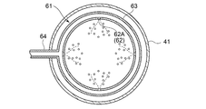
- the pipe 61 includes an annular portion 63 having a circular shape in plan view, and at least a part 62A of the plurality of injection holes 62 is formed in the annular portion 63.
- the cleaning liquid is sprayed from the plurality of injection holes 62 ⁇ / b> A provided in the annular portion 63 distributed in the circumferential direction of the annular portion 63, the cleaning liquid is injected into the annular portion in the suction casing 41.
- 63 can be dispersed in the circumferential direction.
- the cleaning liquid dispersed in the circumferential direction can diffuse before reaching the impeller 31. As a result, the cleaning liquid spreads uniformly over the entire width of the flow path, and the surfaces of the impellers 31 to 33 can be thoroughly cleaned without any unevenness.
- the diameter and installation position of the annular portion 63 can be arbitrarily set.
- the diameter may be a large diameter along the inner wall of the suction casing 41, or the diameter may be inscribed in the inlet 21, and the center of the flow path You may install concentrically. If the diameter is large along the inner wall of the suction casing 41, the cleaning liquid flows along the inner wall of the suction casing 41, and the cleaning liquid can be spread across both sides of the flow path width.
- the cleaning liquid can be prevented from adhering to the inner wall of the suction casing 41, and the impellers 31 to The waste of the cleaning liquid that is not used for cleaning 33 can be reduced.
- the cleaning liquid is ejected toward the center of the annular portion 63 from the plurality of injection holes 62 ⁇ / b> A provided on the inner peripheral surface of the annular portion 63, so that the cleaning liquid is disposed inside the annular portion 63.
- it can be uniformly dispersed in the circumferential direction. Since the cleaning liquid jetting direction intersects the fluid flow direction, the cleaning liquid uniformly dispersed in the circumferential direction is diffused by the fluid flow.
- the cleaning liquid spreads uniformly over the entire width of the flow path, and the surfaces of the impellers 31 to 33 can be thoroughly cleaned without any unevenness. Further, since the cleaning liquid is ejected from the annular portion 63 toward the radially inner side, it is possible to suppress the cleaning liquid from adhering to the inner wall surface of the suction casing 41. Accordingly, it is possible to reduce the waste of the cleaning liquid that is not used for cleaning the impellers 31 to 33.
- the circumferential position and diameter of the plurality of injection holes 62A provided on the inner peripheral surface of the annular portion 63 can be arbitrarily set.
- the distribution of the plurality of injection holes 62A is distributed so that the cleaning liquid is uniformly injected.
- the diameter of the plurality of injection holes 62A may be the same in the circumferential direction of the annular portion 63.
- the distribution of the plurality of injection holes 62 ⁇ / b> A may be roughened in a region near the supply unit 64 that supplies the cleaning liquid and dense in a region far from the supply unit 64. Good. In this way, since the cleaning liquid is uniformly sprayed in the suction casing 41, the cleaning liquid is uniformly distributed over the entire width of the flow path, and the surfaces of the impellers 31 to 33 are sufficiently cleaned as a whole. be able to.
- FIG. 7 is a cross-sectional view schematically showing a cleaning liquid ejecting apparatus according to an embodiment.
- the plurality of injection holes 62 are provided on the upstream side of the annular portion 63 and open obliquely upstream. .
- the cleaning liquid is sufficiently diffused by the fluid H flowing inside the suction casing 41. Is done.
- the cleaning liquid spreads uniformly over the entire width of the flow path, and the surfaces of the impellers 31 to 33 can be thoroughly cleaned without unevenness as a whole.
- the circumferential positions and diameters of the plurality of injection holes 62B provided on the upstream side of the annular portion 63 can be arbitrarily set.
- the distribution of the plurality of injection holes 62B is set so that the cleaning liquid is uniformly injected.
- the annular portion 63 may be uniform, and the plurality of injection holes 62B may have the same diameter.
- the distribution of the plurality of injection holes 62A may be rough in a region near the supply unit 64 that supplies the cleaning liquid and dense in a region far from the supply unit 64. . In this way, since the cleaning liquid is uniformly sprayed in the suction casing 41, the cleaning liquid is uniformly distributed over the entire width of the flow path, and the surfaces of the impellers 31 to 33 are sufficiently cleaned as a whole. be able to.
- the pipe 61 includes a small-diameter annular portion 65 having a smaller diameter than the annular portion 63 and concentric with the annular portion 63.
- the injection holes 62 are distributed in the circumferential direction of the small diameter annular portion 65 and provided in the small diameter annular portion 65. According to this configuration, since the cleaning liquid is sprayed from the plurality of injection holes 62 ⁇ / b> C provided in the small diameter annular portion 65 distributed in the circumferential direction of the small diameter annular portion 65, the suction casing 41 separated from the annular portion 63. The cleaning liquid can be reliably supplied also to the center of the interior.
- the cleaning liquid injected from the injection hole 62 ⁇ / b> C provided in the small-diameter annular portion 65 is sufficiently diffused by the fluid flowing through the center inside the suction casing 41.
- the cleaning liquid spreads uniformly over the entire width of the flow path, and the surfaces of the impellers 31 to 33 can be thoroughly cleaned without unevenness as a whole.
- the diameter of the small-diameter annular portion 65 can be arbitrarily set as long as it is smaller than the annular portion 63. Therefore, for example, the ring portion 63 may have a large diameter along the inner wall of the suction casing 41, and the small diameter ring portion 65 may have a diameter inscribed in the inlet 21, and may be installed at the center of the flow path. Further, the small-diameter annular portion 65 does not have to be flush with the annular portion. For example, the small-diameter annular portion 65 may be installed on the downstream side of the annular portion 63.
- the circumferential positions and diameters of the plurality of injection holes 62C provided in the small-diameter annular portion 65 can be arbitrarily set.
- the distribution of the plurality of injection holes 62C is distributed so that the cleaning liquid is uniformly injected. It may be uniform in the circumferential direction of the small-diameter annular portion 65, and the diameters of the plurality of injection holes 62C may be the same.
- the distribution of the plurality of injection holes 62A may be roughened in a region near the supply unit 64 that supplies the cleaning liquid and dense in a region far from the supply unit 64. . In this way, since the cleaning liquid is uniformly sprayed in the suction casing 41, the cleaning liquid is uniformly distributed over the entire width of the flow path, and the surfaces of the impellers 31 to 33 are sufficiently cleaned as a whole. be able to.
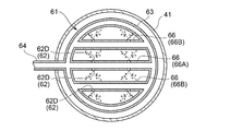
- the pipe 61 includes at least one straight portion 66 connecting two points on the circumference of the annular portion 63, and at least a part of the plurality of injection holes 62.
- the injection holes 62 ⁇ / b> D are distributed in the longitudinal direction of the straight portion 66 and are provided in the straight portion 66. According to this configuration, since the cleaning liquid is sprayed from the plurality of spray holes 62D provided in the longitudinal direction of the straight line portion 66 connecting the two points of the annular portion 63, the suction casing separated from the annular portion 63 is provided. The cleaning liquid can be reliably supplied also to the inner center of 41.
- the cleaning liquid injected from the injection hole 62 ⁇ / b> D provided in the straight portion 66 is sufficiently diffused by the fluid flowing through the center inside the suction casing 41.
- the cleaning liquid spreads uniformly over the entire width of the flow path, and the surfaces of the impellers 31 to 33 can be thoroughly cleaned without unevenness as a whole.
- the circumferential positions and diameters of the plurality of injection holes 62 ⁇ / b> D provided in the linear portion 66 can be arbitrarily set. For example, they may be provided at equal intervals so that the cleaning liquid is uniformly injected, or the region close to the supply unit 64. It may be provided so as to be rough and dense in a region away from the supply unit. In this case, the diameters of the plurality of injection holes 62D are the same, and the cleaning liquid having the same flow rate is injected from each injection hole 62D. In this way, the surfaces of the impellers 31 to 33 can be thoroughly cleaned without unevenness as a whole.
- the pipe 61 includes a first straight portion 66A passing through the center of the annular portion, and a second straight portion 66B provided on both sides of the first straight portion 66A in parallel with the first straight portion 66A. And. At least some of the plurality of injection holes 62 are distributed in the longitudinal direction of the first straight part 66A and the second straight part 66B and are provided in the first straight part 66A and the second straight part 66B. ing. The plurality of injection holes 62D are provided on both sides at least in the width direction of the first straight portion 66A.
- the cleaning liquid is ejected from the plurality of injection holes 62D provided distributed in the longitudinal direction of the first straight portion 66A, the cleaning liquid is sufficiently diffused by the fluid flowing through the inner center of the suction casing 41.
- the cleaning liquid spreads uniformly over the entire width of the flow path, and the surfaces of the impellers 31 to 33 can be thoroughly cleaned without unevenness as a whole.
- the circumferential position and diameter of the injection hole 62D provided in the longitudinal direction of the first linear portion 66A and the second linear portion 66B can be arbitrarily set.
- a plurality of injections are performed so that the cleaning liquid is uniformly injected.
- the holes 62D may be distributed in the longitudinal direction of the first straight part 66A and the second straight part 66B and provided in the first straight part 66A and the second straight part 66B.
- the diameters of the plurality of injection holes 62D are the same, and the cleaning liquid having the same flow rate is injected from each injection hole 62D. In this way, since the cleaning liquid is sprayed uniformly, the cleaning liquid is evenly distributed over the entire width of the flow path, and the surfaces of the impellers 31 to 33 can be sufficiently cleaned evenly as a whole.
- the pipe 61 includes at least one protruding portion 67 protruding from the annular portion 63 toward the radial center, and at least a part of the injection holes 62 is injected.
- the hole 62E is provided in the protruding portion 67.
- the pipe 61 includes four projecting portions 67 projecting from the respective positions (annular portion 63) that divide the annular portion 63 into four parts in the circumferential direction toward the center in the radial direction, and the injection holes 62. At least a part of the injection holes 62 ⁇ / b> E is provided in the projecting portion 67. More specifically, at least some of the injection holes 62 ⁇ / b> E of the injection holes 62 are provided on both sides in the width direction of the protrusion 67 and the protrusion 67.
- the cleaning liquid is ejected from the injection holes 62E provided in the protruding portion 67, the cleaning liquid is sufficiently diffused by the fluid flowing through the inner center of the suction casing 41. As a result, the cleaning liquid spreads uniformly over the entire width of the flow path, and the surfaces of the impellers 31 to 33 can be thoroughly cleaned without unevenness as a whole.
- FIG. 8 is a plan sectional view schematically showing a cleaning liquid ejecting apparatus according to an embodiment.
- the pipe 61 includes at least one straight line portion 68, and the plurality of injection holes 62 ⁇ / b> E are distributed in the longitudinal direction of the at least one straight line portion 68. At least one straight portion 68 is provided.
- the cleaning liquid since the cleaning liquid is ejected from the plurality of injection holes 62 ⁇ / b> E distributed and provided in the linear portion 68, the cleaning liquid can be dispersed in the longitudinal direction of the linear portion in the suction casing 41.
- the cleaning liquid dispersed in the longitudinal direction can diffuse before reaching the impellers 31 to 33. As a result, the cleaning liquid spreads uniformly over the entire width of the flow path, and the surfaces of the impellers 31 to 33 can be thoroughly cleaned without any unevenness.
- the installation position of the straight portion 68 can be arbitrarily set, but may be installed so as to cross the flow path of the suction casing 41, for example. If it is installed so as to cross the flow path of the suction casing 41, the cleaning liquid is evenly injected into the center of the flow path of the suction casing 41, so that the cleaning liquid is evenly distributed over the entire width of the flow path, and the impellers 31 to 33 It is possible to sufficiently clean the surface of the entire surface.
- FIG. 9 is a cross-sectional view schematically showing a cleaning / injecting apparatus according to an embodiment.
- the plurality of injection holes 62 ⁇ / b> F are provided on the upstream side of at least one straight portion 68 and open obliquely upstream.
- the cleaning liquid is jetted obliquely upstream from the plurality of injection holes 62F provided on the upstream side of at least one linear portion 68, the cleaning liquid is sufficiently supplied by the fluid H flowing inside the suction casing 41. Diffused.
- the cleaning liquid spreads uniformly over the entire width of the flow path, and the surfaces of the impellers 31 to 33 can be thoroughly cleaned without unevenness as a whole.
- the longitudinal positions and diameters of the plurality of injection holes 62F provided on the upstream side of the straight portion 68 can be arbitrarily set.
- the plurality of injection holes 62F are provided at equal intervals so that the cleaning liquid is uniformly injected. Also good. Further, it may be provided so as to be dense in the central region and rough in both side regions which are both sides thereof, or may be provided so as to be rough in the central region and dense in both side regions which are both sides thereof.
- the diameters of the plurality of injection holes 62F are the same, and the cleaning liquid having the same flow rate is injected from each of the injection holes 62F. In this way, since the cleaning liquid is sprayed uniformly, the cleaning liquid is evenly distributed over the entire width of the flow path, and the surfaces of the impellers 31 to 33 can be sufficiently cleaned evenly as a whole.
- the plurality of injection holes 62 ⁇ / b> F are provided on both sides in the width direction of at least one linear portion 68.
- the cleaning liquid is disposed in the suction casing 41 in the longitudinal direction of the linear portion 68. It can be uniformly distributed along the direction. Then, the cleaning liquid uniformly dispersed along the longitudinal direction of the linear portion 68 can diffuse until reaching the impellers 31 to 33. As a result, the cleaning liquid spreads uniformly over the entire width of the flow path, and the surfaces of the impellers 31 to 33 can be thoroughly cleaned without unevenness as a whole.
- the cross-sectional shapes of the pipe 61, the annular portion 63, the small-diameter annular portion 65, the straight portion 66, the first straight portion 66A, the second straight portion 66B, the protruding portion 67, and the straight portion 68 described above are used for jetting the cleaning liquid.
- Any suitable shape can be selected.
- a circular shape, an elliptical shape, an oval shape, a streamline shape, or a teardrop shape can be arbitrarily selected.
- the flow passage cross-sectional areas of the pipe 61, the annular portion 63, the small-diameter annular portion 65, the straight portion 66, the first straight portion 66A, the second straight portion 66B, the protruding portion 67, and the straight portion 68 are determined by jetting the cleaning liquid.
- the flow rate or pressure of the cleaning liquid sprayed from the plurality of spray holes 62, 62A, 62B, 62C, 62D, and 62E is set to a uniform size.
- the cross-sectional shapes of the pipe 61, the annular portion 63, the small-diameter annular portion 65, the straight portion 66, the first straight portion 66A, the second straight portion 66B, the protruding portion 67, and the straight portion 68 are circular.
- the cross-sectional area of the injection holes 62, 62A, 62B, 62C, 62D, 62E is set to 10 times or more.
- the pipe 61 may include an annular portion 63 and a straight portion 68, and may be installed with a position shifted in the direction of the axis M, for example.
- the annular portion 63 is installed at the entrance 21 and the straight portion 68 is installed between the annular portion and the entrance 21.
Abstract
L'invention porte sur un compresseur centrifuge, qui comporte : un carter principal qui a une entrée et une sortie ; au moins un rotor qui est disposé de manière rotative à l'intérieur du carter principal ; un carter d'aspiration, qui est relié à l'entrée précédemment mentionnée, et qui a un orifice d'aspiration dans une position éloignée de l'entrée dans la direction axiale ; un dispositif d'injection de solution de nettoyage, qui peut être disposé adjacent à l'orifice d'aspiration à l'intérieur du carter d'aspiration ; et un dispositif de distribution de solution de nettoyage, qui distribue une solution de nettoyage au dispositif d'injection de solution de nettoyage. Le dispositif d'injection de solution de nettoyage comprend, à l'intérieur du carter d'aspiration, un tuyau qui peut être disposé de façon à s'étendre le long d'un plan croisant la direction axiale, et de multiples trous d'injection pratiqués dans ledit tuyau.
Priority Applications (3)
| Application Number | Priority Date | Filing Date | Title |
|---|---|---|---|
| CN201580035234.2A CN106471261A (zh) | 2014-09-19 | 2015-04-17 | 离心压缩机 |
| US15/503,145 US20170226881A1 (en) | 2014-09-19 | 2015-04-17 | Centrifugal compressor |
| EP15842413.5A EP3196481A1 (fr) | 2014-09-19 | 2015-04-17 | Compresseur centrifuge |
Applications Claiming Priority (2)
| Application Number | Priority Date | Filing Date | Title |
|---|---|---|---|
| JP2014-191514 | 2014-09-19 | ||
| JP2014191514A JP2016061261A (ja) | 2014-09-19 | 2014-09-19 | 遠心圧縮機 |
Publications (1)
| Publication Number | Publication Date |
|---|---|
| WO2016042826A1 true WO2016042826A1 (fr) | 2016-03-24 |
Family
ID=55532873
Family Applications (1)
| Application Number | Title | Priority Date | Filing Date |
|---|---|---|---|
| PCT/JP2015/061885 WO2016042826A1 (fr) | 2014-09-19 | 2015-04-17 | Compresseur centrifuge |
Country Status (5)
| Country | Link |
|---|---|
| US (1) | US20170226881A1 (fr) |
| EP (1) | EP3196481A1 (fr) |
| JP (1) | JP2016061261A (fr) |
| CN (1) | CN106471261A (fr) |
| WO (1) | WO2016042826A1 (fr) |
Cited By (1)
| Publication number | Priority date | Publication date | Assignee | Title |
|---|---|---|---|---|
| US11073167B2 (en) | 2018-10-25 | 2021-07-27 | Mitsubishi Heavy Industries Compressor Corporation | Compressor |
Families Citing this family (1)
| Publication number | Priority date | Publication date | Assignee | Title |
|---|---|---|---|---|
| IT201800021067A1 (it) * | 2018-12-27 | 2020-06-27 | Nuovo Pignone Tecnologie Srl | Componenti aerodinamici statorici con ugelli e metodi per pulire una turbomacchina |
Citations (4)
| Publication number | Priority date | Publication date | Assignee | Title |
|---|---|---|---|---|
| JP2007040307A (ja) * | 2005-08-04 | 2007-02-15 | General Electric Co <Ge> | ガスタービンのオンライン圧縮機水洗浄システム |
| JP2008069778A (ja) * | 2006-09-11 | 2008-03-27 | Gas Turbine Efficiency Sweden Ab | タービン出力を増加するためのシステム及びその増加方法 |
| JP2009115079A (ja) * | 2007-10-09 | 2009-05-28 | Gas Turbine Efficiency Sweden Ab | ガスタービンコンプレッサの水洗浄装置と洗浄方法 |
| JP2012229701A (ja) * | 2009-08-21 | 2012-11-22 | Gas Turbine Efficiency Sweden Ab | 多段化されたコンプレッサ水洗システム |
Family Cites Families (5)
| Publication number | Priority date | Publication date | Assignee | Title |
|---|---|---|---|---|
| JPH05141397A (ja) * | 1991-11-15 | 1993-06-08 | Hitachi Ltd | 羽根車を有する回転機械の羽根車洗浄装置 |
| JPH07269302A (ja) * | 1994-03-30 | 1995-10-17 | Mitsubishi Heavy Ind Ltd | 軸流圧縮機の翼洗浄方法および装置 |
| JPH08338397A (ja) * | 1995-06-14 | 1996-12-24 | Hitachi Ltd | 一軸多段遠心圧縮機の羽根車洗浄装置 |
| US6413043B1 (en) * | 2000-11-09 | 2002-07-02 | General Electric Company | Inlet guide vane and shroud support contact |
| US8197609B2 (en) * | 2006-11-28 | 2012-06-12 | Pratt & Whitney Line Maintenance Services, Inc. | Automated detection and control system and method for high pressure water wash application and collection applied to aero compressor washing |
-
2014
- 2014-09-19 JP JP2014191514A patent/JP2016061261A/ja not_active Withdrawn
-
2015
- 2015-04-17 WO PCT/JP2015/061885 patent/WO2016042826A1/fr active Application Filing
- 2015-04-17 US US15/503,145 patent/US20170226881A1/en not_active Abandoned
- 2015-04-17 EP EP15842413.5A patent/EP3196481A1/fr not_active Withdrawn
- 2015-04-17 CN CN201580035234.2A patent/CN106471261A/zh active Pending
Patent Citations (4)
| Publication number | Priority date | Publication date | Assignee | Title |
|---|---|---|---|---|
| JP2007040307A (ja) * | 2005-08-04 | 2007-02-15 | General Electric Co <Ge> | ガスタービンのオンライン圧縮機水洗浄システム |
| JP2008069778A (ja) * | 2006-09-11 | 2008-03-27 | Gas Turbine Efficiency Sweden Ab | タービン出力を増加するためのシステム及びその増加方法 |
| JP2009115079A (ja) * | 2007-10-09 | 2009-05-28 | Gas Turbine Efficiency Sweden Ab | ガスタービンコンプレッサの水洗浄装置と洗浄方法 |
| JP2012229701A (ja) * | 2009-08-21 | 2012-11-22 | Gas Turbine Efficiency Sweden Ab | 多段化されたコンプレッサ水洗システム |
Cited By (1)
| Publication number | Priority date | Publication date | Assignee | Title |
|---|---|---|---|---|
| US11073167B2 (en) | 2018-10-25 | 2021-07-27 | Mitsubishi Heavy Industries Compressor Corporation | Compressor |
Also Published As
| Publication number | Publication date |
|---|---|
| JP2016061261A (ja) | 2016-04-25 |
| CN106471261A (zh) | 2017-03-01 |
| EP3196481A1 (fr) | 2017-07-26 |
| US20170226881A1 (en) | 2017-08-10 |
Similar Documents
| Publication | Publication Date | Title |
|---|---|---|
| JP2010127245A (ja) | 遠心圧縮機 | |
| TWI529027B (zh) | A liquid ejecting device for a processing machine | |
| JP2011153568A (ja) | 遠心圧縮機、および洗浄方法 | |
| KR20080036086A (ko) | 압축기, 압축기 휠, 세척 부속물 및 배기 터보 과급기 | |
| JP6442048B2 (ja) | 二流体ノズル | |
| WO2016042826A1 (fr) | Compresseur centrifuge | |
| JP6367660B2 (ja) | 遠心圧縮機 | |
| JP2008025579A5 (fr) | ||
| KR100880913B1 (ko) | 덕트용 청소튜브 | |
| JP5575308B2 (ja) | 遠心圧縮機 | |
| JP5956760B2 (ja) | 洗浄ノズル | |
| JP6521702B2 (ja) | ターボ型流体機械の洗浄装置及びターボ型流体機械 | |
| JP2008075738A (ja) | 軸受装置 | |
| JP5869044B2 (ja) | 遠心圧縮機 | |
| JP5461143B2 (ja) | 遠心圧縮機 | |
| JP5827105B2 (ja) | 洗浄ノズルおよびホースの洗浄方法 | |
| US20140284396A1 (en) | Snow making apparatus | |
| JP2011115735A (ja) | 油井管用鋼管内面乾燥ノズル | |
| JP2016061261A5 (fr) | ||
| JP5307680B2 (ja) | 遠心圧縮機 | |
| JP5536261B2 (ja) | 遠心圧縮機 | |
| JP2008020001A (ja) | スピンドル装置 | |
| JP2016180349A (ja) | 回転機械 | |
| KR101623033B1 (ko) | 액상 원료 다단 혼합형 믹서 | |
| JP7108515B2 (ja) | 圧縮機 |
Legal Events
| Date | Code | Title | Description |
|---|---|---|---|
| 121 | Ep: the epo has been informed by wipo that ep was designated in this application |
Ref document number: 15842413 Country of ref document: EP Kind code of ref document: A1 |
|
| REEP | Request for entry into the european phase |
Ref document number: 2015842413 Country of ref document: EP |
|
| WWE | Wipo information: entry into national phase |
Ref document number: 2015842413 Country of ref document: EP |
|
| NENP | Non-entry into the national phase |
Ref country code: DE |