WO2016042826A1 - Centrifugal compressor - Google Patents
Centrifugal compressor Download PDFInfo
- Publication number
- WO2016042826A1 WO2016042826A1 PCT/JP2015/061885 JP2015061885W WO2016042826A1 WO 2016042826 A1 WO2016042826 A1 WO 2016042826A1 JP 2015061885 W JP2015061885 W JP 2015061885W WO 2016042826 A1 WO2016042826 A1 WO 2016042826A1
- Authority
- WO
- WIPO (PCT)
- Prior art keywords
- cleaning liquid
- annular portion
- injection holes
- centrifugal compressor
- pipe
- Prior art date
Links
Images


Classifications
-
- F—MECHANICAL ENGINEERING; LIGHTING; HEATING; WEAPONS; BLASTING
- F01—MACHINES OR ENGINES IN GENERAL; ENGINE PLANTS IN GENERAL; STEAM ENGINES
- F01D—NON-POSITIVE DISPLACEMENT MACHINES OR ENGINES, e.g. STEAM TURBINES
- F01D9/00—Stators
- F01D9/06—Fluid supply conduits to nozzles or the like
- F01D9/065—Fluid supply or removal conduits traversing the working fluid flow, e.g. for lubrication-, cooling-, or sealing fluids
-
- F—MECHANICAL ENGINEERING; LIGHTING; HEATING; WEAPONS; BLASTING
- F04—POSITIVE - DISPLACEMENT MACHINES FOR LIQUIDS; PUMPS FOR LIQUIDS OR ELASTIC FLUIDS
- F04D—NON-POSITIVE-DISPLACEMENT PUMPS
- F04D29/00—Details, component parts, or accessories
- F04D29/70—Suction grids; Strainers; Dust separation; Cleaning
- F04D29/701—Suction grids; Strainers; Dust separation; Cleaning especially adapted for elastic fluid pumps
- F04D29/705—Adding liquids
-
- B—PERFORMING OPERATIONS; TRANSPORTING
- B08—CLEANING
- B08B—CLEANING IN GENERAL; PREVENTION OF FOULING IN GENERAL
- B08B3/00—Cleaning by methods involving the use or presence of liquid or steam
- B08B3/02—Cleaning by the force of jets or sprays
-
- F—MECHANICAL ENGINEERING; LIGHTING; HEATING; WEAPONS; BLASTING
- F01—MACHINES OR ENGINES IN GENERAL; ENGINE PLANTS IN GENERAL; STEAM ENGINES
- F01D—NON-POSITIVE DISPLACEMENT MACHINES OR ENGINES, e.g. STEAM TURBINES
- F01D25/00—Component parts, details, or accessories, not provided for in, or of interest apart from, other groups
- F01D25/24—Casings; Casing parts, e.g. diaphragms, casing fastenings
-
- F—MECHANICAL ENGINEERING; LIGHTING; HEATING; WEAPONS; BLASTING
- F04—POSITIVE - DISPLACEMENT MACHINES FOR LIQUIDS; PUMPS FOR LIQUIDS OR ELASTIC FLUIDS
- F04D—NON-POSITIVE-DISPLACEMENT PUMPS
- F04D29/00—Details, component parts, or accessories
- F04D29/60—Mounting; Assembling; Disassembling
- F04D29/62—Mounting; Assembling; Disassembling of radial or helico-centrifugal pumps
-
- F—MECHANICAL ENGINEERING; LIGHTING; HEATING; WEAPONS; BLASTING
- F04—POSITIVE - DISPLACEMENT MACHINES FOR LIQUIDS; PUMPS FOR LIQUIDS OR ELASTIC FLUIDS
- F04D—NON-POSITIVE-DISPLACEMENT PUMPS
- F04D29/00—Details, component parts, or accessories
- F04D29/70—Suction grids; Strainers; Dust separation; Cleaning
-
- F—MECHANICAL ENGINEERING; LIGHTING; HEATING; WEAPONS; BLASTING
- F01—MACHINES OR ENGINES IN GENERAL; ENGINE PLANTS IN GENERAL; STEAM ENGINES
- F01D—NON-POSITIVE DISPLACEMENT MACHINES OR ENGINES, e.g. STEAM TURBINES
- F01D25/00—Component parts, details, or accessories, not provided for in, or of interest apart from, other groups
- F01D25/002—Cleaning of turbomachines
Definitions
- This disclosure relates to centrifugal compressors.
- Patent Document 1 discloses a centrifugal compressor including a main casing having an inlet and an outlet, and an impeller disposed rotatably inside the main casing.
- a centrifugal compressor includes an impeller to be cleaned, a supply pipe that supplies a cleaning liquid, and a cleaning liquid injection nozzle that is provided on the inlet side of the main casing and injects the cleaning liquid supplied from the supply pipe onto the surface of the impeller. Yes.
- the dust adhering to the impeller surface is washed away by the cleaning liquid.
- the cleaning liquid is sprayed from one cleaning liquid spray nozzle provided near the inlet of the main casing.
- the cleaning liquid injected from the cleaning liquid injection nozzle does not spread sufficiently to reach the impeller. For this reason, there is a possibility that the cleaning liquid does not spread uniformly over the entire width of the flow path, and the surface of the impeller cannot be cleaned sufficiently evenly as a whole.
- At least one embodiment of the present invention provides a centrifugal compressor in which the cleaning liquid can be uniformly distributed over the entire width of the flow path and the surface of the impeller can be thoroughly cleaned without unevenness.
- the purpose is to provide.
- a centrifugal compressor includes: A main casing having an inlet and an outlet; At least one impeller rotatably disposed inside the main casing; A suction casing connected to the inlet and having a suction port at a position spaced axially from the inlet; A cleaning liquid ejecting apparatus that can be disposed on the suction port side in the suction casing; A cleaning liquid supply device for supplying a cleaning liquid to the cleaning liquid injection device; The cleaning liquid ejecting apparatus includes: In the inside of the suction casing, a pipe that can be arranged to extend along a plane that intersects the axial direction; A plurality of injection holes provided in the pipe.
- the cleaning liquid can be dispersed in the suction casing by spraying the cleaning liquid from the plurality of injection holes. And, since the cleaning liquid dispersed in the suction casing spreads sufficiently until it reaches the impeller, the cleaning liquid is evenly distributed over the entire width of the flow path, and the surface of the impeller is thoroughly cleaned evenly. Can do.
- the pipe in the configuration of (1) above, can reciprocate between an operating position inside the suction casing and a retracted position outside the suction casing. According to the configuration of the above (2), the pipe can be positioned at the operating position when the impeller is cleaned, and the pipe can be retracted to the retracted position at the normal time. Can be reduced.
- the pipe includes an annular portion having an annular shape in plan view,
- the plurality of injection holes are distributed in the circumferential direction of the annular portion and provided in the annular portion.
- the cleaning liquid is sprayed from the plurality of injection holes provided in the annular part distributed in the circumferential direction of the annular part, the cleaning liquid is injected into the annular part in the suction casing. Can be dispersed in the circumferential direction. Then, the cleaning liquid dispersed in the circumferential direction can diffuse before reaching the impeller. As a result, the cleaning liquid is evenly distributed over the entire width of the flow path, and the surface of the impeller can be thoroughly cleaned without unevenness as a whole.
- the cleaning liquid is ejected from the plurality of injection holes provided on the inner peripheral surface of the annular portion toward the center of the annular portion, so that the cleaning liquid is disposed inside the annular portion.
- the cleaning liquid jetting direction intersects the fluid flow direction
- the cleaning liquid uniformly dispersed in the circumferential direction is diffused by the fluid flow. For this reason, the cleaning liquid spreads uniformly over the entire width of the flow path, and the surface of the impeller can be thoroughly cleaned without unevenness as a whole.
- the cleaning liquid is jetted radially inward from the annular portion, it is possible to suppress the cleaning liquid from adhering to the inner wall surface of the suction casing. Thereby, the waste of the cleaning liquid that is not used for cleaning the impeller can be reduced.
- At least a part of the plurality of injection holes is provided on the upstream side of the annular portion.
- the cleaning liquid is sufficiently diffused by the fluid flowing inside the suction casing.
- the cleaning liquid can be uniformly distributed over the entire width of the flow path, and the surface of the impeller can be thoroughly cleaned without unevenness as a whole.
- the pipe in any one of the above configurations (3) to (5), includes a small-diameter annular portion having an annular shape in plan view and having a smaller diameter than the annular portion and concentrically with the annular portion, At least a part of the plurality of injection holes is distributed in the circumferential direction of the small diameter annular portion and provided in the small diameter annular portion.
- the cleaning liquid is sprayed from the plurality of injection holes provided in the small-diameter annular portion distributed in the circumferential direction of the small-diameter annular portion. The cleaning liquid can be reliably supplied to the inner center.
- cleaning liquid injected from the injection hole provided in the small diameter annular part is fully spread
- the cleaning liquid can be uniformly distributed over the entire width of the flow path, and the surface of the impeller can be thoroughly cleaned without unevenness as a whole.
- the pipe includes at least one straight portion connecting two points on the circumference of the annular portion, At least a part of the plurality of injection holes is distributed in the longitudinal direction of the at least one straight portion and provided in the straight portion.
- the cleaning liquid is sprayed from the plurality of spray holes provided distributed in the longitudinal direction of the straight portion connecting the two points of the annular portion, so that the suction casing separated from the annular portion
- the cleaning liquid can be reliably supplied also to the center of the interior.
- cleaning liquid injected from the injection hole provided in the linear part is fully spread
- the cleaning liquid can be uniformly distributed over the entire width of the flow path, and the surface of the impeller can be thoroughly cleaned without unevenness as a whole.
- the pipe includes at least one projecting portion projecting from the annular portion toward the radial center, At least a part of the injection hole is provided in the protrusion.
- the cleaning liquid since the cleaning liquid is ejected from the injection hole provided in the protrusion, the cleaning liquid can be reliably supplied to the inner center of the suction casing away from the annular portion. And the washing
- the pipe includes at least one straight line portion,
- the plurality of injection holes are distributed in the longitudinal direction of the at least one straight portion and provided in the at least one straight portion.
- the cleaning liquid since the cleaning liquid is ejected from the plurality of injection holes provided distributed in the straight portion, the cleaning liquid can be dispersed in the longitudinal direction of the straight portion in the suction casing. Then, the cleaning liquid dispersed in the longitudinal direction can diffuse before reaching the impeller. As a result, the cleaning liquid is evenly distributed over the entire width of the flow path, and the surface of the impeller can be thoroughly cleaned without unevenness as a whole.
- the plurality of injection holes are provided on the upstream side of the at least one straight portion. According to the configuration of (10), since the cleaning liquid is injected from the plurality of injection holes provided on the upstream side of at least one straight line portion, the cleaning liquid is sufficiently diffused by the fluid flowing inside the suction casing. As a result, the cleaning liquid can be uniformly distributed over the entire width of the flow path, and the surface of the impeller can be thoroughly cleaned without unevenness as a whole.
- the plurality of injection holes are provided on both sides in the width direction of the at least one linear portion.
- the cleaning liquid is ejected from the plurality of injection holes provided on both sides in the width direction of at least one linear section. It can be uniformly distributed along the direction. And the washing
- the cleaning liquid can be uniformly distributed over the entire width of the flow path, and the surface of the impeller can be thoroughly cleaned without unevenness.
- FIG. 2 is a longitudinal sectional view showing a state in which the cleaning liquid washing and ejecting apparatus shown in FIG. 1 is advanced to an operating position by a solid line, and a state in which the cleaning liquid ejecting apparatus is retracted to a retracted position by a virtual line.
- It is a plane sectional view showing roughly the cleaning fluid injection device concerning one embodiment. It is a plane sectional view showing roughly the cleaning fluid injection device concerning one embodiment. It is a plane sectional view showing roughly the cleaning fluid injection device concerning one embodiment. It is a plane sectional view showing roughly the cleaning fluid injection device concerning one embodiment. It is a plane sectional view showing roughly the cleaning fluid injection device concerning one embodiment.
- expressions representing shapes such as quadrangular shapes and cylindrical shapes not only represent shapes such as quadrangular shapes and cylindrical shapes in a strict geometric sense, but also within the range where the same effect can be obtained. A shape including a chamfered portion or the like is also expressed.
- the expressions “comprising”, “comprising”, “comprising”, “including”, or “having” one constituent element are not exclusive expressions for excluding the existence of the other constituent elements.
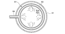
- FIG. 1 is a cross-sectional view schematically showing a configuration of a centrifugal compressor 1 according to an embodiment of the present invention.
- a centrifugal compressor 1 according to an embodiment of the present invention is a single-shaft multi-stage centrifugal compressor, and includes a main casing 2, at least one impeller 3, suction casings 41 and 42, a discharge casing 51, 52, a cleaning liquid ejecting apparatus 6 and a cleaning liquid supply apparatus 7 are provided.
- the main casing 2 has inlets 21 and 22 and outlets 23 and 24.
- the main casing 2 according to this embodiment has two inlets 21 and 22 and two outlets 23 and 24, respectively.
- the rotary shaft 37 is rotatably disposed through the main casing 2. Specifically, the rotary shaft 37 is rotatably supported by journal bearings 27A and 27B and thrust bearings 28A and 28B installed on both sides of the main casing 2, respectively.
- the inlets 21 and 22 and the outlets 23 and 24 are arranged along the rotation axis 37. In FIG. 1, the inlet 21, the outlet 23, the outlet 24, and the inlet 22 are arranged in this order from the left side. Adjacent inlet 21 and outlet 23 make a pair, and adjacent inlet 22 and outlet 24 make a pair.
- the outlet 23 and the inlet 22 are connected to each other by a pipe (not shown).
- impellers 31 to 33 and impellers 34 to 36 are rotatably arranged inside the main casing 2, as at least one impeller 3, impellers 31 to 33 and impellers 34 to 36 are rotatably arranged.
- Each of the impellers 31 to 33 and the impellers 34 to 36 is fixed concentrically with respect to the rotating shaft 37.
- the impellers 31 to 33 are fixed in series to a portion of a rotating shaft 37 extending between the inlet 21 and the outlet 23, and the impellers 34 to 36 are rotating shafts extending between the inlet 22 and the outlet 24.
- the portion 37 is fixed in series.
- Each of the impellers 31 to 33 and the impellers 34 to 36 forms a flow path R inside the main casing 2.
- diffusers 25 and 26 are provided as stationary flow paths that connect the flow paths R of the impellers 31 to 33 and the impellers 34 to 36 in series.
- the suction casings 41 and 42 are connected to the inlets 21 and 22, and have suction ports 41 ⁇ / b> A and 42 ⁇ / b> A at positions separated from the inlets 21 and 22 in the axis M and N directions of the suction casings 41 and 42, for example, downward.
- the suction casings 41 and 42 are gradually reduced in diameter from the suction ports 41 ⁇ / b> A and 42 ⁇ / b> A toward the inlets 21 and 22, and the flow passage cross-sectional area gradually decreases from the suction ports 41 ⁇ / b> A and 42 ⁇ / b> A toward the inlets 21 and 22.
- the suction casings 41 and 42 are configured so that the flow passage cross-sectional shape on the suction ports 41A and 42A side is a circular shape, and the flow passage cross-sectional shape on the inlets 21 and 22 side is a rectangular shape.
- the cross-sectional shape of the flow path of the suction casings 41, 42 gradually changes from a circular shape to a rectangular shape from the 42A side toward the inlets 21, 22 side.
- the discharge casings 51 and 52 are connected to the outlets 23 and 24, and have discharge ports 51A and 52A at positions separated from the outlets 23 and 24 in the axial direction of the discharge casings 51 and 52, for example, downward.
- the axial directions M and N of the suction casings 41 and 42 and the axial direction of the discharge casings 51 and 52 are orthogonal to the axial direction of the rotary shaft 37.
- the centrifugal compressor 1 the fluid to be compressed flows into the suction casing 41 from the suction port 41 ⁇ / b> A by rotating the rotary shaft 37.
- the fluid to be compressed passes through the inlet 21 and passes through the flow path R of the rotating impellers 31 to 33 and the diffuser 25 to be compressed. Thereafter, the compressed fluid passes through the outlet 23 and the discharge casing 51 and is once discharged out of the main casing 2.
- the fluid discharged from the discharge casing 51 is cooled by, for example, a cooling device (not shown), and then flows into the suction casing 42 from the suction port 42A.
- the fluid that has flowed in is compressed through the inlet 22 and the passage R of the rotating impellers 34 to 36 and the diffuser 26. Thereafter, the compressed fluid passes through the outlet 24 and the discharge casing 52 and is discharged out of the main casing 2.
- the cleaning liquid ejecting apparatus 6 can be disposed on the suction port 41 ⁇ / b> A side inside one suction casing 41, and the cleaning liquid is supplied from the cleaning liquid supply apparatus 7 to the cleaning liquid ejecting apparatus 6.
- the cleaning liquid is intermittently supplied from the cleaning liquid supply device 7 to the cleaning liquid injection device 6 while the centrifugal compressor 1 is in operation.
- the cleaning liquid supplied to the cleaning liquid ejecting apparatus 6 is jetted onto the fluid to be compressed that has flowed into the suction casing 41, is dispersed in the fluid to be compressed, and reaches the surfaces of the impellers 31 to 33 together with the fluid to be compressed.
- the cleaning liquid that has reached the surfaces of the impellers 31 to 33 cleans the surfaces of the impellers 31 to 33 by washing away dust adhering to the surfaces of the impellers 31 to 33.
- a pipe 61 that can be arranged so as to extend along a plane that intersects the direction of the axis M, and a plurality of injection holes 62 ( 3).
- the cleaning liquid can be dispersed in the suction casing 41 by spraying the cleaning liquid from the plurality of injection holes 62. Since the cleaning liquid dispersed in the suction casing 41 is sufficiently spread until it reaches the impeller 3, the cleaning liquid is evenly distributed over the entire width of the flow path, and the surfaces of the impellers 31 to 33 are not evenly distributed. It can be washed thoroughly.
- FIG. 2 shows a state where the pipe 61 shown in FIG. 1 is positioned at the operating position inside the suction casing 41 by a solid line, and shows a state where the pipe 61 is retracted at a retracted position outside the suction casing 41 (two-dot chain line). It is the longitudinal cross-sectional view shown by).
- the pipe 61 can reciprocate between an operating position inside the suction casing 41 and a retracted position outside the suction casing 41.
- the pipe 61 can be positioned at the operating position during impeller cleaning, and the pipe 61 can be retracted to the retracted position during normal operation.
- the flow path resistance in the suction casing 41 can be reduced at the time of normal time compared with the time of impeller cleaning.
- the pipe 61 can be reciprocated manually or by a power unit (not shown).
- a power unit for example, in the case of manual operation, the pipe 61 can be reciprocated by rotating a handle (not shown).
- the pipe 61 can be reciprocated by operating the power unit.
- the pipe 61 includes an annular portion 63 having a circular shape in plan view, and at least a part 62A of the plurality of injection holes 62 is formed in the annular portion 63.
- the cleaning liquid is sprayed from the plurality of injection holes 62 ⁇ / b> A provided in the annular portion 63 distributed in the circumferential direction of the annular portion 63, the cleaning liquid is injected into the annular portion in the suction casing 41.
- 63 can be dispersed in the circumferential direction.
- the cleaning liquid dispersed in the circumferential direction can diffuse before reaching the impeller 31. As a result, the cleaning liquid spreads uniformly over the entire width of the flow path, and the surfaces of the impellers 31 to 33 can be thoroughly cleaned without any unevenness.
- the diameter and installation position of the annular portion 63 can be arbitrarily set.
- the diameter may be a large diameter along the inner wall of the suction casing 41, or the diameter may be inscribed in the inlet 21, and the center of the flow path You may install concentrically. If the diameter is large along the inner wall of the suction casing 41, the cleaning liquid flows along the inner wall of the suction casing 41, and the cleaning liquid can be spread across both sides of the flow path width.
- the cleaning liquid can be prevented from adhering to the inner wall of the suction casing 41, and the impellers 31 to The waste of the cleaning liquid that is not used for cleaning 33 can be reduced.
- the cleaning liquid is ejected toward the center of the annular portion 63 from the plurality of injection holes 62 ⁇ / b> A provided on the inner peripheral surface of the annular portion 63, so that the cleaning liquid is disposed inside the annular portion 63.
- it can be uniformly dispersed in the circumferential direction. Since the cleaning liquid jetting direction intersects the fluid flow direction, the cleaning liquid uniformly dispersed in the circumferential direction is diffused by the fluid flow.
- the cleaning liquid spreads uniformly over the entire width of the flow path, and the surfaces of the impellers 31 to 33 can be thoroughly cleaned without any unevenness. Further, since the cleaning liquid is ejected from the annular portion 63 toward the radially inner side, it is possible to suppress the cleaning liquid from adhering to the inner wall surface of the suction casing 41. Accordingly, it is possible to reduce the waste of the cleaning liquid that is not used for cleaning the impellers 31 to 33.
- the circumferential position and diameter of the plurality of injection holes 62A provided on the inner peripheral surface of the annular portion 63 can be arbitrarily set.
- the distribution of the plurality of injection holes 62A is distributed so that the cleaning liquid is uniformly injected.
- the diameter of the plurality of injection holes 62A may be the same in the circumferential direction of the annular portion 63.
- the distribution of the plurality of injection holes 62 ⁇ / b> A may be roughened in a region near the supply unit 64 that supplies the cleaning liquid and dense in a region far from the supply unit 64. Good. In this way, since the cleaning liquid is uniformly sprayed in the suction casing 41, the cleaning liquid is uniformly distributed over the entire width of the flow path, and the surfaces of the impellers 31 to 33 are sufficiently cleaned as a whole. be able to.
- FIG. 7 is a cross-sectional view schematically showing a cleaning liquid ejecting apparatus according to an embodiment.
- the plurality of injection holes 62 are provided on the upstream side of the annular portion 63 and open obliquely upstream. .
- the cleaning liquid is sufficiently diffused by the fluid H flowing inside the suction casing 41. Is done.
- the cleaning liquid spreads uniformly over the entire width of the flow path, and the surfaces of the impellers 31 to 33 can be thoroughly cleaned without unevenness as a whole.
- the circumferential positions and diameters of the plurality of injection holes 62B provided on the upstream side of the annular portion 63 can be arbitrarily set.
- the distribution of the plurality of injection holes 62B is set so that the cleaning liquid is uniformly injected.
- the annular portion 63 may be uniform, and the plurality of injection holes 62B may have the same diameter.
- the distribution of the plurality of injection holes 62A may be rough in a region near the supply unit 64 that supplies the cleaning liquid and dense in a region far from the supply unit 64. . In this way, since the cleaning liquid is uniformly sprayed in the suction casing 41, the cleaning liquid is uniformly distributed over the entire width of the flow path, and the surfaces of the impellers 31 to 33 are sufficiently cleaned as a whole. be able to.
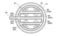
- the pipe 61 includes a small-diameter annular portion 65 having a smaller diameter than the annular portion 63 and concentric with the annular portion 63.
- the injection holes 62 are distributed in the circumferential direction of the small diameter annular portion 65 and provided in the small diameter annular portion 65. According to this configuration, since the cleaning liquid is sprayed from the plurality of injection holes 62 ⁇ / b> C provided in the small diameter annular portion 65 distributed in the circumferential direction of the small diameter annular portion 65, the suction casing 41 separated from the annular portion 63. The cleaning liquid can be reliably supplied also to the center of the interior.
- the cleaning liquid injected from the injection hole 62 ⁇ / b> C provided in the small-diameter annular portion 65 is sufficiently diffused by the fluid flowing through the center inside the suction casing 41.
- the cleaning liquid spreads uniformly over the entire width of the flow path, and the surfaces of the impellers 31 to 33 can be thoroughly cleaned without unevenness as a whole.
- the diameter of the small-diameter annular portion 65 can be arbitrarily set as long as it is smaller than the annular portion 63. Therefore, for example, the ring portion 63 may have a large diameter along the inner wall of the suction casing 41, and the small diameter ring portion 65 may have a diameter inscribed in the inlet 21, and may be installed at the center of the flow path. Further, the small-diameter annular portion 65 does not have to be flush with the annular portion. For example, the small-diameter annular portion 65 may be installed on the downstream side of the annular portion 63.
- the circumferential positions and diameters of the plurality of injection holes 62C provided in the small-diameter annular portion 65 can be arbitrarily set.
- the distribution of the plurality of injection holes 62C is distributed so that the cleaning liquid is uniformly injected. It may be uniform in the circumferential direction of the small-diameter annular portion 65, and the diameters of the plurality of injection holes 62C may be the same.
- the distribution of the plurality of injection holes 62A may be roughened in a region near the supply unit 64 that supplies the cleaning liquid and dense in a region far from the supply unit 64. . In this way, since the cleaning liquid is uniformly sprayed in the suction casing 41, the cleaning liquid is uniformly distributed over the entire width of the flow path, and the surfaces of the impellers 31 to 33 are sufficiently cleaned as a whole. be able to.
- the pipe 61 includes at least one straight portion 66 connecting two points on the circumference of the annular portion 63, and at least a part of the plurality of injection holes 62.
- the injection holes 62 ⁇ / b> D are distributed in the longitudinal direction of the straight portion 66 and are provided in the straight portion 66. According to this configuration, since the cleaning liquid is sprayed from the plurality of spray holes 62D provided in the longitudinal direction of the straight line portion 66 connecting the two points of the annular portion 63, the suction casing separated from the annular portion 63 is provided. The cleaning liquid can be reliably supplied also to the inner center of 41.
- the cleaning liquid injected from the injection hole 62 ⁇ / b> D provided in the straight portion 66 is sufficiently diffused by the fluid flowing through the center inside the suction casing 41.
- the cleaning liquid spreads uniformly over the entire width of the flow path, and the surfaces of the impellers 31 to 33 can be thoroughly cleaned without unevenness as a whole.
- the circumferential positions and diameters of the plurality of injection holes 62 ⁇ / b> D provided in the linear portion 66 can be arbitrarily set. For example, they may be provided at equal intervals so that the cleaning liquid is uniformly injected, or the region close to the supply unit 64. It may be provided so as to be rough and dense in a region away from the supply unit. In this case, the diameters of the plurality of injection holes 62D are the same, and the cleaning liquid having the same flow rate is injected from each injection hole 62D. In this way, the surfaces of the impellers 31 to 33 can be thoroughly cleaned without unevenness as a whole.
- the pipe 61 includes a first straight portion 66A passing through the center of the annular portion, and a second straight portion 66B provided on both sides of the first straight portion 66A in parallel with the first straight portion 66A. And. At least some of the plurality of injection holes 62 are distributed in the longitudinal direction of the first straight part 66A and the second straight part 66B and are provided in the first straight part 66A and the second straight part 66B. ing. The plurality of injection holes 62D are provided on both sides at least in the width direction of the first straight portion 66A.
- the cleaning liquid is ejected from the plurality of injection holes 62D provided distributed in the longitudinal direction of the first straight portion 66A, the cleaning liquid is sufficiently diffused by the fluid flowing through the inner center of the suction casing 41.
- the cleaning liquid spreads uniformly over the entire width of the flow path, and the surfaces of the impellers 31 to 33 can be thoroughly cleaned without unevenness as a whole.
- the circumferential position and diameter of the injection hole 62D provided in the longitudinal direction of the first linear portion 66A and the second linear portion 66B can be arbitrarily set.
- a plurality of injections are performed so that the cleaning liquid is uniformly injected.
- the holes 62D may be distributed in the longitudinal direction of the first straight part 66A and the second straight part 66B and provided in the first straight part 66A and the second straight part 66B.
- the diameters of the plurality of injection holes 62D are the same, and the cleaning liquid having the same flow rate is injected from each injection hole 62D. In this way, since the cleaning liquid is sprayed uniformly, the cleaning liquid is evenly distributed over the entire width of the flow path, and the surfaces of the impellers 31 to 33 can be sufficiently cleaned evenly as a whole.
- the pipe 61 includes at least one protruding portion 67 protruding from the annular portion 63 toward the radial center, and at least a part of the injection holes 62 is injected.
- the hole 62E is provided in the protruding portion 67.
- the pipe 61 includes four projecting portions 67 projecting from the respective positions (annular portion 63) that divide the annular portion 63 into four parts in the circumferential direction toward the center in the radial direction, and the injection holes 62. At least a part of the injection holes 62 ⁇ / b> E is provided in the projecting portion 67. More specifically, at least some of the injection holes 62 ⁇ / b> E of the injection holes 62 are provided on both sides in the width direction of the protrusion 67 and the protrusion 67.
- the cleaning liquid is ejected from the injection holes 62E provided in the protruding portion 67, the cleaning liquid is sufficiently diffused by the fluid flowing through the inner center of the suction casing 41. As a result, the cleaning liquid spreads uniformly over the entire width of the flow path, and the surfaces of the impellers 31 to 33 can be thoroughly cleaned without unevenness as a whole.
- FIG. 8 is a plan sectional view schematically showing a cleaning liquid ejecting apparatus according to an embodiment.
- the pipe 61 includes at least one straight line portion 68, and the plurality of injection holes 62 ⁇ / b> E are distributed in the longitudinal direction of the at least one straight line portion 68. At least one straight portion 68 is provided.
- the cleaning liquid since the cleaning liquid is ejected from the plurality of injection holes 62 ⁇ / b> E distributed and provided in the linear portion 68, the cleaning liquid can be dispersed in the longitudinal direction of the linear portion in the suction casing 41.
- the cleaning liquid dispersed in the longitudinal direction can diffuse before reaching the impellers 31 to 33. As a result, the cleaning liquid spreads uniformly over the entire width of the flow path, and the surfaces of the impellers 31 to 33 can be thoroughly cleaned without any unevenness.
- the installation position of the straight portion 68 can be arbitrarily set, but may be installed so as to cross the flow path of the suction casing 41, for example. If it is installed so as to cross the flow path of the suction casing 41, the cleaning liquid is evenly injected into the center of the flow path of the suction casing 41, so that the cleaning liquid is evenly distributed over the entire width of the flow path, and the impellers 31 to 33 It is possible to sufficiently clean the surface of the entire surface.
- FIG. 9 is a cross-sectional view schematically showing a cleaning / injecting apparatus according to an embodiment.
- the plurality of injection holes 62 ⁇ / b> F are provided on the upstream side of at least one straight portion 68 and open obliquely upstream.
- the cleaning liquid is jetted obliquely upstream from the plurality of injection holes 62F provided on the upstream side of at least one linear portion 68, the cleaning liquid is sufficiently supplied by the fluid H flowing inside the suction casing 41. Diffused.
- the cleaning liquid spreads uniformly over the entire width of the flow path, and the surfaces of the impellers 31 to 33 can be thoroughly cleaned without unevenness as a whole.
- the longitudinal positions and diameters of the plurality of injection holes 62F provided on the upstream side of the straight portion 68 can be arbitrarily set.
- the plurality of injection holes 62F are provided at equal intervals so that the cleaning liquid is uniformly injected. Also good. Further, it may be provided so as to be dense in the central region and rough in both side regions which are both sides thereof, or may be provided so as to be rough in the central region and dense in both side regions which are both sides thereof.
- the diameters of the plurality of injection holes 62F are the same, and the cleaning liquid having the same flow rate is injected from each of the injection holes 62F. In this way, since the cleaning liquid is sprayed uniformly, the cleaning liquid is evenly distributed over the entire width of the flow path, and the surfaces of the impellers 31 to 33 can be sufficiently cleaned evenly as a whole.
- the plurality of injection holes 62 ⁇ / b> F are provided on both sides in the width direction of at least one linear portion 68.
- the cleaning liquid is disposed in the suction casing 41 in the longitudinal direction of the linear portion 68. It can be uniformly distributed along the direction. Then, the cleaning liquid uniformly dispersed along the longitudinal direction of the linear portion 68 can diffuse until reaching the impellers 31 to 33. As a result, the cleaning liquid spreads uniformly over the entire width of the flow path, and the surfaces of the impellers 31 to 33 can be thoroughly cleaned without unevenness as a whole.
- the cross-sectional shapes of the pipe 61, the annular portion 63, the small-diameter annular portion 65, the straight portion 66, the first straight portion 66A, the second straight portion 66B, the protruding portion 67, and the straight portion 68 described above are used for jetting the cleaning liquid.
- Any suitable shape can be selected.
- a circular shape, an elliptical shape, an oval shape, a streamline shape, or a teardrop shape can be arbitrarily selected.
- the flow passage cross-sectional areas of the pipe 61, the annular portion 63, the small-diameter annular portion 65, the straight portion 66, the first straight portion 66A, the second straight portion 66B, the protruding portion 67, and the straight portion 68 are determined by jetting the cleaning liquid.
- the flow rate or pressure of the cleaning liquid sprayed from the plurality of spray holes 62, 62A, 62B, 62C, 62D, and 62E is set to a uniform size.
- the cross-sectional shapes of the pipe 61, the annular portion 63, the small-diameter annular portion 65, the straight portion 66, the first straight portion 66A, the second straight portion 66B, the protruding portion 67, and the straight portion 68 are circular.
- the cross-sectional area of the injection holes 62, 62A, 62B, 62C, 62D, 62E is set to 10 times or more.
- the pipe 61 may include an annular portion 63 and a straight portion 68, and may be installed with a position shifted in the direction of the axis M, for example.
- the annular portion 63 is installed at the entrance 21 and the straight portion 68 is installed between the annular portion and the entrance 21.
Abstract
This centrifugal compressor is provided with: a main casing which has an inlet and an outlet; at least one impeller which is rotatably arranged inside of the main casing; a suction casing which is connected to the aforementioned inlet and which has a suction port in a position spaced away from the inlet in the axial direction; a cleaning solution injection device which can be arranged to the side of the suction port inside of the suction casing; and a cleaning solution supply device which supplies a cleaning solution to the cleaning solution injection device. The cleaning solution injection device comprises, inside of the suction casing, a pipe which can be arranged so as to extend along a plane intersecting the axial direction, and multiple injection holes provided in said pipe.
Description
本開示は遠心圧縮機に関する。
This disclosure relates to centrifugal compressors.
特許文献1には、入口及び出口を有するメインケーシングと、メインケーシングの内部に回転可能に配置されたインペラと、を備えた遠心圧縮機が開示されている。かかる遠心圧縮機は、インペラを洗浄対象とし、洗浄液を供給する供給配管と、メインケーシングの入口側に設けられ、供給配管から供給された洗浄液をインペラ表面に噴射する洗浄液噴射ノズルと、を備えている。かかる遠心圧縮機によれば、インペラ表面に付着したダストが洗浄液によって洗い流されるものとされている。
Patent Document 1 discloses a centrifugal compressor including a main casing having an inlet and an outlet, and an impeller disposed rotatably inside the main casing. Such a centrifugal compressor includes an impeller to be cleaned, a supply pipe that supplies a cleaning liquid, and a cleaning liquid injection nozzle that is provided on the inlet side of the main casing and injects the cleaning liquid supplied from the supply pipe onto the surface of the impeller. Yes. According to such a centrifugal compressor, the dust adhering to the impeller surface is washed away by the cleaning liquid.
特許文献1が開示する遠心圧縮機では、メインケーシングの入口付近に設けられた一つの洗浄液噴射ノズルから洗浄液が噴射されている。この場合、洗浄液噴射ノズルが一つしかなく、且つ、洗浄液噴射ノズルからインペラまでの距離が短いため、洗浄液噴射ノズルから噴射された洗浄液がインペラに到達するまでに十分に広がらない。このため、洗浄液が流路幅の全域に渡って均一に行き渡らず、インペラの表面を全体的にむらなく十分に洗浄することができない虞がある。
In the centrifugal compressor disclosed in Patent Document 1, the cleaning liquid is sprayed from one cleaning liquid spray nozzle provided near the inlet of the main casing. In this case, since there is only one cleaning liquid injection nozzle and the distance from the cleaning liquid injection nozzle to the impeller is short, the cleaning liquid injected from the cleaning liquid injection nozzle does not spread sufficiently to reach the impeller. For this reason, there is a possibility that the cleaning liquid does not spread uniformly over the entire width of the flow path, and the surface of the impeller cannot be cleaned sufficiently evenly as a whole.
上述の事情に鑑みて、本発明の少なくとも一実施形態は、洗浄液が流路幅の全域に渡って均一に行き渡り、インペラの表面を全体的にむらなく十分に洗浄することができる遠心圧縮機を提供することを目的とする。
In view of the above circumstances, at least one embodiment of the present invention provides a centrifugal compressor in which the cleaning liquid can be uniformly distributed over the entire width of the flow path and the surface of the impeller can be thoroughly cleaned without unevenness. The purpose is to provide.
(1)本発明の少なくとも一実施形態に係る遠心圧縮機は、
入口及び出口を有するメインケーシングと、
前記メインケーシングの内部に回転可能に配置された少なくとも一つのインペラと、
前記入口に接続され、前記入口から軸線方向に離隔した位置に吸込口を有する吸込ケーシングと、
前記吸込ケーシングの内部における前記吸込口側に配置可能な洗浄液噴射装置と、
前記洗浄液噴射装置に洗浄液を供給する洗浄液供給装置と
を備え、
前記洗浄液噴射装置は、
前記吸込ケーシングの内部において、前記軸線方向と交差する面に沿って延在するように配置可能なパイプと、
前記パイプに設けられた複数の噴射孔と
を有する。 (1) A centrifugal compressor according to at least one embodiment of the present invention includes:
A main casing having an inlet and an outlet;
At least one impeller rotatably disposed inside the main casing;
A suction casing connected to the inlet and having a suction port at a position spaced axially from the inlet;
A cleaning liquid ejecting apparatus that can be disposed on the suction port side in the suction casing;
A cleaning liquid supply device for supplying a cleaning liquid to the cleaning liquid injection device;
The cleaning liquid ejecting apparatus includes:
In the inside of the suction casing, a pipe that can be arranged to extend along a plane that intersects the axial direction;
A plurality of injection holes provided in the pipe.
上記(1)の構成によれば、複数の噴射孔から洗浄液が噴射されることで、吸込ケーシング内で洗浄液を分散させることができる。そして、吸込ケーシング内で分散された洗浄液がインペラに到達するまでに十分に広がるので、洗浄液が流路幅の全域に渡って均一に行き渡り、インペラの表面を全体的にむらなく十分に洗浄することができる。
According to the configuration of (1) above, the cleaning liquid can be dispersed in the suction casing by spraying the cleaning liquid from the plurality of injection holes. And, since the cleaning liquid dispersed in the suction casing spreads sufficiently until it reaches the impeller, the cleaning liquid is evenly distributed over the entire width of the flow path, and the surface of the impeller is thoroughly cleaned evenly. Can do.
(2)幾つかの実施形態では、上記(1)の構成において、
前記パイプは、前記吸込ケーシングの内部の作動位置と前記吸込ケーシングの外部の待避位置との間を往復可能である。
上記(2)の構成によれば、インペラの洗浄時にパイプを作動位置に位置させ、通常時にパイプを待避位置に待避させることができるので、通常時にはインペラ洗浄時よりも吸込ケーシング内の流路抵抗を減少させることができる。 (2) In some embodiments, in the configuration of (1) above,
The pipe can reciprocate between an operating position inside the suction casing and a retracted position outside the suction casing.
According to the configuration of the above (2), the pipe can be positioned at the operating position when the impeller is cleaned, and the pipe can be retracted to the retracted position at the normal time. Can be reduced.
(3)幾つかの実施形態では、上記(1)又は(2)の構成において、
前記パイプは、平面視円環状の円環部を含み、
前記複数の噴射孔は、前記円環部の周方向に分布して前記円環部に設けられる。
上記(3)の構成によれば、円環部の周方向に分布して円環部に設けられた複数の噴射孔から洗浄液が噴射されるので、洗浄液を、吸込ケーシング内において、円環部の周方向に分散させることができる。そして、周方向に分散した洗浄液は、インペラに到達するまでに拡散することができる。この結果、洗浄液が流路幅の全域に渡って均一に行き渡り、インペラの表面を全体的にむらなく十分に洗浄することができる。 (3) In some embodiments, in the above configuration (1) or (2),
The pipe includes an annular portion having an annular shape in plan view,
The plurality of injection holes are distributed in the circumferential direction of the annular portion and provided in the annular portion.
According to the configuration of the above (3), since the cleaning liquid is sprayed from the plurality of injection holes provided in the annular part distributed in the circumferential direction of the annular part, the cleaning liquid is injected into the annular part in the suction casing. Can be dispersed in the circumferential direction. Then, the cleaning liquid dispersed in the circumferential direction can diffuse before reaching the impeller. As a result, the cleaning liquid is evenly distributed over the entire width of the flow path, and the surface of the impeller can be thoroughly cleaned without unevenness as a whole.
(4)幾つかの実施形態では、上記(3)の構成において、
前記複数の噴射孔のうち少なくとも一部は、前記円環部の内周面に設けられる。
上記(4)の構成によれば、円環部の内周面に設けられた複数の噴射孔から円環部の中心に向けて洗浄液が噴射されることで、洗浄液を、円環部の内側にて、周方向に均一に分散させることができる。そして、洗浄液の噴射方向が流体の流れ方向に対し交差しているので、周方向に均一に分散した洗浄液が流体の流れにより拡散される。このため、洗浄液が流路幅の全域に渡って均一に行き渡り、インペラの表面を全体的にむらなく十分に洗浄することができる。また、円環部から径方向内側に向かって洗浄液が噴射されるので、吸込ケーシングの内壁面に洗浄液が付着するのを抑制できる。これにより、インペラの洗浄に用いられない洗浄液の無駄を少なくすることができる。 (4) In some embodiments, in the configuration of (3) above,
At least a part of the plurality of injection holes is provided on the inner peripheral surface of the annular portion.
According to the configuration of (4) above, the cleaning liquid is ejected from the plurality of injection holes provided on the inner peripheral surface of the annular portion toward the center of the annular portion, so that the cleaning liquid is disposed inside the annular portion. Thus, it can be uniformly dispersed in the circumferential direction. Since the cleaning liquid jetting direction intersects the fluid flow direction, the cleaning liquid uniformly dispersed in the circumferential direction is diffused by the fluid flow. For this reason, the cleaning liquid spreads uniformly over the entire width of the flow path, and the surface of the impeller can be thoroughly cleaned without unevenness as a whole. Further, since the cleaning liquid is jetted radially inward from the annular portion, it is possible to suppress the cleaning liquid from adhering to the inner wall surface of the suction casing. Thereby, the waste of the cleaning liquid that is not used for cleaning the impeller can be reduced.
(5)幾つかの実施形態では、上記(3)の構成において、
前記複数の噴射孔のうち少なくとも一部は、前記円環部の上流側に設けられる。
上記(5)の構成によれば、円環部の上流側に設けられた複数の噴射孔から洗浄液が噴射されるので、吸込ケーシングの内部を流れる流体によって洗浄液が十分に拡散される。これにより、洗浄液が流路幅の全域に渡って均一に行き渡り、インペラの表面を全体的にむらなく十分に洗浄することができる。 (5) In some embodiments, in the configuration of (3) above,
At least a part of the plurality of injection holes is provided on the upstream side of the annular portion.
According to the configuration of (5) above, since the cleaning liquid is injected from the plurality of injection holes provided on the upstream side of the annular portion, the cleaning liquid is sufficiently diffused by the fluid flowing inside the suction casing. As a result, the cleaning liquid can be uniformly distributed over the entire width of the flow path, and the surface of the impeller can be thoroughly cleaned without unevenness as a whole.
(6)幾つかの実施形態では、上記(3)~(5)の何れか一つの構成において、
前記パイプは、前記円環部よりも小径で且つ前記円環部と同心上に配置される平面視円環状の小径円環部を含み、
前記複数の噴射孔のうち少なくとも一部は、前記小径円環部の周方向に分布して前記小径円環部に設けられる。
上記(6)の構成によれば、小径円環部の周方向に分布して小径円環部に設けられた複数の噴射孔から洗浄液が噴射されるので、円環部から離れた吸込ケーシングの内部中央にも洗浄液を確実に供給することができる。そして、小径円環部に設けられた噴射孔から噴射された洗浄液は、吸込ケーシングの内部中央を流れる流体によって十分に拡散される。これにより、洗浄液が流路幅の全域に渡って均一に行き渡り、インペラの表面を全体的にむらなく十分に洗浄することができる。 (6) In some embodiments, in any one of the above configurations (3) to (5),
The pipe includes a small-diameter annular portion having an annular shape in plan view and having a smaller diameter than the annular portion and concentrically with the annular portion,
At least a part of the plurality of injection holes is distributed in the circumferential direction of the small diameter annular portion and provided in the small diameter annular portion.
According to the configuration of (6) above, the cleaning liquid is sprayed from the plurality of injection holes provided in the small-diameter annular portion distributed in the circumferential direction of the small-diameter annular portion. The cleaning liquid can be reliably supplied to the inner center. And the washing | cleaning liquid injected from the injection hole provided in the small diameter annular part is fully spread | diffused with the fluid which flows through the inner center of a suction casing. As a result, the cleaning liquid can be uniformly distributed over the entire width of the flow path, and the surface of the impeller can be thoroughly cleaned without unevenness as a whole.
(7)幾つかの実施形態では、上記(3)~(5)の何れか一つの構成において、
前記パイプは、前記円環部の円周上の二点を結ぶ少なくとも一つの直線部を含み、
前記複数の噴射孔のうち少なくとも一部は、前記少なくとも一つの直線部の長手方向に分布して前記直線部に設けられる。
上記(7)の構成によれば、円環部の二点を結ぶ直線部の長手方向に分布して設けられた複数の噴射孔から洗浄液が噴射されるので、円環部から離れた吸込ケーシングの内部中央にも洗浄液を確実に供給することができる。そして、直線部に設けられた噴射孔から噴射された洗浄液は、吸込ケーシングの内部中央を流れる流体によって十分に拡散される。これにより、洗浄液が流路幅の全域に渡って均一に行き渡り、インペラの表面を全体的にむらなく十分に洗浄することができる。 (7) In some embodiments, in any one of the above configurations (3) to (5),
The pipe includes at least one straight portion connecting two points on the circumference of the annular portion,
At least a part of the plurality of injection holes is distributed in the longitudinal direction of the at least one straight portion and provided in the straight portion.
According to the configuration of (7) above, the cleaning liquid is sprayed from the plurality of spray holes provided distributed in the longitudinal direction of the straight portion connecting the two points of the annular portion, so that the suction casing separated from the annular portion The cleaning liquid can be reliably supplied also to the center of the interior. And the washing | cleaning liquid injected from the injection hole provided in the linear part is fully spread | diffused with the fluid which flows through the inner center of a suction casing. As a result, the cleaning liquid can be uniformly distributed over the entire width of the flow path, and the surface of the impeller can be thoroughly cleaned without unevenness as a whole.
(8)幾つかの実施形態では、上記(3)~(5)の何れか一つの構成において、
前記パイプは、前記円環部から径方向中心に向けて突出する少なくとも一つの突出部を含み、
前記噴射孔のうち少なくとも一部は、前記突出部に設けられる。
上記(8)の構成によれば、突出部に設けられた噴射孔から洗浄液が噴射されるので、円環部から離れた吸込ケーシングの内部中央にも洗浄液を確実に供給することができる。そして、突出部に設けられた噴射孔から噴射された洗浄液は、吸込ケーシングの内部中央を流れる流体によって十分に拡散される。これにより、洗浄液が流路幅の全域に渡って均一に行き渡り、インペラの表面を全体的にむらなく十分に洗浄することができる。 (8) In some embodiments, in any one of the above configurations (3) to (5),
The pipe includes at least one projecting portion projecting from the annular portion toward the radial center,
At least a part of the injection hole is provided in the protrusion.
According to the configuration of (8) above, since the cleaning liquid is ejected from the injection hole provided in the protrusion, the cleaning liquid can be reliably supplied to the inner center of the suction casing away from the annular portion. And the washing | cleaning liquid injected from the injection hole provided in the protrusion part is fully spread | diffused with the fluid which flows through the inner center of a suction casing. As a result, the cleaning liquid can be uniformly distributed over the entire width of the flow path, and the surface of the impeller can be thoroughly cleaned without unevenness as a whole.
(9)幾つかの実施形態では、上記(1)又は(2)の何れか一つの構成において、
前記パイプは、少なくとも一つの直線状の直線部を含み、
前記複数の噴射孔は、前記少なくとも一つの直線部の長手方向に分布して前記少なくとも一つの直線部に設けられる。
上記(9)の構成によれば、直線部に分布して設けられる複数の噴射孔から洗浄液が噴射されるので、洗浄液を、吸込ケーシング内において、直線部の長手方向に分散させることができる。そして、長手方向に分散した洗浄液は、インペラに到達するまでに拡散することができる。この結果、洗浄液が流路幅の全域に渡って均一に行き渡り、インペラの表面を全体的にむらなく十分に洗浄することができる。 (9) In some embodiments, in any one of the configurations (1) and (2) above,
The pipe includes at least one straight line portion,
The plurality of injection holes are distributed in the longitudinal direction of the at least one straight portion and provided in the at least one straight portion.
According to the configuration of (9), since the cleaning liquid is ejected from the plurality of injection holes provided distributed in the straight portion, the cleaning liquid can be dispersed in the longitudinal direction of the straight portion in the suction casing. Then, the cleaning liquid dispersed in the longitudinal direction can diffuse before reaching the impeller. As a result, the cleaning liquid is evenly distributed over the entire width of the flow path, and the surface of the impeller can be thoroughly cleaned without unevenness as a whole.
(10)幾つかの実施形態では、上記(9)の構成において、
前記複数の噴射孔は、前記少なくとも一つの直線部の上流側に設けられる。
上記(10)の構成によれば、少なくとも一つの直線部の上流側に設けられる複数の噴射孔から洗浄液が噴射されるので、吸込ケーシングの内部を流れる流体によって洗浄液が十分に拡散される。これにより、洗浄液が流路幅の全域に渡って均一に行き渡り、インペラの表面を全体的にむらなく十分に洗浄することができる。 (10) In some embodiments, in the configuration of (9) above,
The plurality of injection holes are provided on the upstream side of the at least one straight portion.
According to the configuration of (10), since the cleaning liquid is injected from the plurality of injection holes provided on the upstream side of at least one straight line portion, the cleaning liquid is sufficiently diffused by the fluid flowing inside the suction casing. As a result, the cleaning liquid can be uniformly distributed over the entire width of the flow path, and the surface of the impeller can be thoroughly cleaned without unevenness as a whole.
(11)幾つかの実施形態では、上記(9)又は(10)の構成において、
前記複数の噴射孔は、前記少なくとも一つの直線部の幅方向にて両方の側に設けられる。
上記(11)の構成によれば、少なくとも一つの直線部の幅方向にて両方の側に設けられる複数の噴射孔から洗浄液が噴射されるので、洗浄液を、吸込ケーシング内において、直線部の長手方向に沿って均一に分散させることができる。そして、直線部の長手方向に沿って均一に分散された洗浄液が、インペラに到達するまでに拡散することができる。これにより、洗浄液が流路幅の全域に渡って均一に行き渡り、インペラの表面を全体的にむらなく十分に洗浄することができる。 (11) In some embodiments, in the above configuration (9) or (10),
The plurality of injection holes are provided on both sides in the width direction of the at least one linear portion.
According to the configuration of (11) above, the cleaning liquid is ejected from the plurality of injection holes provided on both sides in the width direction of at least one linear section. It can be uniformly distributed along the direction. And the washing | cleaning liquid disperse | distributed uniformly along the longitudinal direction of a linear part can be spread | diffused before reaching | attaining an impeller. As a result, the cleaning liquid can be uniformly distributed over the entire width of the flow path, and the surface of the impeller can be thoroughly cleaned without unevenness as a whole.
本発明の少なくとも一実施形態によれば、洗浄液が流路幅の全域に渡って均一に行き渡り、インペラの表面を全体的にむらなく十分に洗浄することができる。
According to at least one embodiment of the present invention, the cleaning liquid can be uniformly distributed over the entire width of the flow path, and the surface of the impeller can be thoroughly cleaned without unevenness.
以下、添付図面を参照して本発明の幾つかの実施形態について説明する。ただし、実施形態として記載されている又は図面に示されている構成部品の寸法、材質、形状、その相対的配置等は、本発明の範囲をこれに限定する趣旨ではなく、単なる説明例にすぎない。
例えば、「ある方向に」、「ある方向に沿って」、「平行」、「直交」、「中心」、「同心」或いは「同軸」等の相対的或いは絶対的な配置を表す表現は、厳密にそのような配置を表すのみならず、公差、若しくは、同じ機能が得られる程度の角度や距離をもって相対的に変位している状態も表すものとする。
また例えば、四角形状や円筒形状等の形状を表す表現は、幾何学的に厳密な意味での四角形状や円筒形状等の形状を表すのみならず、同じ効果が得られる範囲で、凹凸部や面取り部等を含む形状も表すものとする。
一方、一の構成要素を「備える」、「具える」、「具備する」、「含む」、又は、「有する」という表現は、他の構成要素の存在を除外する排他的な表現ではない。 Hereinafter, some embodiments of the present invention will be described with reference to the accompanying drawings. However, the dimensions, materials, shapes, relative arrangements, etc. of the components described in the embodiments or shown in the drawings are not intended to limit the scope of the present invention, but are merely illustrative examples. Absent.
For example, expressions expressing relative or absolute arrangements such as “in a certain direction”, “along a certain direction”, “parallel”, “orthogonal”, “center”, “concentric” or “coaxial” are strictly In addition to such an arrangement, it is also possible to represent a state of relative displacement with an angle or a distance such that tolerance or the same function can be obtained.
In addition, for example, expressions representing shapes such as quadrangular shapes and cylindrical shapes not only represent shapes such as quadrangular shapes and cylindrical shapes in a strict geometric sense, but also within the range where the same effect can be obtained. A shape including a chamfered portion or the like is also expressed.
On the other hand, the expressions “comprising”, “comprising”, “comprising”, “including”, or “having” one constituent element are not exclusive expressions for excluding the existence of the other constituent elements.
図1は、本発明の一実施形態に係る遠心圧縮機1の構成を概略的に示す断面図である。
図1に示すように、本発明の実施形態に係る遠心圧縮機1は、一軸多段式の遠心圧縮機であり、メインケーシング2、少なくとも一つのインペラ3、吸込ケーシング41,42、吐出ケーシング51,52、洗浄液噴射装置6、及び、洗浄液供給装置7を備えている。 FIG. 1 is a cross-sectional view schematically showing a configuration of acentrifugal compressor 1 according to an embodiment of the present invention.
As shown in FIG. 1, acentrifugal compressor 1 according to an embodiment of the present invention is a single-shaft multi-stage centrifugal compressor, and includes a main casing 2, at least one impeller 3, suction casings 41 and 42, a discharge casing 51, 52, a cleaning liquid ejecting apparatus 6 and a cleaning liquid supply apparatus 7 are provided.
図1に示すように、本発明の実施形態に係る遠心圧縮機1は、一軸多段式の遠心圧縮機であり、メインケーシング2、少なくとも一つのインペラ3、吸込ケーシング41,42、吐出ケーシング51,52、洗浄液噴射装置6、及び、洗浄液供給装置7を備えている。 FIG. 1 is a cross-sectional view schematically showing a configuration of a
As shown in FIG. 1, a
メインケーシング2は入口21,22及び出口23,24を有する。本実施形態に係るメインケーシング2は、入口21,22及び出口23,24をそれぞれ二箇所ずつ有する。
The main casing 2 has inlets 21 and 22 and outlets 23 and 24. The main casing 2 according to this embodiment has two inlets 21 and 22 and two outlets 23 and 24, respectively.
一方、メインケーシング2を貫通して、回転軸37が回転可能に配置されている。具体的には、回転軸37はメインケーシング2の両側にそれぞれ設置されたジャーナルベアリング27A,27B及びスラストベアリング28A,28Bによって回転可能に支持されている。
入口21,22及び出口23,24は、回転軸37に沿って配列され、図1において、左側から順に、入口21、出口23、出口24及び入口22が配置されている。隣り合う入口21と出口23が対をなし、隣り合う入口22と出口24が対をなす。出口23と入口22が図示しない配管によって相互に接続される。 On the other hand, therotary shaft 37 is rotatably disposed through the main casing 2. Specifically, the rotary shaft 37 is rotatably supported by journal bearings 27A and 27B and thrust bearings 28A and 28B installed on both sides of the main casing 2, respectively.
The inlets 21 and 22 and the outlets 23 and 24 are arranged along the rotation axis 37. In FIG. 1, the inlet 21, the outlet 23, the outlet 24, and the inlet 22 are arranged in this order from the left side. Adjacent inlet 21 and outlet 23 make a pair, and adjacent inlet 22 and outlet 24 make a pair. The outlet 23 and the inlet 22 are connected to each other by a pipe (not shown).
入口21,22及び出口23,24は、回転軸37に沿って配列され、図1において、左側から順に、入口21、出口23、出口24及び入口22が配置されている。隣り合う入口21と出口23が対をなし、隣り合う入口22と出口24が対をなす。出口23と入口22が図示しない配管によって相互に接続される。 On the other hand, the
The
メインケーシング2の内部には、少なくとも一つのインペラ3として、インペラ31~33及びインペラ34~36が回転可能に配置されている。
インペラ31~33及びインペラ34~36の各々は、回転軸37に対し同心上に固定されている。具体的には、インペラ31~33は、入口21と出口23との間を延びる回転軸37の部分に直列に固定され、インペラ34~36は、入口22と出口24との間を延びる回転軸37の部分に直列に固定されている。
インペラ31~33及びインペラ34~36の各々は、メインケーシング2の内部に流路Rを形成している。メインケーシング2の内部には、インペラ31~33及びインペラ34~36の流路Rを直列に接続する静止流路として、ディフューザ25,26が設けられている。 Inside themain casing 2, as at least one impeller 3, impellers 31 to 33 and impellers 34 to 36 are rotatably arranged.
Each of theimpellers 31 to 33 and the impellers 34 to 36 is fixed concentrically with respect to the rotating shaft 37. Specifically, the impellers 31 to 33 are fixed in series to a portion of a rotating shaft 37 extending between the inlet 21 and the outlet 23, and the impellers 34 to 36 are rotating shafts extending between the inlet 22 and the outlet 24. The portion 37 is fixed in series.
Each of theimpellers 31 to 33 and the impellers 34 to 36 forms a flow path R inside the main casing 2. In the main casing 2, diffusers 25 and 26 are provided as stationary flow paths that connect the flow paths R of the impellers 31 to 33 and the impellers 34 to 36 in series.
インペラ31~33及びインペラ34~36の各々は、回転軸37に対し同心上に固定されている。具体的には、インペラ31~33は、入口21と出口23との間を延びる回転軸37の部分に直列に固定され、インペラ34~36は、入口22と出口24との間を延びる回転軸37の部分に直列に固定されている。
インペラ31~33及びインペラ34~36の各々は、メインケーシング2の内部に流路Rを形成している。メインケーシング2の内部には、インペラ31~33及びインペラ34~36の流路Rを直列に接続する静止流路として、ディフューザ25,26が設けられている。 Inside the
Each of the
Each of the
吸込ケーシング41,42は、入口21,22に接続され、入口21,22から吸込ケーシング41,42の軸線M,N方向、例えば下方に離隔した位置に吸込口41A,42Aを有する。吸込ケーシング41,42は、吸込口41A,42Aから入口21,22に向けて徐々に縮径され、吸込口41A,42Aから入口21,22に向けて流路断面積が徐々に減少する。本実施形態では、吸込ケーシング41,42は、吸込口41A,42A側の流路断面形状が円形形状となり、入口21,22側の流路断面形状が矩形形状となるように、吸込口41A,42A側から入口21,22側に向けて吸込ケーシング41,42の流路断面形状が円形形状から矩形形状に徐々に変形する。
The suction casings 41 and 42 are connected to the inlets 21 and 22, and have suction ports 41 </ b> A and 42 </ b> A at positions separated from the inlets 21 and 22 in the axis M and N directions of the suction casings 41 and 42, for example, downward. The suction casings 41 and 42 are gradually reduced in diameter from the suction ports 41 </ b> A and 42 </ b> A toward the inlets 21 and 22, and the flow passage cross-sectional area gradually decreases from the suction ports 41 </ b> A and 42 </ b> A toward the inlets 21 and 22. In the present embodiment, the suction casings 41 and 42 are configured so that the flow passage cross-sectional shape on the suction ports 41A and 42A side is a circular shape, and the flow passage cross-sectional shape on the inlets 21 and 22 side is a rectangular shape. The cross-sectional shape of the flow path of the suction casings 41, 42 gradually changes from a circular shape to a rectangular shape from the 42A side toward the inlets 21, 22 side.
吐出ケーシング51,52は、出口23,24に接続され、出口23,24から吐出ケーシング51,52の軸線方向、例えば下方に離隔した位置に吐出口51A,52Aを有する。例えば、吸込ケーシング41,42の軸線M,N方向及び吐出ケーシング51,52の軸線方向は、回転軸37の軸線方向と直交している。
遠心圧縮機1では、回転軸37を回転させることにより、圧縮対象の流体が吸込口41Aから吸込ケーシング41内に流入する。圧縮対象の流体は、入口21を経て、回転するインペラ31~33の流路R及びディフューザ25を通過して圧縮される。この後、圧縮された流体は、出口23及び吐出ケーシング51を通過し、一旦メインケーシング2の外に吐出される。 The discharge casings 51 and 52 are connected to the outlets 23 and 24, and have discharge ports 51A and 52A at positions separated from the outlets 23 and 24 in the axial direction of the discharge casings 51 and 52, for example, downward. For example, the axial directions M and N of the suction casings 41 and 42 and the axial direction of the discharge casings 51 and 52 are orthogonal to the axial direction of the rotary shaft 37.
In thecentrifugal compressor 1, the fluid to be compressed flows into the suction casing 41 from the suction port 41 </ b> A by rotating the rotary shaft 37. The fluid to be compressed passes through the inlet 21 and passes through the flow path R of the rotating impellers 31 to 33 and the diffuser 25 to be compressed. Thereafter, the compressed fluid passes through the outlet 23 and the discharge casing 51 and is once discharged out of the main casing 2.
遠心圧縮機1では、回転軸37を回転させることにより、圧縮対象の流体が吸込口41Aから吸込ケーシング41内に流入する。圧縮対象の流体は、入口21を経て、回転するインペラ31~33の流路R及びディフューザ25を通過して圧縮される。この後、圧縮された流体は、出口23及び吐出ケーシング51を通過し、一旦メインケーシング2の外に吐出される。 The
In the
吐出ケーシング51から吐出された流体は、例えば図示しない冷却装置により冷却された後、吸込口42Aから吸込ケーシング42内に流入する。流入した流体は、入口22を経て、回転するインペラ34~36の流路R及びディフューザ26を通過して圧縮される。この後、圧縮された流体は、出口24及び吐出ケーシング52を通過して、メインケーシング2の外に吐出される。
The fluid discharged from the discharge casing 51 is cooled by, for example, a cooling device (not shown), and then flows into the suction casing 42 from the suction port 42A. The fluid that has flowed in is compressed through the inlet 22 and the passage R of the rotating impellers 34 to 36 and the diffuser 26. Thereafter, the compressed fluid passes through the outlet 24 and the discharge casing 52 and is discharged out of the main casing 2.
洗浄液噴射装置6は、一方の吸込ケーシング41の内部における吸込口41A側に配置可能であり、洗浄液噴射装置6には洗浄液供給装置7から洗浄液が供給される。
洗浄液噴射装置6では、遠心圧縮機1を稼働した状態で間欠的に洗浄液供給装置7から洗浄液噴射装置6に洗浄液を供給する。洗浄液噴射装置6に供給された洗浄液は、吸込ケーシング41に流入した圧縮対象の流体に噴射され、圧縮対象の流体に分散されて、圧縮対象の流体とともにインペラ31~33の表面に到達する。インペラ31~33の表面に到達した洗浄液は、インペラ31~33の表面に付着したダストを洗い落として、インペラ31~33の表面を洗浄する。 The cleaningliquid ejecting apparatus 6 can be disposed on the suction port 41 </ b> A side inside one suction casing 41, and the cleaning liquid is supplied from the cleaning liquid supply apparatus 7 to the cleaning liquid ejecting apparatus 6.
In the cleaningliquid injection device 6, the cleaning liquid is intermittently supplied from the cleaning liquid supply device 7 to the cleaning liquid injection device 6 while the centrifugal compressor 1 is in operation. The cleaning liquid supplied to the cleaning liquid ejecting apparatus 6 is jetted onto the fluid to be compressed that has flowed into the suction casing 41, is dispersed in the fluid to be compressed, and reaches the surfaces of the impellers 31 to 33 together with the fluid to be compressed. The cleaning liquid that has reached the surfaces of the impellers 31 to 33 cleans the surfaces of the impellers 31 to 33 by washing away dust adhering to the surfaces of the impellers 31 to 33.
洗浄液噴射装置6では、遠心圧縮機1を稼働した状態で間欠的に洗浄液供給装置7から洗浄液噴射装置6に洗浄液を供給する。洗浄液噴射装置6に供給された洗浄液は、吸込ケーシング41に流入した圧縮対象の流体に噴射され、圧縮対象の流体に分散されて、圧縮対象の流体とともにインペラ31~33の表面に到達する。インペラ31~33の表面に到達した洗浄液は、インペラ31~33の表面に付着したダストを洗い落として、インペラ31~33の表面を洗浄する。 The cleaning
In the cleaning
また、幾つかの実施形態では、吸込ケーシング41の内部において、軸線M方向と交差する面に沿って延在するように配置可能なパイプ61と、パイプ61に設けられた複数の噴射孔62(図3参照)とを有する。
In some embodiments, inside the suction casing 41, a pipe 61 that can be arranged so as to extend along a plane that intersects the direction of the axis M, and a plurality of injection holes 62 ( 3).
この構成によれば、複数の噴射孔62から洗浄液が噴射されることで、吸込ケーシング41内で洗浄液を分散させることができる。そして、吸込ケーシング41内で分散された洗浄液がインペラ3に到達するまでに十分に広がるので、洗浄液が流路幅の全域に渡って均一に行き渡り、インペラ31~33の表面を全体的にむらなく十分に洗浄することができる。
According to this configuration, the cleaning liquid can be dispersed in the suction casing 41 by spraying the cleaning liquid from the plurality of injection holes 62. Since the cleaning liquid dispersed in the suction casing 41 is sufficiently spread until it reaches the impeller 3, the cleaning liquid is evenly distributed over the entire width of the flow path, and the surfaces of the impellers 31 to 33 are not evenly distributed. It can be washed thoroughly.
図2は、図1に示したパイプ61を吸込ケーシング41の内部の作動位置に位置させた状態を実線で示し、吸込ケーシング41の外部の待避位置に待避させた状態を仮想線(二点鎖線)で示した縦断面図である。
FIG. 2 shows a state where the pipe 61 shown in FIG. 1 is positioned at the operating position inside the suction casing 41 by a solid line, and shows a state where the pipe 61 is retracted at a retracted position outside the suction casing 41 (two-dot chain line). It is the longitudinal cross-sectional view shown by).
図2に示すように、幾つかの実施形態では、パイプ61は、吸込ケーシング41の内部の作動位置と吸込ケーシング41の外部の待避位置との間を往復可能である。
この構成によれば、インペラ洗浄時にパイプ61を作動位置に位置させ、通常時にパイプ61を待避位置に待避させることができる。これにより、通常時にはインペラ洗浄時よりも吸込ケーシング41内の流路抵抗を減少させることができる。 As shown in FIG. 2, in some embodiments, thepipe 61 can reciprocate between an operating position inside the suction casing 41 and a retracted position outside the suction casing 41.
According to this configuration, thepipe 61 can be positioned at the operating position during impeller cleaning, and the pipe 61 can be retracted to the retracted position during normal operation. Thereby, the flow path resistance in the suction casing 41 can be reduced at the time of normal time compared with the time of impeller cleaning.
この構成によれば、インペラ洗浄時にパイプ61を作動位置に位置させ、通常時にパイプ61を待避位置に待避させることができる。これにより、通常時にはインペラ洗浄時よりも吸込ケーシング41内の流路抵抗を減少させることができる。 As shown in FIG. 2, in some embodiments, the
According to this configuration, the
パイプ61の往復は、手動あるいは動力装置(図示せず)により行うことができ、例えば、手動による場合にはハンドル(図示せず)を回転操作することによりパイプ61を往復させることができ、動力装置の場合には動力装置を運転することによりパイプ61を往復させることができる。
The pipe 61 can be reciprocated manually or by a power unit (not shown). For example, in the case of manual operation, the pipe 61 can be reciprocated by rotating a handle (not shown). In the case of the device, the pipe 61 can be reciprocated by operating the power unit.
図3~図6は、一実施形態に係る洗浄液噴射装置を示す平断面図である。
図3~図6に示すように、幾つかの実施形態では、パイプ61は、平面視円環状の円環部63を含み、複数の噴射孔62のうち少なくとも一部62Aは、円環部63の周方向に分布して円環部63に設けられている。
この構成によれば、円環部63の周方向に分布して円環部63に設けられた複数の噴射孔62Aから洗浄液が噴射されるので、洗浄液を、吸込ケーシング41内において、円環部63の周方向に分散させることができる。そして、周方向に分散した洗浄液は、インペラ31に到達するまでに拡散することができる。この結果、洗浄液が流路幅の全域に渡って均一に行き渡り、インペラ31~33の表面を全体的にむらなく十分に洗浄することができる。 3 to 6 are plan sectional views showing the cleaning liquid ejecting apparatus according to the embodiment.
As shown in FIGS. 3 to 6, in some embodiments, thepipe 61 includes an annular portion 63 having a circular shape in plan view, and at least a part 62A of the plurality of injection holes 62 is formed in the annular portion 63. Are distributed in the circumferential direction of the ring portion 63.
According to this configuration, since the cleaning liquid is sprayed from the plurality of injection holes 62 </ b> A provided in theannular portion 63 distributed in the circumferential direction of the annular portion 63, the cleaning liquid is injected into the annular portion in the suction casing 41. 63 can be dispersed in the circumferential direction. The cleaning liquid dispersed in the circumferential direction can diffuse before reaching the impeller 31. As a result, the cleaning liquid spreads uniformly over the entire width of the flow path, and the surfaces of the impellers 31 to 33 can be thoroughly cleaned without any unevenness.
図3~図6に示すように、幾つかの実施形態では、パイプ61は、平面視円環状の円環部63を含み、複数の噴射孔62のうち少なくとも一部62Aは、円環部63の周方向に分布して円環部63に設けられている。
この構成によれば、円環部63の周方向に分布して円環部63に設けられた複数の噴射孔62Aから洗浄液が噴射されるので、洗浄液を、吸込ケーシング41内において、円環部63の周方向に分散させることができる。そして、周方向に分散した洗浄液は、インペラ31に到達するまでに拡散することができる。この結果、洗浄液が流路幅の全域に渡って均一に行き渡り、インペラ31~33の表面を全体的にむらなく十分に洗浄することができる。 3 to 6 are plan sectional views showing the cleaning liquid ejecting apparatus according to the embodiment.
As shown in FIGS. 3 to 6, in some embodiments, the
According to this configuration, since the cleaning liquid is sprayed from the plurality of injection holes 62 </ b> A provided in the
円環部63の径及び設置位置は、任意に設定できるが、例えば、吸込ケーシング41の内壁に沿うように大きな径としてもよいし、入口21に内接する大きさの径とし、流路中心に対し同心上に設置してもよい。吸込ケーシング41の内壁に沿うように大きな径とすれば、洗浄液が吸込ケーシング41の内壁に沿って流れることになり、洗浄液を流路幅の両側に行き渡らせることができる。一方、入口21に内接する大きさの径とし、流路中心(断面中心)に対し同心上に設置すれば、洗浄液が吸込ケーシング41の内壁に付着するのを抑制することができ、インペラ31~33の洗浄に用いられない洗浄液の無駄を少なくできる。
The diameter and installation position of the annular portion 63 can be arbitrarily set. For example, the diameter may be a large diameter along the inner wall of the suction casing 41, or the diameter may be inscribed in the inlet 21, and the center of the flow path You may install concentrically. If the diameter is large along the inner wall of the suction casing 41, the cleaning liquid flows along the inner wall of the suction casing 41, and the cleaning liquid can be spread across both sides of the flow path width. On the other hand, if the diameter is inscribed in the inlet 21 and is arranged concentrically with the flow path center (cross-sectional center), the cleaning liquid can be prevented from adhering to the inner wall of the suction casing 41, and the impellers 31 to The waste of the cleaning liquid that is not used for cleaning 33 can be reduced.
図3に示すように、幾つかの実施形態では、複数の噴射孔62のうち少なくとも一部の噴射孔62Aは、円環部63の内周面に設けられている。
この構成によれば、円環部63の内周面に設けられた複数の噴射孔62Aから円環部63の中心に向けて洗浄液が噴射されることで、洗浄液を、円環部63の内側にて、周方向に均一に分散させることができる。そして、洗浄液の噴射方向が流体の流れ方向に対し交差しているので、周方向に均一に分散した洗浄液が流体の流れにより拡散される。このため、洗浄液が流路幅の全域に渡って均一に行き渡り、インペラ31~33の表面を全体的にむらなく十分に洗浄することができる。また、円環部63から径方向内側に向かって洗浄液が噴射されるので、吸込ケーシング41の内壁面に洗浄液が付着するのを抑制できる。これにより、インペラ31~33の洗浄に用いられない洗浄液の無駄を少なくすることができる。 As shown in FIG. 3, in some embodiments, at least some of the injection holes 62 </ b> A among the plurality of injection holes 62 are provided on the inner peripheral surface of theannular portion 63.
According to this configuration, the cleaning liquid is ejected toward the center of theannular portion 63 from the plurality of injection holes 62 </ b> A provided on the inner peripheral surface of the annular portion 63, so that the cleaning liquid is disposed inside the annular portion 63. Thus, it can be uniformly dispersed in the circumferential direction. Since the cleaning liquid jetting direction intersects the fluid flow direction, the cleaning liquid uniformly dispersed in the circumferential direction is diffused by the fluid flow. For this reason, the cleaning liquid spreads uniformly over the entire width of the flow path, and the surfaces of the impellers 31 to 33 can be thoroughly cleaned without any unevenness. Further, since the cleaning liquid is ejected from the annular portion 63 toward the radially inner side, it is possible to suppress the cleaning liquid from adhering to the inner wall surface of the suction casing 41. Accordingly, it is possible to reduce the waste of the cleaning liquid that is not used for cleaning the impellers 31 to 33.
この構成によれば、円環部63の内周面に設けられた複数の噴射孔62Aから円環部63の中心に向けて洗浄液が噴射されることで、洗浄液を、円環部63の内側にて、周方向に均一に分散させることができる。そして、洗浄液の噴射方向が流体の流れ方向に対し交差しているので、周方向に均一に分散した洗浄液が流体の流れにより拡散される。このため、洗浄液が流路幅の全域に渡って均一に行き渡り、インペラ31~33の表面を全体的にむらなく十分に洗浄することができる。また、円環部63から径方向内側に向かって洗浄液が噴射されるので、吸込ケーシング41の内壁面に洗浄液が付着するのを抑制できる。これにより、インペラ31~33の洗浄に用いられない洗浄液の無駄を少なくすることができる。 As shown in FIG. 3, in some embodiments, at least some of the injection holes 62 </ b> A among the plurality of injection holes 62 are provided on the inner peripheral surface of the
According to this configuration, the cleaning liquid is ejected toward the center of the
円環部63の内周面に設けられる複数の噴射孔62Aの周方向位置及び径は、任意に設定できるが、例えば、洗浄液が均一に噴射されるように、複数の噴射孔62Aの分布を、円環部63の周方向にて均一にし、複数の噴射孔62Aの径を同一にしてもよい。或いは、円環部63内での圧力低下を考慮して、複数の噴射孔62Aの分布を、洗浄液を供給する供給部64に近い領域で粗にし、供給部64から離れた領域で密としてもよい。このようにすれば、洗浄液が吸込ケーシング41内において均一に噴射されるので、洗浄液が流路幅の全域に渡って均一に行き渡り、インペラ31~33の表面を全体的にむらなく十分に洗浄することができる。
The circumferential position and diameter of the plurality of injection holes 62A provided on the inner peripheral surface of the annular portion 63 can be arbitrarily set. For example, the distribution of the plurality of injection holes 62A is distributed so that the cleaning liquid is uniformly injected. The diameter of the plurality of injection holes 62A may be the same in the circumferential direction of the annular portion 63. Alternatively, in consideration of the pressure drop in the annular portion 63, the distribution of the plurality of injection holes 62 </ b> A may be roughened in a region near the supply unit 64 that supplies the cleaning liquid and dense in a region far from the supply unit 64. Good. In this way, since the cleaning liquid is uniformly sprayed in the suction casing 41, the cleaning liquid is uniformly distributed over the entire width of the flow path, and the surfaces of the impellers 31 to 33 are sufficiently cleaned as a whole. be able to.
図7は、一実施形態に係る洗浄液噴射装置を概略的に示す横断面図である。
図7に示すように、幾つかの実施形態では、複数の噴射孔62のうち少なくとも一部の噴射孔62Bは、円環部63の上流側に設けられ、斜め上流に向かって開口している。
この構成によれば、円環部63の上流側に設けられた複数の噴射孔62Bから洗浄液が斜め上流に向かって噴射されるので、吸込ケーシング41の内部を流れる流体Hによって洗浄液が十分に拡散される。これにより、洗浄液が流路幅の全域に渡って均一に行き渡り、インペラ31~33の表面を全体的にむらなく十分に洗浄することができる。 FIG. 7 is a cross-sectional view schematically showing a cleaning liquid ejecting apparatus according to an embodiment.
As shown in FIG. 7, in some embodiments, at least some of the plurality of injection holes 62 are provided on the upstream side of theannular portion 63 and open obliquely upstream. .
According to this configuration, since the cleaning liquid is injected obliquely upstream from the plurality ofinjection holes 62B provided on the upstream side of the annular portion 63, the cleaning liquid is sufficiently diffused by the fluid H flowing inside the suction casing 41. Is done. As a result, the cleaning liquid spreads uniformly over the entire width of the flow path, and the surfaces of the impellers 31 to 33 can be thoroughly cleaned without unevenness as a whole.
図7に示すように、幾つかの実施形態では、複数の噴射孔62のうち少なくとも一部の噴射孔62Bは、円環部63の上流側に設けられ、斜め上流に向かって開口している。
この構成によれば、円環部63の上流側に設けられた複数の噴射孔62Bから洗浄液が斜め上流に向かって噴射されるので、吸込ケーシング41の内部を流れる流体Hによって洗浄液が十分に拡散される。これにより、洗浄液が流路幅の全域に渡って均一に行き渡り、インペラ31~33の表面を全体的にむらなく十分に洗浄することができる。 FIG. 7 is a cross-sectional view schematically showing a cleaning liquid ejecting apparatus according to an embodiment.
As shown in FIG. 7, in some embodiments, at least some of the plurality of injection holes 62 are provided on the upstream side of the
According to this configuration, since the cleaning liquid is injected obliquely upstream from the plurality of
円環部63の上流側に設けられる複数の噴射孔62Bの周方向位置及び径は、任意に設定できるが、例えば、洗浄液が均一に噴射されるように、複数の噴射孔62Bの分布を、円環部63にて均一にし、複数の噴射孔62Bの径を同一にしてもよい。或いは、円環部63内での圧力低下を考慮して、複数の噴射孔62Aの分布を、洗浄液を供給する供給部64に近い領域で粗とし供給部64から離れた領域で密としてもよい。このようにすれば、洗浄液が吸込ケーシング41内において均一に噴射されるので、洗浄液が流路幅の全域に渡って均一に行き渡り、インペラ31~33の表面を全体的にむらなく十分に洗浄することができる。
The circumferential positions and diameters of the plurality of injection holes 62B provided on the upstream side of the annular portion 63 can be arbitrarily set. For example, the distribution of the plurality of injection holes 62B is set so that the cleaning liquid is uniformly injected. The annular portion 63 may be uniform, and the plurality of injection holes 62B may have the same diameter. Alternatively, in consideration of the pressure drop in the annular portion 63, the distribution of the plurality of injection holes 62A may be rough in a region near the supply unit 64 that supplies the cleaning liquid and dense in a region far from the supply unit 64. . In this way, since the cleaning liquid is uniformly sprayed in the suction casing 41, the cleaning liquid is uniformly distributed over the entire width of the flow path, and the surfaces of the impellers 31 to 33 are sufficiently cleaned as a whole. be able to.
図4に示すように、幾つかの実施形態では、パイプ61は、円環部63よりも小径で且つ円環部63と同心上に配置される平面視円環状の小径円環部65を含み、複数の噴射孔62のうち少なくとも一部の噴射孔62Cは、小径円環部65の周方向に分布して小径円環部65に設けられている。
この構成によれば、小径円環部65の周方向に分布して小径円環部65に設けられた複数の噴射孔62Cから洗浄液が噴射されるので、円環部63から離れた吸込ケーシング41の内部中央にも洗浄液を確実に供給することができる。そして、小径円環部65に設けられた噴射孔62Cから噴射された洗浄液は、吸込ケーシング41の内部中央を流れる流体によって十分に拡散される。これにより、洗浄液が流路幅の全域に渡って均一に行き渡り、インペラ31~33の表面を全体的にむらなく十分に洗浄することができる。 As shown in FIG. 4, in some embodiments, thepipe 61 includes a small-diameter annular portion 65 having a smaller diameter than the annular portion 63 and concentric with the annular portion 63. Of the plurality of injection holes 62, at least some of the injection holes 62 </ b> C are distributed in the circumferential direction of the small diameter annular portion 65 and provided in the small diameter annular portion 65.
According to this configuration, since the cleaning liquid is sprayed from the plurality of injection holes 62 </ b> C provided in the small diameterannular portion 65 distributed in the circumferential direction of the small diameter annular portion 65, the suction casing 41 separated from the annular portion 63. The cleaning liquid can be reliably supplied also to the center of the interior. Then, the cleaning liquid injected from the injection hole 62 </ b> C provided in the small-diameter annular portion 65 is sufficiently diffused by the fluid flowing through the center inside the suction casing 41. As a result, the cleaning liquid spreads uniformly over the entire width of the flow path, and the surfaces of the impellers 31 to 33 can be thoroughly cleaned without unevenness as a whole.
この構成によれば、小径円環部65の周方向に分布して小径円環部65に設けられた複数の噴射孔62Cから洗浄液が噴射されるので、円環部63から離れた吸込ケーシング41の内部中央にも洗浄液を確実に供給することができる。そして、小径円環部65に設けられた噴射孔62Cから噴射された洗浄液は、吸込ケーシング41の内部中央を流れる流体によって十分に拡散される。これにより、洗浄液が流路幅の全域に渡って均一に行き渡り、インペラ31~33の表面を全体的にむらなく十分に洗浄することができる。 As shown in FIG. 4, in some embodiments, the
According to this configuration, since the cleaning liquid is sprayed from the plurality of injection holes 62 </ b> C provided in the small diameter
小径円環部65の径は、円環部63よりも小径であれば任意に設定できる。したがって、例えば、円環部63を吸込ケーシング41の内壁に沿うように大きな径とし、小径円環部65を入口21に内接する大きさの径とし、流路中心に設置してもよい。また、小径円環部65は、円環部と同一平面である必要はなく、例えば、小径円環部65を円環部63の下流側に設置してもよい。
The diameter of the small-diameter annular portion 65 can be arbitrarily set as long as it is smaller than the annular portion 63. Therefore, for example, the ring portion 63 may have a large diameter along the inner wall of the suction casing 41, and the small diameter ring portion 65 may have a diameter inscribed in the inlet 21, and may be installed at the center of the flow path. Further, the small-diameter annular portion 65 does not have to be flush with the annular portion. For example, the small-diameter annular portion 65 may be installed on the downstream side of the annular portion 63.
また、小径円環部65に設けられる複数の噴射孔62Cの周方向位置及び径は、任意に設定できるが、例えば、洗浄液が均一に噴射されるように、複数の噴射孔62Cの分布を、小径円環部65の周方向にて均一にし、複数の噴射孔62Cの径を同一にしてもよい。或いは、小径円環部65の圧力低下を考慮して、複数の噴射孔62Aの分布を、洗浄液を供給する供給部64に近い領域で粗にし、供給部64から離れた領域で密としてもよい。このようにすれば、洗浄液が吸込ケーシング41内において均一に噴射されるので、洗浄液が流路幅の全域に渡って均一に行き渡り、インペラ31~33の表面を全体的にむらなく十分に洗浄することができる。
Further, the circumferential positions and diameters of the plurality of injection holes 62C provided in the small-diameter annular portion 65 can be arbitrarily set. For example, the distribution of the plurality of injection holes 62C is distributed so that the cleaning liquid is uniformly injected. It may be uniform in the circumferential direction of the small-diameter annular portion 65, and the diameters of the plurality of injection holes 62C may be the same. Alternatively, in consideration of the pressure drop of the small-diameter annular portion 65, the distribution of the plurality of injection holes 62A may be roughened in a region near the supply unit 64 that supplies the cleaning liquid and dense in a region far from the supply unit 64. . In this way, since the cleaning liquid is uniformly sprayed in the suction casing 41, the cleaning liquid is uniformly distributed over the entire width of the flow path, and the surfaces of the impellers 31 to 33 are sufficiently cleaned as a whole. be able to.
図5に示すように、幾つかの実施形態では、パイプ61は、円環部63の円周上の二点を結ぶ少なくとも一つの直線部66を含み、複数の噴射孔62のうち少なくとも一部の噴射孔62Dは、直線部66の長手方向に分布して直線部66に設けられている。
この構成によれば、円環部63の二点を結ぶ直線部66の長手方向に分布して設けられた複数の噴射孔62Dから洗浄液が噴射されるので、円環部63から離れた吸込ケーシング41の内部中央にも洗浄液を確実に供給することができる。そして、直線部66に設けられた噴射孔62Dから噴射された洗浄液は、吸込ケーシング41の内部中央を流れる流体によって十分に拡散される。これにより、洗浄液が流路幅の全域に渡って均一に行き渡り、インペラ31~33の表面を全体的にむらなく十分に洗浄することができる。 As shown in FIG. 5, in some embodiments, thepipe 61 includes at least one straight portion 66 connecting two points on the circumference of the annular portion 63, and at least a part of the plurality of injection holes 62. The injection holes 62 </ b> D are distributed in the longitudinal direction of the straight portion 66 and are provided in the straight portion 66.
According to this configuration, since the cleaning liquid is sprayed from the plurality ofspray holes 62D provided in the longitudinal direction of the straight line portion 66 connecting the two points of the annular portion 63, the suction casing separated from the annular portion 63 is provided. The cleaning liquid can be reliably supplied also to the inner center of 41. Then, the cleaning liquid injected from the injection hole 62 </ b> D provided in the straight portion 66 is sufficiently diffused by the fluid flowing through the center inside the suction casing 41. As a result, the cleaning liquid spreads uniformly over the entire width of the flow path, and the surfaces of the impellers 31 to 33 can be thoroughly cleaned without unevenness as a whole.
この構成によれば、円環部63の二点を結ぶ直線部66の長手方向に分布して設けられた複数の噴射孔62Dから洗浄液が噴射されるので、円環部63から離れた吸込ケーシング41の内部中央にも洗浄液を確実に供給することができる。そして、直線部66に設けられた噴射孔62Dから噴射された洗浄液は、吸込ケーシング41の内部中央を流れる流体によって十分に拡散される。これにより、洗浄液が流路幅の全域に渡って均一に行き渡り、インペラ31~33の表面を全体的にむらなく十分に洗浄することができる。 As shown in FIG. 5, in some embodiments, the
According to this configuration, since the cleaning liquid is sprayed from the plurality of
直線部66に設けられる複数の噴射孔62Dの周方向位置及び径は、任意に設定できるが、例えば、洗浄液が均一に噴射するように、等間隔で設けてもよし、供給部64に近い領域で粗とし供給部から離れた領域で密となるように設けてもよい。この場合において、複数の噴射孔62Dの径は同一であり、各噴射孔62Dからは同一の流量の洗浄液が噴射される。このようにすれば、インペラ31~33の表面を全体的にむらなく十分に洗浄することができる。
The circumferential positions and diameters of the plurality of injection holes 62 </ b> D provided in the linear portion 66 can be arbitrarily set. For example, they may be provided at equal intervals so that the cleaning liquid is uniformly injected, or the region close to the supply unit 64. It may be provided so as to be rough and dense in a region away from the supply unit. In this case, the diameters of the plurality of injection holes 62D are the same, and the cleaning liquid having the same flow rate is injected from each injection hole 62D. In this way, the surfaces of the impellers 31 to 33 can be thoroughly cleaned without unevenness as a whole.
また、幾つかの形態では、パイプ61は、円環部の中心を通る第1直線部66Aと、第1直線部66Aの両側に第1直線部66Aと平行に設けられた第2直線部66Bと、を含んでいる。そして、複数の噴射孔62のうち少なくとも一部の噴射孔62Dは、第1直線部66A及び第2直線部66Bの長手方向に分布して第1直線部66A及び第2直線部66Bに設けられている。また、複数の噴射孔62Dは、少なくとも第1直線部66Aの幅方向にて両方の側に設けられる。このようにすれば、第1直線部66Aの長手方向に分布して設けられた複数の噴射孔62Dから洗浄液が噴射されるので、吸込ケーシング41の内部中央を流れる流体によって洗浄液が十分に拡散される。これにより、洗浄液が流路幅の全域に渡って均一に行き渡り、インペラ31~33の表面を全体的にむらなく十分に洗浄することができる。
In some embodiments, the pipe 61 includes a first straight portion 66A passing through the center of the annular portion, and a second straight portion 66B provided on both sides of the first straight portion 66A in parallel with the first straight portion 66A. And. At least some of the plurality of injection holes 62 are distributed in the longitudinal direction of the first straight part 66A and the second straight part 66B and are provided in the first straight part 66A and the second straight part 66B. ing. The plurality of injection holes 62D are provided on both sides at least in the width direction of the first straight portion 66A. In this way, since the cleaning liquid is ejected from the plurality of injection holes 62D provided distributed in the longitudinal direction of the first straight portion 66A, the cleaning liquid is sufficiently diffused by the fluid flowing through the inner center of the suction casing 41. The As a result, the cleaning liquid spreads uniformly over the entire width of the flow path, and the surfaces of the impellers 31 to 33 can be thoroughly cleaned without unevenness as a whole.
また、第1直線部66A及び第2直線部66Bの長手方向に設けられる噴射孔62Dの周方向位置及び径は、任意に設定できるが、例えば、洗浄液が均一に噴射するように、複数の噴射孔62Dを第1直線部66A及び第2直線部66Bの長手方向に分布して第1直線部66A及び第2直線部66Bに設けてもよい。この場合において、複数の噴射孔62Dの径は同一であり、各噴射孔62Dからは同一の流量の洗浄液が噴射される。このようにすれば、洗浄液が均一に噴射されるので、洗浄液が流路幅の全域に渡って均一に行き渡り、インペラ31~33の表面を全体的にむらなく十分に洗浄することができる。
In addition, the circumferential position and diameter of the injection hole 62D provided in the longitudinal direction of the first linear portion 66A and the second linear portion 66B can be arbitrarily set. For example, a plurality of injections are performed so that the cleaning liquid is uniformly injected. The holes 62D may be distributed in the longitudinal direction of the first straight part 66A and the second straight part 66B and provided in the first straight part 66A and the second straight part 66B. In this case, the diameters of the plurality of injection holes 62D are the same, and the cleaning liquid having the same flow rate is injected from each injection hole 62D. In this way, since the cleaning liquid is sprayed uniformly, the cleaning liquid is evenly distributed over the entire width of the flow path, and the surfaces of the impellers 31 to 33 can be sufficiently cleaned evenly as a whole.
図6に示すように、幾つかの実施形態では、パイプ61は、円環部63から径方向中心に向けて突出する少なくとも一つの突出部67を含み、噴射孔62のうち少なくとも一部の噴射孔62Eは、突出部67に設けられている。
この構成によれば、突出部67に設けられた噴射孔62Eから洗浄液が噴射されるので、円環部63から離れた吸込ケーシング41の内部中央にも洗浄液を確実に供給することができる。そして、突出部67に設けられた噴射孔62Eから噴射された洗浄液は、吸込ケーシング41の内部中央を流れる流体によって十分に拡散される。これにより、洗浄液が流路幅の全域に渡って均一に行き渡り、インペラ31~33の表面を全体的にむらなく十分に洗浄することができる。 As shown in FIG. 6, in some embodiments, thepipe 61 includes at least one protruding portion 67 protruding from the annular portion 63 toward the radial center, and at least a part of the injection holes 62 is injected. The hole 62E is provided in the protruding portion 67.
According to this configuration, since the cleaning liquid is injected from theinjection hole 62 </ b> E provided in the projecting portion 67, the cleaning liquid can be reliably supplied to the inner center of the suction casing 41 away from the annular portion 63. Then, the cleaning liquid injected from the injection hole 62 </ b> E provided in the protruding portion 67 is sufficiently diffused by the fluid flowing through the center inside the suction casing 41. As a result, the cleaning liquid spreads uniformly over the entire width of the flow path, and the surfaces of the impellers 31 to 33 can be thoroughly cleaned without unevenness as a whole.
この構成によれば、突出部67に設けられた噴射孔62Eから洗浄液が噴射されるので、円環部63から離れた吸込ケーシング41の内部中央にも洗浄液を確実に供給することができる。そして、突出部67に設けられた噴射孔62Eから噴射された洗浄液は、吸込ケーシング41の内部中央を流れる流体によって十分に拡散される。これにより、洗浄液が流路幅の全域に渡って均一に行き渡り、インペラ31~33の表面を全体的にむらなく十分に洗浄することができる。 As shown in FIG. 6, in some embodiments, the
According to this configuration, since the cleaning liquid is injected from the
具体的には、パイプ61は、円環部63を周方向に四等分する位置(円環部63)のそれぞれから径方向中心に向けて突出する四つの突出部67を含み、噴射孔62のうち少なくとも一部の噴射孔62Eは、突出部67に設けられている。より詳細には、噴射孔62のうち少なくとも一部の噴射孔62Eは、突出部67の先端と、突出部67の幅方向にて両方の側に設けられる。このようにすれば、突出部67に設けられた噴射孔62Eから洗浄液が噴射されるので、吸込ケーシング41の内部中央を流れる流体によって洗浄液が十分に拡散される。これにより、洗浄液が流路幅の全域に渡って均一に行き渡り、インペラ31~33の表面を全体的にむらなく十分に洗浄することができる。
Specifically, the pipe 61 includes four projecting portions 67 projecting from the respective positions (annular portion 63) that divide the annular portion 63 into four parts in the circumferential direction toward the center in the radial direction, and the injection holes 62. At least a part of the injection holes 62 </ b> E is provided in the projecting portion 67. More specifically, at least some of the injection holes 62 </ b> E of the injection holes 62 are provided on both sides in the width direction of the protrusion 67 and the protrusion 67. In this way, since the cleaning liquid is ejected from the injection holes 62E provided in the protruding portion 67, the cleaning liquid is sufficiently diffused by the fluid flowing through the inner center of the suction casing 41. As a result, the cleaning liquid spreads uniformly over the entire width of the flow path, and the surfaces of the impellers 31 to 33 can be thoroughly cleaned without unevenness as a whole.
図8は、一実施形態に係る洗浄液噴射装置を概略的に示す平断面図である。
図8に示すように、幾つかの実施形態では、パイプ61は、少なくとも一つの直線状の直線部68を含み、複数の噴射孔62Eは、少なくとも一つの直線部68の長手方向に分布して少なくとも一つの直線部68に設けられている。
この構成によれば、直線部68に分布して設けられる複数の噴射孔62Eから洗浄液が噴射されるので、洗浄液を吸込ケーシング41内において、直線部の長手方向に分散させることができる。そして、長手方向に分散した洗浄液は、インペラ31~33に到達するまでに拡散することができる。この結果、洗浄液が流路幅の全域に渡って均一に行き渡り、インペラ31~33の表面を全体的にむらなく十分に洗浄することができる。 FIG. 8 is a plan sectional view schematically showing a cleaning liquid ejecting apparatus according to an embodiment.
As shown in FIG. 8, in some embodiments, thepipe 61 includes at least one straight line portion 68, and the plurality of injection holes 62 </ b> E are distributed in the longitudinal direction of the at least one straight line portion 68. At least one straight portion 68 is provided.
According to this configuration, since the cleaning liquid is ejected from the plurality of injection holes 62 </ b> E distributed and provided in thelinear portion 68, the cleaning liquid can be dispersed in the longitudinal direction of the linear portion in the suction casing 41. The cleaning liquid dispersed in the longitudinal direction can diffuse before reaching the impellers 31 to 33. As a result, the cleaning liquid spreads uniformly over the entire width of the flow path, and the surfaces of the impellers 31 to 33 can be thoroughly cleaned without any unevenness.
図8に示すように、幾つかの実施形態では、パイプ61は、少なくとも一つの直線状の直線部68を含み、複数の噴射孔62Eは、少なくとも一つの直線部68の長手方向に分布して少なくとも一つの直線部68に設けられている。
この構成によれば、直線部68に分布して設けられる複数の噴射孔62Eから洗浄液が噴射されるので、洗浄液を吸込ケーシング41内において、直線部の長手方向に分散させることができる。そして、長手方向に分散した洗浄液は、インペラ31~33に到達するまでに拡散することができる。この結果、洗浄液が流路幅の全域に渡って均一に行き渡り、インペラ31~33の表面を全体的にむらなく十分に洗浄することができる。 FIG. 8 is a plan sectional view schematically showing a cleaning liquid ejecting apparatus according to an embodiment.
As shown in FIG. 8, in some embodiments, the
According to this configuration, since the cleaning liquid is ejected from the plurality of injection holes 62 </ b> E distributed and provided in the
直線部68の設置位置は、任意に設定できるが、例えば、吸込ケーシング41の流路を横切るように設置してもよい。吸込ケーシング41の流路を横切るように設置すれば、洗浄液が吸込ケーシング41の流路中央にも均一に噴射されるので、洗浄液が流路幅の全域に渡って均一に行き渡り、インペラ31~33の表面を全体的にむらなく十分に洗浄することができる。
The installation position of the straight portion 68 can be arbitrarily set, but may be installed so as to cross the flow path of the suction casing 41, for example. If it is installed so as to cross the flow path of the suction casing 41, the cleaning liquid is evenly injected into the center of the flow path of the suction casing 41, so that the cleaning liquid is evenly distributed over the entire width of the flow path, and the impellers 31 to 33 It is possible to sufficiently clean the surface of the entire surface.
図9は、一実施形態に係る洗浄噴射装置を概略的に示す横断面図である。
図9に示すように、幾つかの実施形態では、複数の噴射孔62Fは、少なくとも一つの直線部68の上流側に設けられ、斜め上流に向かって開口している。
この構成によれば、少なくとも一つの直線部68の上流側に設けられる複数の噴射孔62Fから洗浄液が斜め上流に向かって噴射されるので、吸込ケーシング41の内部を流れる流体Hによって洗浄液が十分に拡散される。これにより、洗浄液が流路幅の全域に渡って均一に行き渡り、インペラ31~33の表面を全体的にむらなく十分に洗浄することができる。 FIG. 9 is a cross-sectional view schematically showing a cleaning / injecting apparatus according to an embodiment.
As shown in FIG. 9, in some embodiments, the plurality of injection holes 62 </ b> F are provided on the upstream side of at least onestraight portion 68 and open obliquely upstream.
According to this configuration, since the cleaning liquid is jetted obliquely upstream from the plurality of injection holes 62F provided on the upstream side of at least onelinear portion 68, the cleaning liquid is sufficiently supplied by the fluid H flowing inside the suction casing 41. Diffused. As a result, the cleaning liquid spreads uniformly over the entire width of the flow path, and the surfaces of the impellers 31 to 33 can be thoroughly cleaned without unevenness as a whole.
図9に示すように、幾つかの実施形態では、複数の噴射孔62Fは、少なくとも一つの直線部68の上流側に設けられ、斜め上流に向かって開口している。
この構成によれば、少なくとも一つの直線部68の上流側に設けられる複数の噴射孔62Fから洗浄液が斜め上流に向かって噴射されるので、吸込ケーシング41の内部を流れる流体Hによって洗浄液が十分に拡散される。これにより、洗浄液が流路幅の全域に渡って均一に行き渡り、インペラ31~33の表面を全体的にむらなく十分に洗浄することができる。 FIG. 9 is a cross-sectional view schematically showing a cleaning / injecting apparatus according to an embodiment.
As shown in FIG. 9, in some embodiments, the plurality of injection holes 62 </ b> F are provided on the upstream side of at least one
According to this configuration, since the cleaning liquid is jetted obliquely upstream from the plurality of injection holes 62F provided on the upstream side of at least one
直線部68の上流側に設けられる複数の噴射孔62Fの長手方向位置及び径は、任意に設定できるが、例えば、洗浄液が均一に噴射するように、複数の噴射孔62Fを等間隔に設けてもよい。また、中央領域で密としその両側となる両側領域で粗となるように設けてもよいし、中央領域で粗としその両側となる両側領域で密となるように設けてもよい。この場合において、複数の噴射孔62Fの径は同一であり、各噴射孔62Fからは同一の流量の洗浄液が噴射される。このようにすれば、洗浄液が均一に噴射されるので、洗浄液が流路幅の全域に渡って均一に行き渡り、インペラ31~33の表面を全体的にむらなく十分に洗浄することができる。
The longitudinal positions and diameters of the plurality of injection holes 62F provided on the upstream side of the straight portion 68 can be arbitrarily set. For example, the plurality of injection holes 62F are provided at equal intervals so that the cleaning liquid is uniformly injected. Also good. Further, it may be provided so as to be dense in the central region and rough in both side regions which are both sides thereof, or may be provided so as to be rough in the central region and dense in both side regions which are both sides thereof. In this case, the diameters of the plurality of injection holes 62F are the same, and the cleaning liquid having the same flow rate is injected from each of the injection holes 62F. In this way, since the cleaning liquid is sprayed uniformly, the cleaning liquid is evenly distributed over the entire width of the flow path, and the surfaces of the impellers 31 to 33 can be sufficiently cleaned evenly as a whole.
図9に示すように、幾つかの実施形態では、複数の噴射孔62Fは、少なくとも一つの直線部68の幅方向にて両方の側に設けられる。
この構成によれば、少なくとも一つの直線部68の幅方向にて両方の側に設けられる複数の噴射孔62Fから洗浄液が噴射されるので、洗浄液を、吸込ケーシング41内において、直線部68の長手方向に沿って均一に分散させることができる。そして、直線部68の長手方向に沿って均一に分散された洗浄液が、インペラ31~33に到達するまでに拡散することができる。これにより、洗浄液が流路幅の全域に渡って均一に行き渡り、インペラ31~33の表面を全体的にむらなく十分に洗浄することができる。 As shown in FIG. 9, in some embodiments, the plurality of injection holes 62 </ b> F are provided on both sides in the width direction of at least onelinear portion 68.
According to this configuration, since the cleaning liquid is ejected from the plurality of injection holes 62F provided on both sides in the width direction of the at least onelinear portion 68, the cleaning liquid is disposed in the suction casing 41 in the longitudinal direction of the linear portion 68. It can be uniformly distributed along the direction. Then, the cleaning liquid uniformly dispersed along the longitudinal direction of the linear portion 68 can diffuse until reaching the impellers 31 to 33. As a result, the cleaning liquid spreads uniformly over the entire width of the flow path, and the surfaces of the impellers 31 to 33 can be thoroughly cleaned without unevenness as a whole.
この構成によれば、少なくとも一つの直線部68の幅方向にて両方の側に設けられる複数の噴射孔62Fから洗浄液が噴射されるので、洗浄液を、吸込ケーシング41内において、直線部68の長手方向に沿って均一に分散させることができる。そして、直線部68の長手方向に沿って均一に分散された洗浄液が、インペラ31~33に到達するまでに拡散することができる。これにより、洗浄液が流路幅の全域に渡って均一に行き渡り、インペラ31~33の表面を全体的にむらなく十分に洗浄することができる。 As shown in FIG. 9, in some embodiments, the plurality of injection holes 62 </ b> F are provided on both sides in the width direction of at least one
According to this configuration, since the cleaning liquid is ejected from the plurality of injection holes 62F provided on both sides in the width direction of the at least one
上述したパイプ61、円環部63、小径円環部65、直線部66、第1直線部66A、第2直線部66B、突出部67、及び、直線部68の断面形状は、洗浄液の噴射に適した形状であれば任意に選択可能であり、例えば、円形状、楕円形状、長円形状、流線形状、又は、涙滴形状等が任意に選択可能である。
The cross-sectional shapes of the pipe 61, the annular portion 63, the small-diameter annular portion 65, the straight portion 66, the first straight portion 66A, the second straight portion 66B, the protruding portion 67, and the straight portion 68 described above are used for jetting the cleaning liquid. Any suitable shape can be selected. For example, a circular shape, an elliptical shape, an oval shape, a streamline shape, or a teardrop shape can be arbitrarily selected.
また、パイプ61、円環部63、小径円環部65、直線部66、第1直線部66A、第2直線部66B、突出部67、及び、直線部68の流路断面積は洗浄液の噴射に適した大きさであれば任意に設定可能であり、例えば、複数の噴射孔62、62A、62B、62C、62D、62Eから噴射される洗浄液の流量又は圧力が均一となる大きさに設定される。具体的には、パイプ61、円環部63、小径円環部65、直線部66、第1直線部66A、第2直線部66B、突出部67、及び、直線部68の断面形状を円形形状とした場合に、パイプ61、円環部63、小径円環部65、直線部66、第1直線部66A、第2直線部66B、突出部67、及び、直線部68の流路断面積を噴射孔62、62A、62B、62C、62D、62Eの断面積の10倍以上に設定される。
The flow passage cross-sectional areas of the pipe 61, the annular portion 63, the small-diameter annular portion 65, the straight portion 66, the first straight portion 66A, the second straight portion 66B, the protruding portion 67, and the straight portion 68 are determined by jetting the cleaning liquid. For example, the flow rate or pressure of the cleaning liquid sprayed from the plurality of spray holes 62, 62A, 62B, 62C, 62D, and 62E is set to a uniform size. The Specifically, the cross-sectional shapes of the pipe 61, the annular portion 63, the small-diameter annular portion 65, the straight portion 66, the first straight portion 66A, the second straight portion 66B, the protruding portion 67, and the straight portion 68 are circular. The flow path cross-sectional areas of the pipe 61, the annular portion 63, the small diameter annular portion 65, the straight portion 66, the first straight portion 66A, the second straight portion 66B, the projecting portion 67, and the straight portion 68. The cross-sectional area of the injection holes 62, 62A, 62B, 62C, 62D, 62E is set to 10 times or more.
本発明は上述した実施形態に限定されることはなく、上述した実施形態に変形を加えた形態や、これらの形態を適宜組み合わせた形態も含む。
例えば、パイプ61は、円環部63と直線部68とを含むものでもよく、例えば、軸線M方向に位置をずらして設置してもよい。この場合において、円環部63を入口21に設置し、直線部68を円環部と入口21との間に設置することが好ましい。 The present invention is not limited to the above-described embodiments, and includes forms obtained by modifying the above-described embodiments and forms obtained by appropriately combining these forms.
For example, thepipe 61 may include an annular portion 63 and a straight portion 68, and may be installed with a position shifted in the direction of the axis M, for example. In this case, it is preferable that the annular portion 63 is installed at the entrance 21 and the straight portion 68 is installed between the annular portion and the entrance 21.
例えば、パイプ61は、円環部63と直線部68とを含むものでもよく、例えば、軸線M方向に位置をずらして設置してもよい。この場合において、円環部63を入口21に設置し、直線部68を円環部と入口21との間に設置することが好ましい。 The present invention is not limited to the above-described embodiments, and includes forms obtained by modifying the above-described embodiments and forms obtained by appropriately combining these forms.
For example, the
1 遠心圧縮機
2 メインケーシング
21,22 入口
23,24 出口
25,26 ディフューザ(静止流路)
27A,27B ジャーナルベアリング
28A,28B スラストベアリング
3,31~36 インペラ
37 回転軸
6 洗浄液噴射装置
7 洗浄液供給装置
41,42 吸込ケーシング
41A,42A 吸込口
51,52 吐出ケーシング
51A,52A 吐出口
61 パイプ
62,62A,62B,62C,62D,62E,62F 噴射孔
63 円環部
64 供給部
65 小径円環部
66 直線部
66A 第1直線部
66B 第2直線部
67 突出部
68 直線部
R 流路
M 軸線
N 軸線 1Centrifugal compressor 2 Main casing 21, 22 Inlet 23, 24 Outlet 25, 26 Diffuser (static flow path)
27A, 27B Journal bearing 28A,28B Thrust bearing 3, 31-36 Impeller 37 Rotating shaft 6 Cleaning liquid injection device 7 Cleaning liquid supply device 41, 42 Suction casing 41A, 42A Suction port 51, 52 Discharge casing 51A, 52A Discharge port 61 Pipe 62 , 62A, 62B, 62C, 62D, 62E, 62F Injection hole 63 annular portion 64 supply portion 65 small diameter annular portion 66 linear portion 66A first linear portion 66B second linear portion 67 projecting portion 68 linear portion R flow path M axis N axis
2 メインケーシング
21,22 入口
23,24 出口
25,26 ディフューザ(静止流路)
27A,27B ジャーナルベアリング
28A,28B スラストベアリング
3,31~36 インペラ
37 回転軸
6 洗浄液噴射装置
7 洗浄液供給装置
41,42 吸込ケーシング
41A,42A 吸込口
51,52 吐出ケーシング
51A,52A 吐出口
61 パイプ
62,62A,62B,62C,62D,62E,62F 噴射孔
63 円環部
64 供給部
65 小径円環部
66 直線部
66A 第1直線部
66B 第2直線部
67 突出部
68 直線部
R 流路
M 軸線
N 軸線 1
27A, 27B Journal bearing 28A,
Claims (11)
- 入口及び出口を有するメインケーシングと、
前記メインケーシングの内部に回転可能に配置された少なくとも一つのインペラと、
前記入口に接続され、前記入口から軸線方向に離隔した位置に吸込口を有する吸込ケーシングと、
前記吸込ケーシングの内部における前記吸込口側に配置可能な洗浄液噴射装置と、
前記洗浄液噴射装置に洗浄液を供給する洗浄液供給装置と
を備え、
前記洗浄液噴射装置は、
前記吸込ケーシングの内部において、前記軸線方向と交差する面に沿って延在するように配置可能なパイプと、
前記パイプに設けられた複数の噴射孔と
を有する
こと特徴とする遠心圧縮機。 A main casing having an inlet and an outlet;
At least one impeller rotatably disposed inside the main casing;
A suction casing connected to the inlet and having a suction port at a position spaced axially from the inlet;
A cleaning liquid ejecting apparatus that can be disposed on the suction port side in the suction casing;
A cleaning liquid supply device for supplying a cleaning liquid to the cleaning liquid injection device;
The cleaning liquid ejecting apparatus includes:
In the inside of the suction casing, a pipe that can be arranged to extend along a plane that intersects the axial direction;
A centrifugal compressor having a plurality of injection holes provided in the pipe. - 前記パイプは、前記吸込ケーシングの内部の作動位置と前記吸込ケーシングの外部の待避位置との間を往復可能であることを特徴とする請求項1に記載の遠心圧縮機。 2. The centrifugal compressor according to claim 1, wherein the pipe is capable of reciprocating between an operating position inside the suction casing and a retreat position outside the suction casing.
- 前記パイプは、平面視円環状の円環部を含み、
前記複数の噴射孔は、前記円環部の周方向に分布して前記円環部に設けられることを特徴とする請求項1又は2に記載の遠心圧縮機。 The pipe includes an annular portion having an annular shape in plan view,
3. The centrifugal compressor according to claim 1, wherein the plurality of injection holes are distributed in a circumferential direction of the annular portion and are provided in the annular portion. - 前記複数の噴射孔のうち少なくとも一部は、前記円環部の内周面に設けられることを特徴とする請求項3に記載の遠心圧縮機。 The centrifugal compressor according to claim 3, wherein at least a part of the plurality of injection holes is provided on an inner peripheral surface of the annular portion.
- 前記複数の噴射孔のうち少なくとも一部は、前記円環部の上流側に設けられることを特徴とする請求項3に記載の遠心圧縮機。 The centrifugal compressor according to claim 3, wherein at least a part of the plurality of injection holes is provided on an upstream side of the annular portion.
- 前記パイプは、前記円環部よりも小径で且つ前記円環部と同心上に配置される平面視円環状の小径円環部を含み、
前記複数の噴射孔のうち少なくとも一部は、前記小径円環部の周方向に分布して前記小径円環部に設けられることを特徴とする請求項3~5の何れか一項に記載の遠心圧縮機。 The pipe includes a small-diameter annular portion having an annular shape in plan view and having a smaller diameter than the annular portion and concentrically with the annular portion,
The at least part of the plurality of injection holes is distributed in a circumferential direction of the small diameter annular portion and provided in the small diameter annular portion. Centrifugal compressor. - 前記パイプは、前記円環部の円周上の二点を結ぶ少なくとも一つの直線部を含み、
前記複数の噴射孔のうち少なくとも一部は、前記少なくとも一つの直線部の長手方向に分布して前記直線部に設けられることを特徴とする請求項3~5の何れか一項に記載の遠心圧縮機。 The pipe includes at least one straight portion connecting two points on the circumference of the annular portion,
The centrifuge according to any one of claims 3 to 5, wherein at least a part of the plurality of injection holes is distributed in a longitudinal direction of the at least one linear portion and provided in the linear portion. Compressor. - 前記パイプは、前記円環部から径方向中心に向けて突出する少なくとも一つの突出部を含み、
前記噴射孔のうち少なくとも一部は、前記突出部に設けられることを特徴とする請求項3~5の何れか一項に記載の遠心圧縮機。 The pipe includes at least one projecting portion projecting from the annular portion toward the radial center,
The centrifugal compressor according to any one of claims 3 to 5, wherein at least a part of the injection hole is provided in the protrusion. - 前記パイプは、少なくとも一つの直線状の直線部を含み、
前記複数の噴射孔は、前記少なくとも一つの直線部の長手方向に分布して前記少なくとも一つの直線部に設けられることを特徴とする請求項1又は2に記載の遠心圧縮機。 The pipe includes at least one straight line portion,
3. The centrifugal compressor according to claim 1, wherein the plurality of injection holes are distributed in a longitudinal direction of the at least one linear portion and are provided in the at least one linear portion. - 前記複数の噴射孔は、前記少なくとも一つの直線部の上流側に設けられることを特徴とする請求項9に記載の遠心圧縮機。 The centrifugal compressor according to claim 9, wherein the plurality of injection holes are provided on an upstream side of the at least one linear portion.
- 前記複数の噴射孔は、前記少なくとも一つの直線部の幅方向にて両方の側に設けられることを特徴とする請求項9又は10に記載の遠心圧縮機。 The centrifugal compressor according to claim 9 or 10, wherein the plurality of injection holes are provided on both sides in the width direction of the at least one linear portion.
Priority Applications (3)
| Application Number | Priority Date | Filing Date | Title |
|---|---|---|---|
| EP15842413.5A EP3196481A1 (en) | 2014-09-19 | 2015-04-17 | Centrifugal compressor |
| US15/503,145 US20170226881A1 (en) | 2014-09-19 | 2015-04-17 | Centrifugal compressor |
| CN201580035234.2A CN106471261A (en) | 2014-09-19 | 2015-04-17 | Centrifugal compressor |
Applications Claiming Priority (2)
| Application Number | Priority Date | Filing Date | Title |
|---|---|---|---|
| JP2014191514A JP2016061261A (en) | 2014-09-19 | 2014-09-19 | Centrifugal compressor |
| JP2014-191514 | 2014-09-19 |
Publications (1)
| Publication Number | Publication Date |
|---|---|
| WO2016042826A1 true WO2016042826A1 (en) | 2016-03-24 |
Family
ID=55532873
Family Applications (1)
| Application Number | Title | Priority Date | Filing Date |
|---|---|---|---|
| PCT/JP2015/061885 WO2016042826A1 (en) | 2014-09-19 | 2015-04-17 | Centrifugal compressor |
Country Status (5)
| Country | Link |
|---|---|
| US (1) | US20170226881A1 (en) |
| EP (1) | EP3196481A1 (en) |
| JP (1) | JP2016061261A (en) |
| CN (1) | CN106471261A (en) |
| WO (1) | WO2016042826A1 (en) |
Cited By (1)
| Publication number | Priority date | Publication date | Assignee | Title |
|---|---|---|---|---|
| US11073167B2 (en) | 2018-10-25 | 2021-07-27 | Mitsubishi Heavy Industries Compressor Corporation | Compressor |
Families Citing this family (1)
| Publication number | Priority date | Publication date | Assignee | Title |
|---|---|---|---|---|
| IT201800021067A1 (en) * | 2018-12-27 | 2020-06-27 | Nuovo Pignone Tecnologie Srl | STATOR AERODYNAMIC COMPONENTS WITH NOZZLES AND METHODS FOR CLEANING A TURBOMACHINE |
Citations (4)
| Publication number | Priority date | Publication date | Assignee | Title |
|---|---|---|---|---|
| JP2007040307A (en) * | 2005-08-04 | 2007-02-15 | General Electric Co <Ge> | On-line compressor water wash system for gas turbine |
| JP2008069778A (en) * | 2006-09-11 | 2008-03-27 | Gas Turbine Efficiency Sweden Ab | System and method for augmenting turbine power output |
| JP2009115079A (en) * | 2007-10-09 | 2009-05-28 | Gas Turbine Efficiency Sweden Ab | Water washing apparatus and washing method of gas turbine compressor |
| JP2012229701A (en) * | 2009-08-21 | 2012-11-22 | Gas Turbine Efficiency Sweden Ab | Staged compressor water wash system |
Family Cites Families (5)
| Publication number | Priority date | Publication date | Assignee | Title |
|---|---|---|---|---|
| JPH05141397A (en) * | 1991-11-15 | 1993-06-08 | Hitachi Ltd | Impeller washing device for rotary machine having impeller |
| JPH07269302A (en) * | 1994-03-30 | 1995-10-17 | Mitsubishi Heavy Ind Ltd | Blade washing method of axial flow compressor and device thereof |
| JPH08338397A (en) * | 1995-06-14 | 1996-12-24 | Hitachi Ltd | Impeller washing device of single-shaft multistage centrifugal compressor |
| US6413043B1 (en) * | 2000-11-09 | 2002-07-02 | General Electric Company | Inlet guide vane and shroud support contact |
| US8197609B2 (en) * | 2006-11-28 | 2012-06-12 | Pratt & Whitney Line Maintenance Services, Inc. | Automated detection and control system and method for high pressure water wash application and collection applied to aero compressor washing |
-
2014
- 2014-09-19 JP JP2014191514A patent/JP2016061261A/en not_active Withdrawn
-
2015
- 2015-04-17 EP EP15842413.5A patent/EP3196481A1/en not_active Withdrawn
- 2015-04-17 CN CN201580035234.2A patent/CN106471261A/en active Pending
- 2015-04-17 WO PCT/JP2015/061885 patent/WO2016042826A1/en active Application Filing
- 2015-04-17 US US15/503,145 patent/US20170226881A1/en not_active Abandoned
Patent Citations (4)
| Publication number | Priority date | Publication date | Assignee | Title |
|---|---|---|---|---|
| JP2007040307A (en) * | 2005-08-04 | 2007-02-15 | General Electric Co <Ge> | On-line compressor water wash system for gas turbine |
| JP2008069778A (en) * | 2006-09-11 | 2008-03-27 | Gas Turbine Efficiency Sweden Ab | System and method for augmenting turbine power output |
| JP2009115079A (en) * | 2007-10-09 | 2009-05-28 | Gas Turbine Efficiency Sweden Ab | Water washing apparatus and washing method of gas turbine compressor |
| JP2012229701A (en) * | 2009-08-21 | 2012-11-22 | Gas Turbine Efficiency Sweden Ab | Staged compressor water wash system |
Cited By (1)
| Publication number | Priority date | Publication date | Assignee | Title |
|---|---|---|---|---|
| US11073167B2 (en) | 2018-10-25 | 2021-07-27 | Mitsubishi Heavy Industries Compressor Corporation | Compressor |
Also Published As
| Publication number | Publication date |
|---|---|
| JP2016061261A (en) | 2016-04-25 |
| CN106471261A (en) | 2017-03-01 |
| US20170226881A1 (en) | 2017-08-10 |
| EP3196481A1 (en) | 2017-07-26 |
Similar Documents
| Publication | Publication Date | Title |
|---|---|---|
| JP2010127245A (en) | Centrifugal compressor | |
| TWI529027B (en) | A liquid ejecting device for a processing machine | |
| JP2011153568A (en) | Centrifugal compressor and cleaning method | |
| KR20080036086A (en) | Compressor compressor wheel cleaning attachment and exhaust turbocharger | |
| JP6442048B2 (en) | Two-fluid nozzle | |
| WO2016042826A1 (en) | Centrifugal compressor | |
| JP6367660B2 (en) | Centrifugal compressor | |
| JP2008025579A5 (en) | ||
| KR100880913B1 (en) | Cleaning tube for duct | |
| JP5575308B2 (en) | Centrifugal compressor | |
| JP2012519247A (en) | Multiple inlet vacuum pump | |
| JP6521702B2 (en) | Turbo type fluid machine cleaning device and turbo type fluid machine | |
| JP2008075738A (en) | Bearing device | |
| JP2013158681A (en) | Washing nozzle | |
| JP5869044B2 (en) | Centrifugal compressor | |
| JP5461143B2 (en) | Centrifugal compressor | |
| JP5827105B2 (en) | Cleaning nozzle and hose cleaning method | |
| US20140284396A1 (en) | Snow making apparatus | |
| JP2011115735A (en) | Nozzle for drying inner surface of steel pipe for oil well pipe | |
| JP2016061261A5 (en) | ||
| JP5307680B2 (en) | Centrifugal compressor | |
| KR101994538B1 (en) | Nozzle assembly for mixing fluid | |
| JP5536261B2 (en) | Centrifugal compressor | |
| JP2008020001A (en) | Spindle device | |
| KR101623033B1 (en) | Multi-processing mixer for liquefied material |
Legal Events
| Date | Code | Title | Description |
|---|---|---|---|
| 121 | Ep: the epo has been informed by wipo that ep was designated in this application |
Ref document number: 15842413 Country of ref document: EP Kind code of ref document: A1 |
|
| REEP | Request for entry into the european phase |
Ref document number: 2015842413 Country of ref document: EP |
|
| WWE | Wipo information: entry into national phase |
Ref document number: 2015842413 Country of ref document: EP |
|
| NENP | Non-entry into the national phase |
Ref country code: DE |