WO2016038838A1 - Dispositif frigorigène et système frigorigene de contenant - Google Patents
Dispositif frigorigène et système frigorigene de contenant Download PDFInfo
- Publication number
- WO2016038838A1 WO2016038838A1 PCT/JP2015/004368 JP2015004368W WO2016038838A1 WO 2016038838 A1 WO2016038838 A1 WO 2016038838A1 JP 2015004368 W JP2015004368 W JP 2015004368W WO 2016038838 A1 WO2016038838 A1 WO 2016038838A1
- Authority
- WO
- WIPO (PCT)
- Prior art keywords
- engine
- container
- output
- electric compressor
- generator
- Prior art date
Links
Images


Classifications
-
- B—PERFORMING OPERATIONS; TRANSPORTING
- B60—VEHICLES IN GENERAL
- B60H—ARRANGEMENTS OF HEATING, COOLING, VENTILATING OR OTHER AIR-TREATING DEVICES SPECIALLY ADAPTED FOR PASSENGER OR GOODS SPACES OF VEHICLES
- B60H1/00—Heating, cooling or ventilating [HVAC] devices
- B60H1/00357—Air-conditioning arrangements specially adapted for particular vehicles
- B60H1/00364—Air-conditioning arrangements specially adapted for particular vehicles for caravans or trailers
-
- B—PERFORMING OPERATIONS; TRANSPORTING
- B60—VEHICLES IN GENERAL
- B60H—ARRANGEMENTS OF HEATING, COOLING, VENTILATING OR OTHER AIR-TREATING DEVICES SPECIALLY ADAPTED FOR PASSENGER OR GOODS SPACES OF VEHICLES
- B60H1/00—Heating, cooling or ventilating [HVAC] devices
- B60H1/00421—Driving arrangements for parts of a vehicle air-conditioning
- B60H1/00428—Driving arrangements for parts of a vehicle air-conditioning electric
-
- B—PERFORMING OPERATIONS; TRANSPORTING
- B60—VEHICLES IN GENERAL
- B60H—ARRANGEMENTS OF HEATING, COOLING, VENTILATING OR OTHER AIR-TREATING DEVICES SPECIALLY ADAPTED FOR PASSENGER OR GOODS SPACES OF VEHICLES
- B60H1/00—Heating, cooling or ventilating [HVAC] devices
- B60H1/00421—Driving arrangements for parts of a vehicle air-conditioning
- B60H1/0045—Driving arrangements for parts of a vehicle air-conditioning mechanical power take-offs from the vehicle propulsion unit
-
- B—PERFORMING OPERATIONS; TRANSPORTING
- B60—VEHICLES IN GENERAL
- B60H—ARRANGEMENTS OF HEATING, COOLING, VENTILATING OR OTHER AIR-TREATING DEVICES SPECIALLY ADAPTED FOR PASSENGER OR GOODS SPACES OF VEHICLES
- B60H1/00—Heating, cooling or ventilating [HVAC] devices
- B60H1/32—Cooling devices
- B60H1/3204—Cooling devices using compression
- B60H1/3205—Control means therefor
- B60H1/3208—Vehicle drive related control of the compressor drive means, e.g. for fuel saving purposes
-
- F—MECHANICAL ENGINEERING; LIGHTING; HEATING; WEAPONS; BLASTING
- F25—REFRIGERATION OR COOLING; COMBINED HEATING AND REFRIGERATION SYSTEMS; HEAT PUMP SYSTEMS; MANUFACTURE OR STORAGE OF ICE; LIQUEFACTION SOLIDIFICATION OF GASES
- F25B—REFRIGERATION MACHINES, PLANTS OR SYSTEMS; COMBINED HEATING AND REFRIGERATION SYSTEMS; HEAT PUMP SYSTEMS
- F25B27/00—Machines, plants or systems, using particular sources of energy
-
- F—MECHANICAL ENGINEERING; LIGHTING; HEATING; WEAPONS; BLASTING
- F25—REFRIGERATION OR COOLING; COMBINED HEATING AND REFRIGERATION SYSTEMS; HEAT PUMP SYSTEMS; MANUFACTURE OR STORAGE OF ICE; LIQUEFACTION SOLIDIFICATION OF GASES
- F25B—REFRIGERATION MACHINES, PLANTS OR SYSTEMS; COMBINED HEATING AND REFRIGERATION SYSTEMS; HEAT PUMP SYSTEMS
- F25B49/00—Arrangement or mounting of control or safety devices
- F25B49/02—Arrangement or mounting of control or safety devices for compression type machines, plants or systems
- F25B49/025—Motor control arrangements
-
- F—MECHANICAL ENGINEERING; LIGHTING; HEATING; WEAPONS; BLASTING
- F25—REFRIGERATION OR COOLING; COMBINED HEATING AND REFRIGERATION SYSTEMS; HEAT PUMP SYSTEMS; MANUFACTURE OR STORAGE OF ICE; LIQUEFACTION SOLIDIFICATION OF GASES
- F25D—REFRIGERATORS; COLD ROOMS; ICE-BOXES; COOLING OR FREEZING APPARATUS NOT OTHERWISE PROVIDED FOR
- F25D11/00—Self-contained movable devices, e.g. domestic refrigerators
-
- B—PERFORMING OPERATIONS; TRANSPORTING
- B60—VEHICLES IN GENERAL
- B60H—ARRANGEMENTS OF HEATING, COOLING, VENTILATING OR OTHER AIR-TREATING DEVICES SPECIALLY ADAPTED FOR PASSENGER OR GOODS SPACES OF VEHICLES
- B60H1/00—Heating, cooling or ventilating [HVAC] devices
- B60H1/32—Cooling devices
- B60H2001/3236—Cooling devices information from a variable is obtained
- B60H2001/3238—Cooling devices information from a variable is obtained related to the operation of the compressor
-
- B—PERFORMING OPERATIONS; TRANSPORTING
- B60—VEHICLES IN GENERAL
- B60H—ARRANGEMENTS OF HEATING, COOLING, VENTILATING OR OTHER AIR-TREATING DEVICES SPECIALLY ADAPTED FOR PASSENGER OR GOODS SPACES OF VEHICLES
- B60H1/00—Heating, cooling or ventilating [HVAC] devices
- B60H1/32—Cooling devices
- B60H2001/3269—Cooling devices output of a control signal
- B60H2001/327—Cooling devices output of a control signal related to a compressing unit
- B60H2001/3273—Cooling devices output of a control signal related to a compressing unit related to the operation of the vehicle, e.g. the compressor driving torque
-
- F—MECHANICAL ENGINEERING; LIGHTING; HEATING; WEAPONS; BLASTING
- F25—REFRIGERATION OR COOLING; COMBINED HEATING AND REFRIGERATION SYSTEMS; HEAT PUMP SYSTEMS; MANUFACTURE OR STORAGE OF ICE; LIQUEFACTION SOLIDIFICATION OF GASES
- F25B—REFRIGERATION MACHINES, PLANTS OR SYSTEMS; COMBINED HEATING AND REFRIGERATION SYSTEMS; HEAT PUMP SYSTEMS
- F25B2600/00—Control issues
- F25B2600/02—Compressor control
- F25B2600/021—Inverters therefor
-
- F—MECHANICAL ENGINEERING; LIGHTING; HEATING; WEAPONS; BLASTING
- F25—REFRIGERATION OR COOLING; COMBINED HEATING AND REFRIGERATION SYSTEMS; HEAT PUMP SYSTEMS; MANUFACTURE OR STORAGE OF ICE; LIQUEFACTION SOLIDIFICATION OF GASES
- F25B—REFRIGERATION MACHINES, PLANTS OR SYSTEMS; COMBINED HEATING AND REFRIGERATION SYSTEMS; HEAT PUMP SYSTEMS
- F25B2600/00—Control issues
- F25B2600/11—Fan speed control
- F25B2600/111—Fan speed control of condenser fans
-
- F—MECHANICAL ENGINEERING; LIGHTING; HEATING; WEAPONS; BLASTING
- F25—REFRIGERATION OR COOLING; COMBINED HEATING AND REFRIGERATION SYSTEMS; HEAT PUMP SYSTEMS; MANUFACTURE OR STORAGE OF ICE; LIQUEFACTION SOLIDIFICATION OF GASES
- F25B—REFRIGERATION MACHINES, PLANTS OR SYSTEMS; COMBINED HEATING AND REFRIGERATION SYSTEMS; HEAT PUMP SYSTEMS
- F25B2600/00—Control issues
- F25B2600/11—Fan speed control
- F25B2600/112—Fan speed control of evaporator fans
-
- H—ELECTRICITY
- H02—GENERATION; CONVERSION OR DISTRIBUTION OF ELECTRIC POWER
- H02P—CONTROL OR REGULATION OF ELECTRIC MOTORS, ELECTRIC GENERATORS OR DYNAMO-ELECTRIC CONVERTERS; CONTROLLING TRANSFORMERS, REACTORS OR CHOKE COILS
- H02P27/00—Arrangements or methods for the control of AC motors characterised by the kind of supply voltage
- H02P27/04—Arrangements or methods for the control of AC motors characterised by the kind of supply voltage using variable-frequency supply voltage, e.g. inverter or converter supply voltage
- H02P27/06—Arrangements or methods for the control of AC motors characterised by the kind of supply voltage using variable-frequency supply voltage, e.g. inverter or converter supply voltage using dc to ac converters or inverters
-
- Y—GENERAL TAGGING OF NEW TECHNOLOGICAL DEVELOPMENTS; GENERAL TAGGING OF CROSS-SECTIONAL TECHNOLOGIES SPANNING OVER SEVERAL SECTIONS OF THE IPC; TECHNICAL SUBJECTS COVERED BY FORMER USPC CROSS-REFERENCE ART COLLECTIONS [XRACs] AND DIGESTS
- Y02—TECHNOLOGIES OR APPLICATIONS FOR MITIGATION OR ADAPTATION AGAINST CLIMATE CHANGE
- Y02B—CLIMATE CHANGE MITIGATION TECHNOLOGIES RELATED TO BUILDINGS, e.g. HOUSING, HOUSE APPLIANCES OR RELATED END-USER APPLICATIONS
- Y02B30/00—Energy efficient heating, ventilation or air conditioning [HVAC]
- Y02B30/70—Efficient control or regulation technologies, e.g. for control of refrigerant flow, motor or heating
-
- Y—GENERAL TAGGING OF NEW TECHNOLOGICAL DEVELOPMENTS; GENERAL TAGGING OF CROSS-SECTIONAL TECHNOLOGIES SPANNING OVER SEVERAL SECTIONS OF THE IPC; TECHNICAL SUBJECTS COVERED BY FORMER USPC CROSS-REFERENCE ART COLLECTIONS [XRACs] AND DIGESTS
- Y02—TECHNOLOGIES OR APPLICATIONS FOR MITIGATION OR ADAPTATION AGAINST CLIMATE CHANGE
- Y02T—CLIMATE CHANGE MITIGATION TECHNOLOGIES RELATED TO TRANSPORTATION
- Y02T10/00—Road transport of goods or passengers
- Y02T10/80—Technologies aiming to reduce greenhouse gasses emissions common to all road transportation technologies
- Y02T10/88—Optimized components or subsystems, e.g. lighting, actively controlled glasses
Definitions
- the present disclosure relates to a refrigeration apparatus that cools the inside of a container, and a container refrigeration system including the refrigeration apparatus and a power generation apparatus.
- This trailer refrigeration apparatus does not include an inverter, and has an electric compressor driven using a three-phase induction motor.
- a blower such as a condenser fan motor in the refrigeration apparatus is also driven with the same three-phase output.
- this refrigeration apparatus can be driven only by a 50 Hz or 60 Hz AC power supply depending on the rating of the three-phase motor.
- Patent Document 1 by providing an inverter that supplies a variable frequency alternating current to the entire refrigeration apparatus, it is possible to widely control the engine speed according to the refrigeration load. Further, Patent Document 2 discloses a motor driving device and a refrigeration cycle device that drive a DC brushless motor using an inverter device for driving a motor.
- the present disclosure provides a refrigeration apparatus including an electric refrigerator that can prevent the inside air of the container from stagnating even if the rotational speed of the electric compressor is reduced, and a refrigeration apparatus. It aims at providing the refrigeration system for containers provided with the electric power generating apparatus.
- the refrigeration apparatus of the present disclosure cools the inside of the container (100).
- the refrigeration apparatus includes an inverter device for driving a motor, an electric compressor, a condenser, an evaporator, a condenser fan, an evaporator fan, and a control device.
- the inverter device is supplied with AC output from a generator driven by the engine.
- the electric compressor the refrigerant discharge amount is controlled by the inverter device.
- the refrigerant from the electric compressor flows inside, and dissipates the refrigerant to the outside air outside the container.
- the evaporator the refrigerant from the condenser flows inside and cools the inside of the container.
- the capacitor fan is driven by the DC output of the DC power supply device and blows air to the capacitor.
- the evaporator fan is driven by the DC output of the DC power supply device and blows air to the evaporator.
- the control device controls at least the electric compressor, the inverter device, and the engine.
- the refrigerating apparatus includes the electric compressor whose refrigerant discharge amount is controlled by the inverter device to which the AC output of the generator is supplied. Therefore, the rotational speed of the electric compressor can be changed regardless of the rotational speed of the engine. Therefore, even when the refrigeration load is light, the engine speed can be reduced, and fuel consumption can be reduced. Further, a DC power supply of a different system from the AC output supplied by the generator is supplied. Thereby, a capacitor
- the container refrigeration system of the present disclosure includes a refrigeration apparatus that cools the inside of the container, and a power generation apparatus that supplies electric power to the refrigeration apparatus.
- the power generation device includes an engine, a generator, and a DC power supply device.
- the generator is driven by the engine and generates an alternating current output.
- the direct current power supply device generates direct current output by converting engine power into electric power.
- the container refrigeration system of the present disclosure includes an electric compressor whose refrigerant discharge amount is controlled by an inverter device to which an AC output from a generator is supplied. Therefore, the rotational speed of the electric compressor can be changed over a wide range regardless of the rotational speed of the engine. Therefore, the engine speed can be reduced even when the refrigeration load is light, and fuel consumption can be saved.
- a DC power supply device of a system different from the AC output supplied by the generator is provided. Therefore, the capacitor fan and the evaporator fan can be driven regardless of the frequency and voltage of the generator output.
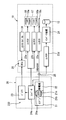
- 1 is an overall configuration diagram of a container refrigeration system according to a first embodiment.
- 1 is an external view of a vehicle equipped with a container refrigeration system according to a first embodiment. It is a refrigerating cycle figure which shows the flow of the refrigerant
- FIG. 1 shows the overall configuration of the container refrigeration system of the first embodiment.
- the container refrigeration system includes a power generation device 20 and a refrigeration device 10.
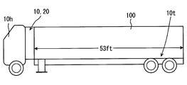
- FIG. 2 shows the outer shape of the vehicle, and
- FIG. 3 shows the configuration of the refrigeration cycle of the refrigeration apparatus 10.
- the refrigeration apparatus 10 of this embodiment includes an electric compressor 12, a condenser 13, an evaporator 15, a condenser fan 16, and an evaporator fan 17.
- the capacitor fan 16 is driven by the DC output of the DC power supply device 230 and blows air to the capacitor 13.
- the evaporator fan 17 is driven by the DC output of the DC power supply device 230 and blows air to the evaporator 15.
- the control device 30 controls the electric compressor 12, the condenser fan 16, and the evaporator fan 17.
- power generated by the power generator 20 is supplied to the refrigeration apparatus 10 for cooling the interior of the container 100.
- the power generation device 20 is driven by an engine 21 (also referred to as a sub-engine) that is different from the traveling engine that is a driving source of the vehicle.
- the refrigeration apparatus 10 is used in a vehicle that transports frozen food, fresh food, and the like as shown in FIG.
- This vehicle also called a refrigeration vehicle, is detachably connected to a driving vehicle (also referred to as a trailer head) 10h provided with a driver's cab and a traveling engine (not shown) and a trailer 10t provided with a container 100.
- the refrigeration apparatus 10 and the power generation apparatus 20 are integrally configured and attached to the front side of the container 100.
- the trailer 10t is pulled by the driving vehicle 10h.
- the refrigeration apparatus 10 includes a refrigerant circuit 11 configured in a closed circuit.
- a fixed capacity type electric compressor 12 a condenser (condenser) 13, an electronic expansion valve 14, and an evaporator (evaporator) 15 are connected in a loop through a refrigerant pipe in this order.
- a condenser fan 16 is provided adjacent to the condenser 13, and an evaporator fan 17 is provided adjacent to the evaporator 15.
- the refrigerant from the electric compressor 12 flows and dissipates heat to the outside air.
- the electric compressor 12 is a scroll type compressor.
- the condenser fan 16 takes air outside the container 100 (outside air) into the condenser 13.
- the evaporator fan 17 takes in the air (inside air) in the container 100 into the evaporator 15.
- the refrigerant circuit 11 has a vapor compression refrigeration cycle configured by circulating refrigerant. That is, in the refrigerant circuit 11, the refrigerant discharged from the electric compressor 12 is condensed by exchanging heat with the outside air by the condenser 13, decompressed by the electronic expansion valve 14, and then evaporated by exchanging heat with the inside air by the evaporator 15. To do. Thereby, the inside air is cooled.
- the amount of refrigerant discharged from the electric compressor 12 is adjusted by controlling the rotation speed of the electric compressor 12 by the inverter device 24 for driving the motor.
- the inverter device 24 is an inverter device for the electric compressor 12 and may be attached to the electric compressor 12.
- the power generation apparatus 20 supplies the refrigeration apparatus 10 with two independent outputs, that is, a 12 V class DC output and a three-phase 400 V class AC output to drive the refrigeration apparatus 10. is there.
- the power generation device 20 includes a power generation engine 21, which is also called a sub-engine, a generator 22, a battery 23, and an alternator 24b.
- the battery 23 is also necessary for starting the engine 21.
- the DC power supply device 230 that generates a DC output by the power of the engine 21 includes an alternator 24b driven by the engine 21 and a battery 23.
- the battery 23 is electrically connected to the alternator 24b.
- the battery 23 is charged with the direct current generated by the alternator 24b and stores the current.
- a starter 21a starts the engine 21.
- the stop solenoid 21b cuts off the fuel supplied to the engine 21 (fuel cut).
- the throttle control rod 21 c controls the throttle of the engine 21.
- the electric power of the battery 23 is supplied to the DC fan motor constituting the capacitor motor 10a via the contactor 23a for the capacitor motor 10a. With this electric power, the condenser fan 16 rotates. Moreover, the electric power from the battery 23 is supplied to the DC fan motor that constitutes the evaporator fan motor 10b via the contactor 23b for the evaporator fan motor 10b, and the evaporator fan 17 rotates.
- the three-phase 400V voltage generated by the generator 22 is also supplied to the electric heater 10c via the heater contactor 23c.
- the electric heater 10c a plurality of heaters are delta-connected. When the electromagnetic switch constituting the heater contactor 23c is opened, the electric heater 10c generates heat, and the internal temperature of the container 100 is adjusted and defrosting is performed during frosting.
- ECU which comprises the control apparatus 30 controls the contactors 23a, 23b and 23c which consist of electromagnetic switches, the control of the inverter apparatus 24, and the control of the engine 21.
- FIG. For example, the throttle control rod 21c is controlled by a command from the control device 30, and the rotational speed of the engine 21 is controlled.
- the DC output of the battery 23 is input to the control device 30.
- the rotation speed control device in the control device 30 drives the engine 21 at the calculated rotation speed.
- the rotation speed control device adjusts the fuel supply amount of the engine 21 by adjusting the throttle opening of the engine 21 with the throttle control rod 21c.
- the output of the inverter device 24 is regarded as the refrigeration load of the refrigeration apparatus 10.
- the inverter device 24 converts a three-phase 400V AC voltage and applies it to the DC brushless motor 24m of the electric compressor 12, and the speed of the electric compressor 12 using the DC brushless motor 24m is within a range of about 12 rps to 100 rps. Control.
- the control device 30 controls the refrigerant flow rate discharged from the electric compressor 12 based on the size of the refrigeration load of the refrigeration device 10.
- the control device 30 determines that the load of the power generation engine 21 is abnormal, the control device 30 decreases the output of the inverter device 24.
- the operation of the power generator 20 will be described.
- the power generator 22 and the alternator 24b generate power by using the power.
- the direct current output generated by the alternator 24 b is stored in the battery 23.
- the AC voltage output from the generator 22 is three-phase 400V.
- the AC output output from the generator 22 is converted into DC brushless motor driving power and output to the electric compressor 12.
- a DC output is output to the condenser fan 16 and the evaporator fan 17 by opening the electromagnetic switches of the contactor 23 a for the condenser motor 10 a and the contactor 23 b for the evaporator fan motor 10 b.
- the electric compressor 12 and the fans 16 and 17 are driven, and the vapor compression refrigeration cycle operates in the refrigerant circuit 11.
- the AC output output from the generator 22 is supplied to the contactor 23d for the electric compressor 12.
- the direct current output output from the alternator 24b is supplied via a battery 23 to a control device (ECU) 30, a contactor 23b for the evaporator fan motor 10b, and a contactor 23a for the capacitor motor 10a.
- ECU control device
- the inverter device 24, the electric compressor 12, the condenser fan 16, and the evaporator fan 17 are operated to keep the internal temperature at the target temperature.
- the power generation device 20 including the engine 21, the generator 22, the alternator 24b, and the battery 23 is controlled mainly via a starter 21a, a stop solenoid 21b, and a throttle control rod 21c based on a control signal from the control device 30.
- the evaporator fan motor 10b for driving the evaporator fan 17 needs to be controlled separately from the refrigeration load of the electric compressor 12. is there. Therefore, the evaporator fan motor 10b is controlled by the electric power supplied from the battery 23 instead of the generator 22.
- the engine speed during low-speed operation could only be reduced to 1500 rpm (50 Hz).
- the inverter device 24 in the refrigeration apparatus 10 since the inverter device 24 in the refrigeration apparatus 10 is used, an inverter that supplies power to the entire refrigeration apparatus is unnecessary.
- the rotational speed of the engine 21 can be widely controlled in accordance with the refrigeration load of the electric compressor 12. As a result, the engine speed during low-speed operation can be reduced to 1500 rpm or less.
- the fuel consumption of the engine 21 can be further reduced, and at the same time, the noise from the engine can be reduced.
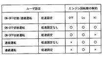
- FIG. 4 is a table showing what restrictions are imposed on the rotational speed of the engine 21 with respect to settings (user settings) determined by an operation signal from the control panel 31 by a user (for example, a driver). Note that the control panel 31 is disposed in the refrigeration apparatus 10.
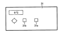
- FIG. 5 is a schematic diagram of the control panel 31.
- This continuous operation mode is set, for example, to stop vibrations generated by switching the engine on and off.
- the ON-OFF switching operation mode is set by the user using a push button switch constituting the continuous operation command unit 31b of FIG.
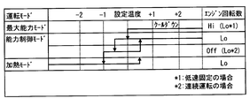
- FIG. 6 is a control chart showing the relationship between the temperature control of the refrigeration apparatus 10 and the control of the engine 21.
- the control of the engine 21 is performed in cooperation with the control of the refrigeration apparatus 10.
- the control of the refrigeration apparatus 10 first cools down the interior of the container 100 in the maximum capacity mode.
- the engine 21 is operated at a high speed (high rotation speed) (Hi) in principle.
- the low speed fixing is instructed, the engine 21 operates at a low speed (low rotation speed) (Low).
- the inverter device 24 sets the maximum number of revolutions of the electric compressor 12 within the output of the engine 21 to prevent engine stall.
- the capacity control mode is entered, and the internal temperature is controlled only by the rotation speed adjustment control of the electric compressor 12 by the inverter device 24. Since the electric compressor 12 operates at a low speed, the engine 21 operates at a low speed. At this time, by lowering the engine speed below 1500 rpm, the fuel consumption of the engine 21 is reduced and the noise is also reduced.
- the evaporator fan 17 that circulates the air in the container 100 has a separate power source from the electric compressor 12 and the electric heater 10c. Therefore, the evaporator fan 17 can be operated regardless of the rotational speed of the engine 21 and even when the engine 21 is stopped. As a result, the air inside the container 100 does not stagnate and the temperature inside the container can be made uniform.
- the electric compressor 12 can be stopped by controlling the inverter device 24 or shutting off the contactor 23d for the electric compressor 12.
- the refrigeration apparatus in the first embodiment includes the inverter device 24 and the electric compressor 12.
- An AC output from a generator 22 driven by the engine 21 is supplied to the inverter device.
- the refrigerant discharge amount of the electric compressor 12 is controlled by the inverter device 24. According to this, the rotation speed of the electric compressor 12 can be changed in a wide range.
- the inverter device 24 can be utilized without providing an inverter that converts the power supplied to the entire refrigeration apparatus 10.
- the capacitor fan 16 and the evaporator fan 17 can be driven regardless of the frequency and voltage of the AC output supplied by the generator 22.
- the refrigeration apparatus includes a control device 30 and a control panel 31 that supplies a command signal to the control device 30.
- a push button switch constituting a low speed fixing command unit 31a for fixing the rotational speed of the engine 21 to a low speed is provided as shown in FIG.
- the rotation speed of the engine 21 is fixed to a low speed by an operation signal from the control panel 31. As a result, it is possible to reduce the noise applied to the surroundings and operate the engine.
- the electric compressor 12 is provided in which the refrigerant discharge amount is controlled by the inverter device 24 to which the AC output from the generator 22 is supplied even if the rotational speed of the engine 21 is reduced. Therefore, the rotation speed of the electric compressor 12 can be controlled over a wide range.
- a DC power supply device 230 that generates a DC output from the power of the engine 21 is provided, and the capacitor fan 16 and the evaporator fan 17 can be driven by this DC output. Therefore, even if the rotational speed of the engine 21 is fixed at a low speed, the condenser fan 16 and the evaporator fan 17 can be driven at a high speed.
- the refrigeration apparatus has a control panel 31, and a push button switch constituting the continuous operation command unit 31b for continuously operating the engine without permitting the engine OFF (stop) is provided on the control panel 31 in FIG. Have.
- the engine 21 is set to the continuous operation mode, and an operation in which the vibration accompanying the ON-OFF switching of the engine 21 is suppressed can be performed. Furthermore, the capacitor fan 16 and the evaporator fan 17 of the present embodiment are driven by the DC power supply device 230. Accordingly, in both the ON-OFF switching operation mode and the continuous operation mode, the capacitor fan 16 and the evaporator fan are independent of the state of the engine 21 and the frequency and voltage of the AC output supplied to the inverter device 24. 17 can be controlled.
- the refrigeration apparatus 10 includes an electric heater 10 c that is heated by the AC output of the generator 22 and heats the interior of the container 100. According to this, the electric heater 10c heated by the alternating current output of the generator 22 can be energized for proper control of the internal temperature and for eliminating the frost in the internal storage of the container 100.
- the control device 30 of the refrigeration apparatus operates the engine 21 at a high speed (high rotation speed) or a low speed (low rotation speed). I am driving in. Further, when the electric compressor 12 is operated in the capacity control mode, the rotational speed of the engine 21 is set to a low speed. In addition, when the inverter device 24 is in the capacity control mode and the internal temperature is lowered from the set temperature to a predetermined temperature or lower, the rotational speed of the engine 21 is stopped (OFF) or low. In addition, the heating mode can be performed by energizing the electric heater 10c.
- the noise of the engine 21 is reduced and the speed of the electric compressor 12 is controlled by the inverter device 24.
- the internal temperature can be controlled.
- the rotational speed of the engine 21 is set to a high speed, and a sufficient alternating current output is supplied to the inverter device 24 so that the electric compressor 12 has a high capacity. Can drive.
- the engine 21 when the internal temperature becomes lower than the preset temperature by a predetermined temperature or more, the engine 21 is turned off (stopped) or is operated at a low rotation speed. Even in this case, the capacitor fan 16 and the evaporator fan 17 can be driven at sufficiently high rotation regardless of the frequency and voltage of the AC output supplied to the inverter device 24.
- the container refrigeration system includes a refrigeration apparatus 10 and a power generation apparatus 20 that supplies power to the refrigeration apparatus 10.
- the power generation device 20 has a DC power supply device 230 that generates a DC output by the power of the engine 21.
- the DC power supply device 230 includes an alternator 24b driven by engine power and a battery 23 charged by the alternator 24b. Therefore, according to the container refrigeration system of this embodiment equipped with the refrigeration apparatus 10, a stable DC low voltage can be supplied to the control device 30, the condenser fan 16, and the evaporator fan 17 via the battery 23. it can.
- the generator 22 driven by the engine 21 outputs a three-phase 400V AC voltage.
- the AC voltage output from the generator 22 is guided to an AC-DC converter (also simply referred to as a converter) 24a.
- the converter 24a outputs a DC voltage of 12V instead of the alternator 24b shown in FIG.
- the 12V DC voltage output from the battery 23 is guided to the control device 30. Further, the DC voltage of 12V is applied to the capacitor motor 10a and the evaporator fan motor 10b that drive the capacitor fan 16 and the evaporator fan 17 via the contactor 23a for the capacitor motor 10a and the contactor 23b for the evaporator fan motor 10b. Each is guided.
- the electric compressor 12 is a constant capacity type, the higher the number of revolutions, the greater the refrigerant discharge amount and the greater the refrigeration capacity.
- a variable capacity compressor can also be used. The capacity of the compressor and the operation of the inverter device 24 in this case are controlled based on a control signal from the control device 30.
- the DC power supply device 230 includes an AC-DC converter 24a that converts an AC output from the generator 22 into a DC output.
- a connection terminal 25 is provided on the output side of the generator 22, and power from a commercial power supply is supplied to the DC power supply device 230 via the connection terminal 25.
- the DC power supply device 230 having the converter 24a can generate a DC output by the commercial power source.
- the container refrigeration system mounted on the trailer has been described in the above embodiment, the container refrigeration system may be mounted on a truck. Moreover, although the container refrigeration system of the said embodiment is advantageous for a container of North American specification, it cannot be overemphasized that it can be used for a domestic use container.
- the refrigerant discharge amount of the electric compressor 12 is controlled by the rotational speed of the DC brushless motor 24m driven by the inverter device 24.
- capacity control may be used in combination using a variable capacity compressor.
Abstract
L'invention porte sur un dispositif frigorigène, lequel dispositif refroidit l'intérieur d'un contenant (100). Le dispositif frigorigène comprend un dispositif onduleur (24), un compresseur électrique (12), un condenseur (13), un évaporateur (15), un ventilateur de condenseur (16), un ventilateur d'évaporateur (17) et un dispositif de commande (30). Le dispositif onduleur est alimenté par un courant alternatif délivré en sortie à partir d'un générateur d'énergie (22) qui est entraîné par le moteur (21). En ce qui concerne le compresseur électrique, la quantité d'évacuation de fluide frigorigène est commandée par le dispositif onduleur. Le fluide frigorigène venant du compresseur électrique s'écoule dans le condenseur, après quoi le fluide frigorigène dissipe de la chaleur vers l'extérieur du contenant. Le fluide frigorigène venant du condenseur s'écoule dans l'évaporateur et refroidit l'intérieur du contenant. Le ventilateur de condenseur est actionné par la sortie en courant continu d'une source d'alimentation en courant continu (230), et souffle de l'air sur le condenseur. Le ventilateur d'évaporateur est actionné par la sortie en courant continu de la source d'alimentation en courant continu, et souffle de l'air sur l'évaporateur. Le dispositif de commande commande au moins le compresseur électrique, le dispositif onduleur et le moteur.
Priority Applications (4)
| Application Number | Priority Date | Filing Date | Title |
|---|---|---|---|
| EP15840042.4A EP3193104A4 (fr) | 2014-09-09 | 2015-08-28 | Dispositif frigorigène et système frigorigene de contenant |
| US15/505,940 US20180222278A1 (en) | 2014-09-09 | 2015-08-28 | Refrigeration device and container refrigeration system |
| CA2960462A CA2960462A1 (fr) | 2014-09-09 | 2015-08-28 | Dispositif frigorigene et systeme frigorigene de contenant |
| CN201580048179.0A CN106716028A (zh) | 2014-09-09 | 2015-08-28 | 制冷装置以及集装箱用制冷系统 |
Applications Claiming Priority (2)
| Application Number | Priority Date | Filing Date | Title |
|---|---|---|---|
| JP2014-183588 | 2014-09-09 | ||
| JP2014183588A JP2016056998A (ja) | 2014-09-09 | 2014-09-09 | 冷凍装置及びコンテナ用冷凍システム |
Publications (1)
| Publication Number | Publication Date |
|---|---|
| WO2016038838A1 true WO2016038838A1 (fr) | 2016-03-17 |
Family
ID=55458612
Family Applications (1)
| Application Number | Title | Priority Date | Filing Date |
|---|---|---|---|
| PCT/JP2015/004368 WO2016038838A1 (fr) | 2014-09-09 | 2015-08-28 | Dispositif frigorigène et système frigorigene de contenant |
Country Status (6)
| Country | Link |
|---|---|
| US (1) | US20180222278A1 (fr) |
| EP (1) | EP3193104A4 (fr) |
| JP (1) | JP2016056998A (fr) |
| CN (1) | CN106716028A (fr) |
| CA (1) | CA2960462A1 (fr) |
| WO (1) | WO2016038838A1 (fr) |
Cited By (18)
| Publication number | Priority date | Publication date | Assignee | Title |
|---|---|---|---|---|
| CN110573811A (zh) * | 2017-05-09 | 2019-12-13 | 株式会社电装 | 制冷装置 |
| JP2020143817A (ja) * | 2019-03-05 | 2020-09-10 | 三菱重工サーマルシステムズ株式会社 | 輸送用冷凍機械 |
| US10875497B2 (en) | 2018-10-31 | 2020-12-29 | Thermo King Corporation | Drive off protection system and method for preventing drive off |
| US10985511B2 (en) | 2019-09-09 | 2021-04-20 | Thermo King Corporation | Optimized power cord for transferring power to a transport climate control system |
| US11034213B2 (en) | 2018-09-29 | 2021-06-15 | Thermo King Corporation | Methods and systems for monitoring and displaying energy use and energy cost of a transport vehicle climate control system or a fleet of transport vehicle climate control systems |
| US11059352B2 (en) | 2018-10-31 | 2021-07-13 | Thermo King Corporation | Methods and systems for augmenting a vehicle powered transport climate control system |
| US11135894B2 (en) | 2019-09-09 | 2021-10-05 | Thermo King Corporation | System and method for managing power and efficiently sourcing a variable voltage for a transport climate control system |
| US11192451B2 (en) | 2018-09-19 | 2021-12-07 | Thermo King Corporation | Methods and systems for energy management of a transport climate control system |
| US11203262B2 (en) | 2019-09-09 | 2021-12-21 | Thermo King Corporation | Transport climate control system with an accessory power distribution unit for managing transport climate control loads |
| US11214118B2 (en) | 2019-09-09 | 2022-01-04 | Thermo King Corporation | Demand-side power distribution management for a plurality of transport climate control systems |
| US11260723B2 (en) | 2018-09-19 | 2022-03-01 | Thermo King Corporation | Methods and systems for power and load management of a transport climate control system |
| US11376922B2 (en) | 2019-09-09 | 2022-07-05 | Thermo King Corporation | Transport climate control system with a self-configuring matrix power converter |
| US11384967B2 (en) | 2017-10-05 | 2022-07-12 | Carrier Corporation | Multi power converter unit for a trailer refrigeration unit |
| US11420495B2 (en) | 2019-09-09 | 2022-08-23 | Thermo King Corporation | Interface system for connecting a vehicle and a transport climate control system |
| US11458802B2 (en) | 2019-09-09 | 2022-10-04 | Thermo King Corporation | Optimized power management for a transport climate control energy source |
| US11489431B2 (en) | 2019-12-30 | 2022-11-01 | Thermo King Corporation | Transport climate control system power architecture |
| US11695275B2 (en) | 2019-09-09 | 2023-07-04 | Thermo King Llc | Prioritized power delivery for facilitating transport climate control |
| US11794551B2 (en) | 2019-09-09 | 2023-10-24 | Thermo King Llc | Optimized power distribution to transport climate control systems amongst one or more electric supply equipment stations |
Families Citing this family (20)
| Publication number | Priority date | Publication date | Assignee | Title |
|---|---|---|---|---|
| WO2017088148A1 (fr) * | 2015-11-26 | 2017-06-01 | Dometic Sweden Ab | Appareil de refroidissement hybride |
| WO2017176725A1 (fr) | 2016-04-05 | 2017-10-12 | Carrier Corporation | Unité de réfrigération de transport sans moteur thermique |
| US10414241B2 (en) | 2016-06-30 | 2019-09-17 | Emerson Climate Technologies, Inc. | Systems and methods for capacity modulation through eutectic plates |
| US10569620B2 (en) | 2016-06-30 | 2020-02-25 | Emerson Climate Technologies, Inc. | Startup control systems and methods to reduce flooded startup conditions |
| EP3485209B1 (fr) * | 2016-07-14 | 2021-12-08 | Carrier Corporation | Système de réfrigération de transport et procédé de commande |
| JP6699621B2 (ja) * | 2017-05-26 | 2020-05-27 | 株式会社デンソー | 冷凍システム |
| JP2019124424A (ja) * | 2018-01-18 | 2019-07-25 | 株式会社デンソー | 冷凍装置 |
| CN108469127A (zh) * | 2018-04-12 | 2018-08-31 | 合肥天鹅制冷科技有限公司 | 在双制式输入电源时统一制冷系统及方法 |
| US11273684B2 (en) | 2018-09-29 | 2022-03-15 | Thermo King Corporation | Methods and systems for autonomous climate control optimization of a transport vehicle |
| US10870333B2 (en) | 2018-10-31 | 2020-12-22 | Thermo King Corporation | Reconfigurable utility power input with passive voltage booster |
| US10926610B2 (en) | 2018-10-31 | 2021-02-23 | Thermo King Corporation | Methods and systems for controlling a mild hybrid system that powers a transport climate control system |
| US11022451B2 (en) | 2018-11-01 | 2021-06-01 | Thermo King Corporation | Methods and systems for generation and utilization of supplemental stored energy for use in transport climate control |
| US11554638B2 (en) | 2018-12-28 | 2023-01-17 | Thermo King Llc | Methods and systems for preserving autonomous operation of a transport climate control system |
| US11072321B2 (en) | 2018-12-31 | 2021-07-27 | Thermo King Corporation | Systems and methods for smart load shedding of a transport vehicle while in transit |
| CN110203040B (zh) * | 2019-07-01 | 2024-01-12 | 合肥天鹅制冷科技有限公司 | 双制式双系统空调的控制系统 |
| US20210344252A1 (en) * | 2020-04-30 | 2021-11-04 | Thermo King Corporation | Three-phase generator with adaptive taps for use in a transport climate control system |
| EP4000976A1 (fr) * | 2020-11-19 | 2022-05-25 | Carrier Corporation | Unité de réfrigération de transport avec commande de réfrigération électrique à vitesse variable et source d'alimentation de générateur synchrone de moteur diesel à vitesse variable |
| CN112701374B (zh) * | 2020-12-16 | 2022-08-12 | 上海盈达空调设备股份有限公司 | 一种直流直驱集装箱电池组温度调节系统 |
| EP4082811A1 (fr) * | 2021-04-30 | 2022-11-02 | Thermo King Corporation | Commande de charge de moteur principal sur un ensemble de générateurs multi-vitesses |
| JP2023013766A (ja) * | 2021-07-16 | 2023-01-26 | トヨタ自動車株式会社 | 冷却ファン制御装置 |
Citations (9)
| Publication number | Priority date | Publication date | Assignee | Title |
|---|---|---|---|---|
| JPH03107675U (fr) * | 1990-02-16 | 1991-11-06 | ||
| JPH06146987A (ja) * | 1992-10-30 | 1994-05-27 | Sanyo Electric Co Ltd | エンジン駆動空調制御方法 |
| JPH10197123A (ja) * | 1997-01-10 | 1998-07-31 | Mitsubishi Heavy Ind Ltd | 輸送用冷凍装置 |
| JPH10201281A (ja) * | 1997-01-07 | 1998-07-31 | Mitsubishi Electric Corp | 空気調和装置 |
| JPH11304327A (ja) * | 1998-04-23 | 1999-11-05 | Matsushita Electric Ind Co Ltd | 車両用冷凍冷蔵装置 |
| JP2002081821A (ja) * | 2000-08-31 | 2002-03-22 | Mitsubishi Heavy Ind Ltd | 車載用冷凍装置 |
| US20110000244A1 (en) * | 2007-07-06 | 2011-01-06 | Carrier Corporation | Transport Refrigeration Series Hybrid Power Supply |
| WO2013165534A1 (fr) * | 2012-05-01 | 2013-11-07 | Carrier Corporation | Système de réfrigération de transport ayant des ventilateurs électriques |
| JP2014025593A (ja) * | 2012-07-24 | 2014-02-06 | Mitsubishi Heavy Ind Ltd | 輸送用冷凍システム |
Family Cites Families (5)
| Publication number | Priority date | Publication date | Assignee | Title |
|---|---|---|---|---|
| US6622505B2 (en) * | 2001-06-08 | 2003-09-23 | Thermo King Corporation | Alternator/invertor refrigeration unit |
| JP2007113874A (ja) * | 2005-10-21 | 2007-05-10 | Daikin Ind Ltd | トレーラー用冷凍装置 |
| US8381540B2 (en) * | 2006-11-15 | 2013-02-26 | Crosspoint Solutions, Llc | Installable HVAC systems for vehicles |
| EP2479515B1 (fr) * | 2009-09-16 | 2014-06-04 | Daikin Industries, Ltd. | Système frigorifique pour contenant |
| JP5893876B2 (ja) * | 2011-09-13 | 2016-03-23 | トヨタ自動車株式会社 | モータ制御システム |
-
2014
- 2014-09-09 JP JP2014183588A patent/JP2016056998A/ja active Pending
-
2015
- 2015-08-28 WO PCT/JP2015/004368 patent/WO2016038838A1/fr active Application Filing
- 2015-08-28 US US15/505,940 patent/US20180222278A1/en not_active Abandoned
- 2015-08-28 CA CA2960462A patent/CA2960462A1/fr not_active Abandoned
- 2015-08-28 CN CN201580048179.0A patent/CN106716028A/zh active Pending
- 2015-08-28 EP EP15840042.4A patent/EP3193104A4/fr not_active Withdrawn
Patent Citations (9)
| Publication number | Priority date | Publication date | Assignee | Title |
|---|---|---|---|---|
| JPH03107675U (fr) * | 1990-02-16 | 1991-11-06 | ||
| JPH06146987A (ja) * | 1992-10-30 | 1994-05-27 | Sanyo Electric Co Ltd | エンジン駆動空調制御方法 |
| JPH10201281A (ja) * | 1997-01-07 | 1998-07-31 | Mitsubishi Electric Corp | 空気調和装置 |
| JPH10197123A (ja) * | 1997-01-10 | 1998-07-31 | Mitsubishi Heavy Ind Ltd | 輸送用冷凍装置 |
| JPH11304327A (ja) * | 1998-04-23 | 1999-11-05 | Matsushita Electric Ind Co Ltd | 車両用冷凍冷蔵装置 |
| JP2002081821A (ja) * | 2000-08-31 | 2002-03-22 | Mitsubishi Heavy Ind Ltd | 車載用冷凍装置 |
| US20110000244A1 (en) * | 2007-07-06 | 2011-01-06 | Carrier Corporation | Transport Refrigeration Series Hybrid Power Supply |
| WO2013165534A1 (fr) * | 2012-05-01 | 2013-11-07 | Carrier Corporation | Système de réfrigération de transport ayant des ventilateurs électriques |
| JP2014025593A (ja) * | 2012-07-24 | 2014-02-06 | Mitsubishi Heavy Ind Ltd | 輸送用冷凍システム |
Non-Patent Citations (1)
| Title |
|---|
| See also references of EP3193104A4 * |
Cited By (23)
| Publication number | Priority date | Publication date | Assignee | Title |
|---|---|---|---|---|
| CN110573811A (zh) * | 2017-05-09 | 2019-12-13 | 株式会社电装 | 制冷装置 |
| CN110573811B (zh) * | 2017-05-09 | 2021-03-23 | 株式会社电装 | 制冷装置 |
| US11384967B2 (en) | 2017-10-05 | 2022-07-12 | Carrier Corporation | Multi power converter unit for a trailer refrigeration unit |
| US11192451B2 (en) | 2018-09-19 | 2021-12-07 | Thermo King Corporation | Methods and systems for energy management of a transport climate control system |
| US11260723B2 (en) | 2018-09-19 | 2022-03-01 | Thermo King Corporation | Methods and systems for power and load management of a transport climate control system |
| US11034213B2 (en) | 2018-09-29 | 2021-06-15 | Thermo King Corporation | Methods and systems for monitoring and displaying energy use and energy cost of a transport vehicle climate control system or a fleet of transport vehicle climate control systems |
| US10875497B2 (en) | 2018-10-31 | 2020-12-29 | Thermo King Corporation | Drive off protection system and method for preventing drive off |
| US11059352B2 (en) | 2018-10-31 | 2021-07-13 | Thermo King Corporation | Methods and systems for augmenting a vehicle powered transport climate control system |
| JP2020143817A (ja) * | 2019-03-05 | 2020-09-10 | 三菱重工サーマルシステムズ株式会社 | 輸送用冷凍機械 |
| JP7208063B2 (ja) | 2019-03-05 | 2023-01-18 | 三菱重工サーマルシステムズ株式会社 | 輸送用冷凍機械 |
| US11214118B2 (en) | 2019-09-09 | 2022-01-04 | Thermo King Corporation | Demand-side power distribution management for a plurality of transport climate control systems |
| US11203262B2 (en) | 2019-09-09 | 2021-12-21 | Thermo King Corporation | Transport climate control system with an accessory power distribution unit for managing transport climate control loads |
| US11376922B2 (en) | 2019-09-09 | 2022-07-05 | Thermo King Corporation | Transport climate control system with a self-configuring matrix power converter |
| US11135894B2 (en) | 2019-09-09 | 2021-10-05 | Thermo King Corporation | System and method for managing power and efficiently sourcing a variable voltage for a transport climate control system |
| US11420495B2 (en) | 2019-09-09 | 2022-08-23 | Thermo King Corporation | Interface system for connecting a vehicle and a transport climate control system |
| US11458802B2 (en) | 2019-09-09 | 2022-10-04 | Thermo King Corporation | Optimized power management for a transport climate control energy source |
| US10985511B2 (en) | 2019-09-09 | 2021-04-20 | Thermo King Corporation | Optimized power cord for transferring power to a transport climate control system |
| US11695275B2 (en) | 2019-09-09 | 2023-07-04 | Thermo King Llc | Prioritized power delivery for facilitating transport climate control |
| US11712943B2 (en) | 2019-09-09 | 2023-08-01 | Thermo King Llc | System and method for managing power and efficiently sourcing a variable voltage for a transport climate control system |
| US11794551B2 (en) | 2019-09-09 | 2023-10-24 | Thermo King Llc | Optimized power distribution to transport climate control systems amongst one or more electric supply equipment stations |
| US11827106B2 (en) | 2019-09-09 | 2023-11-28 | Thermo King Llc | Transport climate control system with an accessory power distribution unit for managing transport climate control loads |
| US11489431B2 (en) | 2019-12-30 | 2022-11-01 | Thermo King Corporation | Transport climate control system power architecture |
| US11843303B2 (en) | 2019-12-30 | 2023-12-12 | Thermo King Llc | Transport climate control system power architecture |
Also Published As
| Publication number | Publication date |
|---|---|
| CN106716028A (zh) | 2017-05-24 |
| EP3193104A4 (fr) | 2017-09-20 |
| CA2960462A1 (fr) | 2016-03-17 |
| JP2016056998A (ja) | 2016-04-21 |
| US20180222278A1 (en) | 2018-08-09 |
| EP3193104A1 (fr) | 2017-07-19 |
Similar Documents
| Publication | Publication Date | Title |
|---|---|---|
| WO2016038838A1 (fr) | Dispositif frigorigène et système frigorigene de contenant | |
| JP4325678B2 (ja) | 冷凍車両用冷凍装置 | |
| US7259469B2 (en) | Vehicle auxiliary power unit, assembly, and related methods | |
| EP2694304B1 (fr) | Système réfrigéré mobile semi-électrique | |
| JP5609470B2 (ja) | コンテナ用冷凍システム | |
| EP2668051B1 (fr) | Algorithme de commande efficace pour opération de démarrage-arrêt d'unité de réfrigération alimentée par un moteur | |
| KR102162926B1 (ko) | 냉장/냉동 탑차용 냉각 시스템 | |
| WO2012138500A1 (fr) | Système de réfrigération de transport et procédé pour son fonctionnement | |
| JP2007112357A (ja) | トレーラー用冷凍装置 | |
| US20050167090A1 (en) | Load management auxiliary power system | |
| JP2016535239A (ja) | 冷凍車両の冷凍システム | |
| KR20140087960A (ko) | 차량용 냉각장치 | |
| JP2003211950A (ja) | 車両用空気調和機 | |
| KR101186467B1 (ko) | 냉동, 냉장 및 온장 식품 운반용 차량의 전력 제어장치 및 방법 | |
| KR102162925B1 (ko) | 복수 압축기를 구비한 냉장/냉동 탑차용 냉각 시스템 | |
| JP4570127B2 (ja) | ヒートポンプ装置 | |
| KR101038671B1 (ko) | 냉동차량용 냉각장치 | |
| KR20090083543A (ko) | 고출력 발전기를 구비한 냉동차량용 냉동장치 | |
| JP2016121832A (ja) | 車載用冷凍装置 | |
| JP5404138B2 (ja) | エンジン駆動式冷凍装置 | |
| JPH0979727A (ja) | 冷凍冷蔵庫 | |
| JP5364527B2 (ja) | 定温輸送装置の加温運転方法および定温輸送装置 | |
| JP2004225991A (ja) | 車載用冷凍装置 | |
| CA2514433A1 (fr) | Systeme d'alimentation auxiliaire a gestion de charge | |
| JP2013002803A (ja) | トレーラ用冷凍装置 |
Legal Events
| Date | Code | Title | Description |
|---|---|---|---|
| 121 | Ep: the epo has been informed by wipo that ep was designated in this application |
Ref document number: 15840042 Country of ref document: EP Kind code of ref document: A1 |
|
| REEP | Request for entry into the european phase |
Ref document number: 2015840042 Country of ref document: EP |
|
| WWE | Wipo information: entry into national phase |
Ref document number: 15505940 Country of ref document: US |
|
| ENP | Entry into the national phase |
Ref document number: 2960462 Country of ref document: CA |
|
| NENP | Non-entry into the national phase |
Ref country code: DE |