WO2016038838A1 - Refrigerating device and container refrigerating system - Google Patents
Refrigerating device and container refrigerating system Download PDFInfo
- Publication number
- WO2016038838A1 WO2016038838A1 PCT/JP2015/004368 JP2015004368W WO2016038838A1 WO 2016038838 A1 WO2016038838 A1 WO 2016038838A1 JP 2015004368 W JP2015004368 W JP 2015004368W WO 2016038838 A1 WO2016038838 A1 WO 2016038838A1
- Authority
- WO
- WIPO (PCT)
- Prior art keywords
- engine
- container
- output
- electric compressor
- generator
- Prior art date
Links
Images


Classifications
-
- B—PERFORMING OPERATIONS; TRANSPORTING
- B60—VEHICLES IN GENERAL
- B60H—ARRANGEMENTS OF HEATING, COOLING, VENTILATING OR OTHER AIR-TREATING DEVICES SPECIALLY ADAPTED FOR PASSENGER OR GOODS SPACES OF VEHICLES
- B60H1/00—Heating, cooling or ventilating [HVAC] devices
- B60H1/00357—Air-conditioning arrangements specially adapted for particular vehicles
- B60H1/00364—Air-conditioning arrangements specially adapted for particular vehicles for caravans or trailers
-
- B—PERFORMING OPERATIONS; TRANSPORTING
- B60—VEHICLES IN GENERAL
- B60H—ARRANGEMENTS OF HEATING, COOLING, VENTILATING OR OTHER AIR-TREATING DEVICES SPECIALLY ADAPTED FOR PASSENGER OR GOODS SPACES OF VEHICLES
- B60H1/00—Heating, cooling or ventilating [HVAC] devices
- B60H1/00421—Driving arrangements for parts of a vehicle air-conditioning
- B60H1/00428—Driving arrangements for parts of a vehicle air-conditioning electric
-
- B—PERFORMING OPERATIONS; TRANSPORTING
- B60—VEHICLES IN GENERAL
- B60H—ARRANGEMENTS OF HEATING, COOLING, VENTILATING OR OTHER AIR-TREATING DEVICES SPECIALLY ADAPTED FOR PASSENGER OR GOODS SPACES OF VEHICLES
- B60H1/00—Heating, cooling or ventilating [HVAC] devices
- B60H1/00421—Driving arrangements for parts of a vehicle air-conditioning
- B60H1/0045—Driving arrangements for parts of a vehicle air-conditioning mechanical power take-offs from the vehicle propulsion unit
-
- B—PERFORMING OPERATIONS; TRANSPORTING
- B60—VEHICLES IN GENERAL
- B60H—ARRANGEMENTS OF HEATING, COOLING, VENTILATING OR OTHER AIR-TREATING DEVICES SPECIALLY ADAPTED FOR PASSENGER OR GOODS SPACES OF VEHICLES
- B60H1/00—Heating, cooling or ventilating [HVAC] devices
- B60H1/32—Cooling devices
- B60H1/3204—Cooling devices using compression
- B60H1/3205—Control means therefor
- B60H1/3208—Vehicle drive related control of the compressor drive means, e.g. for fuel saving purposes
-
- F—MECHANICAL ENGINEERING; LIGHTING; HEATING; WEAPONS; BLASTING
- F25—REFRIGERATION OR COOLING; COMBINED HEATING AND REFRIGERATION SYSTEMS; HEAT PUMP SYSTEMS; MANUFACTURE OR STORAGE OF ICE; LIQUEFACTION SOLIDIFICATION OF GASES
- F25B—REFRIGERATION MACHINES, PLANTS OR SYSTEMS; COMBINED HEATING AND REFRIGERATION SYSTEMS; HEAT PUMP SYSTEMS
- F25B27/00—Machines, plants or systems, using particular sources of energy
-
- F—MECHANICAL ENGINEERING; LIGHTING; HEATING; WEAPONS; BLASTING
- F25—REFRIGERATION OR COOLING; COMBINED HEATING AND REFRIGERATION SYSTEMS; HEAT PUMP SYSTEMS; MANUFACTURE OR STORAGE OF ICE; LIQUEFACTION SOLIDIFICATION OF GASES
- F25B—REFRIGERATION MACHINES, PLANTS OR SYSTEMS; COMBINED HEATING AND REFRIGERATION SYSTEMS; HEAT PUMP SYSTEMS
- F25B49/00—Arrangement or mounting of control or safety devices
- F25B49/02—Arrangement or mounting of control or safety devices for compression type machines, plants or systems
- F25B49/025—Motor control arrangements
-
- F—MECHANICAL ENGINEERING; LIGHTING; HEATING; WEAPONS; BLASTING
- F25—REFRIGERATION OR COOLING; COMBINED HEATING AND REFRIGERATION SYSTEMS; HEAT PUMP SYSTEMS; MANUFACTURE OR STORAGE OF ICE; LIQUEFACTION SOLIDIFICATION OF GASES
- F25D—REFRIGERATORS; COLD ROOMS; ICE-BOXES; COOLING OR FREEZING APPARATUS NOT OTHERWISE PROVIDED FOR
- F25D11/00—Self-contained movable devices, e.g. domestic refrigerators
-
- B—PERFORMING OPERATIONS; TRANSPORTING
- B60—VEHICLES IN GENERAL
- B60H—ARRANGEMENTS OF HEATING, COOLING, VENTILATING OR OTHER AIR-TREATING DEVICES SPECIALLY ADAPTED FOR PASSENGER OR GOODS SPACES OF VEHICLES
- B60H1/00—Heating, cooling or ventilating [HVAC] devices
- B60H1/32—Cooling devices
- B60H2001/3236—Cooling devices information from a variable is obtained
- B60H2001/3238—Cooling devices information from a variable is obtained related to the operation of the compressor
-
- B—PERFORMING OPERATIONS; TRANSPORTING
- B60—VEHICLES IN GENERAL
- B60H—ARRANGEMENTS OF HEATING, COOLING, VENTILATING OR OTHER AIR-TREATING DEVICES SPECIALLY ADAPTED FOR PASSENGER OR GOODS SPACES OF VEHICLES
- B60H1/00—Heating, cooling or ventilating [HVAC] devices
- B60H1/32—Cooling devices
- B60H2001/3269—Cooling devices output of a control signal
- B60H2001/327—Cooling devices output of a control signal related to a compressing unit
- B60H2001/3273—Cooling devices output of a control signal related to a compressing unit related to the operation of the vehicle, e.g. the compressor driving torque
-
- F—MECHANICAL ENGINEERING; LIGHTING; HEATING; WEAPONS; BLASTING
- F25—REFRIGERATION OR COOLING; COMBINED HEATING AND REFRIGERATION SYSTEMS; HEAT PUMP SYSTEMS; MANUFACTURE OR STORAGE OF ICE; LIQUEFACTION SOLIDIFICATION OF GASES
- F25B—REFRIGERATION MACHINES, PLANTS OR SYSTEMS; COMBINED HEATING AND REFRIGERATION SYSTEMS; HEAT PUMP SYSTEMS
- F25B2600/00—Control issues
- F25B2600/02—Compressor control
- F25B2600/021—Inverters therefor
-
- F—MECHANICAL ENGINEERING; LIGHTING; HEATING; WEAPONS; BLASTING
- F25—REFRIGERATION OR COOLING; COMBINED HEATING AND REFRIGERATION SYSTEMS; HEAT PUMP SYSTEMS; MANUFACTURE OR STORAGE OF ICE; LIQUEFACTION SOLIDIFICATION OF GASES
- F25B—REFRIGERATION MACHINES, PLANTS OR SYSTEMS; COMBINED HEATING AND REFRIGERATION SYSTEMS; HEAT PUMP SYSTEMS
- F25B2600/00—Control issues
- F25B2600/11—Fan speed control
- F25B2600/111—Fan speed control of condenser fans
-
- F—MECHANICAL ENGINEERING; LIGHTING; HEATING; WEAPONS; BLASTING
- F25—REFRIGERATION OR COOLING; COMBINED HEATING AND REFRIGERATION SYSTEMS; HEAT PUMP SYSTEMS; MANUFACTURE OR STORAGE OF ICE; LIQUEFACTION SOLIDIFICATION OF GASES
- F25B—REFRIGERATION MACHINES, PLANTS OR SYSTEMS; COMBINED HEATING AND REFRIGERATION SYSTEMS; HEAT PUMP SYSTEMS
- F25B2600/00—Control issues
- F25B2600/11—Fan speed control
- F25B2600/112—Fan speed control of evaporator fans
-
- H—ELECTRICITY
- H02—GENERATION; CONVERSION OR DISTRIBUTION OF ELECTRIC POWER
- H02P—CONTROL OR REGULATION OF ELECTRIC MOTORS, ELECTRIC GENERATORS OR DYNAMO-ELECTRIC CONVERTERS; CONTROLLING TRANSFORMERS, REACTORS OR CHOKE COILS
- H02P27/00—Arrangements or methods for the control of AC motors characterised by the kind of supply voltage
- H02P27/04—Arrangements or methods for the control of AC motors characterised by the kind of supply voltage using variable-frequency supply voltage, e.g. inverter or converter supply voltage
- H02P27/06—Arrangements or methods for the control of AC motors characterised by the kind of supply voltage using variable-frequency supply voltage, e.g. inverter or converter supply voltage using dc to ac converters or inverters
-
- Y—GENERAL TAGGING OF NEW TECHNOLOGICAL DEVELOPMENTS; GENERAL TAGGING OF CROSS-SECTIONAL TECHNOLOGIES SPANNING OVER SEVERAL SECTIONS OF THE IPC; TECHNICAL SUBJECTS COVERED BY FORMER USPC CROSS-REFERENCE ART COLLECTIONS [XRACs] AND DIGESTS
- Y02—TECHNOLOGIES OR APPLICATIONS FOR MITIGATION OR ADAPTATION AGAINST CLIMATE CHANGE
- Y02B—CLIMATE CHANGE MITIGATION TECHNOLOGIES RELATED TO BUILDINGS, e.g. HOUSING, HOUSE APPLIANCES OR RELATED END-USER APPLICATIONS
- Y02B30/00—Energy efficient heating, ventilation or air conditioning [HVAC]
- Y02B30/70—Efficient control or regulation technologies, e.g. for control of refrigerant flow, motor or heating
-
- Y—GENERAL TAGGING OF NEW TECHNOLOGICAL DEVELOPMENTS; GENERAL TAGGING OF CROSS-SECTIONAL TECHNOLOGIES SPANNING OVER SEVERAL SECTIONS OF THE IPC; TECHNICAL SUBJECTS COVERED BY FORMER USPC CROSS-REFERENCE ART COLLECTIONS [XRACs] AND DIGESTS
- Y02—TECHNOLOGIES OR APPLICATIONS FOR MITIGATION OR ADAPTATION AGAINST CLIMATE CHANGE
- Y02T—CLIMATE CHANGE MITIGATION TECHNOLOGIES RELATED TO TRANSPORTATION
- Y02T10/00—Road transport of goods or passengers
- Y02T10/80—Technologies aiming to reduce greenhouse gasses emissions common to all road transportation technologies
- Y02T10/88—Optimized components or subsystems, e.g. lighting, actively controlled glasses
Definitions
- the present disclosure relates to a refrigeration apparatus that cools the inside of a container, and a container refrigeration system including the refrigeration apparatus and a power generation apparatus.
- This trailer refrigeration apparatus does not include an inverter, and has an electric compressor driven using a three-phase induction motor.
- a blower such as a condenser fan motor in the refrigeration apparatus is also driven with the same three-phase output.
- this refrigeration apparatus can be driven only by a 50 Hz or 60 Hz AC power supply depending on the rating of the three-phase motor.
- Patent Document 1 by providing an inverter that supplies a variable frequency alternating current to the entire refrigeration apparatus, it is possible to widely control the engine speed according to the refrigeration load. Further, Patent Document 2 discloses a motor driving device and a refrigeration cycle device that drive a DC brushless motor using an inverter device for driving a motor.
- the present disclosure provides a refrigeration apparatus including an electric refrigerator that can prevent the inside air of the container from stagnating even if the rotational speed of the electric compressor is reduced, and a refrigeration apparatus. It aims at providing the refrigeration system for containers provided with the electric power generating apparatus.
- the refrigeration apparatus of the present disclosure cools the inside of the container (100).
- the refrigeration apparatus includes an inverter device for driving a motor, an electric compressor, a condenser, an evaporator, a condenser fan, an evaporator fan, and a control device.
- the inverter device is supplied with AC output from a generator driven by the engine.
- the electric compressor the refrigerant discharge amount is controlled by the inverter device.
- the refrigerant from the electric compressor flows inside, and dissipates the refrigerant to the outside air outside the container.
- the evaporator the refrigerant from the condenser flows inside and cools the inside of the container.
- the capacitor fan is driven by the DC output of the DC power supply device and blows air to the capacitor.
- the evaporator fan is driven by the DC output of the DC power supply device and blows air to the evaporator.
- the control device controls at least the electric compressor, the inverter device, and the engine.
- the refrigerating apparatus includes the electric compressor whose refrigerant discharge amount is controlled by the inverter device to which the AC output of the generator is supplied. Therefore, the rotational speed of the electric compressor can be changed regardless of the rotational speed of the engine. Therefore, even when the refrigeration load is light, the engine speed can be reduced, and fuel consumption can be reduced. Further, a DC power supply of a different system from the AC output supplied by the generator is supplied. Thereby, a capacitor
- the container refrigeration system of the present disclosure includes a refrigeration apparatus that cools the inside of the container, and a power generation apparatus that supplies electric power to the refrigeration apparatus.
- the power generation device includes an engine, a generator, and a DC power supply device.
- the generator is driven by the engine and generates an alternating current output.
- the direct current power supply device generates direct current output by converting engine power into electric power.
- the container refrigeration system of the present disclosure includes an electric compressor whose refrigerant discharge amount is controlled by an inverter device to which an AC output from a generator is supplied. Therefore, the rotational speed of the electric compressor can be changed over a wide range regardless of the rotational speed of the engine. Therefore, the engine speed can be reduced even when the refrigeration load is light, and fuel consumption can be saved.
- a DC power supply device of a system different from the AC output supplied by the generator is provided. Therefore, the capacitor fan and the evaporator fan can be driven regardless of the frequency and voltage of the generator output.
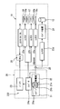
- 1 is an overall configuration diagram of a container refrigeration system according to a first embodiment.
- 1 is an external view of a vehicle equipped with a container refrigeration system according to a first embodiment. It is a refrigerating cycle figure which shows the flow of the refrigerant
- FIG. 1 shows the overall configuration of the container refrigeration system of the first embodiment.
- the container refrigeration system includes a power generation device 20 and a refrigeration device 10.
- FIG. 2 shows the outer shape of the vehicle, and
- FIG. 3 shows the configuration of the refrigeration cycle of the refrigeration apparatus 10.
- the refrigeration apparatus 10 of this embodiment includes an electric compressor 12, a condenser 13, an evaporator 15, a condenser fan 16, and an evaporator fan 17.
- the capacitor fan 16 is driven by the DC output of the DC power supply device 230 and blows air to the capacitor 13.
- the evaporator fan 17 is driven by the DC output of the DC power supply device 230 and blows air to the evaporator 15.
- the control device 30 controls the electric compressor 12, the condenser fan 16, and the evaporator fan 17.
- power generated by the power generator 20 is supplied to the refrigeration apparatus 10 for cooling the interior of the container 100.
- the power generation device 20 is driven by an engine 21 (also referred to as a sub-engine) that is different from the traveling engine that is a driving source of the vehicle.
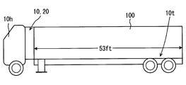
- the refrigeration apparatus 10 is used in a vehicle that transports frozen food, fresh food, and the like as shown in FIG.
- This vehicle also called a refrigeration vehicle, is detachably connected to a driving vehicle (also referred to as a trailer head) 10h provided with a driver's cab and a traveling engine (not shown) and a trailer 10t provided with a container 100.
- the refrigeration apparatus 10 and the power generation apparatus 20 are integrally configured and attached to the front side of the container 100.
- the trailer 10t is pulled by the driving vehicle 10h.
- the refrigeration apparatus 10 includes a refrigerant circuit 11 configured in a closed circuit.
- a fixed capacity type electric compressor 12 a condenser (condenser) 13, an electronic expansion valve 14, and an evaporator (evaporator) 15 are connected in a loop through a refrigerant pipe in this order.
- a condenser fan 16 is provided adjacent to the condenser 13, and an evaporator fan 17 is provided adjacent to the evaporator 15.
- the refrigerant from the electric compressor 12 flows and dissipates heat to the outside air.
- the electric compressor 12 is a scroll type compressor.
- the condenser fan 16 takes air outside the container 100 (outside air) into the condenser 13.
- the evaporator fan 17 takes in the air (inside air) in the container 100 into the evaporator 15.
- the refrigerant circuit 11 has a vapor compression refrigeration cycle configured by circulating refrigerant. That is, in the refrigerant circuit 11, the refrigerant discharged from the electric compressor 12 is condensed by exchanging heat with the outside air by the condenser 13, decompressed by the electronic expansion valve 14, and then evaporated by exchanging heat with the inside air by the evaporator 15. To do. Thereby, the inside air is cooled.
- the amount of refrigerant discharged from the electric compressor 12 is adjusted by controlling the rotation speed of the electric compressor 12 by the inverter device 24 for driving the motor.
- the inverter device 24 is an inverter device for the electric compressor 12 and may be attached to the electric compressor 12.
- the power generation apparatus 20 supplies the refrigeration apparatus 10 with two independent outputs, that is, a 12 V class DC output and a three-phase 400 V class AC output to drive the refrigeration apparatus 10. is there.
- the power generation device 20 includes a power generation engine 21, which is also called a sub-engine, a generator 22, a battery 23, and an alternator 24b.
- the battery 23 is also necessary for starting the engine 21.
- the DC power supply device 230 that generates a DC output by the power of the engine 21 includes an alternator 24b driven by the engine 21 and a battery 23.
- the battery 23 is electrically connected to the alternator 24b.
- the battery 23 is charged with the direct current generated by the alternator 24b and stores the current.
- a starter 21a starts the engine 21.
- the stop solenoid 21b cuts off the fuel supplied to the engine 21 (fuel cut).
- the throttle control rod 21 c controls the throttle of the engine 21.
- the electric power of the battery 23 is supplied to the DC fan motor constituting the capacitor motor 10a via the contactor 23a for the capacitor motor 10a. With this electric power, the condenser fan 16 rotates. Moreover, the electric power from the battery 23 is supplied to the DC fan motor that constitutes the evaporator fan motor 10b via the contactor 23b for the evaporator fan motor 10b, and the evaporator fan 17 rotates.
- the three-phase 400V voltage generated by the generator 22 is also supplied to the electric heater 10c via the heater contactor 23c.
- the electric heater 10c a plurality of heaters are delta-connected. When the electromagnetic switch constituting the heater contactor 23c is opened, the electric heater 10c generates heat, and the internal temperature of the container 100 is adjusted and defrosting is performed during frosting.
- ECU which comprises the control apparatus 30 controls the contactors 23a, 23b and 23c which consist of electromagnetic switches, the control of the inverter apparatus 24, and the control of the engine 21.
- FIG. For example, the throttle control rod 21c is controlled by a command from the control device 30, and the rotational speed of the engine 21 is controlled.
- the DC output of the battery 23 is input to the control device 30.
- the rotation speed control device in the control device 30 drives the engine 21 at the calculated rotation speed.
- the rotation speed control device adjusts the fuel supply amount of the engine 21 by adjusting the throttle opening of the engine 21 with the throttle control rod 21c.
- the output of the inverter device 24 is regarded as the refrigeration load of the refrigeration apparatus 10.
- the inverter device 24 converts a three-phase 400V AC voltage and applies it to the DC brushless motor 24m of the electric compressor 12, and the speed of the electric compressor 12 using the DC brushless motor 24m is within a range of about 12 rps to 100 rps. Control.
- the control device 30 controls the refrigerant flow rate discharged from the electric compressor 12 based on the size of the refrigeration load of the refrigeration device 10.
- the control device 30 determines that the load of the power generation engine 21 is abnormal, the control device 30 decreases the output of the inverter device 24.
- the operation of the power generator 20 will be described.
- the power generator 22 and the alternator 24b generate power by using the power.
- the direct current output generated by the alternator 24 b is stored in the battery 23.
- the AC voltage output from the generator 22 is three-phase 400V.
- the AC output output from the generator 22 is converted into DC brushless motor driving power and output to the electric compressor 12.
- a DC output is output to the condenser fan 16 and the evaporator fan 17 by opening the electromagnetic switches of the contactor 23 a for the condenser motor 10 a and the contactor 23 b for the evaporator fan motor 10 b.
- the electric compressor 12 and the fans 16 and 17 are driven, and the vapor compression refrigeration cycle operates in the refrigerant circuit 11.
- the AC output output from the generator 22 is supplied to the contactor 23d for the electric compressor 12.
- the direct current output output from the alternator 24b is supplied via a battery 23 to a control device (ECU) 30, a contactor 23b for the evaporator fan motor 10b, and a contactor 23a for the capacitor motor 10a.
- ECU control device
- the inverter device 24, the electric compressor 12, the condenser fan 16, and the evaporator fan 17 are operated to keep the internal temperature at the target temperature.
- the power generation device 20 including the engine 21, the generator 22, the alternator 24b, and the battery 23 is controlled mainly via a starter 21a, a stop solenoid 21b, and a throttle control rod 21c based on a control signal from the control device 30.
- the evaporator fan motor 10b for driving the evaporator fan 17 needs to be controlled separately from the refrigeration load of the electric compressor 12. is there. Therefore, the evaporator fan motor 10b is controlled by the electric power supplied from the battery 23 instead of the generator 22.
- the engine speed during low-speed operation could only be reduced to 1500 rpm (50 Hz).
- the inverter device 24 in the refrigeration apparatus 10 since the inverter device 24 in the refrigeration apparatus 10 is used, an inverter that supplies power to the entire refrigeration apparatus is unnecessary.
- the rotational speed of the engine 21 can be widely controlled in accordance with the refrigeration load of the electric compressor 12. As a result, the engine speed during low-speed operation can be reduced to 1500 rpm or less.
- the fuel consumption of the engine 21 can be further reduced, and at the same time, the noise from the engine can be reduced.
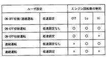
- FIG. 4 is a table showing what restrictions are imposed on the rotational speed of the engine 21 with respect to settings (user settings) determined by an operation signal from the control panel 31 by a user (for example, a driver). Note that the control panel 31 is disposed in the refrigeration apparatus 10.
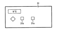
- FIG. 5 is a schematic diagram of the control panel 31.
- This continuous operation mode is set, for example, to stop vibrations generated by switching the engine on and off.
- the ON-OFF switching operation mode is set by the user using a push button switch constituting the continuous operation command unit 31b of FIG.
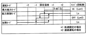
- FIG. 6 is a control chart showing the relationship between the temperature control of the refrigeration apparatus 10 and the control of the engine 21.
- the control of the engine 21 is performed in cooperation with the control of the refrigeration apparatus 10.
- the control of the refrigeration apparatus 10 first cools down the interior of the container 100 in the maximum capacity mode.
- the engine 21 is operated at a high speed (high rotation speed) (Hi) in principle.
- the low speed fixing is instructed, the engine 21 operates at a low speed (low rotation speed) (Low).
- the inverter device 24 sets the maximum number of revolutions of the electric compressor 12 within the output of the engine 21 to prevent engine stall.
- the capacity control mode is entered, and the internal temperature is controlled only by the rotation speed adjustment control of the electric compressor 12 by the inverter device 24. Since the electric compressor 12 operates at a low speed, the engine 21 operates at a low speed. At this time, by lowering the engine speed below 1500 rpm, the fuel consumption of the engine 21 is reduced and the noise is also reduced.
- the evaporator fan 17 that circulates the air in the container 100 has a separate power source from the electric compressor 12 and the electric heater 10c. Therefore, the evaporator fan 17 can be operated regardless of the rotational speed of the engine 21 and even when the engine 21 is stopped. As a result, the air inside the container 100 does not stagnate and the temperature inside the container can be made uniform.
- the electric compressor 12 can be stopped by controlling the inverter device 24 or shutting off the contactor 23d for the electric compressor 12.
- the refrigeration apparatus in the first embodiment includes the inverter device 24 and the electric compressor 12.
- An AC output from a generator 22 driven by the engine 21 is supplied to the inverter device.
- the refrigerant discharge amount of the electric compressor 12 is controlled by the inverter device 24. According to this, the rotation speed of the electric compressor 12 can be changed in a wide range.
- the inverter device 24 can be utilized without providing an inverter that converts the power supplied to the entire refrigeration apparatus 10.
- the capacitor fan 16 and the evaporator fan 17 can be driven regardless of the frequency and voltage of the AC output supplied by the generator 22.
- the refrigeration apparatus includes a control device 30 and a control panel 31 that supplies a command signal to the control device 30.
- a push button switch constituting a low speed fixing command unit 31a for fixing the rotational speed of the engine 21 to a low speed is provided as shown in FIG.
- the rotation speed of the engine 21 is fixed to a low speed by an operation signal from the control panel 31. As a result, it is possible to reduce the noise applied to the surroundings and operate the engine.
- the electric compressor 12 is provided in which the refrigerant discharge amount is controlled by the inverter device 24 to which the AC output from the generator 22 is supplied even if the rotational speed of the engine 21 is reduced. Therefore, the rotation speed of the electric compressor 12 can be controlled over a wide range.
- a DC power supply device 230 that generates a DC output from the power of the engine 21 is provided, and the capacitor fan 16 and the evaporator fan 17 can be driven by this DC output. Therefore, even if the rotational speed of the engine 21 is fixed at a low speed, the condenser fan 16 and the evaporator fan 17 can be driven at a high speed.
- the refrigeration apparatus has a control panel 31, and a push button switch constituting the continuous operation command unit 31b for continuously operating the engine without permitting the engine OFF (stop) is provided on the control panel 31 in FIG. Have.
- the engine 21 is set to the continuous operation mode, and an operation in which the vibration accompanying the ON-OFF switching of the engine 21 is suppressed can be performed. Furthermore, the capacitor fan 16 and the evaporator fan 17 of the present embodiment are driven by the DC power supply device 230. Accordingly, in both the ON-OFF switching operation mode and the continuous operation mode, the capacitor fan 16 and the evaporator fan are independent of the state of the engine 21 and the frequency and voltage of the AC output supplied to the inverter device 24. 17 can be controlled.
- the refrigeration apparatus 10 includes an electric heater 10 c that is heated by the AC output of the generator 22 and heats the interior of the container 100. According to this, the electric heater 10c heated by the alternating current output of the generator 22 can be energized for proper control of the internal temperature and for eliminating the frost in the internal storage of the container 100.
- the control device 30 of the refrigeration apparatus operates the engine 21 at a high speed (high rotation speed) or a low speed (low rotation speed). I am driving in. Further, when the electric compressor 12 is operated in the capacity control mode, the rotational speed of the engine 21 is set to a low speed. In addition, when the inverter device 24 is in the capacity control mode and the internal temperature is lowered from the set temperature to a predetermined temperature or lower, the rotational speed of the engine 21 is stopped (OFF) or low. In addition, the heating mode can be performed by energizing the electric heater 10c.
- the noise of the engine 21 is reduced and the speed of the electric compressor 12 is controlled by the inverter device 24.
- the internal temperature can be controlled.
- the rotational speed of the engine 21 is set to a high speed, and a sufficient alternating current output is supplied to the inverter device 24 so that the electric compressor 12 has a high capacity. Can drive.
- the engine 21 when the internal temperature becomes lower than the preset temperature by a predetermined temperature or more, the engine 21 is turned off (stopped) or is operated at a low rotation speed. Even in this case, the capacitor fan 16 and the evaporator fan 17 can be driven at sufficiently high rotation regardless of the frequency and voltage of the AC output supplied to the inverter device 24.
- the container refrigeration system includes a refrigeration apparatus 10 and a power generation apparatus 20 that supplies power to the refrigeration apparatus 10.
- the power generation device 20 has a DC power supply device 230 that generates a DC output by the power of the engine 21.
- the DC power supply device 230 includes an alternator 24b driven by engine power and a battery 23 charged by the alternator 24b. Therefore, according to the container refrigeration system of this embodiment equipped with the refrigeration apparatus 10, a stable DC low voltage can be supplied to the control device 30, the condenser fan 16, and the evaporator fan 17 via the battery 23. it can.
- the generator 22 driven by the engine 21 outputs a three-phase 400V AC voltage.
- the AC voltage output from the generator 22 is guided to an AC-DC converter (also simply referred to as a converter) 24a.
- the converter 24a outputs a DC voltage of 12V instead of the alternator 24b shown in FIG.
- the 12V DC voltage output from the battery 23 is guided to the control device 30. Further, the DC voltage of 12V is applied to the capacitor motor 10a and the evaporator fan motor 10b that drive the capacitor fan 16 and the evaporator fan 17 via the contactor 23a for the capacitor motor 10a and the contactor 23b for the evaporator fan motor 10b. Each is guided.
- the electric compressor 12 is a constant capacity type, the higher the number of revolutions, the greater the refrigerant discharge amount and the greater the refrigeration capacity.
- a variable capacity compressor can also be used. The capacity of the compressor and the operation of the inverter device 24 in this case are controlled based on a control signal from the control device 30.
- the DC power supply device 230 includes an AC-DC converter 24a that converts an AC output from the generator 22 into a DC output.
- a connection terminal 25 is provided on the output side of the generator 22, and power from a commercial power supply is supplied to the DC power supply device 230 via the connection terminal 25.
- the DC power supply device 230 having the converter 24a can generate a DC output by the commercial power source.
- the container refrigeration system mounted on the trailer has been described in the above embodiment, the container refrigeration system may be mounted on a truck. Moreover, although the container refrigeration system of the said embodiment is advantageous for a container of North American specification, it cannot be overemphasized that it can be used for a domestic use container.
- the refrigerant discharge amount of the electric compressor 12 is controlled by the rotational speed of the DC brushless motor 24m driven by the inverter device 24.
- capacity control may be used in combination using a variable capacity compressor.
Abstract
A refrigerating device cools the interior of a container (100). The refrigerating device comprises an inverter device (24), an electric compressor (12), a condenser (13), an evaporator (15), a condenser fan (16), an evaporator fan (17), and a control device (30). The inverter device is supplied with alternating current output from a power generator (22) that is driven by an engine (21). In terms of the electric compressor, the amount of refrigerant discharge is controlled by the inverter device. The refrigerant from the electric compressor flows into the condenser and then the refrigerant dissipates heat to the air outside of the container. The refrigerant from the condenser flows into the evaporator and cools the interior of the container. The condenser fan is driven by the direct current output of a direct current power source (230) and blows air onto the condenser. The evaporator fan is driven by the direct current output of the direct current power source and blows air onto the evaporator. The control device controls at least the electric compressor, the inverter device, and the engine.
Description
本出願は、当該開示内容が参照によって本出願に組み込まれた、2014年9月9日に出願された日本特許出願2014-183588号を基にしている。
This application is based on Japanese Patent Application No. 2014-183588 filed on September 9, 2014, the disclosure of which is incorporated herein by reference.
本開示は、コンテナの庫内を冷却する冷凍装置、及び、この冷凍装置と発電装置とを備えたコンテナ用冷凍システムに関するものである。
The present disclosure relates to a refrigeration apparatus that cools the inside of a container, and a container refrigeration system including the refrigeration apparatus and a power generation apparatus.
発電機によって発電された電力を用いて冷凍装置を駆動するコンテナ用冷凍システムを備えたトレーラが実用化されている。このトレーラの冷凍装置は、インバータを備えておらず、三相誘導モータを使用して駆動される電動圧縮機を有している。冷凍装置内のコンデンサファンモータ等の送風機も同じ三相出力で駆動される。しかし、この冷凍装置では、三相モータの定格に応じて、50Hz又は60Hzの交流電源でしか駆動できない。
Trailers equipped with a container refrigeration system that drives a refrigeration system using electric power generated by a generator have been put into practical use. This trailer refrigeration apparatus does not include an inverter, and has an electric compressor driven using a three-phase induction motor. A blower such as a condenser fan motor in the refrigeration apparatus is also driven with the same three-phase output. However, this refrigeration apparatus can be driven only by a 50 Hz or 60 Hz AC power supply depending on the rating of the three-phase motor.
そのため、冷凍装置への電力供給は、50Hz~60Hzの周波数で電力を供給する必要がある。よって、発電機用エンジンの回転数にも制約がある。つまり、電動圧縮機に三相4極モータを採用した場合は、エンジン回転数は、1500rpm~1800rpm程度に限られてしまう。
Therefore, it is necessary to supply power to the refrigeration apparatus at a frequency of 50 Hz to 60 Hz. Therefore, there is a restriction on the rotational speed of the generator engine. That is, when a three-phase four-pole motor is adopted for the electric compressor, the engine speed is limited to about 1500 rpm to 1800 rpm.
この場合、冷凍負荷が軽いため、更にエンジン出力を低下させたくても、エンジン回転数の下限が1500rpmであると、エンジン出力を低下させることができない。そのため、エンジンの燃費効率が低下する恐れがある。
In this case, since the refrigeration load is light, even if it is desired to further reduce the engine output, if the lower limit of the engine speed is 1500 rpm, the engine output cannot be reduced. As a result, the fuel efficiency of the engine may be reduced.
特許文献1では、冷凍装置全体に可変周波数の交流を供給するインバータを設けることで、エンジン回転数を冷凍負荷に合わせて幅広く制御することを可能としている。さらに、特許文献2では、モータ駆動用のインバータ装置を用いて直流ブラシレスモータを駆動する電動機の駆動装置、及び冷凍サイクル装置を開示している。
In Patent Document 1, by providing an inverter that supplies a variable frequency alternating current to the entire refrigeration apparatus, it is possible to widely control the engine speed according to the refrigeration load. Further, Patent Document 2 discloses a motor driving device and a refrigeration cycle device that drive a DC brushless motor using an inverter device for driving a motor.
上記特許文献1の冷凍サイクル装置は、発電用エンジン、コンバータ、インバータ、および制御装置を備えている。コンバータは、発電機で発電された交流出力を直流出力に変換。インバータは、その直流出力を交流出力に変換して冷凍装置全体に交流出力を供給する。制御装置は、冷凍装置の冷凍負荷の大きさに基づいて発電用エンジンの回転数を制御する。
The refrigeration cycle apparatus of Patent Document 1 includes a power generation engine, a converter, an inverter, and a control device. The converter converts the AC output generated by the generator into DC output. The inverter converts the direct current output into an alternating current output and supplies the alternating current output to the entire refrigeration apparatus. The control device controls the rotational speed of the power generation engine based on the size of the refrigeration load of the refrigeration device.
しかしながら、インバータで電動圧縮機の回転数を低下させると、コンテナ内部の内気を循環させるエバポレータファンモータの回転数も低下してしまう。よって、特に長さが53フィートもある北米仕様のトレーラの場合は、内気の流れがショートサーキットを循環し、顕著に内気が澱んでしまう。
However, when the rotation speed of the electric compressor is reduced by the inverter, the rotation speed of the evaporator fan motor that circulates the inside air inside the container also decreases. Therefore, especially in the case of a North American specification trailer having a length of 53 feet, the flow of the inside air circulates through the short circuit, and the inside air becomes noticeably stagnant.
本開示は、上記問題点に鑑み、電動圧縮機の回転数を低くしても、コンテナ内部の内気が澱んでしまうことを防ぐことができる電動冷凍機を備えた冷凍装置、及び、冷凍装置と発電装置を備えたコンテナ用冷凍システムを提供することを目的とする。
In view of the above problems, the present disclosure provides a refrigeration apparatus including an electric refrigerator that can prevent the inside air of the container from stagnating even if the rotational speed of the electric compressor is reduced, and a refrigeration apparatus. It aims at providing the refrigeration system for containers provided with the electric power generating apparatus.
本開示の冷凍装置は、コンテナ(100)の庫内を冷却する。冷凍装置は、モータ駆動用のインバータ装置と、電動圧縮機と、コンデンサと、エバポレータと、コンデンサファンと、エバポレータファンと、制御装置と、を備える。インバータ装置は、エンジンによって駆動される発電機からの交流出力が供給される。電動圧縮機は、インバータ装置によって冷媒吐出量が制御される。コンデンサは、電動圧縮機からの冷媒が内部を流れ、冷媒をコンテナ外部の外気に放熱させる。エバポレータは、コンデンサからの冷媒が内部を流れ、コンテナの庫内を冷却する。コンデンサファンは、直流電源装置の直流出力により駆動され、コンデンサに送風する。エバポレータファンは、直流電源装置の直流出力により駆動され、エバポレータに送風する。制御装置は、少なくとも電動圧縮機、インバータ装置、およびエンジンを制御する。
The refrigeration apparatus of the present disclosure cools the inside of the container (100). The refrigeration apparatus includes an inverter device for driving a motor, an electric compressor, a condenser, an evaporator, a condenser fan, an evaporator fan, and a control device. The inverter device is supplied with AC output from a generator driven by the engine. In the electric compressor, the refrigerant discharge amount is controlled by the inverter device. In the condenser, the refrigerant from the electric compressor flows inside, and dissipates the refrigerant to the outside air outside the container. In the evaporator, the refrigerant from the condenser flows inside and cools the inside of the container. The capacitor fan is driven by the DC output of the DC power supply device and blows air to the capacitor. The evaporator fan is driven by the DC output of the DC power supply device and blows air to the evaporator. The control device controls at least the electric compressor, the inverter device, and the engine.
本開示の冷凍装置によれば、発電機の交流出力が供給されるインバータ装置によって冷媒吐出量を制御される電動圧縮機を備える。したがって、エンジンの回転数にかかわらず電動圧縮機の回転数を変えることができる。そのため、冷凍負荷が軽いときであってもエンジンの回転数を下げることができ、燃料消費量を削減できる。また、発電機が供給する交流出力とは別系統の直流電源が供給される。これにより、発電機出力の周波数及び電圧に関係なくコンデンサファン及びエバポレータファンを駆動することができる。
The refrigerating apparatus according to the present disclosure includes the electric compressor whose refrigerant discharge amount is controlled by the inverter device to which the AC output of the generator is supplied. Therefore, the rotational speed of the electric compressor can be changed regardless of the rotational speed of the engine. Therefore, even when the refrigeration load is light, the engine speed can be reduced, and fuel consumption can be reduced. Further, a DC power supply of a different system from the AC output supplied by the generator is supplied. Thereby, a capacitor | condenser fan and an evaporator fan can be driven irrespective of the frequency and voltage of a generator output.
本開示のコンテナ用冷凍システムは、コンテナの庫内を冷却する冷凍装置と、冷凍装置に電力を供給する発電装置とを備えている。
The container refrigeration system of the present disclosure includes a refrigeration apparatus that cools the inside of the container, and a power generation apparatus that supplies electric power to the refrigeration apparatus.
発電装置は、エンジンと、発電機と、直流電源装置と、を含む。発電機は、エンジンによって駆動され交流出力を発生する。直流電源装置は、エンジンの動力が電力に変換されて直流出力を発生する。
The power generation device includes an engine, a generator, and a DC power supply device. The generator is driven by the engine and generates an alternating current output. The direct current power supply device generates direct current output by converting engine power into electric power.
冷凍装置は、モータ駆動用のインバータ装置と、電動圧縮機と、コンデンサと、エバポレータと、コンデンサファンと、エバポレータファンと、制御装置と、を有している。インバータ装置には、発電機からの交流出力が供給される。電動圧縮機は、インバータ装置によって冷媒吐出量が制御される。コンデンサは、電動圧縮機からの冷媒が内部を流れ、冷媒をコンテナ外部の外気に放熱させる。エバポレータは、コンデンサからの冷媒内部を流れ、コンテナの庫内を冷却する。コンデンサファンは、直流電源装置の直流出力により駆動され、コンデンサに送風する。エバポレータファンは、直流電源装置の直流出力により駆動され、エバポレータに送風する。制御装置は、少なくとも電動圧縮機、インバータ装置、およびエンジンを制御する。
The refrigeration apparatus includes an inverter device for driving a motor, an electric compressor, a condenser, an evaporator, a condenser fan, an evaporator fan, and a control device. An AC output from the generator is supplied to the inverter device. In the electric compressor, the refrigerant discharge amount is controlled by the inverter device. In the condenser, the refrigerant from the electric compressor flows inside, and dissipates the refrigerant to the outside air outside the container. The evaporator flows inside the refrigerant from the condenser and cools the inside of the container. The capacitor fan is driven by the DC output of the DC power supply device and blows air to the capacitor. The evaporator fan is driven by the DC output of the DC power supply device and blows air to the evaporator. The control device controls at least the electric compressor, the inverter device, and the engine.
本開示のコンテナ用冷凍システムは、発電機からの交流出力が供給されるインバータ装置によって冷媒吐出量を制御される電動圧縮機を備える。したがって、エンジンの回転数にかかわらず電動圧縮機の回転数を広範囲に変えることができる。そのため、冷凍負荷が軽いときであってもエンジンの回転数を下げることができ、燃料消費量を節約できる。また、発電機が供給する交流出力とは別系統の直流電源装置を備える。したがって、発電機出力の周波数及び電圧に関係なくコンデンサファン及びエバポレータファンを駆動することができる。
The container refrigeration system of the present disclosure includes an electric compressor whose refrigerant discharge amount is controlled by an inverter device to which an AC output from a generator is supplied. Therefore, the rotational speed of the electric compressor can be changed over a wide range regardless of the rotational speed of the engine. Therefore, the engine speed can be reduced even when the refrigeration load is light, and fuel consumption can be saved. In addition, a DC power supply device of a system different from the AC output supplied by the generator is provided. Therefore, the capacitor fan and the evaporator fan can be driven regardless of the frequency and voltage of the generator output.
本開示についての上記目的およびその他の目的、特徴や利点は、添付の図面を参照しながら下記の詳細な記述により、より明確になる。
第1実施形態に係るコンテナ用冷凍システムの全体構成図である。
第1実施形態に係るコンテナ用冷凍システムを搭載した車両の外形図である。
第1実施形態に係る冷凍装置の冷媒の流れを示す冷凍サイクル図である。
第1実施形態に係るユーザ設定の種類と各設定の場合におけるエンジン回転数の制約を説明する表である。
第1実施形態に係るコントロールパネルの模式図である。
第1実施形態に係るコンテナ用冷凍システムの温度制御とエンジンの回転数との関係を示す制御チャートである。
第2実施形態に係るコンテナ用冷凍システムの全体構成図である。
The above and other objects, features and advantages of the present disclosure will become more apparent from the following detailed description with reference to the accompanying drawings.
1 is an overall configuration diagram of a container refrigeration system according to a first embodiment. 1 is an external view of a vehicle equipped with a container refrigeration system according to a first embodiment. It is a refrigerating cycle figure which shows the flow of the refrigerant | coolant of the freezing apparatus which concerns on 1st Embodiment. It is a table | surface explaining the restriction | limiting of the engine speed in the case of the kind of user setting which concerns on 1st Embodiment, and each setting. It is a schematic diagram of the control panel which concerns on 1st Embodiment. It is a control chart which shows the relationship between the temperature control of the container refrigeration system which concerns on 1st Embodiment, and the rotation speed of an engine. It is a whole block diagram of the container refrigeration system which concerns on 2nd Embodiment.
以下に、図面を参照しながら本開示を実施するための複数の形態を説明する。各形態において先行する形態で説明した事項に対応する部分には同一の参照符号を付して重複する説明を省略する場合がある。各形態において構成の一部を説明している場合は、構成の他の部分については先行して説明した他の形態を適用することができる。
Hereinafter, a plurality of modes for carrying out the present disclosure will be described with reference to the drawings. In each embodiment, parts corresponding to the matters described in the preceding embodiment may be denoted by the same reference numerals, and redundant description may be omitted. In the case where a part of the configuration is described in each form, the other forms described above can be applied to the other parts of the configuration.
各実施形態で具体的に組合せが可能であることを明示している部分同士の組合せばかりではなく、特に組合せに支障が生じなければ、明示していなくても実施形態同士を部分的に組合せることも可能である。
Not only combinations of parts that clearly indicate that the combination is possible in each embodiment, but also the embodiments are partially combined even if they are not clearly specified unless there is a problem with the combination. It is also possible.
(第1実施形態)
以下、本開示の第1実施形態について図1ないし図6を用いて詳細に説明する。図1は、第1実施形態のコンテナ用冷凍システムにおける全体構成を示す。この第1実施形態において、コンテナ用冷凍システムは、発電装置20と冷凍装置10とを備える。図2は車両の外形を示し、図3は冷凍装置10の冷凍サイクルの構成を示す。 (First embodiment)
Hereinafter, the first embodiment of the present disclosure will be described in detail with reference to FIGS. 1 to 6. FIG. 1 shows the overall configuration of the container refrigeration system of the first embodiment. In the first embodiment, the container refrigeration system includes apower generation device 20 and a refrigeration device 10. FIG. 2 shows the outer shape of the vehicle, and FIG. 3 shows the configuration of the refrigeration cycle of the refrigeration apparatus 10.
以下、本開示の第1実施形態について図1ないし図6を用いて詳細に説明する。図1は、第1実施形態のコンテナ用冷凍システムにおける全体構成を示す。この第1実施形態において、コンテナ用冷凍システムは、発電装置20と冷凍装置10とを備える。図2は車両の外形を示し、図3は冷凍装置10の冷凍サイクルの構成を示す。 (First embodiment)
Hereinafter, the first embodiment of the present disclosure will be described in detail with reference to FIGS. 1 to 6. FIG. 1 shows the overall configuration of the container refrigeration system of the first embodiment. In the first embodiment, the container refrigeration system includes a
図3に示すように、本実施形態の冷凍装置10は、電動圧縮機12、コンデンサ13、エバポレータ15、コンデンサファン16、エバポレータファン17を備える。コンデンサファン16は直流電源装置230の直流出力により駆動され、コンデンサ13に送風する。エバポレータファン17は直流電源装置230の直流出力により駆動され、エバポレータ15に送風する。制御装置30は、電動圧縮機12と、コンデンサファン16と、エバポレータファン17とを制御する。
As shown in FIG. 3, the refrigeration apparatus 10 of this embodiment includes an electric compressor 12, a condenser 13, an evaporator 15, a condenser fan 16, and an evaporator fan 17. The capacitor fan 16 is driven by the DC output of the DC power supply device 230 and blows air to the capacitor 13. The evaporator fan 17 is driven by the DC output of the DC power supply device 230 and blows air to the evaporator 15. The control device 30 controls the electric compressor 12, the condenser fan 16, and the evaporator fan 17.
図1に示すように、コンテナ100の庫内を冷却するための冷凍装置10には、発電装置20によって発電された電力が供給される。発電装置20は、車両の駆動源となる走行用エンジンとは別のエンジン21(サブエンジンとも呼ぶ)によって駆動される。
As shown in FIG. 1, power generated by the power generator 20 is supplied to the refrigeration apparatus 10 for cooling the interior of the container 100. The power generation device 20 is driven by an engine 21 (also referred to as a sub-engine) that is different from the traveling engine that is a driving source of the vehicle.
冷凍装置10は、図2のように、冷凍食品や生鮮食品等を陸上輸送する車両に用いられる。この冷凍車とも呼ばれる車両は、運転室や走行用エンジン(図示せず)が設けられた運転車両(トレーラヘッドともいう)10hと、コンテナ100が設けられたトレーラ10tと、が切り離し自在に連結されている。冷凍装置10と発電装置20とは、コンテナ100の前方側に一体に構成されて取り付けられている。トレーラ10tは、運転車両10hに牽引される。
The refrigeration apparatus 10 is used in a vehicle that transports frozen food, fresh food, and the like as shown in FIG. This vehicle, also called a refrigeration vehicle, is detachably connected to a driving vehicle (also referred to as a trailer head) 10h provided with a driver's cab and a traveling engine (not shown) and a trailer 10t provided with a container 100. ing. The refrigeration apparatus 10 and the power generation apparatus 20 are integrally configured and attached to the front side of the container 100. The trailer 10t is pulled by the driving vehicle 10h.
図3に示すように、冷凍装置10は、閉回路に構成された冷媒回路11を備えている。この冷媒回路11は、固定容量型の電動圧縮機12、コンデンサ(凝縮器)13、電子膨張弁14、エバポレータ(蒸発器)15が順に冷媒配管を介してループ状に接続されている。コンデンサ13に隣接するようにコンデンサファン16が設けられ、エバポレータ15に隣接するようにエバポレータファン17が設けられている。コンデンサ13は、電動圧縮機12からの冷媒が流れ外気に放熱する。
As shown in FIG. 3, the refrigeration apparatus 10 includes a refrigerant circuit 11 configured in a closed circuit. In the refrigerant circuit 11, a fixed capacity type electric compressor 12, a condenser (condenser) 13, an electronic expansion valve 14, and an evaporator (evaporator) 15 are connected in a loop through a refrigerant pipe in this order. A condenser fan 16 is provided adjacent to the condenser 13, and an evaporator fan 17 is provided adjacent to the evaporator 15. In the condenser 13, the refrigerant from the electric compressor 12 flows and dissipates heat to the outside air.
電動圧縮機12は、スクロール式の圧縮機である。コンデンサファン16は、コンテナ100外の空気(外気)をコンデンサ13へ取り込む。エバポレータファン17は、コンテナ100内の空気(内気)をエバポレータ15へ取り込む。
The electric compressor 12 is a scroll type compressor. The condenser fan 16 takes air outside the container 100 (outside air) into the condenser 13. The evaporator fan 17 takes in the air (inside air) in the container 100 into the evaporator 15.
冷媒回路11は、冷媒が循環して蒸気圧縮式冷凍サイクル構成している。つまり、冷媒回路11では、電動圧縮機12から吐出された冷媒が、コンデンサ13で外気と熱交換して凝縮し、電子膨張弁14で減圧された後、エバポレータ15で内気と熱交換して蒸発する。これにより、内気が冷却される。
The refrigerant circuit 11 has a vapor compression refrigeration cycle configured by circulating refrigerant. That is, in the refrigerant circuit 11, the refrigerant discharged from the electric compressor 12 is condensed by exchanging heat with the outside air by the condenser 13, decompressed by the electronic expansion valve 14, and then evaporated by exchanging heat with the inside air by the evaporator 15. To do. Thereby, the inside air is cooled.
また、電動圧縮機12の回転数がモータ駆動用のインバータ装置24により制御されることで、電動圧縮機12から吐出される冷媒量が調節される。このインバータ装置24は電動圧縮機12用のインバータ装置であり、電動圧縮機12に付属していても良い。
Further, the amount of refrigerant discharged from the electric compressor 12 is adjusted by controlling the rotation speed of the electric compressor 12 by the inverter device 24 for driving the motor. The inverter device 24 is an inverter device for the electric compressor 12 and may be attached to the electric compressor 12.
発電装置20は、図1に示すように、冷凍装置10に2種類の独立した出力、すなわち12V級の直流出力と三相400V級の交流出力とを供給して冷凍装置10を駆動するものである。発電装置20は、サブエンジンとも呼ばれる発電用のエンジン21と、発電機22と、バッテリ23とオルタネータ24bとを備えている。バッテリ23はエンジン21を始動させるためにも必要である。
As shown in FIG. 1, the power generation apparatus 20 supplies the refrigeration apparatus 10 with two independent outputs, that is, a 12 V class DC output and a three-phase 400 V class AC output to drive the refrigeration apparatus 10. is there. The power generation device 20 includes a power generation engine 21, which is also called a sub-engine, a generator 22, a battery 23, and an alternator 24b. The battery 23 is also necessary for starting the engine 21.
エンジン21の動力により直流出力を発生する直流電源装置230は、エンジン21により駆動されるオルタネータ24bとバッテリ23とを有している。
The DC power supply device 230 that generates a DC output by the power of the engine 21 includes an alternator 24b driven by the engine 21 and a battery 23.
発電機22は、エンジン21に機械的に接続されている。発電機22は、エンジン21の動力によって三相交流出力を発電する。エンジン21は、運転車両の走行用エンジンとは別に設けられた発電専用のものである。そして、このエンジン21は、スロットルの開度を調節することで、燃料供給量が調節される。それによって、エンジン21の運転回転数が制御される。
The generator 22 is mechanically connected to the engine 21. The generator 22 generates a three-phase AC output with the power of the engine 21. The engine 21 is dedicated to power generation provided separately from the driving engine of the driving vehicle. The fuel supply amount of the engine 21 is adjusted by adjusting the throttle opening. Thereby, the operating rotational speed of the engine 21 is controlled.
バッテリ23は、オルタネータ24bと電気的に接続されている。バッテリ23は、オルタネータ24bで発電された直流電流で充電され、電流を蓄える。
The battery 23 is electrically connected to the alternator 24b. The battery 23 is charged with the direct current generated by the alternator 24b and stores the current.
インバータ装置24は、発電機22の三相出力端子に電気的に接続されている。インバータ装置24には、発電機22から入力された三相出力を内部で直流に変換してから、直流ブラシレスモータ24mを駆動するための交流出力に変換する。そして、インバータ装置24は、直流ブラシレスモータ24m駆動用の交流出力を上記した電動圧縮機12の直流ブラシレスモータ24mに出力する。直流ブラシレスモータは、整流子が無く交流で駆動されるが直流モータの特徴を具備し、高効率である。
The inverter device 24 is electrically connected to the three-phase output terminal of the generator 22. The inverter device 24 converts the three-phase output input from the generator 22 into direct current and then converts it into alternating current output for driving the direct current brushless motor 24m. The inverter device 24 outputs an AC output for driving the DC brushless motor 24m to the DC brushless motor 24m of the electric compressor 12 described above. The DC brushless motor has no commutator and is driven by AC, but has the characteristics of a DC motor and has high efficiency.
また、発電装置20内には、スタータ21a、ストップソレノイド21b、およびスロットル制御棒21cが設けられている。スタータ21aは、エンジン21を始動する。ストップソレノイド21bは、エンジン21に供給する燃料を遮断(燃料カット)する。スロットル制御棒21cは、エンジン21のスロットルを制御する。
Further, in the power generator 20, a starter 21a, a stop solenoid 21b, and a throttle control rod 21c are provided. The starter 21a starts the engine 21. The stop solenoid 21b cuts off the fuel supplied to the engine 21 (fuel cut). The throttle control rod 21 c controls the throttle of the engine 21.
バッテリ23の電力は、コンデンサモータ10a用のコンタクタ23aを介して、コンデンサモータ10aを構成するDCファンモータに供給される。この電力により、コンデンサファン16が回転する。また、バッテリ23からの電力は、エバポレータファンモータ10b用のコンタクタ23bを介して、エバポレータファンモータ10bを構成するDCファンモータに供給され、エバポレータファン17が回転する。
The electric power of the battery 23 is supplied to the DC fan motor constituting the capacitor motor 10a via the contactor 23a for the capacitor motor 10a. With this electric power, the condenser fan 16 rotates. Moreover, the electric power from the battery 23 is supplied to the DC fan motor that constitutes the evaporator fan motor 10b via the contactor 23b for the evaporator fan motor 10b, and the evaporator fan 17 rotates.
発電機22によって発電された三相400Vの電圧は、ヒータコンタクタ23cを介して電気ヒータ10cにも供給される。電気ヒータ10cは、複数のヒータがデルタ結線されている。ヒータコンタクタ23cを構成する電磁開閉器が開かれると、電気ヒータ10cが発熱し、コンテナ100の庫内温度の調整及びフロスト時の霜取りがなされる。
The three-phase 400V voltage generated by the generator 22 is also supplied to the electric heater 10c via the heater contactor 23c. In the electric heater 10c, a plurality of heaters are delta-connected. When the electromagnetic switch constituting the heater contactor 23c is opened, the electric heater 10c generates heat, and the internal temperature of the container 100 is adjusted and defrosting is performed during frosting.
制御装置30を成すECUは、電磁開閉器から成るコンタクタ23a、23b、23cの制御、インバータ装置24の制御、及びエンジン21の制御を行う。たとえば、制御装置30からの指令によってスロットル制御棒21cが制御され、エンジン21の回転数が制御される。
ECU which comprises the control apparatus 30 controls the contactors 23a, 23b and 23c which consist of electromagnetic switches, the control of the inverter apparatus 24, and the control of the engine 21. FIG. For example, the throttle control rod 21c is controlled by a command from the control device 30, and the rotational speed of the engine 21 is controlled.
制御装置30には、バッテリ23の直流出力が入力される。制御装置30内の回転数制御装置は、演算された回転数でエンジン21を駆動する。このために回転数制御装置は、エンジン21のスロットルの開度をスロットル制御棒21cで調節してエンジン21の燃料供給量を調節する。
The DC output of the battery 23 is input to the control device 30. The rotation speed control device in the control device 30 drives the engine 21 at the calculated rotation speed. For this purpose, the rotation speed control device adjusts the fuel supply amount of the engine 21 by adjusting the throttle opening of the engine 21 with the throttle control rod 21c.
本実施形態では、インバータ装置24の出力が冷凍装置10の冷凍負荷とみなされる。インバータ装置24は、三相400Vの交流電圧を変換して電動圧縮機12の直流ブラシレスモータ24mに印加し、この直流ブラシレスモータ24mを使用した電動圧縮機12を12rps~100rps程度の範囲内で速度制御する。その結果、制御装置30は、冷凍装置10の冷凍負荷の大きさに基づいて電動圧縮機12から吐出される冷媒流量を制御することになる。制御装置30は、発電用のエンジン21の負荷が異常と判定すると、インバータ装置24の出力を減少させる。
In the present embodiment, the output of the inverter device 24 is regarded as the refrigeration load of the refrigeration apparatus 10. The inverter device 24 converts a three-phase 400V AC voltage and applies it to the DC brushless motor 24m of the electric compressor 12, and the speed of the electric compressor 12 using the DC brushless motor 24m is within a range of about 12 rps to 100 rps. Control. As a result, the control device 30 controls the refrigerant flow rate discharged from the electric compressor 12 based on the size of the refrigeration load of the refrigeration device 10. When the control device 30 determines that the load of the power generation engine 21 is abnormal, the control device 30 decreases the output of the inverter device 24.
次に、発電装置20の運転動作について説明する。先ず、発電用のエンジン21が駆動されると、その動力によって発電機22及びオルタネータ24bが発電する。オルタネータ24bが発電した直流出力は、バッテリ23に蓄えられる。発電機22が出力する交流電圧は、三相400Vである。インバータ装置24では、発電機22から出力された交流出力が直流ブラシレスモータ駆動用の電力に変換されて電動圧縮機12へ出力される。
Next, the operation of the power generator 20 will be described. First, when the power generation engine 21 is driven, the power generator 22 and the alternator 24b generate power by using the power. The direct current output generated by the alternator 24 b is stored in the battery 23. The AC voltage output from the generator 22 is three-phase 400V. In the inverter device 24, the AC output output from the generator 22 is converted into DC brushless motor driving power and output to the electric compressor 12.
冷凍装置10では、コンデンサモータ10a用のコンタクタ23a及びエバポレータファンモータ10b用のコンタクタ23bの電磁開閉器を開くことにより、直流出力がコンデンサファン16及びエバポレータファン17へ出力される。以上により、電動圧縮機12及び各ファン16、17が駆動され、冷媒回路11において蒸気圧縮式冷凍サイクルが作動する。
In the refrigeration apparatus 10, a DC output is output to the condenser fan 16 and the evaporator fan 17 by opening the electromagnetic switches of the contactor 23 a for the condenser motor 10 a and the contactor 23 b for the evaporator fan motor 10 b. Thus, the electric compressor 12 and the fans 16 and 17 are driven, and the vapor compression refrigeration cycle operates in the refrigerant circuit 11.
発電機22にて出力された交流出力は、電動圧縮機12用のコンタクタ23dに供給される。オルタネータ24bにて出力された直流出力は、バッテリ23を経由して制御装置(ECU)30及び、エバポレータファンモータ10b用のコンタクタ23b、コンデンサモータ10a用のコンタクタ23aに供給される。
The AC output output from the generator 22 is supplied to the contactor 23d for the electric compressor 12. The direct current output output from the alternator 24b is supplied via a battery 23 to a control device (ECU) 30, a contactor 23b for the evaporator fan motor 10b, and a contactor 23a for the capacitor motor 10a.
制御装置30にて設定温度とコンテナ100の庫内温度を比較して、制御装置30は、必要に応じて電動圧縮機12用のコンタクタ23d、コンデンサモータ10a用のコンタクタ23a、エバポレータファンモータ10b用のコンタクタ23bを開閉(ONまたはOFF)する。
The control device 30 compares the set temperature with the internal temperature of the container 100, and the control device 30 uses the contactor 23d for the electric compressor 12, the contactor 23a for the capacitor motor 10a, and the evaporator fan motor 10b as necessary. The contactor 23b is opened and closed (ON or OFF).
このようにして、インバータ装置24、電動圧縮機12、コンデンサファン16及びエバポレータファン17を作動させ、庫内温度を目標温度に保つ。エンジン21、発電機22、オルタネータ24b、バッテリ23で構成される発電装置20は、制御装置30からの制御信号に基づき、主としてスタータ21a、ストップソレノイド21b、スロットル制御棒21cを介して制御される。
In this way, the inverter device 24, the electric compressor 12, the condenser fan 16, and the evaporator fan 17 are operated to keep the internal temperature at the target temperature. The power generation device 20 including the engine 21, the generator 22, the alternator 24b, and the battery 23 is controlled mainly via a starter 21a, a stop solenoid 21b, and a throttle control rod 21c based on a control signal from the control device 30.
エバポレータファン17にはコンテナ100の庫内へ送風される空気を循環させる機能があるため、エバポレータファン17を駆動するエバポレータファンモータ10bは、電動圧縮機12の冷凍負荷とは切り離して制御する必要がある。そのため、エバポレータファンモータ10bは、発電機22ではなくバッテリ23から供給される電力によって制御される。
Since the evaporator fan 17 has a function of circulating the air blown into the container 100, the evaporator fan motor 10b for driving the evaporator fan 17 needs to be controlled separately from the refrigeration load of the electric compressor 12. is there. Therefore, the evaporator fan motor 10b is controlled by the electric power supplied from the battery 23 instead of the generator 22.
従来、低速運転時のエンジンの回転数は、1500rpm相当(50Hz相当)までしか低下させることができなかった。これに対し、本実施形態では、冷凍装置10内のインバータ装置24を利用しているため、冷凍装置全体に電力を供給するインバータは不要である。そして、電動圧縮機12の冷凍負荷に合わせて、エンジン21の回転数を幅広く制御することを可能としている。これにより、低速運転時のエンジンの回転数を、1500rpm以下まで低下させることが可能となる。
Conventionally, the engine speed during low-speed operation could only be reduced to 1500 rpm (50 Hz). On the other hand, in this embodiment, since the inverter device 24 in the refrigeration apparatus 10 is used, an inverter that supplies power to the entire refrigeration apparatus is unnecessary. In addition, the rotational speed of the engine 21 can be widely controlled in accordance with the refrigeration load of the electric compressor 12. As a result, the engine speed during low-speed operation can be reduced to 1500 rpm or less.
よって、冷凍負荷が小さい場合に、よりエンジン21の燃料消費量を低減することが可能となり、同時にエンジンからの騒音も低下させることが可能となる。
Therefore, when the refrigeration load is small, the fuel consumption of the engine 21 can be further reduced, and at the same time, the noise from the engine can be reduced.
図4は、使用者(例えば運転者)がコントロールパネル31からの操作信号により定めた設定(ユーザ設定)に対して、エンジン21の回転数がどのような制約を受けるかを示す表である。なお、コントロールパネル31は冷凍装置10内に配置されている。また、図5はコントロールパネル31の模式図である。
FIG. 4 is a table showing what restrictions are imposed on the rotational speed of the engine 21 with respect to settings (user settings) determined by an operation signal from the control panel 31 by a user (for example, a driver). Note that the control panel 31 is disposed in the refrigeration apparatus 10. FIG. 5 is a schematic diagram of the control panel 31.
この図4に示すように、ユーザ設定に応じて、エンジン21の回転数は制約を受ける。低速固定はコントロールパネル31内の低速固定指令部31aによって設定され、エンジン21の回転数を低速に固定する制御である。低速固定指令部31aは押しボタンスイッチによって構成され、使用者によって操作される。
As shown in FIG. 4, the rotational speed of the engine 21 is restricted according to the user setting. The low speed fixing is set by the low speed fixing command unit 31a in the control panel 31 and is a control for fixing the engine 21 at a low speed. The low-speed fixing command unit 31a is configured by a push button switch and is operated by a user.
低速固定は、騒音が懸念される市街地、住宅地を冷凍車が走行する時に使用される。エンジン回転数を1500rpmより下げる(例えば1200rpm)ことで、騒音を引き下げる効果がある。ユーザ設定のうち、ON-OFF切替運転モードでは、冷凍機制御でエンジン運転が不要となった場合、エンジンをOFF(停止)することが可能である。
低速 Fixed at low speed is used when refrigerated vehicles run in urban areas and residential areas where noise is a concern. Lowering the engine speed from 1500 rpm (for example, 1200 rpm) has the effect of reducing noise. Among the user settings, in the ON-OFF switching operation mode, the engine can be turned off (stopped) when the engine operation is no longer required for the refrigerator control.
ユーザ設定が連続(連続回転)運転モードに設定された場合は、冷凍機制御でエンジン回転が不要となった場合でもエンジンを停止させず、運転状態(ON状態)を保持する。この連続運転モードは、例えばエンジンのON-OFF切替によって発生する振動を止めるために設定される。ON-OFF切替運転モードは、図5の連続運転指令部31bを構成する押しボタンスイッチを使用して使用者によって設定される。
When the user setting is set to the continuous (continuous rotation) operation mode, the engine is not stopped and the operation state (ON state) is maintained even when the engine rotation is not required by the refrigerator control. This continuous operation mode is set, for example, to stop vibrations generated by switching the engine on and off. The ON-OFF switching operation mode is set by the user using a push button switch constituting the continuous operation command unit 31b of FIG.
図6は、冷凍装置10の温度制御とエンジン21の制御との関係を示す制御チャートである。図6において、エンジン21の制御は、冷凍装置10の制御と協調して行なわれる。冷凍装置10の制御は、庫内温度が高い場合、まず最大能力モードでコンテナ100の庫内のクールダウンを行う。最大能力モードでは、電動圧縮機12は最高回転数で運転されるので、エンジン21は原則的に高速(高回転数)(Hi)で運転する。ただし、低速固定が指令されている場合では、エンジン21は低速(低回転数)(Low)で運転する。これにより、インバータ装置24は、エンジン21の出力内で電動圧縮機12の最高回転数にセットし、エンジンストールを防止する。
FIG. 6 is a control chart showing the relationship between the temperature control of the refrigeration apparatus 10 and the control of the engine 21. In FIG. 6, the control of the engine 21 is performed in cooperation with the control of the refrigeration apparatus 10. When the internal temperature is high, the control of the refrigeration apparatus 10 first cools down the interior of the container 100 in the maximum capacity mode. In the maximum capacity mode, since the electric compressor 12 is operated at the maximum rotation speed, the engine 21 is operated at a high speed (high rotation speed) (Hi) in principle. However, when the low speed fixing is instructed, the engine 21 operates at a low speed (low rotation speed) (Low). As a result, the inverter device 24 sets the maximum number of revolutions of the electric compressor 12 within the output of the engine 21 to prevent engine stall.
クールダウンによって庫内温度が設定温度に到達したら、能力制御モードに移行して、インバータ装置24による電動圧縮機12の回転数調整制御だけで庫内温度が制御される。電動圧縮機12は、低回転数での運転となるので、エンジン21は低速運転となる。このとき、エンジン回転数を1500rpmよりも下げることで、エンジン21の燃料消費量は低減し、騒音も低下する。
When the internal temperature reaches the set temperature due to the cool down, the capacity control mode is entered, and the internal temperature is controlled only by the rotation speed adjustment control of the electric compressor 12 by the inverter device 24. Since the electric compressor 12 operates at a low speed, the engine 21 operates at a low speed. At this time, by lowering the engine speed below 1500 rpm, the fuel consumption of the engine 21 is reduced and the noise is also reduced.
この能力制御モードのときに、何らかの原因で更に庫内温度が低下すると、電動圧縮機12はOFF(停止)され、エンジン21も原則的に停止される。ただし、連続運転モードに設定されている場合では、エンジンの回転数は低回転数のままとする。更に温度が低下すると加熱モードに切り替えられ、電気ヒータ10cに通電される。
In this capacity control mode, if the internal temperature further decreases for some reason, the electric compressor 12 is turned off (stopped), and the engine 21 is also stopped in principle. However, when the continuous operation mode is set, the engine speed remains low. When the temperature further decreases, the mode is switched to the heating mode and the electric heater 10c is energized.
次に、コンテナ100の庫内の空気を循環させるエバポレータファン17は、電動圧縮機12及び電気ヒータ10cとは電源を別系統としている。そのため、エンジン21の回転数によらず、またエンジン21が停止している状態でも、エバポレータファン17を運転させることができる。その結果、コンテナ100の庫内の空気が淀むことが無く、庫内温度の均一化が達成できる。なお、電動圧縮機12の停止は、インバータ装置24の制御又は電動圧縮機12用のコンタクタ23dの遮断によって行うことができる。
Next, the evaporator fan 17 that circulates the air in the container 100 has a separate power source from the electric compressor 12 and the electric heater 10c. Therefore, the evaporator fan 17 can be operated regardless of the rotational speed of the engine 21 and even when the engine 21 is stopped. As a result, the air inside the container 100 does not stagnate and the temperature inside the container can be made uniform. The electric compressor 12 can be stopped by controlling the inverter device 24 or shutting off the contactor 23d for the electric compressor 12.
上記第1実施形態における作用効果をまとめると以下のとおりである。上記第1実施形態における冷凍装置は、インバータ装置24と電動圧縮機12を備えている。インバータ装置には、エンジン21によって駆動される発電機22からの交流出力が供給される。電動圧縮機12の冷媒吐出量は、インバータ装置24によって制御される。これによれば、電動圧縮機12の回転数を広範囲に変えることができる。この場合、冷凍装置10全体に供給される電力を変換するインバータを設けることなく、インバータ装置24を活用することができる。また、発電機22が供給する交流出力の周波数及び電圧に関係なくコンデンサファン16及びエバポレータファン17を駆動することができる。
The operational effects in the first embodiment are summarized as follows. The refrigeration apparatus in the first embodiment includes the inverter device 24 and the electric compressor 12. An AC output from a generator 22 driven by the engine 21 is supplied to the inverter device. The refrigerant discharge amount of the electric compressor 12 is controlled by the inverter device 24. According to this, the rotation speed of the electric compressor 12 can be changed in a wide range. In this case, the inverter device 24 can be utilized without providing an inverter that converts the power supplied to the entire refrigeration apparatus 10. Further, the capacitor fan 16 and the evaporator fan 17 can be driven regardless of the frequency and voltage of the AC output supplied by the generator 22.
次に、冷凍装置は制御装置30と、この制御装置30に指令信号を供給するコントロールパネル31を有する。そして、このコントロールパネル31内に、エンジン21の回転数を低速に固定する低速固定指令部31aを構成する押しボタンスイッチが図5のように設けられている。
Next, the refrigeration apparatus includes a control device 30 and a control panel 31 that supplies a command signal to the control device 30. In the control panel 31, a push button switch constituting a low speed fixing command unit 31a for fixing the rotational speed of the engine 21 to a low speed is provided as shown in FIG.
コントロールパネル31からの操作信号により、エンジン21の回転数を低速に固定する。これによって、周囲に与える騒音を低減してエンジンを運転できる。この場合において、エンジン21の回転数を低速にしても、発電機22からの交流出力が供給されるインバータ装置24によって冷媒吐出量を制御される電動圧縮機12を備える。故に、電動圧縮機12の回転数を広範囲に制御することができる。
¡The rotation speed of the engine 21 is fixed to a low speed by an operation signal from the control panel 31. As a result, it is possible to reduce the noise applied to the surroundings and operate the engine. In this case, the electric compressor 12 is provided in which the refrigerant discharge amount is controlled by the inverter device 24 to which the AC output from the generator 22 is supplied even if the rotational speed of the engine 21 is reduced. Therefore, the rotation speed of the electric compressor 12 can be controlled over a wide range.
また、エンジン21の動力より直流出力を発生する直流電源装置230を備え、この直流出力によりコンデンサファン16とエバポレータファン17とを駆動できる。よって、エンジン21の回転数を低速に固定しても、コンデンサファン16及びエバポレータファン17を高回転で駆動できる。
Further, a DC power supply device 230 that generates a DC output from the power of the engine 21 is provided, and the capacitor fan 16 and the evaporator fan 17 can be driven by this DC output. Therefore, even if the rotational speed of the engine 21 is fixed at a low speed, the condenser fan 16 and the evaporator fan 17 can be driven at a high speed.
次に、冷凍装置は、コントロールパネル31を有し、このコントロールパネル31に、エンジンのOFF(停止)を許可せずエンジンを連続運転させる連続運転指令部31bを構成する押しボタンスイッチを図5のように有している。
Next, the refrigeration apparatus has a control panel 31, and a push button switch constituting the continuous operation command unit 31b for continuously operating the engine without permitting the engine OFF (stop) is provided on the control panel 31 in FIG. Have.
これによれば、エンジン21を連続運転モードにして、エンジン21のON-OFF切替にともなう振動を抑制した運転が可能になる。更に、本実施形態のコンデンサファン16とエバポレータファン17は、直流電源装置230によって駆動される。従って、ON-OFF切替運転モードの場合、及び、連続運転モードの場合のいずれにおいても、エンジン21の状態及びインバータ装置24に供給する交流出力の周波数及び電圧に関係なく、コンデンサファン16及びエバポレータファン17を制御することができる。
According to this, the engine 21 is set to the continuous operation mode, and an operation in which the vibration accompanying the ON-OFF switching of the engine 21 is suppressed can be performed. Furthermore, the capacitor fan 16 and the evaporator fan 17 of the present embodiment are driven by the DC power supply device 230. Accordingly, in both the ON-OFF switching operation mode and the continuous operation mode, the capacitor fan 16 and the evaporator fan are independent of the state of the engine 21 and the frequency and voltage of the AC output supplied to the inverter device 24. 17 can be controlled.
次に、冷凍装置10は、発電機22の交流出力によって加熱され、コンテナ100の庫内を暖房する電気ヒータ10cを備える。これによれば、庫内温度の適正な制御のために、及びコンテナ100の庫内のフロストの解消のために発電機22の交流出力によって加熱される電気ヒータ10cに通電することができる。
Next, the refrigeration apparatus 10 includes an electric heater 10 c that is heated by the AC output of the generator 22 and heats the interior of the container 100. According to this, the electric heater 10c heated by the alternating current output of the generator 22 can be energized for proper control of the internal temperature and for eliminating the frost in the internal storage of the container 100.
次に、冷凍装置の制御装置30は、図6のように、電動圧縮機12が最大能力モードで運転されている場合には、エンジン21を高速(高回転数)又は低速(低回転数)で運転している。また、電動圧縮機12が能力制御モードで運転されている場合には、エンジン21の回転数を低回転としている。また、インバータ装置24により能力制御モード時であって、庫内温度が設定温度から所定温度以下まで下がった場合は、エンジン21の回転数を停止(OFF)又は低回転としている。なおかつ、電気ヒータ10cに通電して加熱モードを実施することができる。
Next, when the electric compressor 12 is operated in the maximum capacity mode as shown in FIG. 6, the control device 30 of the refrigeration apparatus operates the engine 21 at a high speed (high rotation speed) or a low speed (low rotation speed). I am driving in. Further, when the electric compressor 12 is operated in the capacity control mode, the rotational speed of the engine 21 is set to a low speed. In addition, when the inverter device 24 is in the capacity control mode and the internal temperature is lowered from the set temperature to a predetermined temperature or lower, the rotational speed of the engine 21 is stopped (OFF) or low. In addition, the heating mode can be performed by energizing the electric heater 10c.
これによれば、庫内温度が設定温度から高温側および低温側の夫々において所定範囲内にあるときは、エンジン21の騒音を小さくして、インバータ装置24によって電動圧縮機12の速度を制御することで、庫内温度の制御を行うことができる。そして、最大能力モードにおいては、周囲への騒音が無視できる場合に、エンジン21の回転数を高回転にして、インバータ装置24に充分な交流出力を供給することにより電動圧縮機12を高能力で駆動できる。
According to this, when the internal temperature is within a predetermined range on the high temperature side and the low temperature side from the set temperature, the noise of the engine 21 is reduced and the speed of the electric compressor 12 is controlled by the inverter device 24. Thus, the internal temperature can be controlled. In the maximum capacity mode, when the noise to the surroundings can be ignored, the rotational speed of the engine 21 is set to a high speed, and a sufficient alternating current output is supplied to the inverter device 24 so that the electric compressor 12 has a high capacity. Can drive.
また、庫内温度が、設定温度から低温側に所定温度以上低くなった場合は、エンジン21をOFF(停止)又は低回転数で運転している。この場合においても、インバータ装置24に供給する交流出力の周波数及び電圧に関係なくコンデンサファン16及びエバポレータファン17を充分に高回転で駆動することができる。
In addition, when the internal temperature becomes lower than the preset temperature by a predetermined temperature or more, the engine 21 is turned off (stopped) or is operated at a low rotation speed. Even in this case, the capacitor fan 16 and the evaporator fan 17 can be driven at sufficiently high rotation regardless of the frequency and voltage of the AC output supplied to the inverter device 24.
上記第1実施形態に係るコンテナ用冷凍システムは、冷凍装置10と、冷凍装置10に電力を供給する発電装置20とを備えている。
The container refrigeration system according to the first embodiment includes a refrigeration apparatus 10 and a power generation apparatus 20 that supplies power to the refrigeration apparatus 10.
発電装置20は、エンジン21の動力により直流出力を発生する直流電源装置230を有している。直流電源装置230は、エンジン動力により駆動されるオルタネータ24bとオルタネータ24bにより充電されるバッテリ23とを有している。それ故、冷凍装置10を搭載した本実施形態のコンテナ用冷凍システムによれば、バッテリ23を介して、安定した直流低電圧を制御装置30とコンデンサファン16とエバポレータファン17とに供給することができる。
The power generation device 20 has a DC power supply device 230 that generates a DC output by the power of the engine 21. The DC power supply device 230 includes an alternator 24b driven by engine power and a battery 23 charged by the alternator 24b. Therefore, according to the container refrigeration system of this embodiment equipped with the refrigeration apparatus 10, a stable DC low voltage can be supplied to the control device 30, the condenser fan 16, and the evaporator fan 17 via the battery 23. it can.
(第2実施形態)
次に、本開示の第2実施形態について図7を参照して説明する。 (Second Embodiment)
Next, a second embodiment of the present disclosure will be described with reference to FIG.
次に、本開示の第2実施形態について図7を参照して説明する。 (Second Embodiment)
Next, a second embodiment of the present disclosure will be described with reference to FIG.
図7において、エンジン21によって駆動される発電機22は、三相400Vの交流電圧を出力する。この発電機22が出力した交流電圧はAC-DCコンバータ(単にコンバータともいう)24aに導かれる。コンバータ24aは、図1のオルタネータ24bの代わりに12Vの直流電圧を出力してバッテリ23を充電する。バッテリ23から出力された12Vの直流電圧は、制御装置30に導かれる。また、12Vの直流電圧は、コンデンサモータ10a用のコンタクタ23aとエバポレータファンモータ10b用のコンタクタ23bとを介して、コンデンサファン16とエバポレータファン17とを駆動するコンデンサモータ10aとエバポレータファンモータ10bとに夫々導かれる。
7, the generator 22 driven by the engine 21 outputs a three-phase 400V AC voltage. The AC voltage output from the generator 22 is guided to an AC-DC converter (also simply referred to as a converter) 24a. The converter 24a outputs a DC voltage of 12V instead of the alternator 24b shown in FIG. The 12V DC voltage output from the battery 23 is guided to the control device 30. Further, the DC voltage of 12V is applied to the capacitor motor 10a and the evaporator fan motor 10b that drive the capacitor fan 16 and the evaporator fan 17 via the contactor 23a for the capacitor motor 10a and the contactor 23b for the evaporator fan motor 10b. Each is guided.
エンジン21の動力より直流出力を発生する直流電源装置230は、コンバータ24aとバッテリ23とを有している。発電機が出力する三相400Vとの交流電圧は、インバータ装置24によって任意の電圧と周波数に変換され、電動圧縮機12の直流ブラシレスモータ24mを目標の回転数で駆動する。なお、直流ブラシレスモータを使用しているため、従来の誘導電動機に比べて幅広い速度制御が可能となり、かつ、効率の良い電動圧縮機12とすることができる。
A DC power supply device 230 that generates a DC output from the power of the engine 21 includes a converter 24 a and a battery 23. The AC voltage with the three-phase 400V output from the generator is converted into an arbitrary voltage and frequency by the inverter device 24, and the DC brushless motor 24m of the electric compressor 12 is driven at a target rotational speed. Since a DC brushless motor is used, a wider speed control is possible than in a conventional induction motor, and the electric compressor 12 can be made more efficient.
電動圧縮機12は、定容量型であるため回転数が高いほど冷媒吐出量が増加し、冷凍能力が増大する。なお、可変容量型の圧縮機を使用することもできる。この場合の圧縮機の容量及びインバータ装置24の作動は、制御装置30からの制御信号に基づいて制御される。
Since the electric compressor 12 is a constant capacity type, the higher the number of revolutions, the greater the refrigerant discharge amount and the greater the refrigeration capacity. A variable capacity compressor can also be used. The capacity of the compressor and the operation of the inverter device 24 in this case are controlled based on a control signal from the control device 30.
トレーラが非走行状態にあり商用電源からの電力で電動圧縮機12が駆動されるスタンバイモードのときは、電源プラグを成す接続端子25に商用電源からの三相400Vの電圧が供給される。この場合は、コンバータ24aは商用電源を使用してバッテリを充電し、インバータ装置24に給電する。
When the trailer is in a non-running state and the electric compressor 12 is driven by electric power from the commercial power supply, a three-phase 400 V voltage from the commercial power supply is supplied to the connection terminal 25 forming the power plug. In this case, the converter 24 a uses a commercial power supply to charge the battery and supplies power to the inverter device 24.
第2実施形態においては、直流電源装置230は、発電機22からの交流出力を直流出力に変換するAC-DCコンバータ24aを有している。そして、発電機22の出力側には接続端子25が設けられており、商用電源からの電力が接続端子25を介して直流電源装置230に供給される。
In the second embodiment, the DC power supply device 230 includes an AC-DC converter 24a that converts an AC output from the generator 22 into a DC output. A connection terminal 25 is provided on the output side of the generator 22, and power from a commercial power supply is supplied to the DC power supply device 230 via the connection terminal 25.
これによれば、外部の商用電源が発電機22の代わりに電動圧縮機12を駆動するスタンバイモードにおいても、商用電源によりコンバータ24aを持つ直流電源装置230が直流出力を発生できる。
According to this, even in the standby mode in which the external commercial power source drives the electric compressor 12 instead of the generator 22, the DC power supply device 230 having the converter 24a can generate a DC output by the commercial power source.
(他の実施形態)
上記の実施形態では、本開示の好ましい実施形態について説明したが、本開示は上記した実施形態に何ら制限されることなく、本開示の主旨を逸脱しない範囲において種々変形して実施することが可能である。上記実施形態の構造は、あくまで例示であって、本開示の範囲はこれらの記載の範囲に限定されるものではない。本開示の範囲は、均等の意味及び範囲内での全ての変更を含むものである。 (Other embodiments)
In the above embodiment, the preferred embodiment of the present disclosure has been described. However, the present disclosure is not limited to the above embodiment, and various modifications can be made without departing from the gist of the present disclosure. It is. The structure of the said embodiment is an illustration to the last, Comprising: The range of this indication is not limited to the range of these description. The scope of the present disclosure includes equivalent meanings and all modifications within the scope.
上述の実施形態においてはトレーラに搭載されたコンテナ用冷凍システムについて説明したが、コンテナ用冷凍システムはトラックに搭載されても良い。また、上記実施形態のコンテナ用冷凍システムは北米仕様の長いコンテナに有利であるが、国内使用のコンテナに使用できることは言うまでもない。
Although the container refrigeration system mounted on the trailer has been described in the above embodiment, the container refrigeration system may be mounted on a truck. Moreover, although the container refrigeration system of the said embodiment is advantageous for a container of North American specification, it cannot be overemphasized that it can be used for a domestic use container.
上述の実施形態において、電動圧縮機12は、インバータ装置24によって駆動される直流ブラシレスモータ24mの回転数によって冷媒吐出量が制御されている。しかしながら、可変容量型の圧縮機を用いて容量制御を併用しても良い。
In the above-described embodiment, the refrigerant discharge amount of the electric compressor 12 is controlled by the rotational speed of the DC brushless motor 24m driven by the inverter device 24. However, capacity control may be used in combination using a variable capacity compressor.
Claims (13)
- コンテナ(100)の庫内を冷却する冷凍装置であって、
エンジン(21)によって駆動される発電機(22)からの交流出力が供給されるモータ駆動用のインバータ装置(24)と、
前記インバータ装置(24)によって冷媒吐出量が制御される電動圧縮機(12)と、
前記電動圧縮機(12)からの冷媒が内部を流れ、前記冷媒を前記コンテナ(100)外部の外気に放熱させるコンデンサ(13)と、
前記コンデンサ(13)からの冷媒が内部を流れ、前記コンテナ(100)の庫内を冷却するエバポレータ(15)と、
直流電源装置(230)の直流出力により駆動され、前記コンデンサ(13)に送風するコンデンサファン(16)と、
前記直流電源装置(230)の直流出力により駆動され、前記エバポレータ(15)に送風するエバポレータファン(17)と、
少なくとも前記電動圧縮機(12)、前記インバータ装置(24)、および前記エンジン(21)を制御する制御装置(30)を備える冷凍装置。 A refrigeration apparatus for cooling the interior of the container (100),
An inverter device (24) for driving a motor to which an AC output from a generator (22) driven by an engine (21) is supplied;
An electric compressor (12) whose refrigerant discharge amount is controlled by the inverter device (24);
A condenser (13) for allowing the refrigerant from the electric compressor (12) to flow inside and dissipating the refrigerant to the outside air outside the container (100);
An evaporator (15) in which the refrigerant from the condenser (13) flows inside and cools the inside of the container (100);
A capacitor fan (16) driven by the DC output of the DC power supply device (230) and sending air to the capacitor (13);
An evaporator fan (17) driven by a DC output of the DC power supply device (230) and sending air to the evaporator (15);
A refrigeration apparatus comprising at least the electric compressor (12), the inverter device (24), and a control device (30) for controlling the engine (21). - 前記制御装置(30)に指令信号を供給するコントロールパネル(31)をさらに備え、
前記コントロールパネル(31)は、前記エンジン(21)の回転数を低速に固定する低速固定指令部(31a)を有している請求項1に記載の冷凍装置。 A control panel (31) for supplying a command signal to the control device (30);
The refrigerating apparatus according to claim 1, wherein the control panel (31) includes a low speed fixing command section (31a) for fixing the rotational speed of the engine (21) to a low speed. - 前記制御装置(30)に指令信号を供給するコントロールパネル(31)をさらに備え、
前記コントロールパネル(31)は、前記エンジン(21)の停止を許可せず前記エンジンを連続回転させる連続運転指令部(31b)を有している請求項1または2に記載の冷凍装置。 A control panel (31) for supplying a command signal to the control device (30);
The refrigeration apparatus according to claim 1 or 2, wherein the control panel (31) includes a continuous operation command section (31b) that continuously rotates the engine without permitting the engine (21) to stop. - 前記発電機(22)からの前記交流出力によって加熱され、前記コンテナ(100)の庫内を暖房する電気ヒータ(10c)をさらに備える請求項1から3のいずれか一項に記載の冷凍装置。 The refrigeration apparatus according to any one of claims 1 to 3, further comprising an electric heater (10c) that is heated by the AC output from the generator (22) and heats the interior of the container (100).
- 前記制御装置(30)は、
前記電動圧縮機(12)の回転数が最大となる最大能力モードでは、前記エンジン(21)を高回転数で運転し、
前記電動圧縮機(12)が低回転数で運転される能力制御モードでは、前記エンジン(21)を低回転数で運転して、前記インバータ装置(24)により前記電動圧縮機(12)の能力を制御し、
前記能力制御モード中に前記コンテナ(100)の庫内温度が所定温度以下になった場合は、前記エンジン(21)を停止させ、かつ前記電気ヒータ(10c)に通電して加熱モードに切り替える請求項4に記載の冷凍装置。 The control device (30)
In the maximum capacity mode in which the rotational speed of the electric compressor (12) is maximized, the engine (21) is operated at a high rotational speed,
In the capacity control mode in which the electric compressor (12) is operated at a low speed, the engine (21) is operated at a low speed and the capacity of the electric compressor (12) is controlled by the inverter device (24). Control
When the internal temperature of the container (100) becomes a predetermined temperature or lower during the capacity control mode, the engine (21) is stopped and the electric heater (10c) is energized to switch to the heating mode. Item 5. The refrigeration apparatus according to Item 4. - コンテナ(100)の庫内を冷却する冷凍装置(10)と、前記冷凍装置(10)に電力を供給する発電装置(20)とを備えたコンテナ用冷凍システムであって、
前記発電装置(20)は、
エンジン(21)と、
前記エンジン(21)によって駆動されて交流出力を出力する発電機(22)と、
前記エンジン(21)の動力が電力に変換されて直流出力を発生する直流電源装置(230)と、を含み、
前記冷凍装置(10)は、
前記発電機(22)からの前記交流出力が供給されるモータ駆動用のインバータ装置(24)と、
前記インバータ装置(24)によって冷媒吐出量が制御される電動圧縮機(12)と、
前記電動圧縮機(12)からの冷媒が内部を流れ、前記冷媒を前記コンテナ(100)外部の外気に放熱させるコンデンサ(13)と、
前記コンデンサ(13)からの冷媒が内部を流れ、前記コンテナ(100)の庫内を冷却するエバポレータ(15)と、
前記直流電源装置(230)の直流出力により駆動され、前記コンデンサ(13)に送風するコンデンサファン(16)と、
前記直流電源装置(230)の直流出力により駆動され、前記エバポレータ(15)に送風するエバポレータファン(17)と、
少なくとも前記電動圧縮機(12)、前記インバータ装置(24)、および前記エンジン(21)を制御する制御装置(30)と、を有しているコンテナ用冷凍システム。 A container refrigeration system comprising a refrigeration apparatus (10) for cooling the interior of a container (100), and a power generation apparatus (20) for supplying electric power to the refrigeration apparatus (10),
The power generator (20)
An engine (21);
A generator (22) driven by the engine (21) to output an alternating current output;
A direct-current power supply device (230) that converts the motive power of the engine (21) into electric power to generate direct-current output, and
The refrigeration apparatus (10)
An inverter device (24) for driving a motor to which the AC output from the generator (22) is supplied;
An electric compressor (12) whose refrigerant discharge amount is controlled by the inverter device (24);
A condenser (13) for allowing the refrigerant from the electric compressor (12) to flow inside and dissipating the refrigerant to the outside air outside the container (100);
An evaporator (15) in which the refrigerant from the condenser (13) flows inside and cools the inside of the container (100);
A capacitor fan (16) driven by a DC output of the DC power supply device (230) and blown to the capacitor (13);
An evaporator fan (17) driven by a DC output of the DC power supply device (230) and sending air to the evaporator (15);
A container refrigeration system comprising at least the electric compressor (12), the inverter device (24), and a control device (30) for controlling the engine (21). - 前記直流電源装置(230)は、
前記エンジン(21)の動力により駆動されるオルタネータ(24b)と、
前記オルタネータ(24b)により充電されるバッテリ(23)と、を有している請求項6に記載のコンテナ用冷凍システム。 The DC power supply (230)
An alternator (24b) driven by the power of the engine (21);
The container refrigeration system according to claim 6, further comprising a battery (23) charged by the alternator (24b). - 前記直流電源装置(230)は、
前記発電機(22)の前記交流出力を直流出力に変換するコンバータ(24a)と、
前記発電機(22)の出力側に設けられ、商用電源からの電力が供給される接続端子(25)と、を有し、
前記コンバータ(24a)は、前記接続端子(25)を介して供給された前記商用電源からの電力を直流に変換する請求項6に記載のコンテナ用冷凍システム。 The DC power supply (230)
A converter (24a) for converting the AC output of the generator (22) into a DC output;
A connection terminal (25) provided on the output side of the generator (22) to which power from a commercial power source is supplied;
The container refrigeration system according to claim 6, wherein the converter (24a) converts electric power from the commercial power source supplied via the connection terminal (25) into direct current. - 前記制御装置(30)に指令信号を供給するコントロールパネル(31)をさらに備え、
前記コントロールパネル(31)は、前記エンジン(21)の回転数を低速に固定する低速固定指令部(31a)を有する請求項6から8のいずれか一項に記載のコンテナ用冷凍システム。 A control panel (31) for supplying a command signal to the control device (30);
The container refrigeration system according to any one of claims 6 to 8, wherein the control panel (31) has a low-speed fixing command section (31a) for fixing the rotational speed of the engine (21) to a low speed. - 前記制御装置(30)に指令信号を供給するコントロールパネル(31)をさらに備え、
前記コントロールパネル(31)は、前記エンジン(21)を停止することなく前記エンジン(21)を連続運転させる連続運転指令部(31b)を有する請求項6から9のいずれか一項に記載のコンテナ用冷凍システム。 A control panel (31) for supplying a command signal to the control device (30);
The container according to any one of claims 6 to 9, wherein the control panel (31) has a continuous operation command section (31b) for continuously operating the engine (21) without stopping the engine (21). Refrigeration system. - 前記発電機(22)の前記交流出力によって加熱されて、前記コンテナ(100)の庫内を暖房する電気ヒータ(10c)をさらに備える請求項6から10のいずれか一項に記載のコンテナ用冷凍システム。 The container refrigeration according to any one of claims 6 to 10, further comprising an electric heater (10c) that is heated by the AC output of the generator (22) and heats the interior of the container (100). system.
- 前記制御装置(30)は、
前記電動圧縮機(12)の回転数が最大となる最大能力モードでは、前記エンジン(21)を高回転数で運転し、
前記電動圧縮機(12)が低回転数で運転される能力制御モードでは、前記エンジン(21)を低回転数で運転して、前記インバータ装置(24)により前記電動圧縮機(12)の能力を制御し、
前記能力制御モード時に前記コンテナ(100)の庫内温度が所定温度以下になった場合は、前記エンジン(21)を停止させ、かつ前記電気ヒータ(10c)に通電して加熱モードに切り替える請求項11に記載のコンテナ用冷凍システム。 The control device (30)
In the maximum capacity mode in which the rotational speed of the electric compressor (12) is maximized, the engine (21) is operated at a high rotational speed,
In the capacity control mode in which the electric compressor (12) is operated at a low speed, the engine (21) is operated at a low speed and the capacity of the electric compressor (12) is controlled by the inverter device (24). Control
When the internal temperature of the container (100) becomes a predetermined temperature or lower during the capacity control mode, the engine (21) is stopped and the electric heater (10c) is energized to switch to the heating mode. The container refrigeration system according to 11. - 前記電動圧縮機(12)は、前記インバータ装置(24)で速度制御される直流ブラシレスモータで駆動される請求項6から12のいずれか一項に記載のコンテナ用冷凍システム。 The container refrigeration system according to any one of claims 6 to 12, wherein the electric compressor (12) is driven by a DC brushless motor whose speed is controlled by the inverter device (24).
Priority Applications (4)
| Application Number | Priority Date | Filing Date | Title |
|---|---|---|---|
| CN201580048179.0A CN106716028A (en) | 2014-09-09 | 2015-08-28 | Refrigerating device and container refrigerating system |
| CA2960462A CA2960462A1 (en) | 2014-09-09 | 2015-08-28 | Refrigeration device and container refrigeration system |
| EP15840042.4A EP3193104A4 (en) | 2014-09-09 | 2015-08-28 | Refrigerating device and container refrigerating system |
| US15/505,940 US20180222278A1 (en) | 2014-09-09 | 2015-08-28 | Refrigeration device and container refrigeration system |
Applications Claiming Priority (2)
| Application Number | Priority Date | Filing Date | Title |
|---|---|---|---|
| JP2014183588A JP2016056998A (en) | 2014-09-09 | 2014-09-09 | Refrigerator and refrigeration system for container |
| JP2014-183588 | 2014-09-09 |
Publications (1)
| Publication Number | Publication Date |
|---|---|
| WO2016038838A1 true WO2016038838A1 (en) | 2016-03-17 |
Family
ID=55458612
Family Applications (1)
| Application Number | Title | Priority Date | Filing Date |
|---|---|---|---|
| PCT/JP2015/004368 WO2016038838A1 (en) | 2014-09-09 | 2015-08-28 | Refrigerating device and container refrigerating system |
Country Status (6)
| Country | Link |
|---|---|
| US (1) | US20180222278A1 (en) |
| EP (1) | EP3193104A4 (en) |
| JP (1) | JP2016056998A (en) |
| CN (1) | CN106716028A (en) |
| CA (1) | CA2960462A1 (en) |
| WO (1) | WO2016038838A1 (en) |
Cited By (18)
| Publication number | Priority date | Publication date | Assignee | Title |
|---|---|---|---|---|
| CN110573811A (en) * | 2017-05-09 | 2019-12-13 | 株式会社电装 | Refrigerating device |
| JP2020143817A (en) * | 2019-03-05 | 2020-09-10 | 三菱重工サーマルシステムズ株式会社 | Refrigeration machine for transportation |
| US10875497B2 (en) | 2018-10-31 | 2020-12-29 | Thermo King Corporation | Drive off protection system and method for preventing drive off |
| US10985511B2 (en) | 2019-09-09 | 2021-04-20 | Thermo King Corporation | Optimized power cord for transferring power to a transport climate control system |
| US11034213B2 (en) | 2018-09-29 | 2021-06-15 | Thermo King Corporation | Methods and systems for monitoring and displaying energy use and energy cost of a transport vehicle climate control system or a fleet of transport vehicle climate control systems |
| US11059352B2 (en) | 2018-10-31 | 2021-07-13 | Thermo King Corporation | Methods and systems for augmenting a vehicle powered transport climate control system |
| US11135894B2 (en) | 2019-09-09 | 2021-10-05 | Thermo King Corporation | System and method for managing power and efficiently sourcing a variable voltage for a transport climate control system |
| US11192451B2 (en) | 2018-09-19 | 2021-12-07 | Thermo King Corporation | Methods and systems for energy management of a transport climate control system |
| US11203262B2 (en) | 2019-09-09 | 2021-12-21 | Thermo King Corporation | Transport climate control system with an accessory power distribution unit for managing transport climate control loads |
| US11214118B2 (en) | 2019-09-09 | 2022-01-04 | Thermo King Corporation | Demand-side power distribution management for a plurality of transport climate control systems |
| US11260723B2 (en) | 2018-09-19 | 2022-03-01 | Thermo King Corporation | Methods and systems for power and load management of a transport climate control system |
| US11376922B2 (en) | 2019-09-09 | 2022-07-05 | Thermo King Corporation | Transport climate control system with a self-configuring matrix power converter |
| US11384967B2 (en) | 2017-10-05 | 2022-07-12 | Carrier Corporation | Multi power converter unit for a trailer refrigeration unit |
| US11420495B2 (en) | 2019-09-09 | 2022-08-23 | Thermo King Corporation | Interface system for connecting a vehicle and a transport climate control system |
| US11458802B2 (en) | 2019-09-09 | 2022-10-04 | Thermo King Corporation | Optimized power management for a transport climate control energy source |
| US11489431B2 (en) | 2019-12-30 | 2022-11-01 | Thermo King Corporation | Transport climate control system power architecture |
| US11695275B2 (en) | 2019-09-09 | 2023-07-04 | Thermo King Llc | Prioritized power delivery for facilitating transport climate control |
| US11794551B2 (en) | 2019-09-09 | 2023-10-24 | Thermo King Llc | Optimized power distribution to transport climate control systems amongst one or more electric supply equipment stations |
Families Citing this family (20)
| Publication number | Priority date | Publication date | Assignee | Title |
|---|---|---|---|---|
| DE112015007034T5 (en) * | 2015-11-26 | 2018-07-19 | Dometic Sweden Ab | Hybrid cooling device |
| US10823476B2 (en) * | 2016-04-05 | 2020-11-03 | Carrier Corporation | Engineless transport refrigeration unit |
| US10414241B2 (en) | 2016-06-30 | 2019-09-17 | Emerson Climate Technologies, Inc. | Systems and methods for capacity modulation through eutectic plates |
| US10569620B2 (en) | 2016-06-30 | 2020-02-25 | Emerson Climate Technologies, Inc. | Startup control systems and methods to reduce flooded startup conditions |
| WO2018013545A1 (en) * | 2016-07-14 | 2018-01-18 | Carrier Corporation | Transport refrigeration system and method of operation |
| JP6699621B2 (en) * | 2017-05-26 | 2020-05-27 | 株式会社デンソー | Refrigeration system |
| JP2019124424A (en) * | 2018-01-18 | 2019-07-25 | 株式会社デンソー | Refrigeration device |
| CN108469127A (en) * | 2018-04-12 | 2018-08-31 | 合肥天鹅制冷科技有限公司 | Unify refrigeration system and method in double-standard input power |
| US11273684B2 (en) | 2018-09-29 | 2022-03-15 | Thermo King Corporation | Methods and systems for autonomous climate control optimization of a transport vehicle |
| US10870333B2 (en) | 2018-10-31 | 2020-12-22 | Thermo King Corporation | Reconfigurable utility power input with passive voltage booster |
| US10926610B2 (en) | 2018-10-31 | 2021-02-23 | Thermo King Corporation | Methods and systems for controlling a mild hybrid system that powers a transport climate control system |
| US11022451B2 (en) | 2018-11-01 | 2021-06-01 | Thermo King Corporation | Methods and systems for generation and utilization of supplemental stored energy for use in transport climate control |
| US11554638B2 (en) | 2018-12-28 | 2023-01-17 | Thermo King Llc | Methods and systems for preserving autonomous operation of a transport climate control system |
| US11072321B2 (en) | 2018-12-31 | 2021-07-27 | Thermo King Corporation | Systems and methods for smart load shedding of a transport vehicle while in transit |
| CN110203040B (en) * | 2019-07-01 | 2024-01-12 | 合肥天鹅制冷科技有限公司 | Control system of double-system air conditioner |
| US20210344252A1 (en) * | 2020-04-30 | 2021-11-04 | Thermo King Corporation | Three-phase generator with adaptive taps for use in a transport climate control system |
| EP4000976A1 (en) * | 2020-11-19 | 2022-05-25 | Carrier Corporation | Transport refrigeration unit with variable-speed electric refrigeration drive and variable-speed diesel engine synchronous generator power source |
| CN112701374B (en) * | 2020-12-16 | 2022-08-12 | 上海盈达空调设备股份有限公司 | Direct current directly drives container battery group temperature regulation system |
| EP4082811A1 (en) * | 2021-04-30 | 2022-11-02 | Thermo King Corporation | Prime mover load control on multi-speed generator set |
| JP2023013766A (en) * | 2021-07-16 | 2023-01-26 | トヨタ自動車株式会社 | cooling fan controller |
Citations (9)
| Publication number | Priority date | Publication date | Assignee | Title |
|---|---|---|---|---|
| JPH03107675U (en) * | 1990-02-16 | 1991-11-06 | ||
| JPH06146987A (en) * | 1992-10-30 | 1994-05-27 | Sanyo Electric Co Ltd | Control of engine-driven air conditioner |
| JPH10197123A (en) * | 1997-01-10 | 1998-07-31 | Mitsubishi Heavy Ind Ltd | Refrigeration device for transportation |
| JPH10201281A (en) * | 1997-01-07 | 1998-07-31 | Mitsubishi Electric Corp | Air conditioner |
| JPH11304327A (en) * | 1998-04-23 | 1999-11-05 | Matsushita Electric Ind Co Ltd | Refrigerating plant for vehicle |
| JP2002081821A (en) * | 2000-08-31 | 2002-03-22 | Mitsubishi Heavy Ind Ltd | On-vehicle refrigerator |
| US20110000244A1 (en) * | 2007-07-06 | 2011-01-06 | Carrier Corporation | Transport Refrigeration Series Hybrid Power Supply |
| WO2013165534A1 (en) * | 2012-05-01 | 2013-11-07 | Carrier Corporation | Transport refrigeration system having electric fans |
| JP2014025593A (en) * | 2012-07-24 | 2014-02-06 | Mitsubishi Heavy Ind Ltd | Refrigeration system for transportation |
Family Cites Families (5)
| Publication number | Priority date | Publication date | Assignee | Title |
|---|---|---|---|---|
| US6622505B2 (en) * | 2001-06-08 | 2003-09-23 | Thermo King Corporation | Alternator/invertor refrigeration unit |
| JP2007113874A (en) * | 2005-10-21 | 2007-05-10 | Daikin Ind Ltd | Freezer for trailer |
| US8381540B2 (en) * | 2006-11-15 | 2013-02-26 | Crosspoint Solutions, Llc | Installable HVAC systems for vehicles |
| EP2479515B1 (en) * | 2009-09-16 | 2014-06-04 | Daikin Industries, Ltd. | Refrigeration system for container |
| JP5893876B2 (en) * | 2011-09-13 | 2016-03-23 | トヨタ自動車株式会社 | Motor control system |
-
2014
- 2014-09-09 JP JP2014183588A patent/JP2016056998A/en active Pending
-
2015
- 2015-08-28 EP EP15840042.4A patent/EP3193104A4/en not_active Withdrawn
- 2015-08-28 CA CA2960462A patent/CA2960462A1/en not_active Abandoned
- 2015-08-28 WO PCT/JP2015/004368 patent/WO2016038838A1/en active Application Filing
- 2015-08-28 CN CN201580048179.0A patent/CN106716028A/en active Pending
- 2015-08-28 US US15/505,940 patent/US20180222278A1/en not_active Abandoned
Patent Citations (9)
| Publication number | Priority date | Publication date | Assignee | Title |
|---|---|---|---|---|
| JPH03107675U (en) * | 1990-02-16 | 1991-11-06 | ||
| JPH06146987A (en) * | 1992-10-30 | 1994-05-27 | Sanyo Electric Co Ltd | Control of engine-driven air conditioner |
| JPH10201281A (en) * | 1997-01-07 | 1998-07-31 | Mitsubishi Electric Corp | Air conditioner |
| JPH10197123A (en) * | 1997-01-10 | 1998-07-31 | Mitsubishi Heavy Ind Ltd | Refrigeration device for transportation |
| JPH11304327A (en) * | 1998-04-23 | 1999-11-05 | Matsushita Electric Ind Co Ltd | Refrigerating plant for vehicle |
| JP2002081821A (en) * | 2000-08-31 | 2002-03-22 | Mitsubishi Heavy Ind Ltd | On-vehicle refrigerator |
| US20110000244A1 (en) * | 2007-07-06 | 2011-01-06 | Carrier Corporation | Transport Refrigeration Series Hybrid Power Supply |
| WO2013165534A1 (en) * | 2012-05-01 | 2013-11-07 | Carrier Corporation | Transport refrigeration system having electric fans |
| JP2014025593A (en) * | 2012-07-24 | 2014-02-06 | Mitsubishi Heavy Ind Ltd | Refrigeration system for transportation |
Non-Patent Citations (1)
| Title |
|---|
| See also references of EP3193104A4 * |
Cited By (23)
| Publication number | Priority date | Publication date | Assignee | Title |
|---|---|---|---|---|
| CN110573811A (en) * | 2017-05-09 | 2019-12-13 | 株式会社电装 | Refrigerating device |
| CN110573811B (en) * | 2017-05-09 | 2021-03-23 | 株式会社电装 | Refrigerating device |
| US11384967B2 (en) | 2017-10-05 | 2022-07-12 | Carrier Corporation | Multi power converter unit for a trailer refrigeration unit |
| US11192451B2 (en) | 2018-09-19 | 2021-12-07 | Thermo King Corporation | Methods and systems for energy management of a transport climate control system |
| US11260723B2 (en) | 2018-09-19 | 2022-03-01 | Thermo King Corporation | Methods and systems for power and load management of a transport climate control system |
| US11034213B2 (en) | 2018-09-29 | 2021-06-15 | Thermo King Corporation | Methods and systems for monitoring and displaying energy use and energy cost of a transport vehicle climate control system or a fleet of transport vehicle climate control systems |
| US10875497B2 (en) | 2018-10-31 | 2020-12-29 | Thermo King Corporation | Drive off protection system and method for preventing drive off |
| US11059352B2 (en) | 2018-10-31 | 2021-07-13 | Thermo King Corporation | Methods and systems for augmenting a vehicle powered transport climate control system |
| JP2020143817A (en) * | 2019-03-05 | 2020-09-10 | 三菱重工サーマルシステムズ株式会社 | Refrigeration machine for transportation |
| JP7208063B2 (en) | 2019-03-05 | 2023-01-18 | 三菱重工サーマルシステムズ株式会社 | transportation refrigeration machinery |
| US11214118B2 (en) | 2019-09-09 | 2022-01-04 | Thermo King Corporation | Demand-side power distribution management for a plurality of transport climate control systems |
| US11203262B2 (en) | 2019-09-09 | 2021-12-21 | Thermo King Corporation | Transport climate control system with an accessory power distribution unit for managing transport climate control loads |
| US11376922B2 (en) | 2019-09-09 | 2022-07-05 | Thermo King Corporation | Transport climate control system with a self-configuring matrix power converter |
| US11135894B2 (en) | 2019-09-09 | 2021-10-05 | Thermo King Corporation | System and method for managing power and efficiently sourcing a variable voltage for a transport climate control system |
| US11420495B2 (en) | 2019-09-09 | 2022-08-23 | Thermo King Corporation | Interface system for connecting a vehicle and a transport climate control system |
| US11458802B2 (en) | 2019-09-09 | 2022-10-04 | Thermo King Corporation | Optimized power management for a transport climate control energy source |
| US10985511B2 (en) | 2019-09-09 | 2021-04-20 | Thermo King Corporation | Optimized power cord for transferring power to a transport climate control system |
| US11695275B2 (en) | 2019-09-09 | 2023-07-04 | Thermo King Llc | Prioritized power delivery for facilitating transport climate control |
| US11712943B2 (en) | 2019-09-09 | 2023-08-01 | Thermo King Llc | System and method for managing power and efficiently sourcing a variable voltage for a transport climate control system |
| US11794551B2 (en) | 2019-09-09 | 2023-10-24 | Thermo King Llc | Optimized power distribution to transport climate control systems amongst one or more electric supply equipment stations |
| US11827106B2 (en) | 2019-09-09 | 2023-11-28 | Thermo King Llc | Transport climate control system with an accessory power distribution unit for managing transport climate control loads |
| US11489431B2 (en) | 2019-12-30 | 2022-11-01 | Thermo King Corporation | Transport climate control system power architecture |
| US11843303B2 (en) | 2019-12-30 | 2023-12-12 | Thermo King Llc | Transport climate control system power architecture |
Also Published As
| Publication number | Publication date |
|---|---|
| CA2960462A1 (en) | 2016-03-17 |
| CN106716028A (en) | 2017-05-24 |
| JP2016056998A (en) | 2016-04-21 |
| EP3193104A4 (en) | 2017-09-20 |
| US20180222278A1 (en) | 2018-08-09 |
| EP3193104A1 (en) | 2017-07-19 |
Similar Documents
| Publication | Publication Date | Title |
|---|---|---|
| WO2016038838A1 (en) | Refrigerating device and container refrigerating system | |
| JP4325678B2 (en) | Refrigeration equipment for refrigeration vehicles | |
| US7259469B2 (en) | Vehicle auxiliary power unit, assembly, and related methods | |
| EP2694304B1 (en) | Semi-electric mobile refrigerated system | |
| JP5609470B2 (en) | Container refrigeration system | |
| EP2668051B1 (en) | Efficient control algorithm for start-stop operation of refrigeration unit powered by an engine | |
| KR102162926B1 (en) | Cooling system for refrigerated vehicle | |
| EP2694891A1 (en) | Transport refrigeration system and method for operating | |
| JP2007112357A (en) | Refrigerating device for trailer | |
| US20050167090A1 (en) | Load management auxiliary power system | |
| JP2016535239A (en) | Refrigeration vehicle refrigeration system | |
| KR20140087960A (en) | Refrigerating apparatus for vehicle | |
| JP2003211950A (en) | Air conditioner for vehicle | |
| KR101186467B1 (en) | Power control apparatus of vehicle for transporting frozen, refrigerated and warmed foods and method thereof | |
| KR102162925B1 (en) | Multiple compressor cooling system for refrigerated vehicle | |
| JP4570127B2 (en) | Heat pump equipment | |
| KR101038671B1 (en) | Refrigerator for refrigerating car | |
| KR20090083543A (en) | Freezing system of the refrigerator car amount that equip high power generator | |
| JP2016121832A (en) | On-vehicle refrigeration device | |
| JP5404138B2 (en) | Engine driven refrigeration system | |
| JPH0979727A (en) | Freezer/refrigerator | |
| JP5364527B2 (en) | Warming operation method of constant temperature transport device and constant temperature transport device | |
| JP2004225991A (en) | On-vehicle refrigeration unit | |
| CA2514433A1 (en) | Load management auxiliary power system | |
| JP2013002803A (en) | Refrigerating device for trailer |
Legal Events
| Date | Code | Title | Description |
|---|---|---|---|
| 121 | Ep: the epo has been informed by wipo that ep was designated in this application |
Ref document number: 15840042 Country of ref document: EP Kind code of ref document: A1 |
|
| REEP | Request for entry into the european phase |
Ref document number: 2015840042 Country of ref document: EP |
|
| WWE | Wipo information: entry into national phase |
Ref document number: 15505940 Country of ref document: US |
|
| ENP | Entry into the national phase |
Ref document number: 2960462 Country of ref document: CA |
|
| NENP | Non-entry into the national phase |
Ref country code: DE |