WO2016035678A1 - 歯ブラシ - Google Patents
歯ブラシ Download PDFInfo
- Publication number
- WO2016035678A1 WO2016035678A1 PCT/JP2015/074289 JP2015074289W WO2016035678A1 WO 2016035678 A1 WO2016035678 A1 WO 2016035678A1 JP 2015074289 W JP2015074289 W JP 2015074289W WO 2016035678 A1 WO2016035678 A1 WO 2016035678A1
- Authority
- WO
- WIPO (PCT)
- Prior art keywords
- toothbrush
- handle
- soft
- handle portion
- exposed
- Prior art date
- Legal status (The legal status is an assumption and is not a legal conclusion. Google has not performed a legal analysis and makes no representation as to the accuracy of the status listed.)
- Ceased
Links
Images


Classifications
-
- A—HUMAN NECESSITIES
- A46—BRUSHWARE
- A46B—BRUSHES
- A46B5/00—Brush bodies; Handles integral with brushware
- A46B5/002—Brush bodies; Handles integral with brushware having articulations, joints or flexible portions
- A46B5/0054—Brush bodies; Handles integral with brushware having articulations, joints or flexible portions designed to allow relative positioning of the head to body
- A46B5/0062—Brush bodies; Handles integral with brushware having articulations, joints or flexible portions designed to allow relative positioning of the head to body being flexible or resilient during use
-
- A—HUMAN NECESSITIES
- A46—BRUSHWARE
- A46B—BRUSHES
- A46B5/00—Brush bodies; Handles integral with brushware
-
- A—HUMAN NECESSITIES
- A46—BRUSHWARE
- A46B—BRUSHES
- A46B5/00—Brush bodies; Handles integral with brushware
- A46B5/002—Brush bodies; Handles integral with brushware having articulations, joints or flexible portions
- A46B5/0033—Brush bodies; Handles integral with brushware having articulations, joints or flexible portions bending or stretching or collapsing
- A46B5/0037—Flexible resilience by plastic deformation of the material
-
- A—HUMAN NECESSITIES
- A46—BRUSHWARE
- A46B—BRUSHES
- A46B9/00—Arrangements of the bristles in the brush body
- A46B9/02—Position or arrangement of bristles in relation to surface of the brush body, e.g. inclined, in rows, in groups
- A46B9/04—Arranged like in or for toothbrushes
-
- A—HUMAN NECESSITIES
- A46—BRUSHWARE
- A46B—BRUSHES
- A46B2200/00—Brushes characterized by their functions, uses or applications
- A46B2200/10—For human or animal care
- A46B2200/1066—Toothbrush for cleaning the teeth or dentures
Definitions
- the present invention relates to a toothbrush, and more particularly to a toothbrush that can suppress damage to a user's oral cavity.
- Patent Document 1 discloses a toothbrush in which a coating layer made of a soft resin covering 70% or more of the total surface area of the head portion and the neck portion is formed on the surface of a base made of hard resin. ing.
- Patent Document 1 discloses that the total thickness of the head part and the neck part (the total thickness of the base and the coating layer covering the base) is 3 to 5 mm. It is disclosed that the thickness of the base constituting the neck portion is 2 to 4 mm, and the thickness of the coating layer is 0.5 to 2 mm (preferably 0.8 to 1.5 mm).
- Patent Document 1 by adopting the above configuration, even when an excessive load is applied to the head portion or the neck portion, it becomes possible to make the handle body difficult to break, or the head portion or the neck portion is broken. Even in such a case, it is disclosed that it is possible to suppress the exposure of the broken portion by the coating layer.
- the neck part of the toothbrush disclosed in Patent Document 1 is thinner than the base so as to cover the surface of the base (thickness 2 to 4 mm) constituting the neck part, and is a soft resin.
- a covering layer (preferably a thickness of 0.8 to 1.5 mm) is provided.
- the neck part of the toothbrush disclosed in Patent Document 1 is configured such that the ratio of the base made of hard resin is higher than that of soft resin.
- the head part of the toothbrush disclosed in Patent Document 1 is, for example, when an external force is applied in the extending direction of the toothbrush (specifically, the direction from the rear end to the front end of the toothbrush). It was difficult to bend so that the external force transmitted to the tip of the head portion was sufficiently released so that the inside of the mouth was not damaged. Therefore, when a strong external force is applied in a direction from the rear end of the toothbrush to the tip in the state where the toothbrush disclosed in Patent Document 1 is held in the mouth, the user's oral cavity may be damaged. In particular, when the toothbrush user is an infant of 1 to 3 years, the risk of damage to the oral cavity increases.
- This invention is made
- a toothbrush includes a head portion having a flocked surface on a distal end side, and a handle portion that is disposed on a rear end side from the head portion and includes a handle portion main body. And a deformed portion that is disposed between the flocked surface and the handle portion and is deformed by an external force applied to the head portion, and a hard resin that is disposed from the head portion to a part of the distal end side of the handle portion. It includes a hard member that is formed, and a soft portion that is disposed on the rear end side from the deformable portion, accommodates at least a part of the hard member therein, and is formed of a soft resin.
- the toothbrush according to one aspect of the present invention is characterized in that the toothbrush includes a second deforming portion that is disposed on the handle portion and is deformed by the external force.
- the handle portion includes at least one ring-shaped depression portion with a reduced diameter with respect to the extending direction of the handle portion, and the second deformable portion. Is arranged at the position of the depression.
- the said hard member is the 1st exposed part exposed to the said flocked surface side in the said head part, and the 2nd exposed part exposed to the opposite side to the said flocked surface. It is characterized by having.
- the said hard member is a column-shaped 1st protrusion part which protrudes and exposes to the said flocking surface side in the said handle part, and the opposite side to the said flocking surface in the said handle part. And a columnar second protrusion that protrudes and is exposed.
- the first protrusion is exposed through a first opening formed on the flocked surface side of the soft part
- the second protrusion is It exposes through the 2nd opening part formed in the opposite side to the said flocked surface side of a soft part, It is characterized by the above-mentioned.
- the soft portion of the handle portion has a tapered portion that tapers toward the distal end side, and the first opening and the second opening are It is formed in the taper part.
- mode of the said invention WHEREIN has a parting line on the surface, and the said 1st protrusion part is one side of the direction orthogonal to the said flocked surface across the said parting line The second projecting portion is exposed to the other side in the orthogonal direction across the parting line.
- the hard member is disposed so as to extend to the handle portion, and a distal end surface of the first protruding portion and a distal end surface of the second protruding portion are The handle portion is flush with the outer surface.
- a portion of the hard member that is disposed on a rear end side of the handle portion with respect to the first protrusion and the second protrusion is formed on the handle portion.
- the shape is such that the diameter becomes smaller toward the rear end side.
- the head portion is composed of a first soft resin whose at least a tip portion is softer than the hard resin, and the handle portion main body is softer than the hard resin. 2 and the soft portion is made of the second soft resin.
- the toothbrush which concerns on 1 aspect of the said invention WHEREIN:
- variety in the 1st direction orthogonal to the said flocked surface has the said handle
- the hard member in the head portion includes the flocked surface and a base member having a plurality of flocked holes
- the first soft resin includes the flocked surface
- the toothbrush which concerns on the one aspect
- a neck portion whose width in the direction is equal to or less than the width of the head portion is arranged.
- FIG. 5 is a cross-sectional view of the hard member shown in FIG. 4 in the AA line direction.
- FIG. 5 is a cross-sectional view of the hard member (specifically, a first portion) shown in FIG. 4 in the BB line direction.
- FIG. 5 is a cross-sectional view of the hard member (specifically, a second portion) shown in FIG. 4 in the CC line direction.
- FIG. 5 is a cross-sectional view of the hard member (specifically, a second portion) shown in FIG. 4 in the DD line direction. It is sectional drawing which shows the manufacturing process of the toothbrush of this Embodiment, and is a figure for demonstrating the process of forming a hard member using a 1st metal mold
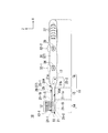
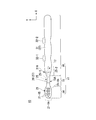
- FIG. 1 is a side view of a toothbrush according to an embodiment of the present invention.
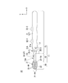
- FIG. 2 is a front view of the toothbrush shown in FIG. In FIG. 2, for convenience of explanation, illustration of the brush portion 12 constituted by the plurality of hair bundles 12-1 shown in FIG. 1 is omitted.
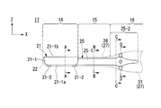
- FIG. 3 is a rear view of the toothbrush shown in FIG. 4 is an enlarged side view of the hard member shown in FIG.
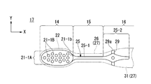
- FIG. 5 is an enlarged front view of the hard member shown in FIG. 6 is an enlarged rear view of the hard member shown in FIG.
- FIGS. 1 to 6 indicate the extending direction of the handle body 11 (the extending direction of the neck portion 15) when the toothbrush 10 is not used.
- 2, 3, 5, and 6 indicate the width direction of the toothbrush 10 (in other words, the second direction orthogonal to the Z direction and the X direction).
- the Z direction shown in FIGS. 1 and 4 indicates a first direction orthogonal to the flocked surface 21-1b when the toothbrush 10 is not used.
- the reference numerals of the constituent elements of the toothbrush 10 other than the constituent elements of the hard member 17 are also shown for convenience of explanation.
- the toothbrush 10 of the present embodiment includes a handle body 11 and a brush portion 12.
- the handle body 11 includes a head part 14, a neck part 15, a handle part 16, a head part 14, a neck part 15, and a hard member 17 constituting a part of the handle part 16.
- the neck portion between the flocked surface 21-1b and the handle portion 16 has a width in the second direction (Y direction) smaller than the width of the head portion 14 (maximum width in the Y direction).
- positioned is demonstrated.
- the head unit 14 includes a base member 21 made of a hard resin and a first soft resin 22 that covers a part of the base member 21.
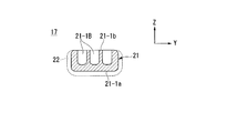
- the base member 21 is a part of the constituent elements of the hard member 17 made of hard resin, and has a base member main body 21-1 and two support portions 21-2.
- the base member body 21-1 reduces the outer shape of the head portion 14 by about 1 to 2 mm so that the first soft resin 22 can be disposed on the side surface and the bottom surface 21-1a of the base member body 21-1. The shape is different.
- the base member main body 21-1 has a tip end portion 21-1A, a bottom surface 21-1a, a flocked surface 21-1b, and a flocked hole 21-1B.
- the tip portion 21-1A is a portion of the base member main body 21-1 located on the side opposite to the side where the head portion 14 and the neck portion 15 are connected.
- the distal end portion 21-1A is a portion facing the user's oral cavity when the user brushes his / her teeth using the toothbrush 10.
- the shape of the tip portion 21-1a may be, for example, a rounded shape (round shape).
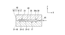
- FIG. 7 is a cross-sectional view of the hard member shown in FIG. 4 in the AA line direction.
- the same components as those shown in FIGS. 1 to 6 are denoted by the same reference numerals.
- reference numerals of the constituent elements of the toothbrush 10 other than the constituent elements of the hard member 17 are also illustrated.
- the bottom surface 21-1a is a portion covered with the first soft resin 22, and is disposed on the opposite side of the flocked surface 21-1b. ing.
- the bottom surface 21-1a can be a flat surface, for example.
- the flocked surface 21-1b is a flat surface.
- the flocked surface 21-1b exposes a plurality of flocked holes 21-1B.
- the flocked surface 21-1b is exposed from the first soft resin 22 as a first exposed portion of the head portion 14.
- the base member main body 21-1 is configured using a hard resin harder than the first soft resin 22, and the plurality of flocked holes 21-1 B and the flocked surfaces 21-1 b are formed from the first soft resin 22.
- the hair bundle 12-1 that constitutes the brush portion 12 can be implanted (planted) into the plurality of planting holes 21-1B by using the flat-line planting method.
- the soft part 26, and the handle part main body 31 are resin-molded using the second mold 51 shown in FIG. -2 (refer to FIG. 12).
- the flocked surface 21-1b comes into contact with the inner surface of one mold 51-2 constituting the second mold 51, the plurality of flocked holes 21-1B and the flocked surface 21-1b are in contact with the first.
- the formation of the soft resin 22 can be suppressed.
- a plurality of flocking holes 21-1B are provided in the base member body 21-1 on the side constituting the flocking surface 21-1b.
- the flocking hole 21-1B is a hole into which the hair bundle 12-1 constituting the brush portion 12 is flocked.
- the arrangement shown in FIG. 2 can be used as the arrangement of the plurality of flock holes 21-1B.
- the arrangement is not limited to this, and any arrangement such as a so-called grid-like arrangement or a staggered arrangement may be used. It may be an array pattern.
- the number of the flocking holes 21-1B is not limited to the number of flocking holes 21-1B shown in FIG. 2, and can be set as appropriate within a range of, for example, 10 to 60 holes. That is, the arrangement of the plurality of flocking holes 21-1B and the number of flocking holes 21-1B can be appropriately set according to the purpose.
- the shape of the flocking hole 21-1B is not particularly limited, and for example, a perfect circle shape, a circular shape such as an ellipse, a polygonal shape such as a triangular shape or a quadrangular shape, or the like can be used. Further, the diameter of the flock hole 21-1B can be determined according to the thickness of the hair bundle 12-1, and can be appropriately set within a range of 1 to 3 mm, for example.
- the thickness of the base member main body 21-1 in the Z direction is 5.0 mm
- the thickness of the base member main body 21-1 in the Z direction is For example, it can be set to 4.2 mm.
- the depth of the plurality of flocking holes 21-1B with respect to the flocking surface 21-1b can be set to, for example, 2.5 mm.
- the thickness of the head portion 14 is a thickness measured at a central portion of the head portion 14 in the X direction.
- the two support portions 21-2 are provided so as to protrude in the Z direction (downward in the case shown in FIG. 1) from the bottom surface 21-1a of the base member main body 21-1.
- One of the two support portions 21-2 is disposed on the front end side of the base member main body 21-1, and the other is disposed on the rear end side of the base member main body 21-1.
- the two support portions 21-2 are arranged to face each other in the X direction.
- the two support portions 21-2 each have a protruding surface 21-2a that is a flat surface.
- the two protruding surfaces 21-2 a are exposed from the outer surface of the first soft resin 22 and are flush with the outer surface of the first soft resin 22. That is, as shown in FIG. 3, the support portion 21-2 is exposed as the second exposed portion of the head portion 14 on the side opposite to the flocked surface 21-1b.
- the protruding surface 21-2a is the first mold 41 (see FIG. 11). It is a part which contacts the inner surface of the. As described above, the protruding surface 21-2a is in contact with the inner surface of the first mold 41 (see FIG. 11), whereby the first soft resin 22 is formed around the two support portions 21-2 and the bottom surface 21-1a. Can be formed.
- the protrusion amount of the two support portions 21-2 (in other words, the distance to the protrusion surface 21-2a with respect to the bottom surface 21-1a) is the first soft resin 22 arranged on the bottom surface 21-1a. Is equal to the thickness in the Z direction. Therefore, the protruding amounts of the two support portions 21-2 can be appropriately set according to the thickness of the first soft resin 22 disposed on the bottom surface 21-1a.
- the protruding amount of the two support portions 21-2 is, for example, 0 .8 mm.
- the thicknesses of the head portion 14 and the base member main body 21-1 are, for example, thicknesses measured at the center portion of the head portion 14 in the X direction.
- the base member 21 configured as described above has a rear end integrally formed with a tip portion of the core portion 25 (one end of the core portion 25).
- a resin harder than the first soft resin 22 is used.
- a resin having a flexural modulus (JIS K7203) in the range of 500 to 3000 MPa can be used.
- Such a hard resin include, for example, polypropylene (PP), polyethylene terephthalate (PET), polybutylene terephthalate (PBT), polycyclohexylene dimethylene terephthalate (PCT), polyacetal (POM), polystyrene (PS). And acrylonitrile / butadiene / styrene resin (ABS), cellulose propionate (CP), polyarylate, polycarbonate, acrylonitrile / styrene copolymer resin (AS), and the like.
- polybutylene terephthalate (PBT) is exemplified. preferable. Since polybutylene terephthalate (PBT) has a high bending strength, the base member 21 can be prevented from being broken or partially broken.
- the said hard resin may be used individually by 1 type, and may be used in combination of 2 or more type as appropriate.
- the first soft resin 22 has a side surface of the base member main body 21-1 and a side surface of the base member main body 21-1 in a state where the flocked surface 21-1b, the plurality of flocked holes 21-1B, and the end surfaces 21-2a of the two support portions 21-2 are exposed. It is provided so as to cover the bottom surface 21-1a. Thus, the first soft resin 22 is disposed so as to cover the tip portion 21-1A of the base member main body 21-1.
- the user can place the toothbrush 10 at the tip portion 21-1A. Since the first soft resin 22 functions as a cushioning material, an external force is applied in the direction from the rear end side to the front end side of the toothbrush 10, and the first soft resin 22 disposed at the front end 21-1A is used. It is possible to prevent the user's oral cavity from being damaged when strongly pressed into the user's oral cavity.
- the thickness of the first soft resin 22 disposed on the side surface and the bottom surface 21-1a of the base member main body 21-1 can be appropriately set within a range of 0.2 to 2.0 mm, for example, depending on the purpose. Although it is possible, it can be 0.8 mm, for example.
- the case where the first soft resin 22 is provided so as to cover the side surface and the bottom surface 21-1a of the base member body 21-1 has been described as an example.
- the soft resin 22 may be disposed so as to cover at least the tip portion 21-1A of the base member main body 21-1.
- a soft resin having a hardness of JIS K 7215 Shore A of 90 or less may be used.
- a soft resin include elastomer resins such as polyolefin elastomers, styrene elastomers, and polyester elastomers. Among them, styrene elastomers are preferable from the viewpoint of weldability with polypropylene (PP). .
- Specific examples of the styrenic elastomer include, for example, Kuraray Co., Ltd. Septon (trade name), Riken Technos Co., Ltd. Rheostomer (trade name), and the like.
- the first soft resin 22 may be appropriately selected according to the type of hard resin constituting the base member 21.
- the first soft resin 22 is preferably, for example, a polyolefin-based elastomer or a styrene-based elastomer, and more preferably a styrene-based elastomer.
- the length (the length in the X direction) of the head unit 14 having the above configuration is not particularly limited, and is preferably in the range of 10 to 30 mm, and more preferably in the range of 12 to 28 mm.
- the length of the head portion 14 is 10 mm or more, it is possible to sufficiently secure the area of the flocked surface 21-1b on which the hair bundle 12-1 can be implanted.
- the operativity of the toothbrush 10 in an intraoral area can be improved as the length of the head part 14 is 30 mm or less.
- the width of the head portion 14 having the above configuration is not particularly limited, and is preferably in the range of 7 to 13 mm, and more preferably in the range of 8 to 12 mm.
- the width of the head portion 14 is 7 mm or more, it is possible to sufficiently secure the area of the flocked surface 21-1b on which the hair bundle 12-1 is implanted.
- the operativity of the toothbrush 10 in oral cavity can be improved as the width
- the position of the boundary between the rear end of the head portion 14 and the tip of the neck portion 15 and the position of the boundary between the rear end of the neck portion 15 and the tip of the handle portion 16 are defined.
- a portion where the width in the Y direction is the same as the maximum width of the head portion 14 or smaller than the maximum width of the head portion 14 between the flocked surface 21-1b and the handle portion 16 is included in the neck portion.
- the width in the Y direction becomes narrower, the amount of change in the width increases, and the change in the width in the Y direction eventually.
- the position where the amount is almost eliminated is defined as the boundary position between the rear end of the head portion 14 and the tip of the neck portion 15. Further, in the X direction from the front end of the neck portion 15 toward the rear end of the handle portion 16, the width in the Y direction becomes wider, the amount of change in the width increases, and eventually the amount of change in the width in the Y direction almost disappears. Is the position of the boundary between the rear end of the neck portion 15 and the front end of the handle portion 16. In the present invention, the position of the rear end side of the handle portion 16 of the flock hole disposed at the position farthest from the front end of the head portion 14 in the X direction from the front end of the head portion 14 is defined as the rear end of the head portion 14.
- the length of the neck portion 15 in the X direction can be appropriately set within a range of, for example, 20 to 60 mm.
- the total length of the head portion and the neck portion is, for example, 40 It can be appropriately set within a range of ⁇ 85 mm.
- the neck portion 15 is a portion that connects the head portion 14 and the handle portion 16.
- the width of the neck portion 15 in the Y direction is configured to be narrower than the width of the head portion 14 and the handle portion 16.
- the thickness of the neck portion 15 in the Z direction can be the same as the thickness of the head portion 14, for example.
- the neck portion 15 includes a core portion 25 that is a component of the hard member 17 and a soft portion 26.
- the core portion 25 extends in the X direction (extending direction of the neck portion 15), and extends through the neck portion 15, and extends in the X direction.
- One end of the core portion 25 is the first portion. 25-1 and a second portion 25-2 disposed in a part of the handle portion 16 and integrated with the 25-1.
- the first portion 25-1 constituting the neck portion 15 will be described, and the second portion 25-2 will be described when the configuration of the handle portion 16 is described.
- FIG. 8 is a cross-sectional view of the hard member (specifically, the first portion) shown in FIG. 4 in the BB line direction.
- the same components as those shown in FIGS. 1 to 6 are denoted by the same reference numerals.
- symbol of the component of the toothbrush 10 other than the component of the hard member 17 is also illustrated for convenience of explanation.
- symbol of the neck part 15 is shown for convenience of explanation.
- the first portion 25-1 has one end integrally formed with the rear end of the base member 21, and the other end is the second portion 25-2. It is configured integrally with.
- the first portion 25-1 is made of a hard resin.
- the first portion 25-1 has a hard resin (bending elastic modulus (JIS K7203)) in the range of 500 to 3000 MPa that is harder than the first soft resin 22 and the second soft resin 27 constituting the soft portion 26. A certain hard resin).
- the first portion 25-1 has the same thickness in the X direction.
- the neck part 15 is bent at the deformed part 15A shown in FIG. 2 (for example, near the center of the neck part 15) (in other words, the tip of the head part 14).
- the thickness and shape of the first portion 25-1 and the thickness of the soft portion 26 disposed around the first portion 25-1 may be determined so as to release the force applied to the first portion 25-1.
- the area of the cut surface of the neck portion 15 obtained by cutting the central portion in the X direction of the neck portion 15 with a plane orthogonal to the X direction (the cut surface 25 of the first portion 25-1).
- -1a area S1 and the area S2 of the cut surface of the soft part 26 is 100%
- the area S1 of the cut surface 25-1a of the first portion 25-1 is 5%.
- the amount may be less than 50%, and preferably 27%, for example.
- the shape of the first portion 25-1 when cut along a plane orthogonal to the X direction for example, a circular shape, an elliptical shape, a square shape, a rectangular shape, a diamond shape, a star shape, or the like can be used.
- the corner of the first portion 25-1 is preferably rounded (round shape).
- the neck portion 15 is in the Z direction (in other words, the direction in which a force is applied when pressing the tip of the brush portion 12 between the teeth or between teeth). It is preferable that the material is not easily deformed (in other words, the tip of the brush portion 12 can be firmly pressed against teeth or between teeth).
- the first width W1 of the first portion 25-1 in the Z direction is in the Y direction (second direction) orthogonal to the Z direction. It may be larger than the second width W2 of the first portion.
- the first width W1 is, for example, 1.5 mm to 3.0 mm
- the second width W2 is, for example, 1.5 mm to 2.0 mm.
- the cleaning performance of the toothbrush 10 is reduced by making the first width W1 of the first portion 25-1 in the Z direction larger than the second width W2 of the first portion in the Y direction.
- the deformable portion 15A can be bent in the Y direction. Thereby, since it becomes possible to escape the force added to the front-end
- the user of the toothbrush 10 when the user of the toothbrush 10 is an infant of 1 to 3 years old, it may run with the toothbrush 10 held in the mouth. In such a case, even if the infant falls, the infant It is possible to prevent the oral cavity from being damaged.
- the first width W1 of the first portion 25-1 in the Z direction is larger than the second width W2 of the first portion in the Y direction.
- the ellipse includes an ellipse in which two semicircles having the same radius are connected by two parallel tangents in addition to a curve formed from a set of points having a constant sum of distances from two focal points. .
- the maximum value of the first width W1 may be configured to be larger than the maximum value of the second width W2.
- the diameter R1 of the neck portion 15 is 3.95 mm
- the first width W1 can be set to 1.975 mm, for example.
- the second width W2 can be set to 1.7 mm, for example.
- the soft part 26 is composed of a second soft resin 27 that houses the first part 25-1 and is softer than the hard resin that constitutes the core part 25.
- the soft portion 26 is a member that prevents the first portion 25-1 from being exposed, and the deformed portion 15A of the neck portion 15 is bent when a strong force is applied to the tip of the head portion 14. It is a member for doing.
- the second soft resin 27 for example, a soft resin having a hardness of 90 or less according to JIS K 6253 Shore A can be used.
- the soft resin exemplified when explaining the first soft resin 22 can be used.
- the second soft resin 27 may be made of a different kind of soft resin from the first soft resin 22 depending on the purpose.
- the hardness of the soft resin used as the first soft resin 22 may be higher than the hardness of the soft resin used for the second soft resin 27.
- tip of the head part 14 and the hardness of the neck part 15 can be varied.
- the same kind of soft resin may be used as the first and second soft resins 22 and 27. Thereby, the number of types of soft resin used when manufacturing the toothbrush 10 can be reduced.
- the outer shape of the cut surface of the soft portion 26 is circular has been described as an example, but the outer shape of the cut surface of the soft portion 26 is not limited thereto.
- the outer shape of the cut surface of the soft portion 26 for example, a part of the long axis is the cut surface 25-
- An elliptical shape coinciding with the major axis of 1a or the above-described oval shape may be used.
- the diameter R1 of the neck portion 15 may be set to a value corresponding to the circumscribed circle of the cut surface 25-1a.
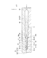
- the handle portion 16 includes a second portion 25-2 (a part of the core portion 25) constituting the core portion 25, and a plurality of projecting portions 29 constituting the hard member 17.
- the handle portion main body 31, the ring-shaped depressions 32-1, 32-2 (ring-shaped depressions), the first rib 34, the second rib 35, and the third rib 37 Have.
- FIG. 9 is a cross-sectional view of the hard member (specifically, the second portion) shown in FIG. 4 in the CC line direction.
- 10 is a cross-sectional view of the hard member (specifically, the second portion) shown in FIG. 4 in the DD line direction.
- 9 and 10 the same components as those shown in FIGS. 1 to 6 are denoted by the same reference numerals.
- steering-wheel part 16 is shown for convenience of explanation.
- 9 and 10 also illustrate reference numerals of the constituent elements of the toothbrush 10 other than the constituent elements of the handle portion 16 for convenience of explanation.
- the second portion 25-2 is made of a hard resin, and one end thereof is integrated with the first portion 25-1.
- the hard resin constituting the second portion 25-2 for example, the same hard resin as that constituting the first portion 25-1 can be used.
- the second portion 25-2 is similar to the X-direction in which the cross-sectional shape perpendicular to the X direction is continuously expanded from one end of the second portion 25-2 toward the plurality of columnar protrusions 29. It is configured as a shape. That is, the second portion 25-2 is configured such that the diameter of the portion provided with the plurality of protrusions 29 is the largest. Further, the portion of the second portion 25-2 that is disposed on the rear end side of the handle portion 16 with respect to the plurality of projecting portions 29 increases from the plurality of projecting portions 29 toward the rear end side of the handle portion 16.
- the cross-sectional shape orthogonal to the X direction is a similar shape whose diameter continuously decreases.
- the shape of the portion of the second portion 25-2 that is disposed on the rear end side of the handle portion 16 with respect to the plurality of protrusion portions 29 is changed from the plurality of protrusion portions 29 to the rear end side of the handle portion 16.
- the same soft resin is used as the first and second soft resins 22 and 27, as shown in FIG.
- the soft resin is introduced into the second mold 51 from the rear end side of the second mold 51 after the hard member 17 is disposed therein, the direction toward the front end of the head portion 14 (X direction) Since the soft resin easily moves (flows), the entire hard member 17 (except the flocked surface 21-1b and the plurality of flocked holes 21-1B) can be accurately wrapped with the soft resin.
- the position and posture of the hard member 17 in the second mold 51 are changed by the introduced soft resin. Can be suppressed.
- the second portion 25-2 is preferably provided at the tip of the handle portion 16, but is not limited thereto.
- the second portion 25-2 may be provided in the neck portion 15.
- protrusions 29 are provided as an example.
- the four protruding portions 29 are arranged in the circumferential direction of the thickest portion of the second portion 25-2.
- An angle formed by two projecting portions 29 arranged at adjacent positions can be set to 90 degrees, for example.
- a space formed between two projecting portions 29 arranged at adjacent positions functions as a path for introducing a soft resin into a second mold 51 shown in FIG. 12 described later.
- the soft resin is supplied to the distal end side of the head portion 21 through the space and is hardened (cured) to become the first soft resin 22.
- Each of the plurality of protruding portions 29 has a protruding surface 29a.
- the projecting surfaces 29a of the plurality of projecting portions 29 are exposed from the outer surface of the handle portion main body 31 (in other words, the outer surface of the handle portion 16) and face the outer surface of the handle portion main body 31 (the outer surface of the handle portion 16). It is comprised so that it may become one.
- the protruding portion 29 as the first protruding portion located on the + Z side is located on the flocked surface 21-1b side through the opening 31a of the handle portion 31 (soft portion 26). Exposed to.
- the protruding portion 29 as the second protruding portion located on the ⁇ Z side is exposed to the side opposite to the flocked surface 21-1b through the opening 31b of the handle portion 31 (soft portion 26).
- the protruding portion 29 located on the + Y side is exposed to the + Y side via the opening 31c of the handle portion 31 (soft portion 26).
- the protruding portion 29 located on the ⁇ Y side is exposed to the ⁇ Y side through the opening 31c of the handle portion 16 (soft portion 26).
- the soft portion 26 in the handle portion 16 has a tapered portion 31A that tapers toward the distal end side, and the openings 31a to 31d are formed in the tapered portion 31A. Yes.
- the protruding portion 29 is exposed to the outside through the openings 31a to 31d formed in the tapered portion 31A of the handle portion 16.
- the cross-sectional shape of the outer surface of the handle portion 16 is substantially circular
- the cross-sectional shape of the protruding surface 29a is an arc shape. Accordingly, each projecting surface 29a is exposed to the outside in the radial direction and exposed to the length direction of the toothbrush 10 and the direction orthogonal to the radial direction.
- the protruding surface 29a of the protruding portion 29 as the first protruding portion located on the + Z side is exposed facing the + Z side and exposed facing the + Y side and the ⁇ Y side.
- the projecting surface 29a of the projecting portion 29 as the second projecting portion located on the ⁇ Z side is exposed facing the ⁇ Z side, and exposed facing the + Y side and the ⁇ Y side. To do.
- the plurality of projecting portions 29 are formed by using the second mold 51 (see FIG. 12) to dispose the hard member 17 in the space 53 of the second mold 51 and molding the handle body 31.
- the protruding surface 29a comes into contact with the inner surface of the second mold 51, thereby having the function of maintaining the posture of the hard member 17 in the space together with the two support portions 21-12 constituting the base member 21 (details are given below) Will be described later).
- the four projecting portions 29 have the projecting surfaces 29 a in contact with the inner surface of the second mold 51, so that the hard member 17 is viewed from four directions. Support the rear end.
- the protrusion amount of the plurality of protrusions 29 is equal to the thickness of the second soft resin 27 disposed around the plurality of protrusions 29. Therefore, the protrusion amounts of the plurality of protrusions 29 are flush with the surface of the second soft resin 27 according to the desired thickness of the second soft resin 27 disposed around the plurality of protrusions 29.
- the value can be set as appropriate. In FIG. 10, when the diameter R2 of the second portion 25-2 is 5.6 mm, the protruding amount T1 of the plurality of protruding portions 29 can be set to 1.77 mm, for example.
- the number of the plurality of protrusions 29 is four. It is not limited to.
- the number of the plurality of protrusions 29 may be, for example, three (in this case, the angle formed by the protrusions 29 arranged at adjacent positions is 120 degrees), or two or more 8 No more than two.
- the shape of the plurality of protrusions 29 may be a shape having a flow path that allows the soft resin to flow from the rear end side of the plurality of protrusions 29 to the front end side of the base member 21.
- the shape of the protrusion 29 shown in FIGS. 6 and 10 is not limited to a cylindrical shape.
- the cross-sectional shape of the plurality of columnar protrusions 29 may be, for example, a star shape or a heart shape excellent in design.
- the handle portion main body 31 is a portion that the user of the toothbrush 10 grips with a hand, and is constituted by the second soft resin 27.
- the handle portion main body 31 by configuring the handle portion main body 31 with the second soft resin 27, a strong external force is applied in the direction from the rear end of the toothbrush 10 toward the tip of the head portion 14 with the toothbrush 10 held in the mouth.
- the handle portion body 31 can be deformed (specifically, bent).
- the handle portion main body 31 is bent, so that it is possible to release an external force from the rear end of the toothbrush 10 toward the front end of the head portion 14 in a different direction. Damage to the oral cavity of 10 users can be suppressed.
- the handle portion body 31 using the second soft resin 27, even when a strong force is applied to the handle portion body 31, the handle portion 16 is broken (in other words, the handle portion 16 Can be suppressed).
- the ring-shaped depressions 32-1 and 32-2 are provided in an annular shape over the entire circumferential direction of the handle portion main body 31.
- the ring-shaped depression 32-1 is disposed on the rear end side of the handle portion 16 with respect to the arrangement position of the second portion 25-2.
- the ring-shaped depression 32-1 is configured by reducing the diameter of the handle portion main body 31. That is, the ring-shaped depression 32-1 has a cross-sectional shape perpendicular to the X direction similar to that of the handle portion main body 31 and a shape in which the diameter continuously decreases.
- the ring-shaped depression 32-2 is disposed, for example, 20 mm to 50 mm away from the position where the ring-shaped depression 32-1 is disposed on the rear end side of the handle portion 16.
- the ring-shaped hollow portion 32-2 is configured by reducing the diameter of the handle portion main body 31. That is, the ring-shaped depression 32-2 has a cross-sectional shape perpendicular to the X direction that is similar to that of the handle main body 31, and has a diameter that continuously decreases.
- the toothbrush 10 is placed in the mouth.
- the ring-shaped depressions 32-1 and 32-2 configured by reducing the diameter of the handle portion main body 31 in the X direction of the handle portion main body 31, the toothbrush 10 is placed in the mouth.
- the ring-shaped depressions 32-1 and 32-2 as the second deformation portions are disposed at the positions where they are disposed.
- the handle portion 16 can be easily bent. As a result, the external force applied in the direction from the rear end of the toothbrush 10 toward the tip of the head portion 14 can be more efficiently released in a direction different from this, so that the oral cavity of the user of the toothbrush 10 is damaged. Can be further suppressed.
- the user can use the toothbrush 10 by disposing the ring-shaped depressions 32-1 and 32-2 formed by reducing the diameter of the handle body 31 in the X direction of the handle body 31.
- the operativity of the toothbrush 10 can be improved.
- the case where two ring-shaped depressions 32-1 and 32-2 are provided in the handle body 31 has been described as an example, but the ring-shaped depressions 32-1 and 32-
- the number of 2 is not limited to two.
- One or more ring-shaped depressions 32-1 and 32-2 may be provided on the handle body 31 as needed.
- the disposition positions of the ring-shaped depressions 32-1 and 32-2 may be disposed on the handle portion main body 31 located behind the disposition position of the second portion 25-2. 3 is not limited to the arrangement position of the ring-shaped depressions 32-1 and 32-2.
- a plurality of the first rib portions 34 are arranged in a portion constituting the side surface (in other words, two side surfaces) of the handle portion main body 31 in the ring-shaped recess portion 32-1.
- a plurality of the second rib portions 35 are arranged in a portion constituting the side surface (in other words, two side surfaces) of the handle portion main body 31 in the ring-shaped recess portion 32-2.
- a plurality of third rib portions 37 are arranged on the side surface (in other words, two side surfaces) of the handle portion main body 31 located on the rear end side with respect to the arrangement position of the second rib portion 35.
- the first to third rib portions 34, 35, and 37 can be composed of the second soft resin 27. In this case, the first to third rib portions 34, 35, and 37 can be collectively formed when the handle portion main body 31 is formed.
- the first to third rib portions 34, 35, and 37 are not necessarily required.
- the brush portion 12 includes a hair bundle 12-1 that is implanted in a plurality of hair implantation holes 21-1 B provided in the base member 21.
- the hair bundle 12-1 is a bundle of a plurality of hairs.
- the length (hair length) of the hair bundle 12-1 with respect to the flocked surface 21-1b can be determined in consideration of the waist and the like required for the hair bundle 12-1. Specifically, the length (hair length) of the hair bundle 12-1 can be appropriately set within a range of 6 to 13 mm, for example.
- the hair bundle 12-1 may be composed of a plurality of hairs having the same length, or may be composed of a plurality of hairs having different hair lengths.
- FIG. 1 as an example of the brush portion 12 constituting the toothbrush 10, a case where the tips of the plurality of hair bundles 12-1 constituting the brush portion 12 are aligned is illustrated as an example, but the present invention is not limited thereto.
- the brush portion 12 may be provided with a step by making the lengths of the plurality of hair bundles 12-1 constituting the brush portion 12 different.
- the thickness (hair bundle diameter) of the hair bundle 12-1 can be determined in consideration of the hair and the like required for the hair bundle 12-1, but can be appropriately set within a range of 1 to 2 mm, for example. it can. All the hair bundles 12-1 may have the same hair bundle diameter or may be different from each other.
- a taper hair that is a hair whose diameter decreases toward the hair tip and the hair tip is sharpened, or a hair tip from the hair transplant surface 21-1b.
- Straight hairs, etc. which are hairs whose diameters are substantially the same facing each other, can be used.
- a hair whose tip is a plane substantially parallel to the flocked surface 21-1b, or one whose tip is rounded into a hemisphere can be used.
- the material of the hair constituting the hair bundle 12-1 is, for example, polyamide such as 6-12 nylon (6-12NY), 6-10 nylon (6-10NY), PET, PBT, polytrimethylene terephthalate (PTT).
- polyamide such as 6-12 nylon (6-12NY), 6-10 nylon (6-10NY), PET, PBT, polytrimethylene terephthalate (PTT).
- resin materials such as polyester such as polyethylene naphthalate (PEN) and polybutylene naphthalate (PBN), and polyolefin such as PP.
- the said resin material used as the material of hair may be used individually by 1 type, or may be used in combination of 2 or more type.
- the hair constituting the hair bundle 12- for example, polyester hair having a multi-core structure having a core portion and at least one or more sheaths provided outside the core portion. May be used.
- the cross-sectional shape of the hair constituting the hair bundle 12-1 is not particularly limited. For example, a round shape such as a true circle or an ellipse, a polygon, a star, a three-leaf clover shape, a four-leaf clover shape, or the like. Can be used.
- the cross-sectional shapes of all the hairs constituting the brush portion 12 may be the same or different.
- the thickness of the hair constituting the hair bundle 12-1 can be determined in consideration of the material of the hair.
- the thickness of the hair can be, for example, 6 to 9 mil. 1 mil is 0.0254 mm.
- the hair bundle 12-1 may be configured by arbitrarily combining a plurality of hairs having different thicknesses in consideration of a feeling of use, a feeling of cleaning, a cleaning effect, durability, and the like.
- the tip portion is made of the first soft resin 22, the head portion 14 having the flocked surface 21-1b, and the handle portion main body 31 made of the second soft resin 27.
- a neck portion 15 that connects the head portion 14 and the handle portion 16, the neck portion 15 extends in the extending direction (X direction) of the neck portion 15, and A core portion 25 made of a hard resin harder than one soft resin 22, and a soft portion 26 made of a second soft resin 27 that houses the core portion 25 and is softer than the hard resin.
- Including the second soft resin 27 as a component when a strong external force is applied in a direction from the rear end of the toothbrush 10 toward the tip of the head portion 14 with the user holding the toothbrush 10 in the mouth.
- Neck 15 and handle Deformation of 16 makes it possible to release the force transmitted to the tip of the head portion 14, and the soft first soft resin 22 disposed at the tip of the head portion 14. Since it becomes possible to make it contact with a user's oral cavity, it can suppress that the user's oral cavity of the toothbrush 10 is damaged.
- the user of the toothbrush 10 when the user of the toothbrush 10 is an infant of 1 to 3 years old, it may run with the toothbrush 10 held in the mouth. In such a case, even if the infant falls, the infant It is possible to prevent the oral cavity from being damaged.
- toothbrush Q the case where the hard member 17 having the base member 21, the core portion 25, and the plurality of protruding portions 29 is used as a constituent element of the toothbrush 10 has been described as an example.
- a toothbrush (hereinafter referred to as “toothbrush Q” for convenience of description) may be configured using a hard member (hereinafter referred to as “hard member P” for convenience of description) in which 21 is excluded from the constituent elements. The same effect as the toothbrush 10 of this Embodiment can be acquired.
- the hard member P may be configured not only to have a plurality of protruding portions 29 only on the rear end side of the core portion 25 but also to have a plurality of protruding portions 29 also on the front end side of the core portion 25.
- a soft resin resin that becomes the first and second soft resins 22 and 27
- a mold not shown
- the toothbrush Q can be manufactured with high accuracy.
- an in-mold method may be used.
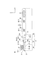
- FIG. 11 is a cross-sectional view showing a manufacturing process of the toothbrush of the present embodiment, and is a diagram for explaining a process of forming a hard member using a first mold.
- FIG. 12 is a cross-sectional view illustrating a manufacturing process of the toothbrush of the present embodiment, and illustrates a process of forming the first soft resin, the soft part, and the handle part main body using the second mold.
- FIG. 11 and 12 the same components as those shown in FIGS. 1 to 10 are denoted by the same reference numerals.
- the arrow shown in FIG. 11 has shown the direction in which hard resin is introduced
- the arrow shown in FIG. 12 has shown the direction in which soft resin (soft resin N mentioned later) is introduced.
- a space 43 corresponding to the shape of the hard member 17 and an introduction for introducing a hard resin into the space 43 are formed by a pair of molds 41-1 and 41-2.
- a first mold 41 having a mouth 45 is prepared.
- the mold 41-2 has a protrusion (not shown) for forming a plurality of flocking holes 21-1B.
- the introduction port 45 is disposed on the rear end side of the space 43.
- the space 43 is filled with a molten hard resin (a resin having a flexural modulus (JIS K7203) in the range of 500 to 3000 MPa) serving as a base material of the hard member 17 through the introduction port 45.
- a molten hard resin a resin having a flexural modulus (JIS K7203) in the range of 500 to 3000 MPa
- JIS K7203 flexural modulus
- the hard member 17 is formed in which the base member 21 including the plurality of flock holes 21-1B and the support portion 21-2, the core portion 25, and the plurality of protrusions 29 are integrated. Thereafter, the hard member 17 is taken out from the first mold 41.
- a second mold 55 having an introduction port 55 for introducing is prepared.
- the joint surfaces of the pair of molds 51-1 and 51-2 are set at an intermediate position in the Z direction of the soft portion 26 (handle portion main body 31) shown in FIGS. 8 to 10, for example.
- the mold 51-2 has a protrusion (not shown) for forming a plurality of flocking holes 21-1B.
- the introduction port 55 is disposed on the rear end side of the space 53.
- the second mold 51 is formed with the ring-shaped depressions 32-1 and 32-2, the first rib 34, the second rib 35, and the third rib 37 shown in FIG. Protrusions are provided for doing so.
- the hard member 17 is disposed at the tip of the space 53 of the second mold 51.
- the inner surface of the mold 51-2 and the flocked surface 21-1b are brought into contact with each other so that the plurality of flocked holes 21-1B are covered, and the end surfaces of the two support portions 21-2 and the mold 51-1.
- the plurality of (in the case of this embodiment, four) projecting surfaces 29a of the projecting portions 29 and the inner surface of the second mold 51 are brought into contact with each other.
- the soft resin N used as the 1st soft resin 22 and the 2nd soft resin 27 (the soft resin which comprises the soft part 26 and the handle
- the position and posture of the hard member 17 in the second mold 51 can be maintained.
- the protruding surface 29a of the protruding portion 29 located on the + Z side contacts the inner surface of the mold 51-2, and the protruding surface 29a of the protruding portion 29 positioned on the ⁇ Z side contacts the inner surface of the mold 51-1.
- the hard member 17 is positioned in the Z direction.
- both the protruding portion 29 positioned on the + Z side and the protruding surface 29a of the protruding portion 29 positioned on the ⁇ Z side face the + Y side and the ⁇ Y side, the mold 51-1 and the mold 51 -2 is also positioned in the Y direction by contacting the inner surface.
- the end surfaces of the two supporting portions 21-2 and the protruding surfaces 29 a of the plurality of protruding portions 29 come into contact with the inner surface of the second mold 51, so that the space between the hard member 17 and the second mold 51 is reduced.
- a gap for forming the first soft resin 22 and the soft portion 26 can be secured.
- the melted soft resin N (resin having a hardness of JIS K 7215 Shore A of 90 or less) is filled into the space 53 through the introduction port 55. Since the inner surfaces of the mold 51-1 and the mold 51-2 at the position corresponding to the tapered portion 31A are shortened so as to taper toward the front end side, the projecting surface 29a is in contact with the inner surface. Thus, the hard member 17 is prevented from moving toward the tip side. Therefore, the hard member 17 is positioned without moving in the X direction even when the resin pressure of the molten soft resin N filled through the introduction port 55 is applied. Thereafter, the first soft resin 22, the soft portion 26, and the handle portion main body 31 are formed by curing the soft resin N.
- Parting lines of minute protrusions are formed on the surface of the soft portion 26 at a position facing the joint surfaces of the mold 51-1 and the mold 51-2 (substantially intermediate position in the Z direction). As a result, the handle body 11 having the head portion 14, the neck portion 15, and the handle portion 16 is formed. Thereafter, the handle body 11 is taken out from the second mold 51.
- the hair bundle 12-1 is implanted into the plurality of flocking holes 21-2 of the head portion 11.
- the toothbrush 10 of this embodiment shown in FIG. 1 is manufactured.
- a flat wire a thin plate made of metal (for example, brass)
- the flat wire flocking method of planting the hair bundle 12-1 with the flat wire sandwiched in the flock hole 21-2 can be used.
- the case of using the flat wire flocking method has been described as an example of the flocking method of the hair bundle 12-1.
- the resin constituting the head unit 14 is used. After the lower end of the hair bundle 12-1 is pressed and fixed into (soft resin or hard resin), or after the lower end of the hair bundle 12-1 is heated to form a molten mass, An in-mold method or the like in which a molten resin is introduced into the substrate may be used.
- the configuration in which the soft portion 26 is provided at the tip portion of the head portion 14 is illustrated, but is not limited thereto, as shown in the side view of FIG. 13 and the front view of FIG.
- a configuration in which the deformable portion 15A in the neck portion 15 is included and the soft portion 26 is provided on the rear end side from the deformable portion 15A may be employed.
- the present invention can be widely applied to a so-called one-tuft toothbrush having a single hair bundle, a toothbrush having a tongue coating auxiliary removing portion, and the like.
- the width in the second direction is smaller than the width of the head portion 14 (maximum width in the Y direction) between the flocked surface 21-1b and the handle portion 16.
- the toothbrush 10 in which the neck portion 15 is disposed has been described, the present invention is not limited to this configuration.
- the width in the Y direction between the flocked surface 21-1b and the handle portion 16 is A toothbrush in the case where the same portion as the maximum width exists is also included in the present invention.
- the deformed portion is disposed as the neck portion, and at least a part of the hard member is accommodated in the rear end side from the deformed portion, and the soft portion formed of the soft resin is disposed. Is done.
- the present invention can be used for a toothbrush capable of suppressing damage to a user's oral cavity.
- Projection surface 31 ... Handle body, 31A ... Taper, 32-1, 32-2 ... Ring-shaped depression (second deformation part), 34 ... First rib, 35 ... 2nd rib part, 37 ... 3rd rib part, 41 ... 1st metal mold
Landscapes
- Brushes (AREA)
- Injection Moulding Of Plastics Or The Like (AREA)
Priority Applications (7)
| Application Number | Priority Date | Filing Date | Title |
|---|---|---|---|
| CN201580046958.7A CN106659289A (zh) | 2014-09-01 | 2015-08-27 | 牙刷 |
| CN202010310721.8A CN111449408B (zh) | 2014-09-01 | 2015-08-27 | 牙刷 |
| CN202010310829.7A CN111480969B (zh) | 2014-09-01 | 2015-08-27 | 牙刷 |
| JP2016546601A JP6591988B2 (ja) | 2014-09-01 | 2015-08-27 | 歯ブラシ |
| CN202010310848.XA CN111358165B (zh) | 2014-09-01 | 2015-08-27 | 牙刷 |
| CN202010310832.9A CN111493506B (zh) | 2014-09-01 | 2015-08-27 | 牙刷 |
| KR1020167036429A KR102577531B1 (ko) | 2014-09-01 | 2015-08-27 | 칫솔 |
Applications Claiming Priority (2)
| Application Number | Priority Date | Filing Date | Title |
|---|---|---|---|
| JP2014-177334 | 2014-09-01 | ||
| JP2014177334 | 2014-09-01 |
Publications (1)
| Publication Number | Publication Date |
|---|---|
| WO2016035678A1 true WO2016035678A1 (ja) | 2016-03-10 |
Family
ID=55439743
Family Applications (1)
| Application Number | Title | Priority Date | Filing Date |
|---|---|---|---|
| PCT/JP2015/074289 Ceased WO2016035678A1 (ja) | 2014-09-01 | 2015-08-27 | 歯ブラシ |
Country Status (4)
| Country | Link |
|---|---|
| JP (5) | JP6591988B2 (enExample) |
| KR (1) | KR102577531B1 (enExample) |
| CN (5) | CN106659289A (enExample) |
| WO (1) | WO2016035678A1 (enExample) |
Cited By (5)
| Publication number | Priority date | Publication date | Assignee | Title |
|---|---|---|---|---|
| JP2018033510A (ja) * | 2016-08-29 | 2018-03-08 | ライオン株式会社 | 歯ブラシの製造方法 |
| JP2018191827A (ja) * | 2017-05-16 | 2018-12-06 | ヤマトエスロン株式会社 | 幼児用歯ブラシ |
| JP2018202004A (ja) * | 2017-06-07 | 2018-12-27 | ヤマトエスロン株式会社 | 幼児用歯ブラシ |
| CN109890248A (zh) * | 2016-10-28 | 2019-06-14 | 狮王株式会社 | 牙刷和牙刷制造方法 |
| JP7619804B2 (ja) | 2020-12-28 | 2025-01-22 | アース製薬株式会社 | 塗布用ブラシ |
Families Citing this family (6)
| Publication number | Priority date | Publication date | Assignee | Title |
|---|---|---|---|---|
| JP2019030583A (ja) * | 2017-08-09 | 2019-02-28 | ライオン株式会社 | 歯ブラシ |
| KR102871094B1 (ko) * | 2019-06-28 | 2025-10-15 | 라이온 가부시키가이샤 | 칫솔 |
| JP7370179B2 (ja) * | 2019-06-28 | 2023-10-27 | ライオン株式会社 | 歯ブラシ |
| WO2021131526A1 (ja) * | 2019-12-23 | 2021-07-01 | ライオン株式会社 | 歯ブラシ |
| CN116685242A (zh) * | 2020-12-24 | 2023-09-01 | 狮王株式会社 | 牙刷以及牙刷的制造方法 |
| CN220554522U (zh) * | 2023-08-29 | 2024-03-05 | 广州星际悦动股份有限公司 | 电动牙刷头及电动牙刷 |
Citations (3)
| Publication number | Priority date | Publication date | Assignee | Title |
|---|---|---|---|---|
| JP3040913U (ja) * | 1997-02-25 | 1997-09-05 | 順元成興業股▲ふん▼有限公司 | 歯ブラシ |
| JPH11155636A (ja) * | 1997-12-01 | 1999-06-15 | Shugo Saito | 歯の清掃具 |
| JPH11512005A (ja) * | 1995-09-08 | 1999-10-19 | コロネット−ヴェルケ ゲゼルシャフト ミット ベシュレンクテル ハフツング | 歯ブラシ |
Family Cites Families (16)
| Publication number | Priority date | Publication date | Assignee | Title |
|---|---|---|---|---|
| JPS5210535Y2 (enExample) * | 1973-02-26 | 1977-03-07 | ||
| JPH0631936Y2 (ja) * | 1989-05-10 | 1994-08-24 | ライオン株式会社 | 歯ブラシ用ハンドル |
| DE69130318T2 (de) * | 1990-06-15 | 1999-05-27 | Victor Alfred Emu Plains Neusuedwales Humphries | Zahnbürste |
| KR970004116Y1 (ko) * | 1994-08-09 | 1997-05-03 | 박종기 | 얼음 파쇄장치 |
| US5630244A (en) * | 1996-01-02 | 1997-05-20 | Chang; Ching-Min | Elastic toothbrush |
| US5735012A (en) * | 1997-04-01 | 1998-04-07 | Chesebrough-Pond's Usa Co., Division Of Conopco, Inc. | Resiliently flexible toothbrush |
| AU5675200A (en) * | 1999-05-24 | 2000-12-12 | Smithkline Beecham Gmbh & Co. Kg | Toothbrush |
| JP2003025376A (ja) * | 2001-07-12 | 2003-01-29 | Lion Corp | 歯ブラシハンドルの製造方法 |
| DE10245086A1 (de) * | 2002-09-27 | 2004-04-08 | Trisa Holding Ag | Verfahren zur Herstellung einer Zahnbürste |
| KR20040077155A (ko) * | 2003-02-28 | 2004-09-04 | 주식회사 엘지생활건강 | 잇몸보호 기능을 가지는 피넛 헤드 형태의 칫솔 |
| JP2005185649A (ja) * | 2003-12-26 | 2005-07-14 | Lion Corp | 歯ブラシハンドル |
| JP2006000466A (ja) * | 2004-06-18 | 2006-01-05 | Lion Corp | 歯ブラシハンドル |
| DE202006011720U1 (de) * | 2006-07-31 | 2007-12-13 | M + C Schiffer Gmbh | Bürste, insbesondere Zahnbürste |
| DE102009011836A1 (de) * | 2009-03-05 | 2010-09-09 | M + C Schiffer Gmbh | Bürste, insbesondere Zahnbürste |
| JP5830277B2 (ja) * | 2011-06-20 | 2015-12-09 | ライオン株式会社 | 歯ブラシ |
| JP5806922B2 (ja) * | 2011-12-07 | 2015-11-10 | ライオン株式会社 | 歯ブラシ |
-
2015
- 2015-08-27 JP JP2016546601A patent/JP6591988B2/ja active Active
- 2015-08-27 CN CN201580046958.7A patent/CN106659289A/zh active Pending
- 2015-08-27 CN CN202010310832.9A patent/CN111493506B/zh active Active
- 2015-08-27 CN CN202010310721.8A patent/CN111449408B/zh active Active
- 2015-08-27 WO PCT/JP2015/074289 patent/WO2016035678A1/ja not_active Ceased
- 2015-08-27 CN CN202010310848.XA patent/CN111358165B/zh active Active
- 2015-08-27 KR KR1020167036429A patent/KR102577531B1/ko active Active
- 2015-08-27 CN CN202010310829.7A patent/CN111480969B/zh active Active
-
2019
- 2019-09-18 JP JP2019169597A patent/JP2020072789A/ja active Pending
- 2019-09-18 JP JP2019169598A patent/JP6903108B2/ja active Active
- 2019-09-18 JP JP2019169599A patent/JP6893541B2/ja active Active
-
2021
- 2021-03-22 JP JP2021047391A patent/JP7069377B2/ja active Active
Patent Citations (3)
| Publication number | Priority date | Publication date | Assignee | Title |
|---|---|---|---|---|
| JPH11512005A (ja) * | 1995-09-08 | 1999-10-19 | コロネット−ヴェルケ ゲゼルシャフト ミット ベシュレンクテル ハフツング | 歯ブラシ |
| JP3040913U (ja) * | 1997-02-25 | 1997-09-05 | 順元成興業股▲ふん▼有限公司 | 歯ブラシ |
| JPH11155636A (ja) * | 1997-12-01 | 1999-06-15 | Shugo Saito | 歯の清掃具 |
Cited By (16)
| Publication number | Priority date | Publication date | Assignee | Title |
|---|---|---|---|---|
| CN109862806A (zh) * | 2016-08-29 | 2019-06-07 | 狮王株式会社 | 牙刷的制造方法 |
| WO2018043249A1 (ja) * | 2016-08-29 | 2018-03-08 | ライオン株式会社 | 歯ブラシの製造方法 |
| KR102425591B1 (ko) | 2016-08-29 | 2022-07-28 | 라이온 가부시키가이샤 | 칫솔의 제조 방법 |
| JP2018033510A (ja) * | 2016-08-29 | 2018-03-08 | ライオン株式会社 | 歯ブラシの製造方法 |
| KR20190039685A (ko) * | 2016-08-29 | 2019-04-15 | 라이온 가부시키가이샤 | 칫솔의 제조 방법 |
| US20190274417A1 (en) * | 2016-10-28 | 2019-09-12 | Lion Corporation | Toothbrush and method for manufacturing toothbrush |
| CN109890248A (zh) * | 2016-10-28 | 2019-06-14 | 狮王株式会社 | 牙刷和牙刷制造方法 |
| KR20190069383A (ko) * | 2016-10-28 | 2019-06-19 | 라이온 가부시키가이샤 | 칫솔 및 칫솔 제조 방법 |
| EP3533357A4 (en) * | 2016-10-28 | 2020-05-20 | Lion Corporation | TOOTHBRUSH AND METHOD FOR PRODUCING A TOOTHBRUSH |
| US11013310B2 (en) * | 2016-10-28 | 2021-05-25 | Lion Corporation | Toothbrush and method for manufacturing toothbrush |
| CN109890248B (zh) * | 2016-10-28 | 2022-03-08 | 狮王株式会社 | 牙刷和牙刷制造方法 |
| KR102627142B1 (ko) * | 2016-10-28 | 2024-01-19 | 라이온 가부시키가이샤 | 칫솔 및 칫솔 제조 방법 |
| JP7072200B2 (ja) | 2017-05-16 | 2022-05-20 | ヤマトエスロン株式会社 | 幼児用歯ブラシ |
| JP2018191827A (ja) * | 2017-05-16 | 2018-12-06 | ヤマトエスロン株式会社 | 幼児用歯ブラシ |
| JP2018202004A (ja) * | 2017-06-07 | 2018-12-27 | ヤマトエスロン株式会社 | 幼児用歯ブラシ |
| JP7619804B2 (ja) | 2020-12-28 | 2025-01-22 | アース製薬株式会社 | 塗布用ブラシ |
Also Published As
| Publication number | Publication date |
|---|---|
| CN111493506A (zh) | 2020-08-07 |
| KR20170051379A (ko) | 2017-05-11 |
| CN111480969B (zh) | 2022-05-17 |
| JP6893541B2 (ja) | 2021-06-23 |
| JP2021090889A (ja) | 2021-06-17 |
| KR102577531B1 (ko) | 2023-09-12 |
| JPWO2016035678A1 (ja) | 2017-06-15 |
| CN111449408A (zh) | 2020-07-28 |
| JP7069377B2 (ja) | 2022-05-17 |
| JP2020072789A (ja) | 2020-05-14 |
| CN111358165A (zh) | 2020-07-03 |
| JP6903108B2 (ja) | 2021-07-14 |
| CN111449408B (zh) | 2023-09-08 |
| JP6591988B2 (ja) | 2019-10-16 |
| CN111358165B (zh) | 2023-09-08 |
| JP2020018871A (ja) | 2020-02-06 |
| CN106659289A (zh) | 2017-05-10 |
| CN111493506B (zh) | 2023-08-22 |
| CN111480969A (zh) | 2020-08-04 |
| JP2020018870A (ja) | 2020-02-06 |
Similar Documents
| Publication | Publication Date | Title |
|---|---|---|
| JP7069377B2 (ja) | 歯ブラシ | |
| JP7166372B2 (ja) | 歯ブラシ | |
| CN109890248B (zh) | 牙刷和牙刷制造方法 | |
| JP6721342B2 (ja) | 歯間ブラシ | |
| WO2016208333A1 (ja) | 歯ブラシ | |
| JP6675212B2 (ja) | 歯間清掃具の製造方法 | |
| JP2021102085A (ja) | 歯ブラシ | |
| JPWO2015137487A1 (ja) | 歯ブラシ用ハンドル体、歯ブラシ、及び歯ブラシ用ハンドル体の製造方法 | |
| JP5785819B2 (ja) | 歯ブラシ | |
| JP6869634B2 (ja) | 歯ブラシ | |
| JP6842904B2 (ja) | 歯ブラシ | |
| JP6842905B2 (ja) | 歯ブラシと歯ブラシの製造方法 |
Legal Events
| Date | Code | Title | Description |
|---|---|---|---|
| 121 | Ep: the epo has been informed by wipo that ep was designated in this application |
Ref document number: 15838019 Country of ref document: EP Kind code of ref document: A1 |
|
| ENP | Entry into the national phase |
Ref document number: 20167036429 Country of ref document: KR Kind code of ref document: A |
|
| ENP | Entry into the national phase |
Ref document number: 2016546601 Country of ref document: JP Kind code of ref document: A |
|
| NENP | Non-entry into the national phase |
Ref country code: DE |
|
| 122 | Ep: pct application non-entry in european phase |
Ref document number: 15838019 Country of ref document: EP Kind code of ref document: A1 |