WO2016031323A1 - ラックバー及びラックバーの製造方法 - Google Patents
ラックバー及びラックバーの製造方法 Download PDFInfo
- Publication number
- WO2016031323A1 WO2016031323A1 PCT/JP2015/064876 JP2015064876W WO2016031323A1 WO 2016031323 A1 WO2016031323 A1 WO 2016031323A1 JP 2015064876 W JP2015064876 W JP 2015064876W WO 2016031323 A1 WO2016031323 A1 WO 2016031323A1
- Authority
- WO
- WIPO (PCT)
- Prior art keywords
- rack
- tooth
- pair
- rack bar
- axis
- Prior art date
- Legal status (The legal status is an assumption and is not a legal conclusion. Google has not performed a legal analysis and makes no representation as to the accuracy of the status listed.)
- Ceased
Links
Images


Classifications
-
- B—PERFORMING OPERATIONS; TRANSPORTING
- B62—LAND VEHICLES FOR TRAVELLING OTHERWISE THAN ON RAILS
- B62D—MOTOR VEHICLES; TRAILERS
- B62D3/00—Steering gears
- B62D3/02—Steering gears mechanical
- B62D3/12—Steering gears mechanical of rack-and-pinion type
- B62D3/126—Steering gears mechanical of rack-and-pinion type characterised by the rack
-
- B—PERFORMING OPERATIONS; TRANSPORTING
- B21—MECHANICAL METAL-WORKING WITHOUT ESSENTIALLY REMOVING MATERIAL; PUNCHING METAL
- B21K—MAKING FORGED OR PRESSED METAL PRODUCTS, e.g. HORSE-SHOES, RIVETS, BOLTS OR WHEELS
- B21K1/00—Making machine elements
- B21K1/76—Making machine elements elements not mentioned in one of the preceding groups
- B21K1/767—Toothed racks
-
- B—PERFORMING OPERATIONS; TRANSPORTING
- B62—LAND VEHICLES FOR TRAVELLING OTHERWISE THAN ON RAILS
- B62D—MOTOR VEHICLES; TRAILERS
- B62D3/00—Steering gears
- B62D3/02—Steering gears mechanical
- B62D3/12—Steering gears mechanical of rack-and-pinion type
-
- F—MECHANICAL ENGINEERING; LIGHTING; HEATING; WEAPONS; BLASTING
- F16—ENGINEERING ELEMENTS AND UNITS; GENERAL MEASURES FOR PRODUCING AND MAINTAINING EFFECTIVE FUNCTIONING OF MACHINES OR INSTALLATIONS; THERMAL INSULATION IN GENERAL
- F16H—GEARING
- F16H19/00—Gearings comprising essentially only toothed gears or friction members and not capable of conveying indefinitely-continuing rotary motion
- F16H19/02—Gearings comprising essentially only toothed gears or friction members and not capable of conveying indefinitely-continuing rotary motion for interconverting rotary or oscillating motion and reciprocating motion
- F16H19/04—Gearings comprising essentially only toothed gears or friction members and not capable of conveying indefinitely-continuing rotary motion for interconverting rotary or oscillating motion and reciprocating motion comprising a rack
-
- F—MECHANICAL ENGINEERING; LIGHTING; HEATING; WEAPONS; BLASTING
- F16—ENGINEERING ELEMENTS AND UNITS; GENERAL MEASURES FOR PRODUCING AND MAINTAINING EFFECTIVE FUNCTIONING OF MACHINES OR INSTALLATIONS; THERMAL INSULATION IN GENERAL
- F16H—GEARING
- F16H55/00—Elements with teeth or friction surfaces for conveying motion; Worms, pulleys or sheaves for gearing mechanisms
- F16H55/02—Toothed members; Worms
- F16H55/26—Racks
Definitions
- the present invention relates to a rack bar that is applied to, for example, a rack and pinion type steering device of a vehicle and is used to transmit a steering force to a steered wheel, and a method of manufacturing the rack bar.
- Patent Document 1 As a rack bar applied to a conventional rack and pinion type steering device, for example, one described in Patent Document 1 below is known.
- this rack bar is formed by sandwiching a solid round bar-shaped material between an upper mold and a lower mold, causing the material of the material to plastically flow, and letting the surplus material escape to the side as a pair of burrs.
- the rack teeth are formed in a circumferential range of a transverse cross section (circular cross section) in a predetermined axial direction range by so-called die forging.
- the rack teeth are formed so as to be within the range of the circular cross section of the rack bar (the circular cross section of the round bar). There was a problem that could not be secured.
- the present invention has been devised in view of such technical problems, and manufacturing a rack bar and a rack bar capable of expanding the tooth width dimension of the rack teeth from the circular cross section of the material while being formed by die forging. A method is provided.
- the present invention is a rack bar formed by die forging a metal rod-shaped material having a substantially circular cross section, and is provided at both ends in the tooth width direction of rack teeth.
- a pair of tooth width enlarged portions projecting outward from the outer shape of the substantially circular cross section of the raw material due to plastic flow of the raw material, and a first portion used for forming the rack tooth side during the die forging.
- a pair of burrs protruding as a result of the flow of the material into a gap formed between the first mold and the second mold to be used for die forging in cooperation with the first mold is removed.
- a pair of burr removing portions provided so that the center position of each burr is biased toward the rack tooth side with respect to the axis.
- the rack bar is die-forged by transferring the rack tooth forming portion and the tooth width enlarged forming portion by pressurizing and deforming the material between the first forming die and the second forming die. And a burr removing step of removing a part of the burr formed by the material flowing into the pair of burr forming portions in the forging step to form a pair of burr removing portions. It is manufactured with.
- the tooth width dimension of the rack tooth can be secured larger than the circular cross section of the material by the pair of tooth width enlarged portions, and the meshing rate with the pinion teeth can be improved.
- the fluidity of the material in the pair of tooth width enlarged portions is improved, and the loss of the material in the tooth width enlarged portions can be suppressed. it can.
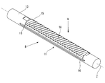
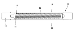
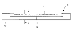
- FIG. 1 is a schematic view of a steering apparatus to which a rack bar according to the present invention is applied. It is a perspective view of the rack bar shown in FIG. It is the arrow line view seen from the A direction of the rack bar shown in FIG. It is the arrow line view seen from the B direction of the rack bar shown in FIG.
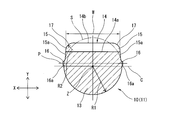
- FIG. 5 is a cross-sectional view taken along the line CC in FIG. 4.
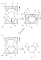
- the manufacturing method (manufacturing process) of the rack bar which concerns on this invention is shown, (a) is the state which set the raw material to the metal mold
- FIG. 6 is a view corresponding to FIG. 5 illustrating a second embodiment of the rack bar according to the present invention.
- the rack bar is applied to an automobile steering device as in the conventional case.
- FIG. 1 to 6 show a first embodiment of a rack bar or the like according to the present invention.
- a steering device to which the rack bar is applied will be described.
- One end side in the direction is connected to the steering wheel SW so as to be integrally rotatable, and one end side in the axial direction is connected to the other end side of the input shaft 1 via a torsion bar (not shown) so as to be relatively rotatable.
- An output shaft 2 whose end side is linked to the steered wheels WL and WR via the rack and pinion mechanism RP, a torque sensor TS for detecting the steering torque based on the relative rotational displacement of the input shaft 1 and the output shaft 2,
- a motor unit MU that applies a steering assist torque according to the steering torque of the driver to the rack bar 10 to be described later based on the detection result of the vehicle speed sensor, etc., and the output (rotational force) of the motor unit MU is decelerated.
- One transmission mechanism RG for transmitting converted into the axial movement force of the rack shaft 10 to be described later, and is mainly comprised.
- the rack and pinion mechanism RP includes rack teeth 14 formed in a predetermined axial range of a rod-shaped rack bar 10 that is arranged in a form substantially orthogonal to the pinion teeth 2 a formed on the outer periphery of one end of the output shaft 2.
- rack teeth 14 are configured so that the rack bar 10 moves in the axial direction in accordance with the rotation direction of the output shaft 2.
- Both ends of the rack bar 10 are linked to the steered wheels WR and WL via a tie rod 3 and a knuckle arm (not shown), respectively, and the above-described illustration is provided via the tie rod 3 as the rack bar 10 moves in the axial direction.
- the outer knuckle arm By pulling the outer knuckle arm, the directions of the steered wheels WR and WL are changed.
- the rack bar 10 has rack teeth 14 formed on the outer periphery, a first member 11 constituting the rack and pinion mechanism RP, and a ball screw groove (not shown) formed on the outer periphery.
- a first housing 4a on one end side that accommodates the rack and pinion mechanism RP and a second housing 4b on the other end side that accommodates the transmission mechanism RG are not shown. It is arrange
- the first member 11 includes a rack main body 13 formed of a rod-shaped metal material having a substantially circular cross section, and a substantially circular cross section of the rack main body 13 (hereinafter referred to as “the first main member 11”).
- the rack teeth 14 formed by die forging, which will be described later, around the axis Z passing through the center of “circular cross section”), and both ends of the rack teeth 14 in the tooth width direction (X direction in FIG. 5)
- a pair of tooth width expanding portions 15 that extend to the rack teeth 14 to increase the tooth width of the rack teeth 14 and a part of a burr 18 (see FIG. 6C), which will be described later, formed along with the die forging.
- a pair of deburring portions 16 formed by removal.
- the first member 11 has a configuration in which the rack teeth 14 are formed substantially symmetrically by forming the rack teeth 14 in a substantially intermediate region in the extending direction.
- Each tooth width expanding portion 15 is formed by plastic flow of the material of the material along with the formation of the rack teeth 14 by pressure deformation at the time of die forging described later, particularly as shown in FIG. It is provided so as to protrude outward from the outer shape S of the circular cross section (see the phantom line in FIG. 5), that is, to protrude outward in the radial direction of the axis Z with respect to the outer shape S of the circular cross section.
- Each tooth width expanding portion 15 is formed such that the dimension (tooth width dimension) W of the rack tooth 14 in the tooth width direction gradually decreases from the tooth bottom side to the tooth tip side of the rack tooth 14. Both ends in the tooth width direction (X direction) are configured as tapered portions 15a. Furthermore, both end sides in the tooth width direction of each tooth width expanding portion 15 are outside the tooth bottom surface 14a in the radial direction of the axis Z of the rack body 13 and outside the outer shape S of the circular cross section. A radius of curvature R2 smaller than the radius of curvature R1 of the rack body 13 (material) is formed at a corner portion constituted by the tapered portions 15a and the tooth tip surfaces 14b which are the outermost radial direction of the axis Z. A pair of arcuate portions 17 having a rounded chamfer shape are provided.
- Each of the burr removing portions 16 has the material of the material in each burr forming portion 23 of the first forming die D1 and the second forming die D2 used for the die forging as the rack teeth 14 are formed in die forging described later. It is formed by removing the tip side of a pair of burrs 18 that are formed to project by flowing in. Each burr removing portion 16 is provided in such a manner that the center position P of each burr 18 is biased to the rack tooth 14 side with respect to the axis Z of the rack body 13 (center line C passing through the axis Z). ing. More specifically, the portion farthest from the rack teeth 14 in the direction (Y direction) orthogonal to the tooth width direction (X direction), that is, the lower end 16a in FIG. 5 is the axis Z (the center line C). Is configured to match.
- the motor unit MU is supported and fixed to the second housing 4b at one end in the axial direction from which the output shaft 31a protrudes.
- the motor unit MU is racked via a transmission mechanism RG by rotationally driving an input pulley 41 described later.
- An electric motor 31 that applies steering assist torque to the bar 10 and an electronic controller 32 that is attached to the other end of the electric motor 31 and that controls driving of the electric motor 31 according to predetermined parameters such as the steering torque and vehicle speed. are integrally configured.
- the transmission mechanism RG is provided on the outer periphery of the output shaft 31a of the electric motor 31 so as to be integrally rotatable.
- the transmission pulley RG is rotatable relative to the outer periphery of the rack bar 10 and the input pulley 41 that rotates about the axis L1 of the output shaft 31a.
- An output pulley 42 that rotates about the axis L2 of the rack bar 10 based on the rotational force of the input pulley 41, and is interposed between the output pulley 42 and the rack bar 10 to decelerate the rotation of the output pulley 42
- the rotation of the input pulley 41 is transmitted to the output pulley 42 by being wound around the ball screw mechanism (not shown) that converts the rack bar 10 into the axial motion and the input pulley 41 and the output pulley 42.
- the belt 43 is used mainly for synchronous rotation of the pulleys 41 and 42.
- the molding die used in the manufacturing method will be described.
- the molding die is an axis of the rack body 13 (material).
- a first molding die D1 which is a movable mold that is arranged on one side around Z and serves to form the rack teeth 14, and is opposed to the opposite side of the first molding die D1, and cooperates with the first molding die D1.
- the first mold D1 is formed with irregularities on the inner bottom portion, and is provided on both sides of the rack tooth forming portion 21 and the rack tooth forming portions 21 used for forming the rack teeth 14, and with the formation of the rack teeth 14
- a pair of burr forming portions 22 formed on the contact surface between the pair of tooth width expanding portions 22 forming the respective tooth width expanding portions 15 and the second molding die D2 and forming the respective burrs 18.
- a material support portion 24 having a substantially semicircular cross section corresponding to the outer shape of the material M1 is recessed in the second molding die D2, and the material support portion 24 is used to support the material during die forging described later. Is possible.
- the mold was opened by raising the first molding die D1.
- the material M1 is set on the material support portion 24 of the second mold D2.
- the first molding die D1 is lowered, and the material M1 is pressed and deformed in such a manner that the material M1 is sandwiched between the molding dies D1 and D2. 21 and the tooth width expansion forming portion 22 are transferred to perform die forging (forging process of the present invention).
- the rack tooth forming portion 21 and the tooth width expanding forming portion 22 are plastically flowed into the burr forming portion 23 (the gap V between the first and second molding dies D1 and D2 formed by the burr forming portion 23).
- the rack teeth 14 including a pair of tooth width enlarged portions 15 are formed by being transferred, and a pair of burrs 18 are formed by the burr forming portion 23 (gap V).
- the first mold D1 is raised to open the die, and the forged product M2 that has been forged is taken out.
- the pair of burrs 18 formed by the forging process are cut off to form a pair of burrs removing portions 16 (of the present invention). Deburring step) and the production of the rack bar 10 is completed.
- the tooth width dimension W of the rack teeth 14 is changed to the circular cross section of the rack body 13 (material).
- the meshing ratio with the pinion teeth 3a is improved.
- the pair of tooth width enlarged portions 15 is formed by die forging, it can be formed more easily and at a lower cost than the case of forming the pair of tooth width enlarged portions 15 by closed forging. The reduction in productivity and cost of the rack bar 10 due to the provision of the tooth width enlarged portion 15 can be minimized.
- the pair of burr removing portions 16 are offset on the tooth tip side of the rack teeth 14 (see FIG. 5), so that each tooth width during the forging process is set.
- each tooth width during the forging process is set.
- each burr removing portion 16 is sufficiently offset to the rack tooth 14 side, There is a merit that the loss of material in the tooth width enlarged portion 15 can be more effectively suppressed.
- each tooth width enlarged portion 15 is formed such that the tooth width dimension W of the rack tooth 14 including each tooth width enlarged portion 15 gradually decreases from the root side to the tooth tip side of the rack tooth 14. Then, by gradually reducing the tooth width dimension W on the tooth tip side that is far from the axis Z of the rack body 13, the filling property into each tooth width expansion forming portion 22 during the forging process is further improved. Thus, the material loss in each tooth width enlarged portion 15 can be effectively suppressed.
- the tooth width expanding forming portion 22 is most distant from the axis Z of the rack body 13.
- the filling property of the material into the part that can be far is improved, and it is possible to more effectively suppress the loss of the material in each tooth width enlarged portion 15.
- the pair of arc-shaped portions 17 are also formed outside the tooth bottom surface 14a of the rack tooth 14 in the radial direction of the axis Z of the rack body 13 (see FIG. 5), so that each tooth width is increased.
- the material loss in each of the tooth width enlarged portions 15 is further effectively suppressed.
- the pair of arcuate portions 17 are formed outside the outer shape S of the rack body 13 (material) in the radial direction of the axis Z of the rack body 13 (see FIG. 5). This also serves to ensure both the securing of the tooth width dimension W of the rack teeth 14 larger than the circular cross section of the rack body 13 and the formation of the pair of arcuate portions 17.
- the rack teeth 14 are formed in substantially the intermediate region in the extending direction of the first member 11 of the rack bar 10, the shape of the rack bar 10 can be made substantially symmetrical in the extending direction. As a result, the balance of the die forging becomes good, and the molding accuracy of the rack bar 10 can be improved.
- FIG. 7 shows a second embodiment of the rack bar and the manufacturing method of the rack bar according to the present invention.
- the opposite side of the rack body 14 around the axis Z of the rack body 14. In other words, at the lower end position on the opposite side of the rack tooth 14 with respect to the axis Z of the rack body 13, the inner side of the circular cross section (outer shape S) of the rack body 13 (material) in the radial direction of the axis Z.
- a recessed portion 19 that is recessed is formed.
- the recess 19 may be processed at the same time in the forging process in the first embodiment, or may be separately forged after the forging process.
- the concave portion 19 can be formed by providing the second molding die D2 as a fixed die by providing the concave portion forming portion 25 for forming the concave portion 19, and further, as a movable die. It can also be formed by providing the recess forming part 25 in the first mold D1.
- the recesses 19 are provided, so that the plastic flow of the material accompanying the formation (forging) of the recesses 19 causes the respective tooth width enlarged portions. 15 improves the fluidity of the material related to the formation of 15, that is, the filling property of the material into each of the tooth width enlarged portions 22, and more effectively suppress the material loss in each tooth width enlarged portion 15. it can.
- the present invention is not limited to the configuration of each of the above-described embodiments.
- the rack bar 10 is applied to a belt-driven electric power steering device as an example.
- the embodiment is not limited to this type of steering device.
- the present invention can be applied to various steering devices such as an electric power steering device.
- the shape of the rack bar can be made substantially symmetrical in the extending direction, so that the balance of die forging is improved and the forming accuracy of the rack bar is improved.
- a rack bar wherein a recess is provided on the opposite side of the rack tooth around the axis so as to be recessed inwardly from a substantially circular cross section of the material in the radial direction of the axis.
- the concave portion improves the filling property of the material into the tooth width enlarged portion by the amount of the material before forming the concave portion, and more effectively suppresses the material loss in the tooth width enlarged portion. it can.
- the pair of arc-shaped portions can improve the filling property of the material into the portion that can be farthest from the axis, and can more effectively suppress the material loss in the tooth width expansion portion.
- the rack bar is formed in a region substantially in the middle in the extending direction of the material.
- the shape of the rack bar can be made substantially symmetrical in the extending direction, so that the balance of die forging is improved and the forming accuracy of the rack bar is improved.
- a method for manufacturing a rack bar comprising: a concave portion recessed inward of the outer shape of the material in a radial direction of the axis line on the opposite side of the rack tooth from the periphery of the axis line.
- the concave portion improves the filling property of the material into the tooth width enlarged portion by the amount of the material before forming the concave portion, and further serves to further suppress the loss of material in the tooth width enlarged portion.
Landscapes
- Engineering & Computer Science (AREA)
- Mechanical Engineering (AREA)
- General Engineering & Computer Science (AREA)
- Chemical & Material Sciences (AREA)
- Combustion & Propulsion (AREA)
- Transportation (AREA)
- Forging (AREA)
- Gears, Cams (AREA)
- Transmission Devices (AREA)
Abstract
Description
前記1対の円弧状部は、前記軸線の径方向において、前記ラック歯の歯底面よりも外側に形成されることを特徴とするラックバー。
前記1対の円弧状部は、前記軸線の径方向において、前記素材の外形よりも外側に形成されることを特徴とするラックバー。
前記ラック歯は、前記素材の延出方向のほぼ中間部の領域に形成されていることを特徴とするラックバー。
前記ラック歯に対して前記軸線周りの反対側に、前記軸線の径方向において前記素材のほぼ円形断面よりも内側に凹む凹部が設けられていることを特徴とするラックバー。
前記1対の歯幅拡大部における前記歯幅方向の両端側に、それぞれ前記素材よりも小さい曲率半径を有する1対の円弧状部が設けられていることを特徴とするラックバーの製造方法。
前記1対の円弧状部は、前記軸線の径方向において、前記ラック歯の歯底面よりも外側に形成されることを特徴とするラックバー。
前記1対の円弧状部は、前記軸線の径方向において、前記素材の外形よりも外側に形成されることを特徴とするラックバー。
前記1対のバリ除去部は、それぞれ前記歯幅方向と直交する方向において、前記ラック歯から最も離間した部分が、前記軸線と一致又は該軸線よりも前記ラック歯側に偏倚していることを特徴とするラックバーの製造方法。
前記ラック歯は、前記素材の延出方向のほぼ中間部の領域に形成されていることを特徴とするラックバーの製造方法。
前記ラック歯に対して前記軸線周りの反対側に、前記軸線の径方向において前記素材の外形よりも内側に凹む凹部が設けられていることを特徴とするラックバーの製造方法。
13…ラック本体
14…ラック歯
15…歯幅拡大部
16…バリ除去部
Z…軸線
S…外形
Claims (16)
- 横断面がほぼ円形の素材を型鍛造で加工することによって形成され、ステアリングホイールに連係して回転するピニオン軸の回転運動を軸方向運動に変換することによって操舵操作を転舵輪に伝達するラックバーであって、
金属材料によって棒状に形成されたラック本体と、
前記ラック本体のうち前記素材のほぼ円形の横断面の中心を通る軸線周りに設けられ、前記ピニオン軸に形成されるピニオン歯と噛合するラック歯と、
前記ラック歯の歯幅方向の両端側に設けられ、前記型鍛造の際に前記素材の材料が塑性流動することによって前記素材のほぼ円形の断面の外形よりも外側に突出してなる1対の歯幅拡大部と、
前記型鍛造の際に前記ラック歯側の形成に供する第1成形型と該第1成形型と協働して前記型鍛造に供する第2成形型との間に形成される隙間に前記素材が流入することで突設される1対のバリを除去することにより形成され、該各バリの中心位置が前記軸線よりも前記ラック歯側に偏倚して設けられた1対のバリ除去部と、
を備えたことを特徴とするラックバー。 - 前記1対の歯幅拡大部は、該両歯幅拡大部を含む前記ラック歯の歯幅寸法が前記ラック歯の歯底側から歯先側に向けて漸次減少するように形成されることを特徴とする請求項1に記載のラックバー。
- 前記1対の歯幅拡大部における前記歯幅方向の両端側に、それぞれ前記素材よりも小さい曲率半径を有する1対の円弧状部が設けられていることを特徴とする請求項2に記載のラックバー。
- 前記1対の円弧状部は、前記軸線の径方向において、前記ラック歯の歯底面よりも外側に形成されることを特徴とする請求項3に記載のラックバー。
- 前記1対の円弧状部は、前記軸線の径方向において、前記素材の外形よりも外側に形成されることを特徴とする請求項3に記載のラックバー。
- 前記1対のバリ除去部は、それぞれ前記歯幅方向と直交する方向において、前記ラック歯から最も離間した部分が、前記軸線と一致又は該軸線よりも前記ラック歯側に偏倚していることを特徴とする請求項1に記載のラックバー。
- 前記ラック歯は、前記素材の延出方向のほぼ中間部の領域に形成されていることを特徴とする請求項1に記載のラックバー。
- 前記ラック歯に対して前記軸線周りの反対側に、前記軸線の径方向において前記素材のほぼ円形断面よりも内側に凹む凹部が設けられていることを特徴とする請求項1に記載のラックバー。
- 横断面がほぼ円形をなす金属製の棒状の素材を型鍛造で加工することにより形成され、ステアリングホイールに連係して回転するピニオン軸の回転運動を、該ピニオン軸のピニオン歯に噛合するラック歯をもって軸方向運動に変換することによって、操舵操作を転舵輪に伝達するラックバーの製造方法であって、
前記素材は、該素材のほぼ円形の横断面の中心を通る軸線周りの一方側に配置され、前記ラック歯の形成に供する第1成形型と、該第1成形型の反対側に配置され、該第1成形型と協働して前記型鍛造に供する第2成形型と、によって加工され、
前記第1成形型は、前記ラック歯の形成に供するラック歯形成部と、前記型鍛造の際に前記素材の材料が塑性流動することによって前記素材のほぼ円形の断面の外形よりも外側に突出する1対の歯幅拡大部を前記ラック歯の歯幅方向の両端側に形成する歯幅拡大形成部と、を有し、
前記第1成形型及び前記第2成形型は、該両成形型の間に設けられる1対の隙間であって、該両隙間の中心位置が前記軸線よりも前記ラック歯側に偏倚して設けられ、内部に前記素材が流入することで1対のバリが形成される1対のバリ形成部を有し、
前記第1成形型と前記第2成形型との間で前記素材を加圧変形させることによって、前記ラック歯形成部及び前記歯幅拡大形成部を転写して型鍛造を行う鍛造工程と、
前記鍛造工程において前記1対のバリ形成部に流入した前記素材により形成されたバリの一部を除去して1対の1対のバリ除去部を形成するバリ除去工程と、
を備えたことを特徴とするラックバーの製造方法。 - 前記1対の歯幅拡大部は、該両歯幅拡大部を含む前記ラック歯の歯幅寸法が前記ラック歯の歯底側から歯先側に向けて漸次減少するように形成されることを特徴とする請求項9に記載のラックバーの製造方法。
- 前記1対の歯幅拡大部における前記歯幅方向の両端側に、それぞれ前記素材よりも小さい曲率半径を有する1対の円弧状部が設けられていることを特徴とする請求項10に記載のラックバーの製造方法。
- 前記1対の円弧状部は、前記軸線の径方向において、前記ラック歯の歯底面よりも外側に形成されることを特徴とする請求項11に記載のラックバー。
- 前記1対の円弧状部は、前記軸線の径方向において、前記素材の外形よりも外側に形成されることを特徴とする請求項11に記載のラックバー。
- 前記1対のバリ除去部は、それぞれ前記歯幅方向と直交する方向において、前記ラック歯から最も離間した部分が、前記軸線と一致又は該軸線よりも前記ラック歯側に偏倚していることを特徴とする請求項9に記載のラックバーの製造方法。
- 前記ラック歯は、前記素材の延出方向のほぼ中間部の領域に形成されていることを特徴とする請求項9に記載のラックバーの製造方法。
- 前記ラック歯に対して前記軸線周りの反対側に、前記軸線の径方向において前記素材の外形よりも内側に凹む凹部が設けられていることを特徴とする請求項9に記載のラックバーの製造方法。
Priority Applications (4)
| Application Number | Priority Date | Filing Date | Title |
|---|---|---|---|
| DE112015003883.3T DE112015003883T5 (de) | 2014-08-25 | 2015-05-25 | Zahnstange und Verfahren zum Herstellen der Zahnstange |
| JP2016544995A JP6248205B2 (ja) | 2014-08-25 | 2015-05-25 | ラックバー及びラックバーの製造方法 |
| CN201580036771.9A CN106573291B (zh) | 2014-08-25 | 2015-05-25 | 齿条以及齿条的制造方法 |
| US15/500,950 US10562559B2 (en) | 2014-08-25 | 2015-05-25 | Rack bar and method for manufacturing rack bar |
Applications Claiming Priority (2)
| Application Number | Priority Date | Filing Date | Title |
|---|---|---|---|
| JP2014-169982 | 2014-08-25 | ||
| JP2014169982 | 2014-08-25 |
Publications (1)
| Publication Number | Publication Date |
|---|---|
| WO2016031323A1 true WO2016031323A1 (ja) | 2016-03-03 |
Family
ID=55399228
Family Applications (1)
| Application Number | Title | Priority Date | Filing Date |
|---|---|---|---|
| PCT/JP2015/064876 Ceased WO2016031323A1 (ja) | 2014-08-25 | 2015-05-25 | ラックバー及びラックバーの製造方法 |
Country Status (5)
| Country | Link |
|---|---|
| US (1) | US10562559B2 (ja) |
| JP (1) | JP6248205B2 (ja) |
| CN (1) | CN106573291B (ja) |
| DE (1) | DE112015003883T5 (ja) |
| WO (1) | WO2016031323A1 (ja) |
Cited By (4)
| Publication number | Priority date | Publication date | Assignee | Title |
|---|---|---|---|---|
| JP2018024901A (ja) * | 2016-08-08 | 2018-02-15 | 株式会社ジェイテクト | ラック軸の製造方法およびラック軸の製造に用いられるワークに熱処理を施す熱処理装置 |
| JP6442752B1 (ja) * | 2017-09-07 | 2018-12-26 | 日本精工株式会社 | ラックの製造方法、操舵装置の製造方法および車両の製造方法 |
| JP2020011624A (ja) * | 2018-07-19 | 2020-01-23 | 日立オートモティブシステムズ株式会社 | ステアリング装置およびその製造方法 |
| WO2023037743A1 (ja) * | 2021-09-13 | 2023-03-16 | 日立Astemo株式会社 | ラックバー及びステアリング装置 |
Families Citing this family (5)
| Publication number | Priority date | Publication date | Assignee | Title |
|---|---|---|---|---|
| JP6710174B2 (ja) * | 2017-03-16 | 2020-06-17 | オイレス工業株式会社 | ラックガイドおよびギア機構 |
| CN108706043B (zh) * | 2018-05-27 | 2023-07-25 | 豫北转向系统(新乡)股份有限公司 | 一种汽车转向器齿条支撑结构 |
| DE102018214039A1 (de) * | 2018-08-21 | 2020-02-27 | Robert Bosch Gmbh | Verdrehsicherung der Zahnstange durch komplementäre Formen |
| US20200172151A1 (en) * | 2018-11-30 | 2020-06-04 | Steering Solutions Ip Holding Corporation | Steering system rack with flattened portion |
| US11027767B2 (en) * | 2018-11-30 | 2021-06-08 | Steering Solutions Ip Holding Corporation | Steering system rack with stepped portion |
Citations (3)
| Publication number | Priority date | Publication date | Assignee | Title |
|---|---|---|---|---|
| US20050115298A1 (en) * | 2002-01-31 | 2005-06-02 | Alfred Brenner | Method and device for producing a steering rack |
| JP2013526407A (ja) * | 2010-05-10 | 2013-06-24 | ビショップ ステアリング テクノロジー ピーティーワイ リミテッド | ステアリングラックを鍛造するための金型装置 |
| US20130192330A1 (en) * | 2010-07-26 | 2013-08-01 | Thyssenkrupp Presta Aktiengesellschaft | Die for forging |
Family Cites Families (13)
| Publication number | Priority date | Publication date | Assignee | Title |
|---|---|---|---|---|
| JPS5813431A (ja) * | 1981-07-13 | 1983-01-25 | Jidosha Kiki Co Ltd | ラツク製造方法 |
| GB2108026B (en) * | 1981-10-29 | 1985-05-22 | Cam Gears Ltd | Manufacturing a rack member |
| JPS58218339A (ja) * | 1982-06-11 | 1983-12-19 | Daido Steel Co Ltd | 車両用ステアリングロツド及びその製造法 |
| JPS60108132A (ja) * | 1983-11-16 | 1985-06-13 | Jidosha Kiki Co Ltd | 中空粗材の鍛造方法および装置 |
| CN86101932A (zh) * | 1985-01-29 | 1986-10-15 | 腓特烈港齿轮工厂股份公司 | 加工齿条的方法 |
| JPH03138042A (ja) * | 1989-10-23 | 1991-06-12 | I S Seiki Kk | 自動車などのステアリング装置のステアリングラック |
| JPH11301493A (ja) * | 1998-04-21 | 1999-11-02 | Nippon Seiko Kk | ラックピニオン式ステアリングギヤ |
| JP3742238B2 (ja) * | 1999-01-22 | 2006-02-01 | 光洋精工株式会社 | ラックピニオン式ステアリング装置 |
| JP2001079639A (ja) * | 1999-09-14 | 2001-03-27 | Gooshuu:Kk | ステアリングラックの製造方法 |
| EP2082818A4 (en) * | 2006-11-02 | 2014-09-10 | Nsk Ltd | RACK AND MANUFACTURING METHOD THEREFOR |
| DE102006062241A1 (de) * | 2006-12-22 | 2008-06-26 | Thyssenkrupp Presta Ag | Zahnstange |
| JP5496926B2 (ja) * | 2011-01-26 | 2014-05-21 | 国本工業株式会社 | ラックバーおよびその製造方法 |
| US9319406B2 (en) * | 2011-07-12 | 2016-04-19 | Apple Inc. | System and method for linking pre-installed software to a user account on an online store |
-
2015
- 2015-05-25 DE DE112015003883.3T patent/DE112015003883T5/de not_active Ceased
- 2015-05-25 JP JP2016544995A patent/JP6248205B2/ja active Active
- 2015-05-25 CN CN201580036771.9A patent/CN106573291B/zh active Active
- 2015-05-25 WO PCT/JP2015/064876 patent/WO2016031323A1/ja not_active Ceased
- 2015-05-25 US US15/500,950 patent/US10562559B2/en active Active
Patent Citations (3)
| Publication number | Priority date | Publication date | Assignee | Title |
|---|---|---|---|---|
| US20050115298A1 (en) * | 2002-01-31 | 2005-06-02 | Alfred Brenner | Method and device for producing a steering rack |
| JP2013526407A (ja) * | 2010-05-10 | 2013-06-24 | ビショップ ステアリング テクノロジー ピーティーワイ リミテッド | ステアリングラックを鍛造するための金型装置 |
| US20130192330A1 (en) * | 2010-07-26 | 2013-08-01 | Thyssenkrupp Presta Aktiengesellschaft | Die for forging |
Cited By (11)
| Publication number | Priority date | Publication date | Assignee | Title |
|---|---|---|---|---|
| JP2018024901A (ja) * | 2016-08-08 | 2018-02-15 | 株式会社ジェイテクト | ラック軸の製造方法およびラック軸の製造に用いられるワークに熱処理を施す熱処理装置 |
| JP6442752B1 (ja) * | 2017-09-07 | 2018-12-26 | 日本精工株式会社 | ラックの製造方法、操舵装置の製造方法および車両の製造方法 |
| WO2019049477A1 (ja) * | 2017-09-07 | 2019-03-14 | 日本精工株式会社 | ラックおよびその製造方法、並びに、操舵装置、車両、および、ラックの予備成形用金型 |
| JP2019072769A (ja) * | 2017-09-07 | 2019-05-16 | 日本精工株式会社 | ラックおよびその製造方法、並びに、操舵装置、車両、および、ラックの予備成形用金型 |
| US20190366422A1 (en) * | 2017-09-07 | 2019-12-05 | Nsk Ltd. | Rack and manufacturing method thereof, steering device, vehicle, and preforming die for manufacturing rack |
| JP7087935B2 (ja) | 2017-09-07 | 2022-06-21 | 日本精工株式会社 | ラックの製造方法、操舵装置の製造方法および車両の製造方法 |
| JP2020011624A (ja) * | 2018-07-19 | 2020-01-23 | 日立オートモティブシステムズ株式会社 | ステアリング装置およびその製造方法 |
| JP7109289B2 (ja) | 2018-07-19 | 2022-07-29 | 日立Astemo株式会社 | ステアリング装置およびその製造方法 |
| WO2023037743A1 (ja) * | 2021-09-13 | 2023-03-16 | 日立Astemo株式会社 | ラックバー及びステアリング装置 |
| JPWO2023037743A1 (ja) * | 2021-09-13 | 2023-03-16 | ||
| JP7652911B2 (ja) | 2021-09-13 | 2025-03-27 | 日立Astemo株式会社 | ラックバー及びステアリング装置 |
Also Published As
| Publication number | Publication date |
|---|---|
| US20170225703A1 (en) | 2017-08-10 |
| CN106573291B (zh) | 2020-08-04 |
| US10562559B2 (en) | 2020-02-18 |
| CN106573291A (zh) | 2017-04-19 |
| DE112015003883T5 (de) | 2017-05-11 |
| JP6248205B2 (ja) | 2017-12-13 |
| JPWO2016031323A1 (ja) | 2017-04-27 |
Similar Documents
| Publication | Publication Date | Title |
|---|---|---|
| JP6248205B2 (ja) | ラックバー及びラックバーの製造方法 | |
| JP6070876B2 (ja) | ウォームホイールの製造方法 | |
| EP2937265A1 (en) | Rack shaft and method for manufacturing rack shaft | |
| JP6442752B1 (ja) | ラックの製造方法、操舵装置の製造方法および車両の製造方法 | |
| CN109415079B (zh) | 齿轮齿条和用于生产用于机动车辆的转向装置的齿轮齿条的方法 | |
| CN109415081B (zh) | 齿条和用于生产机动车辆的转向装置的齿条的方法 | |
| US9975163B2 (en) | Method of making shaft | |
| CN109415082B (zh) | 齿条和用于生产机动车辆的转向装置的齿条的方法 | |
| JP2018047473A (ja) | ラックバーの製造方法 | |
| KR102936954B1 (ko) | 랙 바 및 스티어링 장치 | |
| KR20130134257A (ko) | 자동차용 유니버설 조인트의 샤프트조인트 제조방법 | |
| JP2018154274A (ja) | パワーステアリング装置 | |
| JP2012110913A (ja) | ウォームホイール及びその製造方法並びに電動パワーステアリング装置 | |
| JP5544281B2 (ja) | 減速ギヤの製造方法 | |
| KR101541380B1 (ko) | 전동 조향장치의 풀리 및 그 제조방법 | |
| KR101541381B1 (ko) | 전동 조향장치의 풀리 | |
| KR20150057464A (ko) | 전동 조향장치의 풀리 및 그 제조방법 | |
| KR20150002416A (ko) | 전동식 조향장치의 웜휠 및 그 제조방법 | |
| JP5751409B2 (ja) | 歯車部材の転造方法、歯車部材の製造方法および転造用素材 | |
| JP2004098070A (ja) | ヘリカルギア、その製造装置及び製造方法 | |
| KR101677905B1 (ko) | 전동식 조향장치의 웜휠 및 그 제조방법 | |
| JP2005247311A (ja) | 中空ラック軸のラック歯成形方法及びそのための金型 | |
| CN201872792U (zh) | 电动助力转向系统的扭力杆 | |
| JP2006224822A (ja) | ステアリング装置 | |
| JP2016068652A (ja) | 電動式パワーステアリング装置用のウォームホイールおよびその製造方法 |
Legal Events
| Date | Code | Title | Description |
|---|---|---|---|
| 121 | Ep: the epo has been informed by wipo that ep was designated in this application |
Ref document number: 15835610 Country of ref document: EP Kind code of ref document: A1 |
|
| ENP | Entry into the national phase |
Ref document number: 2016544995 Country of ref document: JP Kind code of ref document: A |
|
| WWE | Wipo information: entry into national phase |
Ref document number: 112015003883 Country of ref document: DE |
|
| 122 | Ep: pct application non-entry in european phase |
Ref document number: 15835610 Country of ref document: EP Kind code of ref document: A1 |