WO2016027749A1 - 医療用観察装置および医療用観察システム - Google Patents
医療用観察装置および医療用観察システム Download PDFInfo
- Publication number
- WO2016027749A1 WO2016027749A1 PCT/JP2015/072935 JP2015072935W WO2016027749A1 WO 2016027749 A1 WO2016027749 A1 WO 2016027749A1 JP 2015072935 W JP2015072935 W JP 2015072935W WO 2016027749 A1 WO2016027749 A1 WO 2016027749A1
- Authority
- WO
- WIPO (PCT)
- Prior art keywords
- unit
- observation
- center
- axis
- gravity
- Prior art date
Links
Images
Classifications
-
- G—PHYSICS
- G02—OPTICS
- G02B—OPTICAL ELEMENTS, SYSTEMS OR APPARATUS
- G02B21/00—Microscopes
- G02B21/0004—Microscopes specially adapted for specific applications
- G02B21/0012—Surgical microscopes
-
- A—HUMAN NECESSITIES
- A61—MEDICAL OR VETERINARY SCIENCE; HYGIENE
- A61B—DIAGNOSIS; SURGERY; IDENTIFICATION
- A61B90/00—Instruments, implements or accessories specially adapted for surgery or diagnosis and not covered by any of the groups A61B1/00 - A61B50/00, e.g. for luxation treatment or for protecting wound edges
- A61B90/20—Surgical microscopes characterised by non-optical aspects
- A61B90/25—Supports therefor
-
- G—PHYSICS
- G02—OPTICS
- G02B—OPTICAL ELEMENTS, SYSTEMS OR APPARATUS
- G02B7/00—Mountings, adjusting means, or light-tight connections, for optical elements
- G02B7/001—Counterbalanced structures, e.g. surgical microscopes
-
- A—HUMAN NECESSITIES
- A61—MEDICAL OR VETERINARY SCIENCE; HYGIENE
- A61B—DIAGNOSIS; SURGERY; IDENTIFICATION
- A61B90/00—Instruments, implements or accessories specially adapted for surgery or diagnosis and not covered by any of the groups A61B1/00 - A61B50/00, e.g. for luxation treatment or for protecting wound edges
- A61B90/36—Image-producing devices or illumination devices not otherwise provided for
- A61B90/37—Surgical systems with images on a monitor during operation
- A61B2090/373—Surgical systems with images on a monitor during operation using light, e.g. by using optical scanners
-
- G—PHYSICS
- G02—OPTICS
- G02B—OPTICAL ELEMENTS, SYSTEMS OR APPARATUS
- G02B21/00—Microscopes
- G02B21/36—Microscopes arranged for photographic purposes or projection purposes or digital imaging or video purposes including associated control and data processing arrangements
- G02B21/365—Control or image processing arrangements for digital or video microscopes
Definitions
- the present disclosure relates to a medical observation apparatus and a medical observation system for observing a minute part of an object to be observed.
- an observation apparatus including an observation apparatus having an objective optical system, an imaging apparatus that captures an optical image incident on the objective optical system, and a moving mechanism that holds and interlocks the observation apparatus and the imaging apparatus.
- a system is disclosed.
- Patent Document 2 includes an objective optical system, an imaging optical system, and a variable power optical system provided between the two optical systems, and the variable power optical system is configured as a bending optical system.
- a medical observation apparatus provided with a mirror part and a support means for movably supporting the mirror part.
- the present disclosure has been made in view of the above, and an object thereof is to provide a medical observation apparatus and a medical observation system that are excellent in operability and suitable for downsizing.
- the medical observation apparatus collects light from the object to be observed through one end in the height direction, and the minute part of the object to be observed.
- the observation unit has a distance between the center of gravity and the one end that is greater than 1 ⁇ 2 of the height of the observation unit and not more than 2/3 of the height of the observation unit. May be.
- the observation unit includes a first joint unit that rotatably holds the microscope unit around a first axis along the height direction, and the first joint unit at a distal end portion. And is held by the support portion in a manner rotatable around a second axis which is an axis perpendicular to the height direction and orthogonal to the first axis at the base end portion.
- the center of gravity may be located at an intersection of the first axis and the second axis, or closer to the one end than the intersection.
- the first arm portion passes through the second axis and the specific gravity of the first portion located on the one end side with respect to the plane orthogonal to the first axis is relative to the plane.
- the specific gravity of the second portion located on the opposite side of the first portion may be smaller.
- the observation unit further includes an input unit that is provided on a side surface of the microscope unit, is positioned closer to the one end than the center of gravity, and receives an operation instruction input to the microscope unit. May be.
- the support portion may include at least one set of two arm portions and a joint portion that rotatably connects one of the two arm portions with respect to the other. .
- a medical observation system includes the medical observation device described above, a control device that generates image data for display by performing signal processing on an imaging signal output from the medical observation device, And a display device for displaying an image corresponding to the image data generated by the control device.
- a microscope unit that collects light from an object to be observed through one end in the height direction and captures an enlarged image of a minute part of the object to be observed, and is gripped by a user when moving.
- a supporting portion that is supported so as to be able to rotate around the portion, the portion that the user holds can be sufficiently ensured without enlarging the observation portion. Therefore, it is possible to provide a medical observation apparatus and a medical observation system that are excellent in operability and suitable for downsizing.
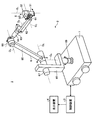
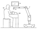
- FIG. 1 is a perspective view illustrating an external configuration of a medical observation system according to Embodiment 1 of the present disclosure.
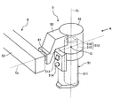
- FIG. 2 is an enlarged perspective view illustrating a configuration of a microscope unit and its periphery of the medical observation apparatus according to the first embodiment of the present disclosure.
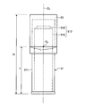
- FIG. 3 is a diagram illustrating a configuration of a main part of the medical observation apparatus according to the first embodiment of the present disclosure.
- FIG. 4 is a diagram schematically illustrating a situation in which the user operates the microscope unit of the medical observation apparatus according to the first embodiment of the present disclosure.
- FIG. 5 is a diagram schematically illustrating a state of an operation performed using the medical observation system according to Embodiment 1 of the present disclosure.
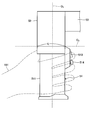
- FIG. 6 is a partial cross-sectional view illustrating a configuration of a main part of the medical observation apparatus according to the second embodiment of the present disclosure.
- FIG. 1 is a diagram illustrating a configuration of a medical observation system according to Embodiment 1 of the present disclosure.
- the medical observation system 1 shown in FIG. 1 includes a medical observation apparatus (hereinafter referred to as an observation apparatus) 2 having a function as a microscope for enlarging and imaging a fine structure of an object to be observed, and the operation of the medical observation system 1. And a display device 4 that displays an image captured by the observation device 2.
- an observation apparatus hereinafter referred to as an observation apparatus 2 having a function as a microscope for enlarging and imaging a fine structure of an object to be observed
- a display device 4 that displays an image captured by the observation device 2.
- the observation device 2 is connected to an observation unit 5 for observing a minute part of the object to be observed, a base end portion of the observation unit 5, and a support unit 6 that supports the observation unit 5 so as to be rotatable, And a base portion 7 that holds the end portion rotatably and can move on the floor surface.
- FIG. 2 is an enlarged perspective view showing the structure of the observation unit 5 and its surroundings.
- FIG. 3 is a side view in the direction of arrow A in FIG.
- the arrow A direction is a direction orthogonal to the first axis O 1 of FIG. 2 and parallel to the second axis O 2 .
- the configuration of the observation unit 5 will be described with reference to FIGS. 2 and 3.
- Observation unit 5 a first joint for holding a microscope unit 51 for imaging an enlarged microscopic sites of the observed body, pivotably microscope 51 about the first axis O 1 of the height direction at the tip end Part 52 and a first arm part 53 for fixing and holding the first joint part 52 on the distal end side.
- the microscope unit 51 includes a cylindrical part 511 having a cylindrical shape, an imaging part 512 that is provided in a hollow part of the cylindrical part 511, and that magnifies an image of the object to be observed, a first arm part 53, and a support part.
- 6 includes an arm operation switch 513 that receives an operation input that allows movement of an arm unit (described later) of the image pickup unit 6, and a cross lever 514 that can change an enlargement magnification in the imaging unit 512 and a focal length to the object to be observed.
- the microscope unit 51 has a column shape that is gripped by the user when the microscope unit 51 moves.
- the cylindrical part 511 has a cylindrical shape with a diameter smaller than that of the first joint part 52, and a cover glass that protects the imaging part 512 is provided on the opening surface of the lower end that collects light from the object to be observed. (Not shown). Note that the shape of the cylindrical portion 511 is not limited to a cylindrical shape, and may be a polygonal cylindrical shape.
- the imaging unit 512 has a plurality of lenses that are respectively arranged so that the optical axis coincides with the first axis O 1, and an optical system 515 that focuses and collects light from the object to be observed, and an optical system
- the image sensor 516 generates image signals by receiving light collected by the light 515 and performing photoelectric conversion. Note that FIG. 2 shows only a cylindrical housing that houses a plurality of lenses included in the optical system 515.
- the optical system 515 can change the magnification of the observed object image and the focal length to the observed object in accordance with the operation of the cross lever 514.
- the image sensor 516 is configured using a CCD (Charge Coupled Device) or a CMOS (Complementary Metal Oxide Semiconductor).
- the image sensor 516 generates and outputs an image signal. This imaging signal is transmitted to the control device 3 via a transmission cable provided inside the support portion 6.
- the imaging unit 512 has entered the first joint unit 52.
- the optical system 515 and the image sensor 516 installed in the hollow portion of the cylindrical portion 511 and the first joint portion 52 are schematically shown by a one-dot chain line.
- the boundary of the portion of the microscope unit 51 that enters the first joint portion 52 and rotates with the cylindrical portion 511 with respect to the first joint portion 52 is schematically shown by a two-dot chain line. Yes.
- the arm operation switch 513 is a push button type switch. While the user presses down the arm operation switch 513, the first joint portion 52 and the second joint portion 61, the third joint portion 63, the fourth joint portion 65, the fifth joint portion 67, and the fifth joint portion of the support portion 6 are provided. The electromagnetic brake of the six joints 69 is released.
- the arm operation switch 513 is provided on the side opposite to the side facing the user when operating the microscope unit 51, in other words, on the side serving as the blind spot of the user when operating the microscope unit 51.
- the arm operation switch 513 forms a part of an input unit that receives an operation instruction input to the microscope unit 51.
- the cross lever 514 can be operated along the height direction of the cylindrical portion 511 and the circumferential direction orthogonal to the height direction.
- the cross lever 514 is provided on the side surface of the cylindrical portion 511 and on the lower side surface of the arm operation switch 513 along the height direction of the cylindrical portion 511.
- the cross lever 514 also forms a part of an input unit that receives an operation instruction input to the microscope unit 51.
- the enlargement magnification is changed.
- the focal length to the object to be observed is changed. For example, when the cross lever 514 is moved upward along the height direction of the tubular portion 511, the enlargement magnification increases, and when the cross lever 514 is moved downward along the height direction of the tubular portion 511, the enlargement magnification decreases. Become.
- the focal distance to the object to be observed is increased, and the cross lever 514 is rotated counterclockwise along the circumferential direction of the cylindrical portion 511. When it is moved, the focal distance to the object to be observed becomes closer. Note that the movement direction and operation assignment of the cross lever 514 are not limited to those described here.
- the first joint portion 52 holds the microscope portion 51 rotatably at the distal end side, and is held by the first arm portion 53 while being fixed to the distal end portion of the first arm portion 53 at the proximal end side.
- the first joint portion 52 has a cylindrical shape, and holds the microscope portion 51 so as to be rotatable around a first axis O 1 that is a central axis in the height direction.
- the first arm portion 53 extends from the upper end portion of the side surface of the first joint portion 52 in a direction orthogonal to the first axis O 1 and parallel to the second axis O 2, and changes its direction in the oblique direction to the second axis. It has a substantially L shape extending so as to gradually approach O 2 .
- the center of gravity G of the observation unit 5 having the above configuration is located at the intersection of the first axis O 1 and the second axis O 2 as shown in FIG.
- the second axis O 2 passes through the boundary between the cylindrical portion 511 and the first joint portion 52 of the microscope unit 51.
- the two heights H and h can be expressed by the relation H / 2 ⁇ h ⁇ 2H. / 3 is satisfied.
- the center of gravity G is located farther from the lower end of the microscope unit 51 than the center of the height in the direction of the first axis O 1 and the input unit (arm operation switch 513, cross lever 514).
- the center of gravity G may be located near the intersection of the first axis O 1 and the second axis O 2 as long as the above relational expression is satisfied, and is located closer to the intersection from the lower end of the microscope unit 51. If so, it is more preferable.
- the vicinity of the intersection of the first axis O 1 and the second axis O 2 means that the diameter of the boundary portion between the microscope unit 51 and the first joint unit 52 is L (see FIG. 3 and FIG. 4 described later). ),
- the outer contour of the first joint portion 52 is configured using a material having a relatively large specific gravity such as brass or a super hard alloy, while the outer contour of the cylindrical portion 511 is A material having a relatively small specific gravity such as aluminum is used.
- the support portion 6 includes a second joint portion 61, a second arm portion 62, a third joint portion 63, a third arm portion 64, a fourth joint portion 65, a fourth arm portion 66, a fifth joint portion 67, and a fifth arm. Part 68 and sixth joint part 69.
- the support portion 6 has three sets of two arm portions and a set of joint portions that rotatably connect one (tip end side) of the two arm portions to the other (base end side). Specifically, these three sets are (second arm part 62, third joint part 63, third arm part 64), (third arm part 64, fourth joint part 65, fourth arm part 66), (4th arm part 66, 5th joint part 67, 5th arm part 68).
- the second joint portion 61 rotatably holds the first arm portion 53 on the distal end side, and is held by the second arm portion 62 in a state of being fixed to the distal end portion of the second arm portion 62 on the proximal end side.
- the Second joint 61 has a cylindrical shape, holding the first arm portion 53 rotatably about the second axis O 2.
- the second arm portion 62 is substantially L-shaped, and is connected to the second joint portion 61 at the end of the L-shaped vertical line portion.
- the third joint portion 63 holds the L-shaped horizontal line portion of the second arm portion 62 rotatably on the distal end side, and is fixed to the distal end portion of the third arm portion 64 on the proximal end side. It is held by the arm part 64.
- the third joint part 63 has a cylindrical shape, is an axis orthogonal to the second axis O 2 , and rotates around the third axis O 3 , which is an axis parallel to the direction in which the second arm part 62 extends.
- the 2nd arm part 62 is hold
- the distal end side of the third arm portion 64 has a cylindrical shape, and a hole portion penetrating in the direction orthogonal to the height direction of the distal end side cylinder is formed on the proximal end side.
- the third joint portion 63 is rotatably held by the fourth joint portion 65 through the hole.
- the fourth joint portion 65 rotatably holds the third arm portion 64 at the distal end side, and is held by the fourth arm portion 66 in a state of being fixed to the fourth arm portion 66 at the proximal end side.
- the fourth joint portion 65 has a cylindrical shape, and holds the third arm portion 64 so as to be rotatable around a fourth axis O 4 that is an axis orthogonal to the third axis O 3 .
- the fifth joint portion 67 rotatably holds the fourth arm portion 66 on the distal end side, and is fixedly attached to the fifth arm portion 68 on the proximal end side.
- the fifth joint portion 67 has a cylindrical shape, and holds the fourth arm portion 66 rotatably around a fifth axis O 5 that is an axis parallel to the fourth axis O 4 .
- the fifth arm portion 68 includes an L-shaped portion and a rod-shaped portion extending downward from the L-shaped horizontal line portion.
- the fifth joint portion 67 is attached to the end portion of the L-shaped vertical line portion of the fifth arm portion 68 on the proximal end side.
- the sixth joint portion 69 rotatably holds the fifth arm portion 68 on the distal end side, and is fixedly attached to the upper surface of the base portion 7 on the proximal end side.
- the sixth joint portion 69 has a cylindrical shape, and holds the fifth arm portion 68 rotatably around a sixth axis O 6 that is an axis orthogonal to the fifth axis O 5 .
- a proximal end portion of a bar-shaped portion of the fifth arm portion 68 is attached to the distal end side of the sixth joint portion 69.
- the support unit 6 having the above-described configuration realizes a total of 6 degrees of freedom of movement in the microscope unit 51 including 3 translational degrees of freedom and 3 degrees of freedom of rotation.
- 1st joint part 52, 2nd joint part 61, 3rd joint part 63, 4th joint part 65, 5th joint part 67 And the sixth joint 69 are electromagnetic brakes that prohibit the rotation of the microscope 51, the first arm 53, the second arm 62, the third arm 64, the fourth arm 66, and the fifth arm 68, respectively.
- Have Each electromagnetic brake is released in a state where an arm operation switch 513 provided in the microscope unit 51 is pressed, and the microscope unit 51, the first arm unit 53, the second arm unit 62, the third arm unit 64, and the fourth arm unit. 66 and the fifth arm portion 68 are allowed to rotate.
- An air brake may be applied instead of the electromagnetic brake.
- FIG. 4 is a diagram schematically showing a situation where the user operates the microscope unit 51.
- the user faces the microscope unit 51 facing the side surface (the left side surface in FIG. 4) opposite to the side surface (the right side surface in FIG. 4) on which the arm operation switch 513 and the cross lever 514 are provided.
- the user operates the support unit 6 while pressing the arm operation switch 513 with the index finger (or middle finger or ring finger) while holding the microscope unit 51 with the right hand 101.
- the user can operate the support unit 6 by pressing the arm operation switch 513 while naturally holding the microscope unit 51.
- the cylindrical portion 511 can have a sufficient height. According to the observation unit 5 having such a shape, it is easy for the user to hold and the rotation operation around the first axis O 1 and the second axis O 2 can be easily performed.
- the arm operation switch 513 is provided on the side surface of the microscope unit 51 that is the blind spot of the user (the side surface opposite to the side facing the user), the user holds the microscope unit 51 with his / her hand. Even if the microscope unit 51 is rotated or tilted, an operation of continuously pressing the arm operation switch 513 and an operation of pressing or releasing the arm operation switch 513 can be performed without a sense of incongruity.
- the user grasps the periphery of the microscope unit 51 with his / her hand, the user can intuitively recognize the direction of the optical axis of the optical system 515 or the imaging field of view of the microscope unit 51, and easily move the microscope unit 51 to a desired position. Can be moved.
- the control device 3 generates display image data by performing predetermined signal processing on the imaging signal output by the observation device 2.
- the control device 3 is configured using a CPU (Central Processing Unit), a ROM (Read Only Memory), a RAM (Random Access Memory), and the like.
- the control device 3 may be installed inside the base portion 7 and integrated with the observation device 2.
- the display device 4 receives the image data generated by the control device 3 from the control device 3, and displays an image corresponding to the image data.
- a display device 4 includes a display panel made of liquid crystal or organic EL (Electro Luminescence).
- FIG. 5 is a diagram schematically showing the state of surgery using the medical observation system 1.
- FIG. 5 is a diagram schematically showing a situation in which the surgeon 201 as a user is operating the head of a patient 202 as an object to be observed. While viewing the image displayed on the display device 4, the surgeon 201 holds the microscope unit 51 while moving the arm operation switch 513 of the microscope unit 51 and moves the microscope unit 51 to a desired position. Is determined, the finger is released from the arm operation switch 513.
- an electromagnetic brake operates in the first joint part 52, the second joint part 61, the third joint part 63, the fourth joint part 65, the fifth joint part 67, and the sixth joint part 69.
- the field of view is fixed. Thereafter, the operator 201 adjusts the enlargement magnification and the focal distance to the object to be observed.
- the outer diameter of the cylindrical portion 511 is reduced. More preferably, it is about 40 to 70 mm, and the height of the observation part 5 (H in FIG. 3) is about 80 to 200 mm.
- the microscope unit 51 that collects the light from the object to be observed through one end in the height direction and captures an enlarged image of the minute part of the object to be observed.
- the distance between the center of gravity G of the observation unit 5 and the lower end of the microscope unit 51 is larger than 1 ⁇ 2 of the height of the observation unit and 2/3 of the height of the observation unit. Therefore, the overall size can be sufficiently reduced while securing a portion that the user holds during operation.
- the user grasps and holds the cylindrical portion 511 of the microscope unit 51 with his / her hand, the user intuitively recognizes the direction of the optical axis of the optical system 515 or the imaging field of view of the microscope unit 51.
- the microscope unit 51 can be easily moved to a desired position. This is compared to the case where the grip provided with the operation signal input switch is separated from the optical axis of the optical system and the direction of the optical axis cannot be intuitively recognized as in a conventional surgical microscope. This is one of the very advantageous effects.
- the support unit 6 is configured by connecting a plurality of arm units and joint units, various configurations in the observation unit 5 can be achieved with a simple configuration compared to a conventional link mechanism. Can be realized.
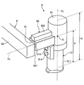
- FIG. 6 is an enlarged perspective view illustrating a configuration of a main part of an observation apparatus included in the medical observation system according to Embodiment 2 of the present disclosure.
- the configuration of the observation unit 9 is different from that of the observation unit 5 of the first embodiment.
- the configuration other than the observation unit 5 is the same as the configuration of the medical observation system 1 described in the first embodiment.
- the observation unit 9 includes a microscope unit 51, a first joint unit 91, and a first arm unit 92.
- the microscope unit 51 includes the cylindrical unit 511, the imaging unit 512, the arm operation switch 513, and the cross lever 514 (see FIGS. 2 and 3).
- the first joint portion 91 has a cylindrical shape, and holds the microscope portion 51 rotatably around the first axis O 1 on the distal end side, and is fixed to the distal end portion of the first arm portion 92 on the proximal end side. In this state, the first arm 92 is held.
- the first arm portion 92 has a columnar shape extending along the second axis O 2 from the side surface of the first joint portion 91.
- the first arm portion 92 includes a rectangular parallelepiped main body portion 921 that is rotatably held around the second axis O 2 by the second joint portion 61 on the proximal end side, and the microscope portion 51 among the side surfaces of the main body portion 921.
- a cable housing portion 922 that houses a plurality of transmission cables that transmit signals between the microscope unit 51 and the control device 3.
- the cable storage portion 922 is configured using a material having a relatively large specific gravity such as brass or a super hard alloy.
- the first arm portion 92 has a specific gravity of the first portion located on the lower end side of the microscope portion 51 with respect to a plane passing through the second axis O 2 and orthogonal to the first axis O 1.
- the specific gravity of the second portion including the cable storage portion 922 is smaller than that of the second portion.
- the two heights H ′ and h ′ are expressed by the relation H ′ / 2 ⁇ h ′ ⁇ 2H ′ / 3 is satisfied.
- the center of gravity G may be located near the intersection of the first axis O 1 and the second axis O 2 as long as the above relational expression is satisfied, and is located closer to the intersection from the lower end of the microscope unit 51. If so, it is more preferable.
- the microscope unit 51 can be easily moved to a desired position.
- the cable storage portion 922 made of a material having a relatively large specific gravity is provided on the side surface far from the lower end of the microscope portion 51 with respect to the main body portion 921 of the first arm portion 92. Accordingly, the specific gravity of the first portion located on the lower end side of the microscope unit 51 is located on the opposite side with respect to the plane that passes through the second axis O 2 and is orthogonal to the first axis O 1. The specific gravity of the second portion including 922 is smaller. Accordingly, the center of gravity G of the observation unit 9 can be positioned farther from one end of the microscope unit 51 and the input unit than the center of the height of the observation unit 9 in the first axis O 1 direction. Can be improved. In addition, since the cable storage portion 922 has both a cable storage function and a weight function, it is possible to reduce design waste as compared with the case where each is provided individually.
- the support part 6 should just have at least 1 set which consists of a joint part which connects two arm parts and one of these two arm parts so that rotation with respect to the other is possible.
- the operation input unit provided in the cylindrical part 511 is not limited to the above-described one.
- an operation unit for changing the magnification and an operation unit for changing the focal distance to the object to be observed may be provided separately.
- a microscope unit that collects light from an object to be observed through one end in the height direction and captures an enlarged image of a minute part of the object to be observed.
- An observation part having a center of gravity and being located farther from the one end than the center in the height direction,
- a support unit that rotatably supports the observation unit around an axis perpendicular to the height direction through the center of gravity or the vicinity of the center of gravity; Comprising Medical observation device.
- the observation unit is The distance between the center of gravity and the one end is greater than 1 ⁇ 2 of the height of the observation part and not more than 2/3 of the height of the observation part.
- the observation unit is A first joint portion that rotatably holds the microscope portion around a first axis along the height direction; In a mode in which the first joint portion is held at the distal end portion and is rotatable around a second axis which is an axis perpendicular to the height direction and orthogonal to the first axis at the proximal end portion.
- the first arm portion is The specific gravity of the first portion located on the one end side with respect to the plane that passes through the second axis and is orthogonal to the first axis is that of the second portion that is located on the opposite side of the first portion with respect to the plane. Smaller than the specific gravity, The medical observation apparatus according to (3) above.
- the observation unit is Provided on a side surface of the microscope unit, located near the one end than the center of gravity, further having an input unit for receiving an operation instruction input to the microscope unit; The medical observation apparatus according to any one of (1) to (4).
- the support part is Having at least one set of two arm portions and a joint portion that rotatably connects one of the two arm portions to the other;
- the medical observation apparatus according to any one of (1) to (5).
- the medical observation apparatus according to any one of (1) to (6), A control device that generates image data for display by performing signal processing on the imaging signal output by the medical observation device;
- a display device for displaying an image corresponding to the image data generated by the control device; Comprising Medical observation system.
Landscapes
- Physics & Mathematics (AREA)
- Health & Medical Sciences (AREA)
- Surgery (AREA)
- General Physics & Mathematics (AREA)
- Optics & Photonics (AREA)
- General Health & Medical Sciences (AREA)
- Life Sciences & Earth Sciences (AREA)
- Chemical & Material Sciences (AREA)
- Analytical Chemistry (AREA)
- Engineering & Computer Science (AREA)
- Pathology (AREA)
- Oral & Maxillofacial Surgery (AREA)
- Nuclear Medicine, Radiotherapy & Molecular Imaging (AREA)
- Biomedical Technology (AREA)
- Heart & Thoracic Surgery (AREA)
- Medical Informatics (AREA)
- Molecular Biology (AREA)
- Animal Behavior & Ethology (AREA)
- Public Health (AREA)
- Veterinary Medicine (AREA)
- Microscoopes, Condenser (AREA)
- Multimedia (AREA)
- Computer Vision & Pattern Recognition (AREA)
Abstract
被観察体からの光を高さ方向の一端を介して集光して該被観察体の微小部位の拡大画像を撮像する顕微鏡であって移動する際にユーザによって把持される柱状をなす顕微鏡部を有し、重心が高さ方向の中心よりも一端から遠くに位置する観察部と、観察部を、重心または該重心の近傍を通過して高さ方向と垂直な軸のまわりに回動可能に支持する支持部とを備えるように構成し、操作性に優れて小型化にも好適な医療用観察装置および医療用観察システムを提供する。
Description
本開示は、被観察体の微小部位を観察する医療用観察装置および医療用観察システムに関する。
従来、被観察体である患者の脳や心臓等における微小部位の手術を行う際に該微小部位を観察するための技術として、該微小部位を撮像し、撮像した画像をモニタで表示する技術が知られている。
例えば、特許文献1では、対物光学系を有する観察装置と、この対物光学系に入射した光学像を撮像する撮像装置と、観察装置および撮像装置を保持して連動させる移動機構とを備えた観察システムが開示されている。
また、特許文献2には、対物光学系、撮像光学系、およびそれら2つの光学系の間に設けられる変倍光学系を有し、変倍光学系が折り曲げ光学系として構成されるC字状の鏡体部と、この鏡体部を移動可能に支持する支持手段とを備えた医療用観察装置が開示されている。
医療用の観察装置では、操作のしやすさに対する要求と同時に、ユーザである術者の視野を確保したり省スペース化を実現したりするために装置の小型化に関する要求も強くなってきている。しかしながら、上述した特許文献1、2では、観察および撮像機能を有する先端部または鏡体部を移動させる機構がリンク機構等を用いて構成されるため、構造が複雑で大がかりにならざるを得ず、その先端部または鏡体部を操作する際の操作性が良好であるとは言い難かった。また、特許文献2の場合、鏡体部の構成自体も小型化する上での障害となっていた。
本開示は、上記に鑑みてなされたものであって、操作性に優れて小型化にも好適な医療用観察装置および医療用観察システムを提供することを目的とする。
上述した課題を解決し、目的を達成するために、本開示に係る医療用観察装置は、被観察体からの光を高さ方向の一端を介して集光して該被観察体の微小部位の拡大画像を撮像する顕微鏡部であって移動する際にユーザによって把持される柱状をなす顕微鏡部を有し、重心が前記高さ方向の中心よりも前記一端から遠くに位置する観察部と、前記観察部を、前記重心または該重心の近傍を通過して前記高さ方向と垂直な軸のまわりに回動可能に支持する支持部と、を備えたことを特徴とする。
当該医療用観察装置においては、前記観察部は、前記重心と前記一端との距離が、前記観察部の高さの1/2より大きく、かつ前記観察部の高さの2/3以下であってもよい。
当該医療用観察装置においては、前記観察部は、前記顕微鏡部を前記高さ方向に沿った第1軸のまわりに回動可能に保持する第1関節部と、先端部で前記第1関節部を保持するとともに、基端部で前記高さ方向と垂直な軸であって前記第1軸と直交する軸である第2軸のまわりに回動可能な態様で前記支持部に保持される第1アーム部と、をさらに有し、前記重心は、前記第1軸と前記第2軸の交点に位置する、または該交点より前記一端から近くに位置してもよい。
当該医療用観察装置においては、前記第1アーム部は、前記第2軸を通過するとともに前記第1軸と直交する平面に対して前記一端側に位置する第1部分の比重が前記平面に対して前記第1部分と反対側に位置する第2部分の比重より小さくてもよい。
当該医療用観察装置においては、前記観察部は、前記顕微鏡部の側面に設けられ、前記重心よりも前記一端の近くに位置し、前記顕微鏡部に対する動作指示の入力を受け付ける入力部をさらに有してもよい。
当該医療用観察装置においては、前記支持部は、2つのアーム部および該2つのアーム部の一方を他方に対して回動可能に連結する関節部からなる組を少なくとも一組有してもよい。
本開示に係る医療用観察システムは、上記に記載の医療用観察装置と、前記医療用観察装置が出力した撮像信号に対して信号処理を施して表示用の画像データを生成する制御装置と、前記制御装置が生成した画像データに対応する画像を表示する表示装置と、を備えたことを特徴とする。
本開示によれば、被観察体からの光を高さ方向の一端を介して集光して該被観察体の微小部位の拡大画像を撮像する顕微鏡部であって移動する際にユーザによって把持される柱状をなす顕微鏡部を有し、重心が高さ方向の中心よりも一端から遠くに位置する観察部と、観察部を重心または該重心の近傍を通過して高さ方向と垂直な軸のまわりに回動可能に支持する支持部と、を備えるため、観察部を大きくすることなく、ユーザが把持する部分を十分に確保することができる。したがって、操作性に優れて小型化にも好適な医療用観察装置および医療用観察システムを提供することができる。
以下、添付図面を参照して、本開示を実施するための形態(以下、「実施の形態」という)を説明する。なお、図面はあくまで模式的なものであり、図面の相互間においても互いの寸法の関係や比率が異なる部分が含まれる場合がある。
(実施の形態1)
図1は、本開示の実施の形態1に係る医療用観察システムの構成を示す図である。同図に示す医療用観察システム1は、被観察体の微細構造を拡大して撮像する顕微鏡としての機能を有する医療用観察装置(以下、観察装置という)2と、医療用観察システム1の動作を統括して制御する制御装置3と、観察装置2が撮像した画像を表示する表示装置4とを備える。
図1は、本開示の実施の形態1に係る医療用観察システムの構成を示す図である。同図に示す医療用観察システム1は、被観察体の微細構造を拡大して撮像する顕微鏡としての機能を有する医療用観察装置(以下、観察装置という)2と、医療用観察システム1の動作を統括して制御する制御装置3と、観察装置2が撮像した画像を表示する表示装置4とを備える。
観察装置2は、被観察体の微小部位を観察する観察部5と、観察部5の基端部に接続し、観察部5を回動可能に支持する支持部6と、支持部6の基端部を回動可能に保持し、床面上を移動可能なベース部7と、を有する。
図2は、観察部5とその周辺の構成を示す拡大斜視図である。図3は、図2の矢視A方向の側面図である。矢視A方向は、図2の第1軸O1と直交するとともに第2軸O2と平行な方向である。以下、図2および図3を参照して、観察部5の構成を説明する。
観察部5は、被観察体の微小部位を拡大して撮像する顕微鏡部51と、先端側で顕微鏡部51を高さ方向の第1軸O1のまわりに回動可能に保持する第1関節部52と、先端側で第1関節部52を固定して保持する第1アーム部53とを有する。
顕微鏡部51は、円筒状をなす筒状部511と、筒状部511の中空部に設けられ、被観察体の像を拡大して撮像する撮像部512と、第1アーム部53および支持部6が有するアーム部(後述)の動きを許容する操作入力を受け付けるアーム操作スイッチ513と、撮像部512における拡大倍率および被観察体までの焦点距離を変更可能な十字レバー514と、を有する。顕微鏡部51は、自身が移動する際にユーザによって把持される柱状をなしている。
筒状部511は、第1関節部52よりも径が小さい円筒状をなしており、被観察体からの光を集光する下端の開口面には、撮像部512を保護するカバーガラスが設けられている(図示せず)。なお、筒状部511の形状は円筒状に限られるわけではなく、多角筒状であってもよい。
撮像部512は、光軸が第1軸O1と一致するようにそれぞれ配置される複数のレンズを有し、被観察体からの光を集光して結像する光学系515と、光学系515が集光した光を受光して光電変換することによって撮像信号をそれぞれ生成する撮像素子516とを有する。なお、図2では、光学系515が有する複数のレンズを収容する筒状の筐体のみを記載している。
光学系515は、十字レバー514の操作に応じて被観察体像の拡大倍率および被観察体までの焦点距離を変更可能である。
撮像素子516は、CCD(Charge Coupled Device)またはCMOS(Complementary Metal Oxide Semiconductor)を用いて構成される。撮像素子516は、撮像信号を生成して出力する。この撮像信号は、支持部6の内部に設けられる伝送ケーブルを介して制御装置3に伝送される。
撮像部512は、第1関節部52の内部まで入り込んでいる。図3では、筒状部511および第1関節部52の中空部に設置される光学系515および撮像素子516を1点鎖線で模式的に示している。また、図3では、顕微鏡部51のうち第1関節部52の内部に入り込んで第1関節部52に対して筒状部511とともに回動する部分の境界を2点鎖線で模式的に示している。
アーム操作スイッチ513は、押しボタン式のスイッチである。ユーザがアーム操作スイッチ513を押下している間、第1関節部52、ならびに支持部6が有する第2関節部61、第3関節部63、第4関節部65、第5関節部67および第6関節部69の電磁ブレーキが解除される。アーム操作スイッチ513は、顕微鏡部51の操作時にユーザが向かい合う側面と反対側の側面、換言すると顕微鏡部51の操作時にユーザの死角となる側面に設けられる。アーム操作スイッチ513は、顕微鏡部51に対する動作指示の入力を受け付ける入力部の一部をなす。
十字レバー514は、筒状部511の高さ方向および該高さ方向と直交する周方向に沿って操作可能である。十字レバー514は、筒状部511の側面であって筒状部511の高さ方向に沿ってアーム操作スイッチ513の下方の側面に設けられる。十字レバー514も、アーム操作スイッチ513と同様に、顕微鏡部51に対する動作指示の入力を受け付ける入力部の一部をなす。
十字レバー514を図2に示す状態から筒状部511の高さ方向に沿って操作すると、拡大倍率が変更される。また、十字レバー514を図2に示す状態から筒状部511の周方向に沿って操作すると、被観察体までの焦点距離が変更される。例えば、筒状部511の高さ方向に沿って十字レバー514を上方へ動かすと拡大倍率が大きくなり、筒状部511の高さ方向に沿って十字レバー514を下方へ動かすと拡大倍率が小さくなる。また、筒状部511の周方向に沿って十字レバー514を時計回りに動かすと被観察体までの焦点距離が遠くなり、筒状部511の周方向に沿って十字レバー514を反時計回りに動かすと被観察体までの焦点距離が近くなる。なお、十字レバー514の移動方向と操作の割り当ては、ここで説明したものに限られるわけではない。
第1関節部52は、先端側で顕微鏡部51を回動可能に保持するとともに、基端側で第1アーム部53の先端部に固定された状態で第1アーム部53に保持される。第1関節部52は円筒状をなし、高さ方向の中心軸である第1軸O1のまわりに回動可能に顕微鏡部51を保持する。
第1アーム部53は、第1関節部52の側面上端部から第1軸O1と直交するとともに第2軸O2と平行な方向に延び、途中で斜め方向に向きを変えて第2軸O2へ徐々に近づくように延びる略L字状をなす。
以上の構成を有する観察部5の重心Gは、図2に示すように第1軸O1と第2軸O2の交点に位置している。第2軸O2は、顕微鏡部51の筒状部511と第1関節部52との境界を通過する。観察部5の高さをHとし、顕微鏡部51における集光側である下端から重心Gまでの高さをhとすると、2つの高さHおよびhは、関係式H/2<h≦2H/3を満たす。換言すれば、重心Gは、顕微鏡部51の下端に対して第1軸O1の方向の高さの中心および入力部(アーム操作スイッチ513、十字レバー514)よりも遠くに位置している。なお、重心Gは、上記関係式を満たしていれば、第1軸O1と第2軸O2の交点の近傍に位置していてもよく、顕微鏡部51の下端から交点よりも近くに位置していればより好ましい。ここで、第1軸O1と第2軸O2の交点の近傍とは、顕微鏡部51と第1関節部52の境界部分の径をLとするとき(図3および後述する図4を参照)、その交点を中心とする半径L/2の球状領域のことであり、より好ましくは、その交点を中心とする半径L/4の球状領域のことであり、さらに好ましくは、その交点を中心とする半径L/8の球状領域のことである。
以上の構成を有する観察部5において、例えば、第1関節部52の外郭は、真鍮または超硬質合金等の比較的比重が大きい材料を用いて構成される一方、筒状部511の外郭は、アルミニウム等の比較的比重が小さい材料を用いて構成される。
次に、図1を参照して支持部6の構成を説明する。支持部6は、第2関節部61、第2アーム部62、第3関節部63、第3アーム部64、第4関節部65、第4アーム部66、第5関節部67、第5アーム部68、および第6関節部69を有する。支持部6は、2つのアーム部および2つのアーム部の一方(先端側)を他方(基端側)に対して回動可能に連結する関節部からなる組を3組有する。この3組は、具体的には、(第2アーム部62、第3関節部63、第3アーム部64)、(第3アーム部64、第4関節部65、第4アーム部66)、(第4アーム部66、第5関節部67、第5アーム部68)である。
第2関節部61は、先端側で第1アーム部53を回動可能に保持するとともに、基端側で第2アーム部62の先端部に固定された状態で第2アーム部62に保持される。第2関節部61は円筒状をなしており、第2軸O2のまわりに回動可能に第1アーム部53を保持する。第2アーム部62は略L字状をなし、L字の縦線部分の端部で第2関節部61に連結する。
第3関節部63は、先端側で第2アーム部62のL字の横線部分を回動可能に保持するとともに、基端側で第3アーム部64の先端部に固定された状態で第3アーム部64に保持される。第3関節部63は、円筒状をなしており、第2軸O2と直交する軸であり、かつ第2アーム部62が延びる方向と平行な軸である第3軸O3のまわりに回動可能に第2アーム部62を保持する。第3アーム部64は先端側が円筒状をなしており、基端側に先端側の円筒の高さ方向と直交する方向に貫通する孔部が形成されている。第3関節部63は、この孔部を介して第4関節部65に回動可能に保持される。
第4関節部65は、先端側で第3アーム部64を回動可能に保持するとともに、基端側で第4アーム部66に固定された状態で第4アーム部66に保持される。第4関節部65は円筒状をなしており、第3軸O3と直交する軸である第4軸O4のまわりに回動可能に第3アーム部64を保持する。
第5関節部67は、先端側で第4アーム部66を回動可能に保持するとともに、基端側で第5アーム部68に固定して取り付けられる。第5関節部67は円筒状をなしており、第4軸O4と平行な軸である第5軸O5のまわりに第4アーム部66を回動可能に保持する。第5アーム部68は、L字状をなす部分と、L字の横線部分から下方へ延びる棒状の部分とからなる。第5関節部67は、基端側で第5アーム部68のL字の縦線部分の端部に取り付けられる。
第6関節部69は、先端側で第5アーム部68を回動可能に保持するとともに、基端側でベース部7の上面に固定して取り付けられる。第6関節部69は円筒状をなしており、第5軸O5と直交する軸である第6軸O6のまわりに第5アーム部68を回動可能に保持する。第6関節部69の先端側には、第5アーム部68の棒状の部分の基端部が取り付けられる。
以上説明した構成を有する支持部6は、顕微鏡部51における並進3自由度および回転3自由度の計6自由度の動きを実現する。
第1関節部52、第2関節部61、第3関節部63、第4関節部65、第5関節部67
および第6関節部69は、顕微鏡部51、第1アーム部53、第2アーム部62、第3アーム部64、第4アーム部66および第5アーム部68の回動をそれぞれ禁止する電磁ブレーキを有する。各電磁ブレーキは、顕微鏡部51に設けられるアーム操作スイッチ513が押下された状態で解除され、顕微鏡部51、第1アーム部53、第2アーム部62、第3アーム部64、第4アーム部66および第5アーム部68の回動を許容する。なお、電磁ブレーキの代わりにエアブレーキを適用してもよい。
および第6関節部69は、顕微鏡部51、第1アーム部53、第2アーム部62、第3アーム部64、第4アーム部66および第5アーム部68の回動をそれぞれ禁止する電磁ブレーキを有する。各電磁ブレーキは、顕微鏡部51に設けられるアーム操作スイッチ513が押下された状態で解除され、顕微鏡部51、第1アーム部53、第2アーム部62、第3アーム部64、第4アーム部66および第5アーム部68の回動を許容する。なお、電磁ブレーキの代わりにエアブレーキを適用してもよい。
図4は、ユーザが顕微鏡部51を操作する状況を模式的に示す図である。ユーザは、筒状部511の側面のうち、アーム操作スイッチ513および十字レバー514が設けられる側面(図4の右側面)と反対側の側面(図4の左側面)に対向して顕微鏡部51を操作する。この際、ユーザは、顕微鏡部51を右手101で把持した状態で、アーム操作スイッチ513を人差し指(または中指または薬指)で押下しながら支持部6を操作する。
このように、ユーザは顕微鏡部51を自然に握ったままアーム操作スイッチ513を押下して支持部6を操作することができる。特に、観察部5における重心Gの位置が観察部5の高さ方向の中心よりも顕微鏡部51の下端から遠くに位置しているため、筒状部511の高さを十分取ることができる。このような形状を有する観察部5によれば、ユーザが把持しやすく、かつ第1軸O1および第2軸O2のまわりの回動操作を容易に行うことが可能となる。
また、アーム操作スイッチ513が、顕微鏡部51の側面のうちユーザの死角となる側面(ユーザが向い合う側面と反対側の側面)に設けられるため、ユーザは顕微鏡部51を手で握った状態で、顕微鏡部51を回転したり傾斜させたりしても、アーム操作スイッチ513を押し続ける操作や、アーム操作スイッチ513を押したり離したりする操作を違和感なく行うことができる。
さらに、ユーザは顕微鏡部51の周囲を手で握るため、光学系515の光軸の方向または顕微鏡部51の撮像視野を直感的に認識することができ、顕微鏡部51を所望の位置へ容易に移動させることができる。
引き続き、医療用観察システム1の構成を説明する。
制御装置3は、観察装置2が出力した撮像信号に所定の信号処理を施すことによって表示用の画像データを生成する。制御装置3は、CPU(Central Processing Unit)、ROM(Read Only Memory)、RAM(Random Access Memory)等を用いて構成される。なお、制御装置3をベース部7の内部に設置して観察装置2と一体化してもよい。
制御装置3は、観察装置2が出力した撮像信号に所定の信号処理を施すことによって表示用の画像データを生成する。制御装置3は、CPU(Central Processing Unit)、ROM(Read Only Memory)、RAM(Random Access Memory)等を用いて構成される。なお、制御装置3をベース部7の内部に設置して観察装置2と一体化してもよい。
表示装置4は、制御装置3が生成した画像データを制御装置3から受信し、該画像データに対応する画像を表示する。このような表示装置4は、液晶または有機EL(Electro Luminescence)からなる表示パネルを備える。
次に、以上の構成を有する医療用観察システム1を用いて行われる手術の概要を説明する。図5は、医療用観察システム1を用いた手術の状況を模式的に示す図である。具体的には、図5は、ユーザである術者201が被観察体である患者202の頭部を手術している状況を模式的に示す図である。術者201は、表示装置4が表示する画像を目視しながら、顕微鏡部51のアーム操作スイッチ513を押下した状態で顕微鏡部51を把持して所望の位置まで移動させ、顕微鏡部51の撮像視野を決定した後、アーム操作スイッチ513から指を離す。これにより、第1関節部52、第2関節部61、第3関節部63、第4関節部65、第5関節部67および第6関節部69では電磁ブレーキが動作し、顕微鏡部51の撮像視野が固定される。その後、術者201は、拡大倍率および被観察体までの焦点距離の調整等を行う。
術者201が顕微鏡部51を把持しやすく、かつ術者201が表示装置4または患者202の術部を見る際の視界の妨げとならないようにするには、例えば筒状部511の外径が40~70mm程度であり、観察部5の高さ(図3のH)が80~200mm程度であればより好ましい。
以上説明した本開示の実施の形態1によれば、被観察体からの光を高さ方向の一端を介して集光して該被観察体の微小部位の拡大画像を撮像する顕微鏡部51であって移動する際にユーザによって把持される柱状をなす顕微鏡部51を有し、重心Gが高さ方向の中心よりも一端から遠くに位置する観察部5と、観察部5を重心Gまたは該重心Gの近傍を通過して高さ方向と垂直な軸(第2軸O2)のまわりに回動可能に支持する支持部6と、を備えるため、重心Gの位置を観察部5の高さ方向の中心からシフトさせることで、観察部5を大きくすることなく、ユーザが把持する部分を十分に確保することができる。したがって、操作性に優れて小型化にも好適な医療用観察装置および医療用観察システムを提供することができる。
また、本実施の形態1によれば、観察部5の重心Gと顕微鏡部51の下端との距離を、観察部の高さの1/2より大きく、かつ観察部の高さの2/3以下としたため、ユーザが操作時に把持する部分を確保しつつ、全体の大きさを十分に小型化することができる。
また、本実施の形態1によれば、ユーザは顕微鏡部51の筒状部511を手で握って把持するため、光学系515の光軸の方向または顕微鏡部51の撮像視野を直感的に認識することができ、顕微鏡部51を所望の位置へ容易に移動させることができる。この点は、従来の手術用顕微鏡のように、操作信号入力用のスイッチが設けられたグリップが光学系の光軸から離れていて光軸方向を直感的に認識することができない場合と比較して、非常に有利な効果の1つである。
また、本実施の形態1によれば、支持部6を複数のアーム部と関節部を連結して構成しているため、従来のようなリンク機構と比べて簡易な構成で観察部5における多様な動きを実現することができる。
(実施の形態2)
図6は、本開示の実施の形態2に係る医療用観察システムが備える観察装置の要部の構成を示す拡大斜視図である。本実施の形態2に係る医療用観察システムは、観察部9の構成が、実施の形態1の観察部5と異なる。観察部5以外の構成は、実施の形態1で説明した医療用観察システム1の構成と同じである。
図6は、本開示の実施の形態2に係る医療用観察システムが備える観察装置の要部の構成を示す拡大斜視図である。本実施の形態2に係る医療用観察システムは、観察部9の構成が、実施の形態1の観察部5と異なる。観察部5以外の構成は、実施の形態1で説明した医療用観察システム1の構成と同じである。
観察部9は、顕微鏡部51と、第1関節部91と、第1アーム部92とを有する。顕微鏡部51は、実施の形態1で説明したように、筒状部511、撮像部512、アーム操作スイッチ513、および十字レバー514を有する(図2、図3を参照)。
第1関節部91は円筒状をなしており、先端側で顕微鏡部51を第1軸O1のまわりに回動可能に保持するとともに、基端側で第1アーム部92の先端部に固定された状態で第1アーム部92に保持される。
第1アーム部92は、第1関節部91の側面から第2軸O2に沿って延びる柱状をなす。第1アーム部92は、基端側で第2関節部61に第2軸O2のまわりに回動可能に保持される直方体状の本体部921と、本体部921の側面のうち顕微鏡部51の下端から最も遠い側面に設けられ、顕微鏡部51と制御装置3との間で信号を伝送する複数の伝送ケーブルを収納するケーブル収納部922とを有する。ケーブル収納部922は、真鍮または超硬質合金等の比較的比重が大きい材料を用いて構成される。第1アーム部92は、第2軸O2を通過するとともに第1軸O1と直交する平面に対して、顕微鏡部51の下端側に位置する第1部分の比重が、その反対側に位置してケーブル収納部922を含む第2部分の比重より小さい。
観察部9の高さをH’とし、顕微鏡部51の下端から重心Gまでの高さをh’とすると、2つの高さH’およびh’は、関係式H’/2<h’≦2H’/3を満たす。なお、重心Gは、上記関係式を満たしていれば、第1軸O1と第2軸O2の交点の近傍に位置していてもよく、顕微鏡部51の下端から交点よりも近くに位置していればより好ましい。
以上説明した本開示の実施の形態2によれば、実施の形態1と同様、操作性に優れて小型化にも好適な医療用観察装置および医療用観察システムを提供することができる。
また、本実施の形態2によれば、実施の形態1と同様、ユーザが操作時に把持する部分を確保することができるとともに、光学系515の光軸の方向または顕微鏡部51の撮像視野を直感的に認識することができ、顕微鏡部51を所望の位置へ容易に移動させることができる。
また、本実施の形態2によれば、第1アーム部92の本体部921に対して、比較的比重が大きい材料からなるケーブル収納部922を顕微鏡部51の下端から遠い側の側面に設けることにより、第2軸O2を通過するとともに第1軸O1と直交する平面に対して、顕微鏡部51の下端側に位置する第1部分の比重が、その反対側に位置してケーブル収納部922を含む第2部分の比重より小さくしている。これにより、観察部9の重心Gを観察部9の第1軸O1方向の高さの中心よりも顕微鏡部51の一端および入力部から遠くに位置させることができ、観察部5の操作性を向上させることができる。また、ケーブル収納部922は、ケーブル収納機能とおもりの機能を兼備しているため、それぞれ個別に設ける場合と比較して、デザイン上の無駄を省くことができる。
(その他の実施の形態)
ここまで、本開示を実施するための形態を説明してきたが、本開示は、上述した実施の形態1、2によってのみ限定されるべきものではない。例えば、撮像部に2つの撮像素子を設けることによって視差を有する2つの画像を撮像し、この2つの画像をもとに3次元画像を生成して表示するようにしてもよい。この場合、ユーザは、3次元画像用の眼鏡を装着して表示装置4が表示する3次元画像を目視することにより、術部を立体的に把握することができる。
ここまで、本開示を実施するための形態を説明してきたが、本開示は、上述した実施の形態1、2によってのみ限定されるべきものではない。例えば、撮像部に2つの撮像素子を設けることによって視差を有する2つの画像を撮像し、この2つの画像をもとに3次元画像を生成して表示するようにしてもよい。この場合、ユーザは、3次元画像用の眼鏡を装着して表示装置4が表示する3次元画像を目視することにより、術部を立体的に把握することができる。
また、支持部6は、2つのアーム部および該2つのアーム部の一方を他方に対して回動可能に連結する関節部からなる組を少なくとも1組有していればよい。
また、筒状部511に設ける操作入力部は上述したものに限られるわけではない。例えば、拡大倍率変更用の操作部と、被観察体までの焦点距離変更用の操作部とを別に設けてもよい。
このように、本開示は、特許請求の範囲に記載した技術的思想を逸脱しない範囲内において、さまざまな実施の形態等を含み得るものである。
なお、以下のような構成も本開示の技術的範囲に属する。
(1)
被観察体からの光を高さ方向の一端を介して集光して該被観察体の微小部位の拡大画像を撮像する顕微鏡部であって移動する際にユーザによって把持される柱状をなす顕微鏡部を有し、重心が前記高さ方向の中心よりも前記一端から遠くに位置する観察部と、
前記観察部を、前記重心または該重心の近傍を通過して前記高さ方向と垂直な軸のまわりに回動可能に支持する支持部と、
を備える、
医療用観察装置。
(2)
前記観察部は、
前記重心と前記一端との距離が、前記観察部の高さの1/2より大きく、かつ前記観察部の高さの2/3以下である、
前記(1)に記載の医療用観察装置。
(3)
前記観察部は、
前記顕微鏡部を前記高さ方向に沿った第1軸のまわりに回動可能に保持する第1関節部と、
先端部で前記第1関節部を保持するとともに、基端部で前記高さ方向と垂直な軸であって前記第1軸と直交する軸である第2軸のまわりに回動可能な態様で前記支持部に保持される第1アーム部と、
をさらに有し、
前記重心は、前記第1軸と前記第2軸の交点に位置する、または該交点より前記一端から近くに位置する、
前記(1)または(2)に記載の医療用観察装置。
(4)
前記第1アーム部は、
前記第2軸を通過するとともに前記第1軸と直交する平面に対して前記一端側に位置する第1部分の比重が前記平面に対して前記第1部分と反対側に位置する第2部分の比重より小さい、
前記(3)に記載の医療用観察装置。
(5)
前記観察部は、
前記顕微鏡部の側面に設けられ、前記重心よりも前記一端の近くに位置し、前記顕微鏡部に対する動作指示の入力を受け付ける入力部をさらに有する、
前記(1)~(4)のいずれか1項に記載の医療用観察装置。
(6)
前記支持部は、
2つのアーム部および該2つのアーム部の一方を他方に対して回動可能に連結する関節部からなる組を少なくとも一組有する、
前記(1)~(5)のいずれか1項に記載の医療用観察装置。
(7)
前記(1)~(6)のいずれか1項に記載の医療用観察装置と、
前記医療用観察装置が出力した撮像信号に対して信号処理を施して表示用の画像データを生成する制御装置と、
前記制御装置が生成した画像データに対応する画像を表示する表示装置と、
を備える、
医療用観察システム。
1 医療用観察システム
2、9 医療用観察装置
3 制御装置
4 表示装置
5、9 観察部
6 支持部
7 ベース部
51 顕微鏡部
52、91 第1関節部
53、92 第1アーム部
61 第2関節部
62 第2アーム部
63 第3関節部
64 第3アーム部
65 第4関節部
66 第4アーム部
67 第5関節部
68 第5アーム部
69 第6関節部
511 筒状部
512 撮像部
513 アーム操作スイッチ
514 十字レバー
515 光学系
516 撮像素子
921 本体部
922 ケーブル収納部
2、9 医療用観察装置
3 制御装置
4 表示装置
5、9 観察部
6 支持部
7 ベース部
51 顕微鏡部
52、91 第1関節部
53、92 第1アーム部
61 第2関節部
62 第2アーム部
63 第3関節部
64 第3アーム部
65 第4関節部
66 第4アーム部
67 第5関節部
68 第5アーム部
69 第6関節部
511 筒状部
512 撮像部
513 アーム操作スイッチ
514 十字レバー
515 光学系
516 撮像素子
921 本体部
922 ケーブル収納部
Claims (7)
- 被観察体からの光を高さ方向の一端を介して集光して該被観察体の微小部位の拡大画像を撮像する顕微鏡部であって移動する際にユーザによって把持される柱状をなす顕微鏡部を有し、重心が前記高さ方向の中心よりも前記一端から遠くに位置する観察部と、
前記観察部を、前記重心または該重心の近傍を通過して前記高さ方向と垂直な軸のまわりに回動可能に支持する支持部と、
を備える、
医療用観察装置。 - 前記観察部は、
前記重心と前記一端との距離が、前記観察部の高さの1/2より大きく、かつ前記観察部の高さの2/3以下である、
請求項1に記載の医療用観察装置。 - 前記観察部は、
前記顕微鏡部を前記高さ方向に沿った第1軸のまわりに回動可能に保持する第1関節部と、
先端部で前記第1関節部を保持するとともに、基端部で前記高さ方向と垂直な軸であって前記第1軸と直交する軸である第2軸のまわりに回動可能な態様で前記支持部に保持される第1アーム部と、
をさらに有し、
前記重心は、前記第1軸と前記第2軸の交点に位置する、または該交点より前記一端から近くに位置する、
請求項1に記載の医療用観察装置。 - 前記第1アーム部は、
前記第2軸を通過するとともに前記第1軸と直交する平面に対して前記一端側に位置する第1部分の比重が前記平面に対して前記第1部分と反対側に位置する第2部分の比重より小さい、
請求項3に記載の医療用観察装置。 - 前記観察部は、
前記顕微鏡部の側面に設けられ、前記重心よりも前記一端の近くに位置し、前記顕微鏡部に対する動作指示の入力を受け付ける入力部をさらに有する、
請求項1に記載の医療用観察装置。 - 前記支持部は、
2つのアーム部および該2つのアーム部の一方を他方に対して回動可能に連結する関節部からなる組を少なくとも一組有する、
請求項1に記載の医療用観察装置。 - 被観察体からの光を高さ方向の一端を介して集光して該被観察体の微小部位の拡大画像を撮像する顕微鏡部であって移動する際にユーザによって把持される柱状をなす顕微鏡部を有し重心が前記高さ方向の中心よりも前記一端から遠くに位置する観察部と、前記観察部を、前記重心または該重心の近傍を通過して前記高さ方向と垂直な軸のまわりに回動可能に支持する支持部と、を有する医療用観察装置と、
前記医療用観察装置が出力した撮像信号に対して信号処理を施して表示用の画像データを生成する制御装置と、
前記制御装置が生成した画像データに対応する画像を表示する表示装置と、
を備える、
医療用観察システム。
Priority Applications (3)
| Application Number | Priority Date | Filing Date | Title |
|---|---|---|---|
| CN201580043024.8A CN106659542B (zh) | 2014-08-21 | 2015-08-13 | 医疗观察装置和医疗观察系统 |
| US15/328,522 US10634889B2 (en) | 2014-08-21 | 2015-08-13 | Medical observation apparatus and medical observation system |
| EP15833815.2A EP3184068A4 (en) | 2014-08-21 | 2015-08-13 | Medical observation device and medical observation system |
Applications Claiming Priority (2)
| Application Number | Priority Date | Filing Date | Title |
|---|---|---|---|
| JP2014168842A JP6505393B2 (ja) | 2014-08-21 | 2014-08-21 | 医療用観察装置および医療用観察システム |
| JP2014-168842 | 2014-08-21 |
Publications (1)
| Publication Number | Publication Date |
|---|---|
| WO2016027749A1 true WO2016027749A1 (ja) | 2016-02-25 |
Family
ID=55350694
Family Applications (1)
| Application Number | Title | Priority Date | Filing Date |
|---|---|---|---|
| PCT/JP2015/072935 WO2016027749A1 (ja) | 2014-08-21 | 2015-08-13 | 医療用観察装置および医療用観察システム |
Country Status (5)
| Country | Link |
|---|---|
| US (1) | US10634889B2 (ja) |
| EP (1) | EP3184068A4 (ja) |
| JP (1) | JP6505393B2 (ja) |
| CN (1) | CN106659542B (ja) |
| WO (1) | WO2016027749A1 (ja) |
Cited By (1)
| Publication number | Priority date | Publication date | Assignee | Title |
|---|---|---|---|---|
| CN111150492A (zh) * | 2020-01-17 | 2020-05-15 | 长沙理工大学 | 一种单自由度远程运动中心机构 |
Families Citing this family (7)
| Publication number | Priority date | Publication date | Assignee | Title |
|---|---|---|---|---|
| JP6456635B2 (ja) * | 2014-09-16 | 2019-01-23 | ソニー・オリンパスメディカルソリューションズ株式会社 | 医療用観察装置および医療用観察システム |
| JP7094744B2 (ja) * | 2018-03-23 | 2022-07-04 | ソニー・オリンパスメディカルソリューションズ株式会社 | 医療用観察装置 |
| US20220155557A1 (en) | 2019-03-25 | 2022-05-19 | Sony Olympus Medical Solutions Inc. | Medical observation system |
| JPWO2021039869A1 (ja) | 2019-08-28 | 2021-03-04 | ||
| WO2021095517A1 (ja) | 2019-11-13 | 2021-05-20 | ソニー・オリンパスメディカルソリューションズ株式会社 | 光源装置及び被検体観察システム |
| JPWO2021166749A1 (ja) | 2020-02-18 | 2021-08-26 | ||
| WO2022185602A1 (ja) | 2021-03-02 | 2022-09-09 | ソニー・オリンパスメディカルソリューションズ株式会社 | 光コネクタ及び医療機器 |
Citations (3)
| Publication number | Priority date | Publication date | Assignee | Title |
|---|---|---|---|---|
| JP2001051204A (ja) * | 1999-05-31 | 2001-02-23 | Asahi Optical Co Ltd | 顕微鏡 |
| JP2005043458A (ja) * | 2003-07-23 | 2005-02-17 | Olympus Corp | 手術用顕微鏡 |
| JP2005087249A (ja) * | 2003-09-12 | 2005-04-07 | Olympus Corp | 保持装置および観察装置 |
Family Cites Families (7)
| Publication number | Priority date | Publication date | Assignee | Title |
|---|---|---|---|---|
| DE4334069A1 (de) * | 1993-06-21 | 1995-04-13 | Zeiss Carl Fa | Ausbalancierbares Stativ |
| JP2005013715A (ja) | 2003-06-05 | 2005-01-20 | Olympus Corp | 観察システム |
| JP4468710B2 (ja) * | 2004-02-12 | 2010-05-26 | オリンパス株式会社 | 医療用器具保持装置及び医療用器具保持システム |
| JP2006014825A (ja) | 2004-06-30 | 2006-01-19 | Olympus Corp | 医療用観察装置 |
| JP4728039B2 (ja) * | 2005-04-28 | 2011-07-20 | オリンパスメディカルシステムズ株式会社 | 医療用観察装置 |
| JP5350675B2 (ja) * | 2008-05-15 | 2013-11-27 | オリンパスメディカルシステムズ株式会社 | 医療用保持装置 |
| DE102010043919A1 (de) * | 2010-11-15 | 2012-05-16 | Leica Microsystems (Schweiz) Ag | Tragbares Mikroskop |
-
2014
- 2014-08-21 JP JP2014168842A patent/JP6505393B2/ja active Active
-
2015
- 2015-08-13 EP EP15833815.2A patent/EP3184068A4/en active Pending
- 2015-08-13 CN CN201580043024.8A patent/CN106659542B/zh active Active
- 2015-08-13 WO PCT/JP2015/072935 patent/WO2016027749A1/ja active Application Filing
- 2015-08-13 US US15/328,522 patent/US10634889B2/en active Active
Patent Citations (3)
| Publication number | Priority date | Publication date | Assignee | Title |
|---|---|---|---|---|
| JP2001051204A (ja) * | 1999-05-31 | 2001-02-23 | Asahi Optical Co Ltd | 顕微鏡 |
| JP2005043458A (ja) * | 2003-07-23 | 2005-02-17 | Olympus Corp | 手術用顕微鏡 |
| JP2005087249A (ja) * | 2003-09-12 | 2005-04-07 | Olympus Corp | 保持装置および観察装置 |
Non-Patent Citations (1)
| Title |
|---|
| See also references of EP3184068A4 * |
Cited By (2)
| Publication number | Priority date | Publication date | Assignee | Title |
|---|---|---|---|---|
| CN111150492A (zh) * | 2020-01-17 | 2020-05-15 | 长沙理工大学 | 一种单自由度远程运动中心机构 |
| CN111150492B (zh) * | 2020-01-17 | 2021-04-30 | 长沙理工大学 | 一种单自由度远程运动中心机构 |
Also Published As
| Publication number | Publication date |
|---|---|
| JP2016042981A (ja) | 2016-04-04 |
| CN106659542A (zh) | 2017-05-10 |
| JP6505393B2 (ja) | 2019-04-24 |
| US20170212339A1 (en) | 2017-07-27 |
| CN106659542B (zh) | 2020-11-03 |
| US10634889B2 (en) | 2020-04-28 |
| EP3184068A1 (en) | 2017-06-28 |
| EP3184068A4 (en) | 2018-04-18 |
Similar Documents
| Publication | Publication Date | Title |
|---|---|---|
| WO2016027749A1 (ja) | 医療用観察装置および医療用観察システム | |
| US10634896B2 (en) | Medical observation apparatus and medical observation system that convert an imaging signal to an optical signal | |
| JP6367019B2 (ja) | 滅菌ドレープ | |
| JPWO2019167528A1 (ja) | 医療用観察装置 | |
| JP6612226B2 (ja) | 医療用観察装置および医療用観察システム | |
| JP5996359B2 (ja) | 医療用観察システム | |
| JP2016093225A (ja) | 医療用観察装置、医療用ビデオ顕微鏡装置及び医療用ビデオ顕微鏡システム | |
| JP6856690B2 (ja) | 医療用観察装置および医療用観察システム | |
| WO2018055888A1 (ja) | 医療用観察装置及び医療用観察システム | |
| JP7094746B2 (ja) | 医療用観察装置 | |
| JP2020151406A (ja) | 医療用保持装置及び医療用観察システム | |
| WO2016181696A1 (ja) | 手術用顕微鏡装置及び手術用顕微鏡システム | |
| JP6694049B2 (ja) | 医療用観察装置および医療用観察システム | |
| CN108780220B (zh) | 显微镜 | |
| JP2020157043A (ja) | 医療用観察システム |
Legal Events
| Date | Code | Title | Description |
|---|---|---|---|
| 121 | Ep: the epo has been informed by wipo that ep was designated in this application |
Ref document number: 15833815 Country of ref document: EP Kind code of ref document: A1 |
|
| REEP | Request for entry into the european phase |
Ref document number: 2015833815 Country of ref document: EP |
|
| WWE | Wipo information: entry into national phase |
Ref document number: 2015833815 Country of ref document: EP |
|
| WWE | Wipo information: entry into national phase |
Ref document number: 15328522 Country of ref document: US |
|
| NENP | Non-entry into the national phase |
Ref country code: DE |