WO2016027432A1 - 車両用通知装置 - Google Patents
車両用通知装置 Download PDFInfo
- Publication number
- WO2016027432A1 WO2016027432A1 PCT/JP2015/003962 JP2015003962W WO2016027432A1 WO 2016027432 A1 WO2016027432 A1 WO 2016027432A1 JP 2015003962 W JP2015003962 W JP 2015003962W WO 2016027432 A1 WO2016027432 A1 WO 2016027432A1
- Authority
- WO
- WIPO (PCT)
- Prior art keywords
- vehicle
- notification
- host vehicle
- distance
- signal
- Prior art date
Links
- 238000000034 method Methods 0.000 claims description 70
- 230000008859 change Effects 0.000 abstract description 12
- 230000008569 process Effects 0.000 description 65
- 238000001514 detection method Methods 0.000 description 15
- 238000010586 diagram Methods 0.000 description 12
- 230000004048 modification Effects 0.000 description 7
- 238000012986 modification Methods 0.000 description 7
- 238000012545 processing Methods 0.000 description 7
- 238000004590 computer program Methods 0.000 description 4
- 230000015654 memory Effects 0.000 description 4
- 230000000007 visual effect Effects 0.000 description 4
- 238000004891 communication Methods 0.000 description 3
- 230000000694 effects Effects 0.000 description 2
- 230000006870 function Effects 0.000 description 2
- 230000001133 acceleration Effects 0.000 description 1
- 238000013459 approach Methods 0.000 description 1
Images


Classifications
-
- B—PERFORMING OPERATIONS; TRANSPORTING
- B60—VEHICLES IN GENERAL
- B60Q—ARRANGEMENT OF SIGNALLING OR LIGHTING DEVICES, THE MOUNTING OR SUPPORTING THEREOF OR CIRCUITS THEREFOR, FOR VEHICLES IN GENERAL
- B60Q9/00—Arrangement or adaptation of signal devices not provided for in one of main groups B60Q1/00 - B60Q7/00, e.g. haptic signalling
- B60Q9/008—Arrangement or adaptation of signal devices not provided for in one of main groups B60Q1/00 - B60Q7/00, e.g. haptic signalling for anti-collision purposes
-
- B—PERFORMING OPERATIONS; TRANSPORTING
- B60—VEHICLES IN GENERAL
- B60K—ARRANGEMENT OR MOUNTING OF PROPULSION UNITS OR OF TRANSMISSIONS IN VEHICLES; ARRANGEMENT OR MOUNTING OF PLURAL DIVERSE PRIME-MOVERS IN VEHICLES; AUXILIARY DRIVES FOR VEHICLES; INSTRUMENTATION OR DASHBOARDS FOR VEHICLES; ARRANGEMENTS IN CONNECTION WITH COOLING, AIR INTAKE, GAS EXHAUST OR FUEL SUPPLY OF PROPULSION UNITS IN VEHICLES
- B60K35/00—Instruments specially adapted for vehicles; Arrangement of instruments in or on vehicles
- B60K35/10—Input arrangements, i.e. from user to vehicle, associated with vehicle functions or specially adapted therefor
-
- B—PERFORMING OPERATIONS; TRANSPORTING
- B60—VEHICLES IN GENERAL
- B60K—ARRANGEMENT OR MOUNTING OF PROPULSION UNITS OR OF TRANSMISSIONS IN VEHICLES; ARRANGEMENT OR MOUNTING OF PLURAL DIVERSE PRIME-MOVERS IN VEHICLES; AUXILIARY DRIVES FOR VEHICLES; INSTRUMENTATION OR DASHBOARDS FOR VEHICLES; ARRANGEMENTS IN CONNECTION WITH COOLING, AIR INTAKE, GAS EXHAUST OR FUEL SUPPLY OF PROPULSION UNITS IN VEHICLES
- B60K35/00—Instruments specially adapted for vehicles; Arrangement of instruments in or on vehicles
- B60K35/20—Output arrangements, i.e. from vehicle to user, associated with vehicle functions or specially adapted therefor
- B60K35/21—Output arrangements, i.e. from vehicle to user, associated with vehicle functions or specially adapted therefor using visual output, e.g. blinking lights or matrix displays
- B60K35/23—Head-up displays [HUD]
-
- B—PERFORMING OPERATIONS; TRANSPORTING
- B60—VEHICLES IN GENERAL
- B60K—ARRANGEMENT OR MOUNTING OF PROPULSION UNITS OR OF TRANSMISSIONS IN VEHICLES; ARRANGEMENT OR MOUNTING OF PLURAL DIVERSE PRIME-MOVERS IN VEHICLES; AUXILIARY DRIVES FOR VEHICLES; INSTRUMENTATION OR DASHBOARDS FOR VEHICLES; ARRANGEMENTS IN CONNECTION WITH COOLING, AIR INTAKE, GAS EXHAUST OR FUEL SUPPLY OF PROPULSION UNITS IN VEHICLES
- B60K35/00—Instruments specially adapted for vehicles; Arrangement of instruments in or on vehicles
- B60K35/20—Output arrangements, i.e. from vehicle to user, associated with vehicle functions or specially adapted therefor
- B60K35/28—Output arrangements, i.e. from vehicle to user, associated with vehicle functions or specially adapted therefor characterised by the type of the output information, e.g. video entertainment or vehicle dynamics information; characterised by the purpose of the output information, e.g. for attracting the attention of the driver
-
- B—PERFORMING OPERATIONS; TRANSPORTING
- B60—VEHICLES IN GENERAL
- B60N—SEATS SPECIALLY ADAPTED FOR VEHICLES; VEHICLE PASSENGER ACCOMMODATION NOT OTHERWISE PROVIDED FOR
- B60N2/00—Seats specially adapted for vehicles; Arrangement or mounting of seats in vehicles
- B60N2/90—Details or parts not otherwise provided for
-
- G—PHYSICS
- G08—SIGNALLING
- G08G—TRAFFIC CONTROL SYSTEMS
- G08G1/00—Traffic control systems for road vehicles
- G08G1/16—Anti-collision systems
- G08G1/166—Anti-collision systems for active traffic, e.g. moving vehicles, pedestrians, bikes
-
- G—PHYSICS
- G08—SIGNALLING
- G08G—TRAFFIC CONTROL SYSTEMS
- G08G1/00—Traffic control systems for road vehicles
- G08G1/16—Anti-collision systems
- G08G1/167—Driving aids for lane monitoring, lane changing, e.g. blind spot detection
-
- B—PERFORMING OPERATIONS; TRANSPORTING
- B60—VEHICLES IN GENERAL
- B60K—ARRANGEMENT OR MOUNTING OF PROPULSION UNITS OR OF TRANSMISSIONS IN VEHICLES; ARRANGEMENT OR MOUNTING OF PLURAL DIVERSE PRIME-MOVERS IN VEHICLES; AUXILIARY DRIVES FOR VEHICLES; INSTRUMENTATION OR DASHBOARDS FOR VEHICLES; ARRANGEMENTS IN CONNECTION WITH COOLING, AIR INTAKE, GAS EXHAUST OR FUEL SUPPLY OF PROPULSION UNITS IN VEHICLES
- B60K2360/00—Indexing scheme associated with groups B60K35/00 or B60K37/00 relating to details of instruments or dashboards
- B60K2360/16—Type of output information
- B60K2360/178—Warnings
-
- B—PERFORMING OPERATIONS; TRANSPORTING
- B60—VEHICLES IN GENERAL
- B60K—ARRANGEMENT OR MOUNTING OF PROPULSION UNITS OR OF TRANSMISSIONS IN VEHICLES; ARRANGEMENT OR MOUNTING OF PLURAL DIVERSE PRIME-MOVERS IN VEHICLES; AUXILIARY DRIVES FOR VEHICLES; INSTRUMENTATION OR DASHBOARDS FOR VEHICLES; ARRANGEMENTS IN CONNECTION WITH COOLING, AIR INTAKE, GAS EXHAUST OR FUEL SUPPLY OF PROPULSION UNITS IN VEHICLES
- B60K2360/00—Indexing scheme associated with groups B60K35/00 or B60K37/00 relating to details of instruments or dashboards
- B60K2360/16—Type of output information
- B60K2360/179—Distances to obstacles or vehicles
-
- B—PERFORMING OPERATIONS; TRANSPORTING
- B60—VEHICLES IN GENERAL
- B60K—ARRANGEMENT OR MOUNTING OF PROPULSION UNITS OR OF TRANSMISSIONS IN VEHICLES; ARRANGEMENT OR MOUNTING OF PLURAL DIVERSE PRIME-MOVERS IN VEHICLES; AUXILIARY DRIVES FOR VEHICLES; INSTRUMENTATION OR DASHBOARDS FOR VEHICLES; ARRANGEMENTS IN CONNECTION WITH COOLING, AIR INTAKE, GAS EXHAUST OR FUEL SUPPLY OF PROPULSION UNITS IN VEHICLES
- B60K2360/00—Indexing scheme associated with groups B60K35/00 or B60K37/00 relating to details of instruments or dashboards
- B60K2360/20—Optical features of instruments
- B60K2360/31—Virtual images
-
- B—PERFORMING OPERATIONS; TRANSPORTING
- B60—VEHICLES IN GENERAL
- B60K—ARRANGEMENT OR MOUNTING OF PROPULSION UNITS OR OF TRANSMISSIONS IN VEHICLES; ARRANGEMENT OR MOUNTING OF PLURAL DIVERSE PRIME-MOVERS IN VEHICLES; AUXILIARY DRIVES FOR VEHICLES; INSTRUMENTATION OR DASHBOARDS FOR VEHICLES; ARRANGEMENTS IN CONNECTION WITH COOLING, AIR INTAKE, GAS EXHAUST OR FUEL SUPPLY OF PROPULSION UNITS IN VEHICLES
- B60K2360/00—Indexing scheme associated with groups B60K35/00 or B60K37/00 relating to details of instruments or dashboards
- B60K2360/20—Optical features of instruments
- B60K2360/33—Illumination features
- B60K2360/334—Projection means
-
- B—PERFORMING OPERATIONS; TRANSPORTING
- B60—VEHICLES IN GENERAL
- B60K—ARRANGEMENT OR MOUNTING OF PROPULSION UNITS OR OF TRANSMISSIONS IN VEHICLES; ARRANGEMENT OR MOUNTING OF PLURAL DIVERSE PRIME-MOVERS IN VEHICLES; AUXILIARY DRIVES FOR VEHICLES; INSTRUMENTATION OR DASHBOARDS FOR VEHICLES; ARRANGEMENTS IN CONNECTION WITH COOLING, AIR INTAKE, GAS EXHAUST OR FUEL SUPPLY OF PROPULSION UNITS IN VEHICLES
- B60K35/00—Instruments specially adapted for vehicles; Arrangement of instruments in or on vehicles
- B60K35/20—Output arrangements, i.e. from vehicle to user, associated with vehicle functions or specially adapted therefor
- B60K35/21—Output arrangements, i.e. from vehicle to user, associated with vehicle functions or specially adapted therefor using visual output, e.g. blinking lights or matrix displays
- B60K35/213—Virtual instruments
-
- B—PERFORMING OPERATIONS; TRANSPORTING
- B60—VEHICLES IN GENERAL
- B60N—SEATS SPECIALLY ADAPTED FOR VEHICLES; VEHICLE PASSENGER ACCOMMODATION NOT OTHERWISE PROVIDED FOR
- B60N2/00—Seats specially adapted for vehicles; Arrangement or mounting of seats in vehicles
- B60N2/90—Details or parts not otherwise provided for
- B60N2002/981—Warning systems, e.g. the seat or seat parts vibrates to warn the passenger when facing a danger
Definitions
- the present disclosure relates to a vehicle notification device that is mounted on a host vehicle having a notification unit that notifies a passenger, and that prompts the notification unit to perform the notification.
- a vehicle notification device that is mounted on a host vehicle having a notification unit that notifies a passenger, and that prompts the notification unit for the notification.
- the safe driving support system including the vehicle notification device disclosed in Patent Document 1, it is determined whether there is another vehicle in the warning range as a criterion for determining whether to perform the warning. Is displayed on the head-up display, and a voice warning using a speaker is given. That is, a warning is given based on the distance between the host vehicle and the other vehicle.
- the present disclosure has been made in view of the above points, and the purpose of the present disclosure is to reduce the inconvenience of notifications made to the passengers of the host vehicle, and to prompt the vehicle to avoid collisions with other vehicles. To provide an apparatus.
- the vehicle notification device is mounted on a host vehicle having a notification unit that notifies an occupant, and outputs a notification signal related to other vehicles to the notification unit.
- the vehicle notification device is configured to determine whether or not the host vehicle is present on a road where lane change is possible, and when the determination unit determines that the host vehicle is present on a road where lane change is possible And a notification determination unit that determines whether or not to output a notification signal to the notification unit based on the distance between the host vehicle and the other vehicle and the relative speed of the other vehicle with respect to the host vehicle.
- the presence / absence of a notification signal regarding the other vehicle is determined by the distance between the host vehicle and the other vehicle, the relative speed of the other vehicle with respect to the host vehicle To be determined.
- the relative speed is taken into account when considering the risk of collision. It is possible to notify appropriately according to. Therefore, it is possible to provide a vehicular notification device that urges the avoidance of a collision with another vehicle while reducing the inconvenience of the notification made to the passenger of the host vehicle.
- FIG. 1 is a block diagram for explaining the vehicle notification device in the host vehicle of the first embodiment.
- FIG. 2 is a schematic diagram for explaining the HUD device and the vibration device in the host vehicle in the first embodiment.
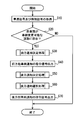
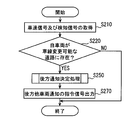
- FIG. 3 is a flowchart of the vehicle notification device according to the first embodiment.
- FIG. 4 is a flowchart showing the forward notification determination process of FIG.
- FIG. 5 is a flowchart showing the backward notification determination process of FIG.
- FIG. 6 is a flowchart showing the backward notification selection process of FIG.
- FIG. 7 is a schematic diagram illustrating an example of a notification state of the HUD device in the first embodiment.
- FIG. 8 is a schematic diagram illustrating another example of the notification state of the HUD device in the first embodiment.
- FIG. 9 is a schematic diagram illustrating an example of a notification state of the HUD device when the first stage notification in the first embodiment is selected.
- FIG. 10 is a schematic diagram illustrating an example of a notification state of the HUD device when the second stage notification in the first embodiment is selected.
- FIG. 11 is a schematic diagram showing the host vehicle, another vehicle, and a road according to the scene of Example 1 in the first embodiment.
- FIG. 12 is a schematic diagram showing the host vehicle, another vehicle, and a road according to the scene of Example 2 in the first embodiment.
- FIG. 13 is a schematic diagram showing the host vehicle, another vehicle, and a road according to the scene of Example 3 in the first embodiment.
- FIG. 14 is a schematic diagram showing the host vehicle, another vehicle, and a road according to the scene of Example 4 in the first embodiment.
- FIG. 15 is a schematic diagram showing the host vehicle, another vehicle, and a road according to the scene of Example 5 in the first embodiment.
- FIG. 16 is a schematic diagram showing the host vehicle, another vehicle, and a road according to the scene of Example 6 in the first embodiment.
- FIG. 17 is a flowchart of the vehicle notification device according to the second embodiment.
- FIG. 18 is a flowchart showing the backward notification determination process of FIG.
- a vehicle notification device 100 according to the first embodiment of the present disclosure shown in FIG. 1 is mounted on a host vehicle 1 that is an automobile.
- the vehicle notification device 100 includes an other vehicle detection sensor 2, a host vehicle speed sensor 3, an operation unit 4, a head-up display device 5 (hereinafter referred to as a HUD device), a vibration device 6 in a driver's seat 8, a speaker 7, and the like. And can be communicated by in-vehicle LAN.
- the vehicle notification device 100 is a command signal for notification regarding other vehicles to the HUD device 5, the vibration device 6, and the speaker 7 based on inputs from the other vehicle detection sensor 2, the host vehicle speed sensor 3, and the operation unit 4. Can be output.
- the notification regarding another vehicle is performed with respect to the passenger
- the passengers perceive these notifications by visual, tactile, and auditory senses, the passengers can recognize notifications regarding other vehicles.
- the own vehicle speed sensor 3 is a sensor that detects the vehicle speed Vo (hereinafter, the own vehicle speed) of the own vehicle 1. Specifically, the host vehicle speed sensor 3 detects the rotation speed of the axle of the host vehicle 1 and outputs a vehicle speed signal corresponding to the rotation speed to the vehicle notification device 100.
- the other vehicle detection sensor 2 is a sensor that detects other vehicles existing around the host vehicle 1.
- the other vehicle detection sensor 2 is mainly composed of a plurality of sensor elements such as a camera 2a and a millimeter wave radar 2b, for example, and a detection signal which is a detection result of the sensor elements 2a and 2b is used for the vehicle.
- the information is output to the notification device 100.
- the operation unit 4 is a part that is operated by the driver, and in particular in the present embodiment, corresponds to a direction indicating switch that turns on the winker 1f that performs a right / left turn signal (see also FIG. 16). When operated by a driver, the operation unit 4 outputs an operation signal to the vehicle notification device 100.
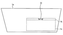
- the HUD device 5 is a vehicle display device that projects an image onto a projection member 1a such as a windshield to display a virtual image so that the image is visible in the visual recognition area 8a.
- the visual recognition area 8a is an area in which the image 30 as a virtual image can be visually recognized.
- the visual recognition area 8a is set in consideration of an eyelip that is a space area where a driver's eyepoint seated in the driver's seat 8 among the passengers can exist.
- the viewing area 8a as described above, the driver of the occupant can visually recognize the image 30 as a virtual image, and the assistant seated in the passenger seat 9 of the occupant cannot visually recognize the image 30 as a virtual image. In this manner, the HUD device 5 can display a virtual image of the image 30 to notify the driver about other vehicles.
- the vibration device 6 of the driver's seat 8 is provided at two places on the left and right inside the backrest of the driver's seat 8, and can individually notify the driver about other vehicles by vibrating individually.
- Speaker 7 is a device that outputs sound, and can notify each passenger about other vehicles.
- the vehicle notification device 100 is an electronic control device configured mainly with a control circuit 10 including a CPU 10 a and a memory 10 b.
- the CPU 10a can execute various processes by executing a computer program stored in the memory 10b.
- the memory 10b stores image data used for the HUD device 5 in addition to the computer program described above. Note that there may be a plurality of CPUs 10a and memories 10b.
- FIGS. 6 flowcharts executed by the execution of the computer program by the control circuit 10 of the vehicle notification device 100 according to the first embodiment in cooperation with the HUD device 5, the vibration device 6, the speaker 7, and the like are shown in FIGS. 6 will be described in detail.
- the process based on the flowchart shown in FIG. 3 is implemented for every set period, for example.
- each command signal when it is determined in step S30 or S50 that there is a notification regarding another vehicle is specifically defined as a notification signal.
- step S10 a vehicle speed signal and a detection signal are acquired. After the process of step S10, the process proceeds to step S20.
- step S20 it is determined whether or not the host vehicle 1 is present on a road where lane change is possible.
- the host vehicle speed Vo is calculated from the vehicle speed signal from the host vehicle speed sensor 3, and when the host vehicle speed Vo is higher than the set host vehicle speed Vos, it is determined that the vehicle exists on a road where the lane can be changed. That is, if the host vehicle 1 is traveling at a high speed, it is estimated that the host vehicle 1 exists on the highway, and if the host vehicle 1 is a highway, there is a high possibility that the host vehicle 1 has a plurality of lanes. It is presumed to exist on a road that can be changed. If it is determined in step S20 that the vehicle is on a road where lane change is possible, the process proceeds to step S30. If a negative determination is made in step S20, a series of processing ends.
- step S30 a forward notification determination process is performed for notifications related to other vehicles ahead. Specifically, the presence / absence of the notification signal is determined based on the distance Lp between the host vehicle 1 and the other vehicle and the relative speed Vrp of the other vehicle with respect to the host vehicle 1 with respect to the other vehicle ahead. After the process of step S30, the process proceeds to step S40.
- step S40 a command signal for notifying the other vehicle ahead is output to the HUD device 5. For example, when it is determined in step S30 that there is a notification signal, a notification signal as a command signal is output. After the process of step S40, the process proceeds to step S50.
- step S50 a rear notification determination process is performed for notification regarding other vehicles behind. Specifically, the presence or absence of a notification signal is determined based on the distance Lf between the host vehicle 1 and the other vehicle and the relative speed Vrf of the other vehicle with respect to the host vehicle 1 with respect to the other vehicle behind. After the process of step S50, the process proceeds to step S60.
- step S60 a rear notification selection process for a notification regarding other vehicles behind is performed. Specifically, based on the operation of the operation unit 4, the distance Lp between the host vehicle 1 and the other vehicle, and the relative speed Vrp of the other vehicle with respect to the host vehicle 1, a notification method and contents regarding the other vehicle behind are described. select. After the process of step S60, the process proceeds to step S70.
- step S70 a notification command signal regarding the other vehicle behind is output to the HUD device 5, the vibration device 6, and the speaker 7. For example, if it is determined in step S50 that there is a notification signal, a notification signal as a command signal is output. A series of processing is complete
- the distances Lp and Lf between the host vehicle 1 and the other vehicle used in steps S30 and S50 are calculated based on the detection signal from the other vehicle detection sensor 2 acquired in step S10.
- the distances Lp and Lf between the host vehicle 1 and the other vehicle can be obtained by analyzing the received wave of the millimeter wave radar 2b constituting the other vehicle detection sensor 2, or analyzing the captured image of the camera 2a, or a combination thereof.
- the relative speeds Vrp and Vrf of the other vehicle used in steps S30 and S50 with respect to the host vehicle 1 are also calculated based on the detection signal from the other vehicle detection sensor 2 acquired in step S10.
- the amount of change in the distances Lp and Lf obtained at each detection time can be set as the relative speeds Vrp and Vrf of the other vehicle with respect to the host vehicle 1.
- the distances Lp and Lf and the relative speeds Vrp and Vrf are corrected using the host vehicle speed. .
- the command signal in step S40 or S70 is a signal corresponding to the determination (and selection) in steps S30 or S50 and S60, respectively.
- the command signal is input to each of the devices 5, 6, and 7, the notification state of each device is updated.
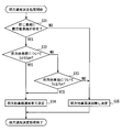
- step S30 the forward notification determination process in step S30 performed by the vehicle notification device 100 will be described in more detail using the flowchart shown as a subroutine in FIG.
- step S31 it is determined whether there is another vehicle ahead in the same lane as the own vehicle 1. If an affirmation judging is made at Step S31, it will move to Step S32. If a negative determination is made in step S31, the process proceeds to step S35.
- step S32 it is determined whether or not the distance Lp is equal to or less than the set distance Lps for other vehicles ahead. If an affirmation judging is made at Step S32, it will move to Step S34. If a negative determination is made in step S32, the process proceeds to step S33.
- step S33 it is determined whether or not the margin time Tp is equal to or less than the set time Tps for other vehicles ahead. If an affirmation judging is made at Step S33, it will move to Step S34. If a negative judging is made at Step S33, it will move to Step S35.
- step S34 it is determined that there is a notification signal for notification regarding other vehicles ahead.
- the forward notification determination process is terminated by step S34.
- step S35 it is determined that there is no notification signal regarding the other vehicle ahead.
- the forward notification determination process is terminated by step S35.
- the HUD device 5 to which a command signal related to the other vehicle ahead is input as a result of step S40 through step S34 or S35 will be briefly described.
- the notification signal is input when it is determined that there is a notification signal
- the HUD device 5 updates the notification state
- the other vehicle in front is the own vehicle 1 as a notification regarding the other vehicle in front.
- a forward notification image 31 indicating that the vehicle is approaching is displayed as a virtual image at the display location 1b.
- the HUD device 5 notifies the driver among the occupants.
- the HUD device 5 updates the notification state and stops the virtual image display of the forward notification image 31 by a command signal when it is determined that there is no notification.
- step S50 the rear notification determination process in step S50 performed by the vehicle notification device 100 will be described in more detail with reference to the flowchart shown in FIG.
- step S51 it is determined whether there is another vehicle behind. If an affirmation judging is made at Step S51, it will move to Step S52. If a negative judging is made at Step S51, it will move to Step S57.
- step S52 it is determined whether there is another vehicle behind in the same lane as the own vehicle 1. If an affirmation judging is made at Step S52, it will move to Step S54. If a negative determination is made in step S52, the process proceeds to step S53.
- step S53 it is determined in the forward notification determination process in step S30 whether or not it is determined that there is a notification signal related to the other vehicle ahead. If an affirmation judging is made at Step S53, it will move to Step S54. If a negative determination is made in step S53, the process proceeds to step S57.
- step S54 it is determined whether or not the distance Lf is less than or equal to the set distance Lfs for other vehicles behind. If an affirmation judging is made at Step S54, it will move to Step S56. If a negative determination is made in step S54, the process proceeds to step S55.
- step S55 it is determined whether or not the margin time Tf is less than or equal to the set time Tfs for other vehicles behind.
- the margin time Tf is calculated in the same manner as Tp. If an affirmation judging is made at Step S55, it will move to Step S56. If a negative judging is made at Step S55, it will move to Step S57.
- step S56 it is determined that there is a notification signal for notification regarding other vehicles behind.
- the backward notification determination process is terminated by step S56.
- step S57 it is determined that there is no notification signal for notification regarding other vehicles behind.
- the backward notification determination process is terminated in step S57.
- step S60 the rear notification selection processing in step S60 performed by the vehicle notification device 100 will be described in more detail using the flowchart shown as a subroutine in FIG.
- step S61 it is determined whether or not it is determined that there is a notification signal related to the other vehicle behind in the rear notification determination process in step S50. If an affirmation judging is made at Step S61, it will move to Step S62. If a negative determination is made in step S61, the process proceeds to step S67.
- step S62 it is determined whether or not the margin time Tf is equal to or less than the set selection time Tfe for the other vehicle behind.
- the setting selection time Tfe is shorter than the setting time Tfs. If an affirmation judging is made at Step S62, it will move to Step S63. If a negative determination is made in step S62, the process proceeds to step S66.
- step S63 it is determined whether or not the operation unit 4 is operated. If an affirmation judging is made at Step S63, it will move to Step S64. If a negative determination is made in step S63, the process proceeds to step S65.
- step S64 the third stage notification is selected.
- the backward notification selection process is terminated through step S64.
- step S65 the second stage notification is selected.
- the backward notification selection process is terminated by step S65.
- step S66 the first stage notification is selected.
- the backward notification selection process is terminated by step S66.
- step S67 no notification is selected.
- the backward notification selection process is terminated in step S67.
- the third stage notification is the most urgent.
- the notification at each stage will be described in detail below.
- step S57 it is determined in step S57 that there is no notification signal related to the other vehicle behind, and each device 5, 6, 7 by the command signal when no notification is selected in step S67 updates the notification state. , Stop notifications.
- step S56 each of the devices 5, 6, and 7 based on the notification signal when it is determined in step S56 that there is a notification signal regarding the other vehicle behind and the first stage notification is selected in step S66 will be described.
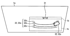
- the HUD device 5 displays a rear notification image 32 indicating that the other vehicle behind is approaching the host vehicle 1. More specifically, the rear notification image 32 has a display location 1c below the host vehicle 1 rather than the display location 1b of the front notification image 31.
- the rear notification image 32 is mainly composed of a reference image 32a and a rear other vehicle image 32c.
- the reference image 32 a in this embodiment three linear line images 32 b extending substantially along the lateral direction of the host vehicle 1 are arranged in parallel in the vertical direction of the host vehicle 1.
- the rear other vehicle image 32c in the present embodiment is an image simulating another vehicle, and the relative display position with respect to the reference image 32a is determined based on the detection signal from the other vehicle detection sensor 2.
- the rear other vehicle image 32c is displayed at the center of the reference image 32a as shown in FIG. Further, the relative display position of the rear other vehicle image 32c in the vertical direction with respect to the reference image 32a is determined based on the margin time Tf for the rear other vehicle. In the example of FIG. 9, the upper end 32d of the rear other vehicle image 32c is displayed so as to overlap between the three line images 32b. In this way, the HUD device 5 notifies the driver among the occupants.
- the vibration device 6 stops the vibration as a notification.
- the speaker 7 also stops outputting sound as a notification.
- step S56 each of the devices 5, 6, and 7 based on the notification signal when it is determined in step S56 that the notification signal for the other vehicle behind is determined to be present and the second stage notification is selected in step S65 will be described.
- the HUD device 5 displays a rear notification image 32 indicating that the other vehicle behind is approaching the host vehicle 1.
- the rear other vehicle image 32c is above the three line images 32b, that is, more forward notification images. 31 is displayed with an upper end 32d arranged on the display portion 1b side.
- the rear other vehicle image 32 c is displayed on the relatively right side of the reference image 32 a as a case where the other vehicle behind is present in the lane on the right side of the host vehicle 1.
- the vibration device 6 stops the vibration as a notification in a stopped state, similarly to the first stage notification.
- the speaker 7 also stops the output of sound as a notification in the same manner as the first stage or notification.
- step S56 each of the devices 5, 6, and 7 based on the notification signal when it is determined in step S56 that the notification signal regarding the other vehicle behind is present and the third-stage notification is selected in step S64 will be described.
- the HUD device 5 displays the rear notification image 32 similar to the second stage notification shown in FIG. 10 in a virtual image, but changes the hue of the rear notification image 32 to indicate an alarm.
- the white color in the first stage notification and the second stage notification is changed to red.
- the vibration device 6 notifies the driver of the occupant by vibrating.
- the speaker 7 also notifies the occupant by outputting sound.
- a passenger other than the driver is also notified.
- Example 1 As shown in FIG. 11, the host vehicle 1 travels in the overtaking lane 40b, and the other vehicle 42a behind travels in the overtaking lane 40b.
- the distance between the host vehicle 1 and the other vehicle 42a is L1> Lfs, and the relative speed of the other vehicle 42a with respect to the host vehicle 1 is Vr1.
- the margin time T1 L1 / Vr1, and Tfe ⁇ T1 ⁇ Tfs.
- step S50 an affirmative determination is made in steps S51 and S52, and a negative determination is made in step S54. Since an affirmative determination is made in step S55, it is determined in step S56 that there is a notification signal related to the other vehicle 42a behind.
- step S60 In the backward notification selection process in step S60, an affirmative determination is made in step S61, but a negative determination is made in step S62, so the first stage notification is selected in step S66.
- the HUD device 5 displays a rear notification image 32 as shown in FIG.
- the distance L1 is larger than the set distance Lfs, but the margin time T1 is smaller than the set time Tfs, so that the risk that the own vehicle 1 collides with the other vehicle 42a is high. A notice was made to encourage avoidance.
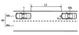
- Example 2 As shown in FIG. 12, the host vehicle 1 travels in the overtaking lane 40b, and the other vehicle 42b behind travels in the overtaking lane 40b.
- the distance between the host vehicle 1 and the other vehicle 42b is L2> Lfs, and the relative speed of the other vehicle 42b with respect to the host vehicle 1 is Vr2.
- the margin time T2 L2 / Vr2.
- L2 L1, Vr2 ⁇ Vr1, and T2> Tfs.
- step S50 an affirmative determination is made in steps S51 and S52, and a negative determination is made in steps S54 and S55. Therefore, in step S57, a notification signal for notification regarding the rear other vehicle 42b is issued. Determined to be none.
- the distance L2 is the same as that of the first embodiment, but since the margin time T2 is larger than the set time Tfs, the risk that the own vehicle 1 collides with the other vehicle 42b is small. No notification was made to reduce annoyance.
- Example 3 As shown in FIG. 13, the host vehicle 1 travels in the overtaking lane 40b, and the other vehicle 42c behind travels in the overtaking lane 40b.
- the distance between the host vehicle 1 and the other vehicle 42c is L3 ⁇ Lfs, and the relative speed of the other vehicle 42c with respect to the host vehicle 1 is Vr3.
- step S50 since an affirmative determination is made in steps S51, S52, and S54, it is determined in step S56 that there is a notification signal regarding the other vehicle 42c in the rear.
- step S60 In the backward notification selection process in step S60, an affirmative determination is made in step S61, but a negative determination is made in step S62, so the first stage notification is selected in step S66.
- the HUD device 5 displays a rear notification image 32 as shown in FIG.
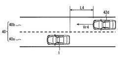
- Example 4 As shown in FIG. 14, the host vehicle 1 travels in the travel lane 40 a, and the other vehicle 42 d behind travels in the overtaking lane 40 b.
- the distance between the host vehicle 1 and the other vehicle 42d is L4> Lfs, and the relative speed of the other vehicle 42d with respect to the host vehicle 1 is Vr4.
- the margin time T4 L4 / Vr4, and T4 ⁇ Tfe.
- step S30 since no other vehicle ahead of the host vehicle 1 exists in the same lane, a negative determination is made in step S31, and a notification signal for notification regarding the other vehicle ahead is issued in step S35. Determined to be none.
- step S50 In the backward notification determination process in step S50, an affirmative determination is made in step S51, but a negative determination is made in step S52. Since a negative determination is made in S53 as a result that no other vehicle ahead of the host vehicle 1 is present in the same lane, it is determined in step S57 that there is no notification signal regarding the other vehicle 42d behind. .
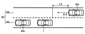
- Example 5 As shown in FIG. 15, the host vehicle 1 travels in the travel lane 40 a, and the other vehicle 42 e behind travels in the overtaking lane 40 b.
- the distance between the host vehicle 1 and the other vehicle 42e is L4, and the relative speed of the other vehicle 42e with respect to the host vehicle 1 is Vr4.
- the margin time T4 L4 / Vr4.
- the other vehicle 44e ahead travels on the same traveling lane 40a as the host vehicle 1, and it is determined in the forward notification determination process in step S30 that there is a notification signal regarding the other vehicle 44e ahead. It was.
- step S50 an affirmative determination is made in step S51, a negative determination is made in step S52, an affirmative determination is made in step S53, and a negative determination is further made in step S54. Is done. Since an affirmative determination is made in step S55, it is determined in step S56 that there is a notification signal related to the other vehicle 42e behind.
- step S60 an affirmative determination is made in step S61 and an affirmative determination is made in step S62, but an affirmative determination is made in step S63. A notification is selected.
- the HUD device 5 displays a virtual image 30 as shown in FIG.
- the host vehicle 1 and the other vehicle 42e are traveling on different lanes 40a and 40b.
- the host vehicle 1 moves to the same lane 40b as the other vehicle 42e.
- the possibility of changing lanes is increasing. For this reason, a notification was made to encourage avoidance.
- Example 6 As shown in FIG. 16, the host vehicle 1 travels in the travel lane 40a, and the other vehicle 42f behind travels in the overtaking lane 40b.
- the distance between the host vehicle 1 and the other vehicle 42f is L4, and the relative speed of the other vehicle 42f with respect to the host vehicle 1 is Vr4.
- the margin time T4 L4 / Vr4.
- the other vehicle 44f ahead travels on the same traveling lane 40a as the host vehicle 1, and it is determined in the forward notification determination process in step S30 that there is a notification signal regarding the other vehicle 44f ahead. It was done.
- the right turn signal 1f is lit.
- step S50 it is determined that there is a notification signal for notification regarding the other vehicle 42f in the rear.
- step S60 since an affirmative determination is made in steps S61 to S63, the third stage notification is selected in step S64.
- the HUD device 5 displays a virtual image of the red image 30 as shown in FIG. 10, and the vibration device 6 vibrates to notify the driver of the occupant.
- the speaker 7 also notifies the occupant by outputting sound.
- the HUD device 5, the vibration device 6, and the speaker 7 constitute a notification unit
- the control circuit 10 that executes Step S20 constitutes a determination unit
- the forward notification determination process in Step S30, and S50 constitutes a notification determination unit
- the control circuit 10 that executes the backward notification selection process in step S60 constitutes a notification selection unit.
- the presence / absence of a notification signal regarding the other vehicle is determined based on the distances Lp and Lf between the host vehicle and the other vehicle, It is determined based on relative speeds Vrp and Vrf with respect to the host vehicle 1. According to this, in the determination of the presence / absence of the notification, whether or not the collision can be avoided by changing the lane is taken into account, and even when the distances Lp and Lf are the same, the relative speeds Vrp and Vrf are determined in consideration of the collision risk. Because it is taken into account, notification can be made appropriately according to the situation. Therefore, it is possible to provide the vehicle notification device 100 that promotes avoiding a collision with another vehicle while reducing the troublesomeness of the notification to be made to the occupant of the host vehicle 1.
- the notification regarding the other vehicle is calculated based on the distances Lp and Lf and the relative speeds Vrp and Vrf. If the margin times Tp and Tf are less than or equal to the set times Tps and Tfs, it is determined that there is. According to this, since the notification is urged based on the surplus times Tp and Tf for the driver to avoid the collision, the troublesomeness of the notification is reduced and the notification can be made appropriately.
- the rear vehicle that is, the other vehicle behind
- the risk of the own vehicle 1 coming into contact with the rear vehicle increases.
- the risk is not so high unless the vehicle 1 changes lanes.
- a forward vehicle that is, another vehicle ahead
- the possibility that the own vehicle 1 changes lanes is lower than when there is no forward vehicle.
- the first embodiment when there is no forward vehicle in the same lane as the own vehicle 1, it is considered that the possibility that the own vehicle 1 will change the lane is low, and the rear vehicle is different from the own vehicle 1 Even if it exists, the above notification is not made regardless of the distance and relative speed with the rear vehicle. For this reason, it is possible to avoid notifying even when the risk is not high, so that the troublesomeness of the notification can be reduced.
- the notification method and contents are selected based on the operation of the operation unit 4 that the host vehicle 1 has and is operated by a passenger, the distance Lf, and the relative speed Vrf. According to this, the notification method and content take into account the risk of collision with other vehicles.
- the notification method and content corresponding to this change can be made, so that notification can be appropriately made according to the situation.
- the second embodiment of the present disclosure is a modification of the first embodiment.
- the second embodiment will be described with a focus on differences from the first embodiment.
- Step S220 Since the processing of steps S210 and S220 is the same as S10 and S20 of the first embodiment, description thereof is omitted. If an affirmation judging is made at Step S220, it will move to Step S250.
- step S250 a rear notification determination process is performed for notification regarding other vehicles behind. More specifically, the presence / absence of a notification signal related to the other vehicle is determined based on the distance Lf between the own vehicle 1 and the other vehicle and the relative speed Vrf of the other vehicle to the own vehicle 1 with respect to the other vehicle behind. decide. After step S250, the process proceeds to step S270.
- step S270 as in S70 of the first embodiment, a notification command signal related to the other vehicle behind is output to the HUD device 5, the vibration device 6, and the speaker 7. For example, if it is determined in step S250 that there is a notification signal, a notification signal as a command signal is output. A series of processing is complete
- step S250 the backward notification determination process in step S250 will be described in more detail using a flowchart shown as a subroutine in FIG.
- step S251 it is determined whether there is another vehicle behind. If an affirmation judging is made at Step S251, it will move to Step S252. If a negative determination is made in step S251, the process proceeds to step S255.
- step S252 it is determined whether or not the distance Lf is less than or equal to the set distance Lfs for other vehicles behind. If an affirmation judging is made at Step S252, it will move to Step S254. If a negative determination is made in step S252, the process proceeds to step S253.
- step S253 it is determined whether or not the relative speed Vrf is equal to or higher than the set speed Vrfs for other vehicles behind. If an affirmation judging is made at Step S253, it will move to Step S254. If a negative determination is made in step S253, the process proceeds to step S255.
- step S254 it is determined that there is a notification signal for notification regarding other vehicles behind.
- the backward notification determination process is terminated by step S254.
- step S255 it is determined that there is no notification signal for notification regarding other vehicles behind.
- the backward notification determination process is terminated by step S255.
- the distance Lf between the host vehicle 1 and the other vehicle, and the host vehicle 1 of the other vehicle is determined based on the relative speed Vrf with respect to. Therefore, it is possible to achieve the operational effects according to the first embodiment.
- the relative speed Vrf is equal to or higher than the set speed Vrfs, it is determined that there is a notification regarding another vehicle. If the relative speed Vrf is large, even if the distance Lf is large, the other vehicle will eventually approach and the risk of collision will increase, so in this case it is determined that there is a notification.
- the HUD device 5, the vibration device 6, and the speaker 7 constitute a notification unit
- the control circuit 10 that executes Step S220 constitutes a determination unit, and executes the backward notification determination process in Step S250.
- the vehicle notification device 100 outputs a notification signal to devices other than the HUD device 5, the vibration device 6, and the speaker 7.
- a combination meter, a car navigation system, or an electronic mirror that receives a notification signal may display a real image as a notification to the occupant.
- an LED to which a notification signal is input may be turned on as a notification to the occupant.
- the steering wheel to which the notification signal is input may vibrate as a notification to the driver among the occupants.
- distances Lp and Lf between the host vehicle 1 and other vehicles and relative speeds Vrp and Vrf of the other vehicle with respect to the host vehicle 1 are vehicle-to-vehicle communication, road-to-vehicle communication, etc. You may make it acquire by this communication.
- whether or not the host vehicle 1 is present on a lane-changeable road may be determined using GPS or the like.
- the distances Lp and Lf between the host vehicle 1 and other vehicles when it is determined that the host vehicle 1 is present on a road where lane change is possible, the distances Lp and Lf between the host vehicle 1 and other vehicles, Various means can be employed if the presence or absence of the notification signal is determined based on the relative speeds Vp and Vf of the other vehicle with respect to the host vehicle 1.
- the set distances Lps and Lfs and the set times Tps and Tfs may be varied according to the positional relationship with other vehicles, the road alignment, and the like.
- the presence or absence of a notification signal may be determined based on a return value of a function (for example, a special parameter) based on the distances Lp and Lf and the relative speeds Vrp and Vrf.
- a function for example, a special parameter
- the presence / absence of a notification signal may be determined based on the distances Lp and Lf, the relative speeds Vrp and Vrf, and the acceleration.
- each part is expressed as, for example, S100. Furthermore, each part can be divided into a plurality of sub-parts, while the plurality of parts can be combined into one part. Furthermore, each part configured in this manner can be referred to as a circuit, a device, a module, and a means.
- Each of the above-mentioned plurality of parts or a combination thereof is not only (i) a software part combined with a hardware unit (for example, a computer), but also (ii) hardware (for example, an integrated circuit, As a part of the (wiring logic circuit), it can be realized with or without including the functions of related devices.
- the hardware unit can be configured inside a microcomputer.
Landscapes
- Engineering & Computer Science (AREA)
- Mechanical Engineering (AREA)
- Transportation (AREA)
- Chemical & Material Sciences (AREA)
- Combustion & Propulsion (AREA)
- Physics & Mathematics (AREA)
- General Physics & Mathematics (AREA)
- Human Computer Interaction (AREA)
- Aviation & Aerospace Engineering (AREA)
- Traffic Control Systems (AREA)
Abstract
乗員に通知を行なう通知部(5,6,7)を有する自車両(1)に搭載され、通知部に対して他車両に関する通知の通知信号を出力する車両用通知装置は、自車両が車線変更可能な道路に存在しているか否かを判定する判定部(S20,S220)と、判定部により自車両が車線変更可能な道路に存在していると判定された場合に、自車両と他車両との距離(Lp,Lf)と、他車両の自車両に対する相対速度(Vrp,Vrf)とに基づいて、通知信号を通知部に出力するかしないかを決定する通知決定部(S30,S50,S250)と、を備える。
Description
本出願は、2014年8月21日に出願された日本出願番号2014-168796号に基づくもので、ここにその記載内容を援用する。
本開示は、乗員に通知を行なう通知部を有する自車両に搭載され、当該通知を通知部に対して促す車両用通知装置に関する。
従来、乗員に通知を行なう通知部を有する自車両に搭載され、当該通知を通知部に対して促す車両用通知装置が知られている。特許文献1に開示の車両用通知装置を含む安全走行支援システムでは、警告を行なうか否かの判定基準としての警告範囲に他車両があるか否かを判定し、他車両がある場合、画像をヘッドアップディスプレイに表示させ、かつ、スピーカを用いた音声による警告を行なう。すなわち、自車両と他車両の距離に基づいて警告が行われる。
自車両と他車両との距離や他車両の自車両に対する相対速度と、自車両が他車両と衝突するリスクとの関連性について考えてみたい。例えば、同じ距離であっても、相対速度が小さければリスクが低く、その一方で、相対速度が大きければ、いずれリスクが高くなる可能性が高いので、状況に合わせて適切に通知を行なった方がよいと思われる。しかしながら、特許文献1の判定では距離に応じて一律に警告してしまうので、自車両の乗員に対して行う通知の煩わしさを低減しつつ、他車両との衝突を回避するように促すことが十分できなかった。
本開示は、上記点に鑑みてなされたものであり、その目的は、自車両の乗員に対して行う通知の煩わしさを低減しつつ、他車両との衝突を回避するように促す車両用通知装置を提供することにある。
本開示の一態様による車両用通知装置は、乗員に通知を行なう通知部を有する自車両に搭載され、通知部に対して他車両に関する通知の通知信号を出力する。車両用通知装置は、自車両が車線変更可能な道路に存在しているか否かを判定する判定部と、判定部により自車両が車線変更可能な道路に存在していると判定された場合に、自車両と他車両との距離と、他車両の自車両に対する相対速度と、に基づいて、通知信号を通知部に出力するかしないかを決定する通知決定部とを備える。
上記装置によると、自車両が車線変更可能な道路に存在している場合、他車両に関する通知の通知信号の有無は、自車両と他車両との距離と、他車両の自車両に対する相対速度とに基づいて決定される。これによれば、通知の有無の決定において、車線変更で衝突を回避可能であるかが考慮され、なおかつ、同じ距離の場合でも、衝突するリスクを考慮するにあたり相対速度が加味されるので、状況に合わせて適切に通知をすることができる。したがって、自車両の乗員に対して行う通知の煩わしさを低減しつつ、他車両との衝突を回避するように促す車両用通知装置を提供することができる。
本開示についての上記目的およびその他の目的、特徴や利点は、添付の図面を参照しながら下記の詳細な記述により、より明確になる。その図面は、
図1は、第1実施形態の自車両における車両用通知装置を説明するためのブロック図であり、
図2は、第1実施形態における自車両におけるHUD装置及び振動装置を説明するための模式図であり、
図3は、第1実施形態における車両用通知装置によるフローチャートであり、
図4は、図3の前方通知決定処理を示すフローチャートであり、
図5は、図3の後方通知決定処理を示すフローチャートであり、
図6は、図3の後方通知選択処理を示すフローチャートであり、
図7は、第1実施形態におけるHUD装置の通知状態の一例を示す模式図であり、
図8は、第1実施形態におけるHUD装置の通知状態の他の一例を示す模式図であり、
図9は、第1実施形態における第1段階通知が選択された場合のHUD装置の通知状態の一例を示す模式図であり、
図10は、第1実施形態における第2段階通知が選択された場合のHUD装置の通知状態の一例を示す模式図であり、
図11は、第1実施形態における実施例1の場面による自車両、他車両、及び道路を示す模式図であり、
図12は、第1実施形態における実施例2の場面による自車両、他車両、及び道路を示す模式図であり、
図13は、第1実施形態における実施例3の場面による自車両、他車両、及び道路を示す模式図であり、
図14は、第1実施形態における実施例4の場面による自車両、他車両、及び道路を示す模式図であり、
図15は、第1実施形態における実施例5の場面による自車両、他車両、及び道路を示す模式図であり、
図16は、第1実施形態における実施例6の場面による自車両、他車両、及び道路を示す模式図であり、
図17は、第2実施形態における車両用通知装置によるフローチャートであり、
図18は、図17の後方通知決定処理を示すフローチャートである。
以下、本開示の複数の実施形態を図面に基づいて説明する。なお、各実施形態において対応する構成要素には同一の符号を付すことにより、重複する説明を省略する場合がある。各実施形態において構成の一部分のみを説明している場合、当該構成の他の部分については、先行して説明した他の実施形態の構成を適用することができる。また、各実施形態の説明において明示している構成の組み合わせばかりではなく、特に組み合わせに支障が生じなければ、明示していなくても複数の実施形態の構成同士を部分的に組み合せることができる。
(第1実施形態)
図1に示す本開示の第1実施形態による車両用通知装置100は、自動車である自車両1に搭載されている。車両用通知装置100は、自車両1が有する他車両検知センサ2、自車速センサ3、操作部4、ヘッドアップディスプレイ装置5(以下、HUD装置)、運転席8の振動装置6、スピーカ7等と車内LANにより通信可能となっている。車両用通知装置100は、他車両検知センサ2、自車速センサ3、及び操作部4からの入力に基づいて、HUD装置5、振動装置6、及びスピーカ7に対して他車両に関する通知の指令信号を出力することが可能となっている。そして、通知をするように指令を受けたHUD装置5、振動装置6、及びスピーカ7により、他車両に関する通知が自車両1の乗員に対して行われる。これらの通知を、自車両1の乗員が視覚、触覚、及び聴覚によって知覚することで、当該乗員は、他車両に関する通知を認識することができる。
図1に示す本開示の第1実施形態による車両用通知装置100は、自動車である自車両1に搭載されている。車両用通知装置100は、自車両1が有する他車両検知センサ2、自車速センサ3、操作部4、ヘッドアップディスプレイ装置5(以下、HUD装置)、運転席8の振動装置6、スピーカ7等と車内LANにより通信可能となっている。車両用通知装置100は、他車両検知センサ2、自車速センサ3、及び操作部4からの入力に基づいて、HUD装置5、振動装置6、及びスピーカ7に対して他車両に関する通知の指令信号を出力することが可能となっている。そして、通知をするように指令を受けたHUD装置5、振動装置6、及びスピーカ7により、他車両に関する通知が自車両1の乗員に対して行われる。これらの通知を、自車両1の乗員が視覚、触覚、及び聴覚によって知覚することで、当該乗員は、他車両に関する通知を認識することができる。
自車速センサ3は、自車両1の車速Vo(以下、自車速)検出するセンサである。具体的に自車速センサ3は、自車両1の車軸の回転数を検出し、回転数に応じた車速信号を車両用通知装置100に出力するようになっている。
他車両検知センサ2は、自車両1の周辺に存在する他車両を検知するセンサである。具体的に、他車両検知センサ2は、例えばカメラ2a、及びミリ波レーダ2b等の複数のセンサ素子を主体として構成されており、これらセンサ素子2a,2bの検知結果である検知信号を車両用通知装置100に出力するようになっている。
操作部4は、運転手が運転操作する部品であり、特に本実施形態では右左折の合図を行なうウインカー1fを点灯させる方向指示スイッチが該当する(図16も参照)。操作部4は、運転手によって操作されると、操作信号を車両用通知装置100に出力するようになっている。
HUD装置5は、図2に示すように、例えばウインドシールド等の投影部材1aに画像を投影することにより、当該画像を視認領域8aにおいて視認可能に虚像表示する車両用表示装置である。ここで、視認領域8aとは、虚像としての画像30が視認可能となる領域である。本実施形態では、乗員のうち、運転席8に着席した運転手のアイポイントが存在可能な空間領域であるアイリプスを考慮して、視認領域8aが設定されている。このような視認領域8aの設定により、乗員のうち運転手は虚像としての画像30を視認可能となり、乗員のうち助手席9に着席した助手は虚像としての画像30を視認できない。このようにして、HUD装置5は、画像30を虚像表示することで、運転手に他車両に関する通知を行なうことが可能となっている。
運転席8の振動装置6は、運転席8の背もたれ内部の左右2箇所に設けられ、それぞれ個別に振動することにより、運転手に他車両に関する通知を行なうことが可能となっている。
スピーカ7は、音声を出力する装置であり、各乗員に他車両に関する通知を行なうことが可能となっている。
車両用通知装置100は、図1に示すように、CPU10a及びメモリ10b等からなる制御回路10を主体として構成されている電子制御装置である。CPU10aは、メモリ10bに記憶されているコンピュータプログラムを実行することで、各種処理を実施可能となっている。メモリ10bは、上述のコンピュータプログラムに加えて、HUD装置5に用いる画像データ等も記憶している。なお、CPU10a及びメモリ10bは、複数あってもよい。
次に、第1実施形態における車両用通知装置100の制御回路10が、HUD装置5、振動装置6、及びスピーカ7等と連携して、コンピュータプログラムの実行により実施されるフローチャートを、図3~6に基づいて詳細に説明する。図3に示すフローチャートに基づいた処理が例えば設定周期毎に実施される。なお、指令信号のうち、ステップS30又はS50にて他車両に関する通知が有りと決定された場合のそれぞれの指令信号を、特に通知信号と定義する。
まず、ステップS10では、車速信号及び検知信号を取得する。ステップS10の処理後、ステップS20に移る。
ステップS20では、自車両1が車線変更可能な道路に存在しているか否かを判定する。特に本実施形態では、自車速センサ3からの車速信号から自車速Voを算出し、当該自車速Voが設定自車速Vosよりも大きい場合、車線変更可能な道路に存在していると判定する。すなわち、自車両1が高速で走行していれば、高速道路に存在しているものと推定した上、高速道路であれば複数車線を有している可能性が高いとして、自車両1が車線変更可能な道路に存在しているものと推定するのである。ステップS20にて車線変更可能な道路に存在していると判定すると、ステップS30に移る。ステップS20にて否定判定を下すと、一連の処理を終了する。
ステップS30では、前方の他車両に関する通知についての前方通知決定処理を行なう。具体的には、前方の他車両に対して、自車両1と他車両との距離Lpと、他車両の自車両1に対する相対速度Vrpとに基づいて、通知信号の有無を決定する。ステップS30の処理後、ステップS40に移る。
ステップS40では、HUD装置5に対して前方の他車両に関する通知の指令信号を出力する。例えば、ステップS30にて通知信号が有りと決定された場合には、指令信号としての通知信号を出力する。ステップS40の処理後、ステップS50に移る。
ステップS50では、後方の他車両に関する通知についての後方通知決定処理を行なう。具体的には、後方の他車両に対して、自車両1と他車両との距離Lfと、他車両の自車両1に対する相対速度Vrfとに基づいて、通知信号の有無を決定する。ステップS50の処理後、ステップS60に移る。
ステップS60では、後方の他車両に関する通知についての後方通知選択処理を行なう。具体的には、操作部4の操作と、自車両1と他車両との距離Lpと、他車両の自車両1に対する相対速度Vrpとに基づいて、後方の他車両に関する通知の方法及び内容を選択する。ステップS60の処理後、ステップS70に移る。
ステップS70では、HUD装置5、振動装置6、及びスピーカ7に対して後方の他車両に関する通知の指令信号を出力する。例えば、ステップS50にて通知信号が有りと決定された場合には、指令信号としての通知信号を出力する。ステップS70を以って一連の処理を終了する。
本実施形態において、ステップS30及びS50にて用いられる自車両1と他車両との距離Lp,Lfは、ステップS10にて取得する他車両検知センサ2からの検知信号を主体に算出される。例えば、他車両検知センサ2を構成するミリ波レーダ2bの受信波の解析、若しくはカメラ2aの撮影画像の解析、又はこれらの複合により、自車両1と他車両との距離Lp,Lfが得られる。同様に、本実施形態において、ステップS30及びS50にて用いられる他車両の自車両1に対する相対速度Vrp,Vrfも、ステップS10にて取得する他車両検知センサ2からの検知信号を主体に算出される。例えば、検知時間毎に得られた上述の距離Lp,Lfの変化量を、他車両の自車両1に対する相対速度Vrp,Vrfとすることができる。ここで、自車速センサ3からの車速信号によって得られた自車速Voの変化量が大きいとされた場合には、当該自車速を用いて距離Lp,Lf及び相対速度Vrp,Vrfが補正される。
このように、ステップS40又はS70における指令信号は、それぞれステップS30又はS50及びS60の決定(及び選択)に応じた信号となる。指令信号が各装置5,6,7に入力されると、各装置の通知状態は更新されることとなる。
次に、車両用通知装置100が実施するステップS30の前方通知決定処理について、図4にサブルーチンとして示すフローチャートを用いて、さらに詳細に説明する。
まず、ステップS31では、自車両1と同じ車線に前方の他車両が存在するか否かを判定する。ステップS31にて肯定判定を下すと、ステップS32に移る。ステップS31にて否定判定を下すと、ステップS35に移る。
ステップS32では、前方の他車両について、距離Lpが設定距離Lps以下であるか否かを判定する。ステップS32にて肯定判定を下すと、ステップS34に移る。ステップS32にて否定判定を下すと、ステップS33に移る。
ステップS33では、前方の他車両について、余裕時間Tpが設定時間Tps以下であるか否かを判定する。ステップS33にて肯定判定を下すと、ステップS34に移る。ステップS33にて否定判定を下すと、ステップS35に移る。
ステップS34では、前方の他車両に関する通知の通知信号を有りと決定する。ステップS34を以って前方通知決定処理を終了する。
ステップS35では、前方の他車両に関する通知の通知信号を無しと決定する。ステップS35を以って前方通知決定処理を終了する。
上記ステップS33にて用いられる余裕時間Tpは、距離Lpと相対速度Vrpに基づいて算出される。具体的に余裕時間Tpは、現在の相対速度Vrpが維持されると仮定してあと何秒で自車両1と他車両が衝突することとなるかを表す指標であり、例えばTp=Lp/Vrpで示される。
またここで、ステップS34又はS35を経たステップS40の結果、前方の他車両に関する指令信号が入力されたHUD装置5について簡単に説明する。図7に示すように、通知信号が有りと決定された場合の通知信号の入力により、HUD装置5は、通知状態を更新し、前方の他車両に関する通知として、前方の他車両が自車両1に接近していることを示す前方通知画像31を表示箇所1bに虚像表示する。このようにしてHUD装置5は、乗員のうち運転手に通知を行なう。一方、図8に示すように、通知が無しと決定された場合の指令信号により、HUD装置5は、通知状態を更新し、前方通知画像31の虚像表示を停止する。
次に、車両用通知装置100が実施するステップS50の後方通知決定処理について、図5にサブルーチンとして示すフローチャートを用いて、さらに詳細に説明する。
まず、ステップS51では、後方の他車両が存在するか否かを判定する。ステップS51にて肯定判定を下すと、ステップS52に移る。ステップS51にて否定判定を下すと、ステップS57に移る。
ステップS52では、自車両1と同じ車線に後方の他車両が存在するか否かを判定する。ステップS52にて肯定判定を下すと、ステップS54に移る。ステップS52にて否定判定を下すと、ステップS53に移る。
ステップS53では、ステップS30の前方通知決定処理において、前方の他車両に関する通知の通知信号が有りと決定されたか否かを判定する。ステップS53にて肯定判定を下すと、ステップS54に移る。ステップS53にて否定判定を下すと、ステップS57に移る。
ステップS54では、後方の他車両について、距離Lfが設定距離Lfs以下であるか否かを判定する。ステップS54にて肯定判定を下すと、ステップS56に移る。ステップS54にて否定判定を下すと、ステップS55に移る。
ステップS55では、後方の他車両について、余裕時間Tfが設定時間Tfs以下であるか否かを判定する。なお、余裕時間TfもTpと同様に算出される。ステップS55にて肯定判定を下すと、ステップS56に移る。ステップS55にて否定判定を下すと、ステップS57に移る。
ステップS56では、後方の他車両に関する通知の通知信号を有りと決定する。ステップS56を以って後方通知決定処理を終了する。
ステップS57では、後方の他車両に関する通知の通知信号を無しと決定する。ステップS57を以って後方通知決定処理を終了する。
次に、車両用通知装置100が実施するステップS60の後方通知選択処理について、図6にサブルーチンとして示すフローチャートを用いて、さらに詳細に説明する。
まず、ステップS61では、ステップS50の後方通知決定処理において後方の他車両に関する通知の通知信号が有りと決定されたか否かを判定する。ステップS61にて肯定判定を下すと、ステップS62に移る。ステップS61にて否定判定を下すと、ステップS67に移る。
ステップS62では、後方の他車両について、余裕時間Tfが設定選択時間Tfe以下であるか否かを判定する。ここで、設定選択時間Tfeは設定時間Tfsよりも小さいものとする。ステップS62にて肯定判定を下すと、ステップS63に移る。ステップS62にて否定判定を下すと、ステップS66に移る。
ステップS63では、操作部4が操作されているか否かを判定する。ステップS63にて肯定判定を下すと、ステップS64に移る。ステップS63にて否定判定を下すと、ステップS65に移る。
ステップS64では、第3段階通知を選択する。ステップS64を以って後方通知選択処理を終了する。
ステップS65では、第2段階通知を選択する。ステップS65を以って後方通知選択処理を終了する。
ステップS66では、第1段階通知を選択する。ステップS66を以って後方通知選択処理を終了する。
ステップS67では、無通知を選択する。ステップS67を以って後方通知選択処理を終了する。
ここで、通知の段階は、第3段階通知が最も緊急性が高いものとなっている。各段階における通知について、以下に詳細に説明する。
まず、ステップS57にて後方の他車両に関する通知の通知信号を無しと決定され、ステップS67にて無通知が選択された場合の指令信号による各装置5,6,7は、通知状態を更新し、通知を停止する。
次に、ステップS56において後方の他車両に関する通知の通知信号を有りと決定され、ステップS66にて第1段階通知が選択された場合の通知信号による各装置5,6,7について説明する。
HUD装置5は、図9に示すように、後方の他車両が自車両1に接近していることを示す後方通知画像32を虚像表示する。より詳細には、後方通知画像32は、前方通知画像31の表示箇所1bよりも自車両1の下方を表示箇所1cとしている。そして、後方通知画像32は、基準画像32a及び後方他車両画像32cを主体として構成される。本実施形態における基準画像32aは、自車両1の横方向に略沿って延びる線状の線画像32bが、自車両1の上下方向に3本平行に並んで配置されている。本実施形態における後方他車両画像32cは、他車両を模した画像であり、基準画像32aに対する相対的な表示位置を、他車両検知センサ2からの検知信号に基づいて決定されている。例えば、後方の他車両が自車両1と同じ車線に存在している場合、図9のように基準画像32aの中央部に後方他車両画像32cが表示される。また、後方他車両画像32cの基準画像32aに対する上下方向の相対的な表示位置は、後方の他車両についての余裕時間Tfに基づいて決定されている。図9の例では、3本の線画像32bの間に、後方他車両画像32cの上端32dを重ねるようにして表示されている。このようにしてHUD装置5は、乗員のうち運転手に通知を行なう。
一方、振動装置6は、通知としての振動を停止状態とする。また、スピーカ7も、通知としての音声の出力を停止状態とする。
次に、ステップS56において後方の他車両に関する通知の通知信号を有りと決定され、ステップS65にて第2段階通知が選択された場合の通知信号による各装置5,6,7について説明する。
HUD装置5は、図10に示すように、後方の他車両が自車両1に接近していることを示す後方通知画像32を虚像表示する。第1段階通知との違いとして、余裕時間Tf<Tfs(ステップS62参照)である第2段階通知では、後方他車両画像32cは、3本の線画像32bよりも上方、すなわち、より前方通知画像31の表示箇所1b側に、上端32dを配置して表示されている。なお、図10では、後方の他車両が自車両1よりも右側の車線に存在している場合として、基準画像32aの比較的右側に後方他車両画像32cが表示されている。
一方、振動装置6は、第1段階通知と同様に、通知としての振動を停止状態とする。また、スピーカ7も、第1段か通知と同様に、通知としての音声の出力を停止状態とする。
次に、ステップS56において後方の他車両に関する通知の通知信号を有りと決定され、ステップS64にて第3段階通知が選択された場合の通知信号による各装置5,6,7について説明する。
HUD装置5は、図10に示す第2段階通知と同様の後方通知画像32を虚像表示するが、当該後方通知画像32の色相を警報を示すものに変更する。特に本実施形態では、第1段階通知及び第2段階通知では白色であったものを赤色に変更する。
振動装置6は、振動することで、乗員のうち運転手に通知を行なう。また、スピーカ7も、音声を出力することで、乗員に通知を行なう。以上による第3段階通知では、運転手以外の乗員にも通知がなされる。
このような車両用通知装置100を搭載した自車両1が、車線変更可能な道路である、片側2車線の高速道路40を走行する場面を考えてみたい。
(実施例1)
図11に示すように、自車両1が追越車線40bを走行し、後方の他車両42aが追越車線40bを走行している。自車両1と他車両42aとの距離はL1>Lfsであり、自車両1に対する他車両42aの相対速度はVr1である。そして、余裕時間T1=L1/Vr1であり、Tfe<T1<Tfsとなっている。
図11に示すように、自車両1が追越車線40bを走行し、後方の他車両42aが追越車線40bを走行している。自車両1と他車両42aとの距離はL1>Lfsであり、自車両1に対する他車両42aの相対速度はVr1である。そして、余裕時間T1=L1/Vr1であり、Tfe<T1<Tfsとなっている。
ステップS50の後方通知決定処理では、ステップS51及びS52にて肯定判定が下され、ステップS54にて否定判定が下される。そして、ステップS55にて肯定判定が下されるので、ステップS56にて後方の他車両42aに関する通知の通知信号が有りと決定される。
ステップS60の後方通知選択処理では、ステップS61にて肯定判定が下されるが、ステップS62にて否定判定が下されるので、ステップS66にて第1段階通知が選択される。
したがって、HUD装置5は、例えば図9に示すような後方通知画像32を虚像表示する。
このような実施例1の場面では、距離L1が設定距離Lfsより大きいが、余裕時間T1が設定時間Tfsより小さいので、自車両1が他車両42aと衝突するリスクは大きい。回避を促すために通知が行われた。
(実施例2)
図12に示すように、自車両1が追越車線40bを走行し、後方の他車両42bが追越車線40bを走行している。自車両1と他車両42bとの距離はL2>Lfsであり、自車両1に対する他車両42bの相対速度はVr2である。そして、余裕時間T2=L2/Vr2である。ここで、L2=L1であり、Vr2<Vr1であり、T2>Tfsとなっている。
図12に示すように、自車両1が追越車線40bを走行し、後方の他車両42bが追越車線40bを走行している。自車両1と他車両42bとの距離はL2>Lfsであり、自車両1に対する他車両42bの相対速度はVr2である。そして、余裕時間T2=L2/Vr2である。ここで、L2=L1であり、Vr2<Vr1であり、T2>Tfsとなっている。
ステップS50の後方通知決定処理では、ステップS51及びS52にて肯定判定が下され、ステップS54及びS55にて否定判定が下されるので、ステップS57にて後方の他車両42bに関する通知の通知信号が無しと決定される。
したがって、各装置5,6,7の後方の他車両42bに関する通知が停止状態となる。
このような実施例2の場面では、実施例1と同じ距離L2であるが、余裕時間T2が設定時間Tfsより大きいので、自車両1が他車両42bと衝突するリスクは小さい。煩わしさを低減するために通知が行われなかった。
(実施例3)
図13に示すように、自車両1が追越車線40bを走行し、後方の他車両42cが追越車線40bを走行している。自車両1と他車両42cとの距離はL3<Lfsであり、自車両1に対する他車両42cの相対速度はVr3である。
図13に示すように、自車両1が追越車線40bを走行し、後方の他車両42cが追越車線40bを走行している。自車両1と他車両42cとの距離はL3<Lfsであり、自車両1に対する他車両42cの相対速度はVr3である。
ステップS50の後方通知決定処理では、ステップS51,S52及びS54にて肯定判定が下されるので、ステップS56にて後方の他車両42cに関する通知の通知信号が有りと決定される。
ステップS60の後方通知選択処理では、ステップS61にて肯定判定が下されるが、ステップS62にて否定判定が下されるので、ステップS66にて第1段階通知が選択される。
したがって、HUD装置5は、例えば図9に示すような後方通知画像32を虚像表示する。
このような実施例3の場面では、距離L3が設定距離Lfsより小さいので、自車両1が他車両42cと衝突するリスクは大きい。回避を促すために通知が行われた。
(実施例4)
図14に示すように、自車両1が走行車線40aを走行し、後方の他車両42dが追越車線40bを走行している。自車両1と他車両42dとの距離はL4>Lfsであり、自車両1に対する他車両42dの相対速度はVr4である。そして、余裕時間T4=L4/Vr4であり、T4<Tfeとなっている。
図14に示すように、自車両1が走行車線40aを走行し、後方の他車両42dが追越車線40bを走行している。自車両1と他車両42dとの距離はL4>Lfsであり、自車両1に対する他車両42dの相対速度はVr4である。そして、余裕時間T4=L4/Vr4であり、T4<Tfeとなっている。
ステップS30の前方通知決定処理では、自車両1よりも前方の他車両が同じ車線に存在しないので、ステップS31にて否定判定が下され、ステップS35にて前方の他車両に関する通知の通知信号が無しと決定される。
ステップS50の後方通知決定処理では、ステップS51にて肯定判定が下されるが、ステップS52で否定判定が下される。そして、自車両1よりも前方の他車両が同じ車線に存在しない結果としてS53にて否定判定が下されるので、ステップS57にて後方の他車両42dに関する通知の通知信号が無しと決定される。
したがって、各装置5,6,7の後方の他車両42dに関する通知が停止状態となる。
このような実施例4の場面では、自車両1と他車両42dとは異なる車線を走行しているので、自車両1が他車両42dと衝突するリスクは小さい。煩わしさを低減するために通知が行われなかった。
(実施例5)
図15に示すように、自車両1が走行車線40aを走行し、後方の他車両42eが追越車線40bを走行している。自車両1と他車両42eとの距離はL4であり、自車両1に対する他車両42eの相対速度はVr4である。そして、余裕時間T4=L4/Vr4である。
図15に示すように、自車両1が走行車線40aを走行し、後方の他車両42eが追越車線40bを走行している。自車両1と他車両42eとの距離はL4であり、自車両1に対する他車両42eの相対速度はVr4である。そして、余裕時間T4=L4/Vr4である。
さらに実施例5では、前方の他車両44eが自車両1と同じ走行車線40aを走行しており、ステップS30の前方通知決定処理にて前方の他車両44eに関する通知の通知信号が有りと決定された。
ステップS50の後方通知決定処理では、ステップS51にて肯定判定が下されるが、ステップS52にて否定判定が下され、ステップS53にて肯定判定が下され、さらにステップS54にて否定判定が下される。そして、ステップS55にて肯定判定が下されるので、ステップS56にて後方の他車両42eに関する通知の通知信号が有りと決定される。
ステップS60の後方通知選択処理では、ステップS61にて肯定判定が下され、ステップS62にて肯定判定が下されるが、ステップS63にて肯定判定が下されるので、ステップS65にて第2段階通知が選択される。
したがって、HUD装置5は、図10に示すような画像30を虚像表示する。
このような実施例5の場面では、自車両1と他車両42eとは異なる車線40a,40bを走行しているが、他車両44eの存在により、自車両1が他車両42eと同じ車線40bへ車線変更する可能性が高まっている。このため、回避を促すために通知が行われた。
(実施例6)
図16に示すように、自車両1が走行車線40aを走行し、後方の他車両42fが追越車線40bを走行している。自車両1と他車両42fとの距離はL4であり、自車両1に対する他車両42fの相対速度はVr4である。そして、余裕時間T4=L4/Vr4である。
図16に示すように、自車両1が走行車線40aを走行し、後方の他車両42fが追越車線40bを走行している。自車両1と他車両42fとの距離はL4であり、自車両1に対する他車両42fの相対速度はVr4である。そして、余裕時間T4=L4/Vr4である。
実施例5と同様に、前方の他車両44fが自車両1と同じ走行車線40aを走行しており、ステップS30の前方通知決定処理にて前方の他車両44fに関する通知の通知信号が有りと決定された。ここで、実施例5と異なり、自車両1において、操作部4としての方向指示スイッチが操作された結果、右ウインカー1fが点灯している。
ステップS50の後方通知決定処理では、実施例5と同様に、後方の他車両42fに関する通知の通知信号が有りと決定される。
ステップS60の後方通知選択処理では、ステップS61~S63にて肯定判定が下されるので、ステップS64にて第3段階通知が選択される。
したがって、HUD装置5は、図10に示すような画像であって、赤色の画像30を虚像表示し、振動装置6は、振動することで、乗員のうち運転手に通知を行なう。また、スピーカ7も、音声を出力することで、乗員に通知を行なう。
このような実施例6の場面では、実施例5の状況に加えて、自車両1の右ウインカー1fが点灯しているため、自車両1が他車両42fと同じ車線40bへ車線変更する可能性が極めて高まっている。このため、回避を促すために、警告としての第3段階通知が行われた。
なお、第1実施形態では、HUD装置5、振動装置6、及びスピーカ7が通知部を構成し、ステップS20を実行する制御回路10が判定部を構成し、ステップS30の前方通知決定処理及びS50の後方通知決定処理を実行する制御回路10が通知決定部を構成し、ステップS60の後方通知選択処理を実行する制御回路10が通知選択部を構成する。
以上説明した第1実施形態の作用効果を以下に説明する。
第1実施形態によると、自車両1が車線変更可能な道路に存在している場合、他車両に関する通知の通知信号の有無は、自車両と他車両との距離Lp,Lfと、他車両の自車両1に対する相対速度Vrp,Vrfとに基づいて決定される。これによれば、通知の有無の決定において、車線変更で衝突を回避可能であるかが考慮され、なおかつ、同じ距離Lp,Lfの場合でも、衝突するリスクを考慮するにあたり相対速度Vrp,Vrfが加味されるので、状況に合わせて適切に通知をすることができる。したがって、自車両1の乗員に対して行う通知の煩わしさを低減しつつ、他車両との衝突を回避するように促す車両用通知装置100を提供することができる。
また、第1実施形態によると、距離Lp,Lfが設定距離Lps,Lfsよりも大きい場合であっても、他車両に関する通知は、距離Lp,Lfと相対速度Vrp,Vrfに基づいて算出される余裕時間Tp,Tfが設定時間Tps,Tfs以下の場合には、有りと決定される。これによれば、運転手が衝突を回避するための余裕時間Tp,Tfに基づいて通知が促されるので、通知の煩わしさが低減され、適切に通知をすることができる。
さて、後方車両(すなわち、後方の他車両)が自車両1と異なる車線に存在する場合において、自車両1が車線変更すると自車両1が後方車両に接触するリスクが高くなる。その一方で、自車両1が車線変更しなければ上記リスクはそれほど高くはならない。また、自車両1と同じ車線に前方車両(すなわち、前方の他車両)が存在する場合には、存在しない場合に比べて自車両1が車線変更する可能性は低くなる。
これらの点を鑑み、第1実施形態では、自車両1と同じ車線に前方車両が存在しない場合には自車両1が車線変更する可能性は低いとみなし、後方車両が自車両1と異なる車線に存在する場合であっても、後方車両との距離及び相対速度に拘らず上記通知を無しに決定する。そのため、上記リスクが高くない場合にまで通知することを回避できるので、通知の煩わしさを低減できる。
また、第1実施形態では、自車両1が有し、乗員により運転操作される操作部4の操作と、距離Lfと、相対速度Vrfとに基づいて、通知の方法及び内容が選択される。これによれば、通知の方法及び内容は、他車両と衝突するリスクを考慮したものとなる。ここで、自車両1の操作部4の操作によって衝突するリスクが変動すれば、これに応じた通知の方法及び内容とすることができるので、状況に合わせて適切に通知をすることができる。
(第2実施形態)
図17~18に示すように、本開示の第2実施形態は第1実施形態の変形例である。第2実施形態について、第1実施形態とは異なる点を中心に説明する。
図17~18に示すように、本開示の第2実施形態は第1実施形態の変形例である。第2実施形態について、第1実施形態とは異なる点を中心に説明する。
第2実施形態において、コンピュータプログラムの実行により実施されるフローチャートを、図17~18に基づいて詳細に説明する。図17に示すフローチャートに基づいた処理が例えば設定周期毎に実施される。
ステップS210及びS220の処理は、第1実施形態のS10及びS20と同様のため、説明を省略する。ステップS220にて肯定判定を下すと、ステップS250に移る。
ステップS250では、後方の他車両に関する通知についての後方通知決定処理を行なう。具体的には、後方の他車両に対して、自車両1と他車両との距離Lfと、他車両の自車両1に対する相対速度Vrfとに基づいて、他車両に関する通知の通知信号の有無を決定する。ステップS250の処理後、ステップS270に移る。
ステップS270では、第1実施形態のS70と同様に、HUD装置5、振動装置6、及びスピーカ7に対して後方の他車両に関する通知の指令信号を出力する。例えば、ステップS250にて通知信号が有りと決定された場合には、指令信号としての通知信号を出力する。ステップS270を以って一連の処理を終了する。
次に、ステップS250の後方通知決定処理について、図18にサブルーチンとして示すフローチャートを用いて、さらに詳細に説明する。
まず、ステップS251では、後方の他車両が存在するか否かを判定する。ステップS251にて肯定判定を下すと、ステップS252に移る。ステップS251にて否定判定を下すと、ステップS255に移る。
ステップS252では、後方の他車両について、距離Lfが設定距離Lfs以下であるか否かを判定する。ステップS252にて肯定判定を下すと、ステップS254に移る。ステップS252にて否定判定を下すと、ステップS253に移る。
ステップS253では、後方の他車両について、相対速度Vrfが設定速度Vrfs以上であるか否かを判定する。ステップS253にて肯定判定を下すと、ステップS254に移る。ステップS253にて否定判定を下すと、ステップS255に移る。
ステップS254では、後方の他車両に関する通知の通知信号を有りと決定する。ステップS254を以って後方通知決定処理を終了する。
ステップS255では、後方の他車両に関する通知の通知信号を無しと決定する。ステップS255を以って後方通知決定処理を終了する。
以上説明した第2実施形態においても、自車両1が車線変更可能な道路に存在していると判定が下された場合、自車両1と他車両との距離Lfと、他車両の自車両1に対する相対速度Vrfとに基づいて、通知信号の有無が決定される。したがって、第1実施形態に準じた作用効果を奏することが可能となる。
また、第2実施形態によると、距離Lfが設定距離Lfsよりも大きい場合であっても、相対速度Vrfが設定速度Vrfs以上の場合には、他車両に関する通知は有りと決定される。相対速度Vrfが大きければ、距離Lfが大きくても、いずれ他車両が接近し、衝突のリスクが高くなるので、この場合に通知を有りと決定する。
なお、第2実施形態では、HUD装置5、振動装置6、及びスピーカ7が通知部を構成し、ステップS220を実行する制御回路10が判定部を構成し、ステップS250の後方通知決定処理を実行する制御回路10が通知決定部を構成する。
(他の実施形態)
以上、本開示の複数の実施形態について説明したが、本開示は、それらの実施形態に限定して解釈されるものではなく、本開示の要旨を逸脱しない範囲内において種々の実施形態及び組み合わせに適用することができる。
以上、本開示の複数の実施形態について説明したが、本開示は、それらの実施形態に限定して解釈されるものではなく、本開示の要旨を逸脱しない範囲内において種々の実施形態及び組み合わせに適用することができる。
具体的に、第1~第2実施形態に関する変形例1としては、車両用通知装置100は、HUD装置5、振動装置6、及びスピーカ7以外の装置に対して、通知信号を出力するようにしてもよい。例えば、通知信号を入力されたコンビネーションメータ、カーナビ、又は電子ミラーが、乗員に通知としての実像表示をするようにしてもよい。また例えば、通知信号を入力されたLEDが、乗員に通知として点灯を行なうようにしてもよい。また例えば、通知信号を入力されたハンドルが、乗員のうち運転手に通知として振動をするようにしてもよい。
第1~第2実施形態に関する変形例2としては、自車両1と他車両との距離Lp,Lf、及び他車両の自車両1に対する相対速度Vrp,Vrfは、車車間通信、路車間通信等の通信によって取得するようにしてもよい。
第1~第2実施形態に関する変形例3としては、自車両1が車線変更可能な道路に存在しているか否かの判定は、GPS等を用いて判定するようにしてもよい。
第1~第2実施形態に関する変形例4としては、自車両1が車線変更可能な道路に存在している判定が下された場合に、自車両1と他車両との距離Lp,Lfと、他車両の自車両1に対する相対速度Vp,Vfとに基づいて、通知信号の有無を決定するようにすれば、種々の手段が採用可能である。この例として、設定距離Lps,Lfs及び設定時間Tps,Tfs(又は設定速度Vrfs)を、他車両との位置関係や道路の線形等に応じて可変にしてもよい。また、この例として、距離Lp,Lfと相対速度Vrp,Vrfとに基づく関数(例えば特殊パラメータ)の返り値によって、通知信号の有無を決定してもよい。また、この例として、距離Lp,Lfと相対速度Vrp,Vrfと加速度とに基づいて通知信号の有無を決定してもよい。
本開示に記載されるフローチャート、あるいは、フローチャートの処理は、複数の部(あるいはステップと言及される)から構成され、各部は、たとえば、S100と表現される。さらに、各部は、複数のサブ部に分割されることができる、一方、複数の部が合わさって一つの部にすることも可能である。さらに、このように構成される各部は、サーキット、デバイス、モジュール、ミーンズとして言及されることができる。
また、上記の複数の部の各々あるいは組合わさったものは、(i) ハードウエアユニット(例えば、コンピュータ)と組み合わさったソフトウエアの部のみならず、(ii) ハードウエア(例えば、集積回路、配線論理回路)の部として、関連する装置の機能を含みあるいは含まずに実現できる。さらに、ハードウエアの部は、マイクロコンピュータの内部に構成されることもできる。
本開示は、実施例に準拠して記述されたが、本開示は当該実施例や構造に限定されるものではないと理解される。本開示は、様々な変形例や均等範囲内の変形をも包含する。加えて、様々な組み合わせや形態、さらには、それらに一要素のみ、それ以上、あるいはそれ以下、を含む他の組み合わせや形態をも、本開示の範畴や思想範囲に入るものである。
Claims (5)
- 乗員に通知を行なう通知部(5,6,7)を有する自車両(1)に搭載され、前記通知部に対して他車両に関する前記通知の通知信号を出力する車両用通知装置であって、
前記自車両が車線変更可能な道路に存在しているか否かを判定する判定部(S20,S220)と、
前記判定部により前記自車両が車線変更可能な道路に存在していると判定された場合に、前記自車両と前記他車両との距離(Lp,Lf)と、前記他車両の前記自車両に対する相対速度(Vrp,Vrf)とに基づいて、前記通知信号を前記通知部に出力するかしないかを決定する通知決定部(S30,S50,S250)と、を備える車両用通知装置。 - 前記通知決定部(S30,S50)は、
前記距離が設定距離(Lps,Lfs)よりも大きい場合において、前記距離と前記相対速度に基づいて算出される余裕時間(Tp,Tf)が設定時間(Tps,Tfs)以下の場合、前記通知信号を前記通知部に出力する請求項1に記載の車両用通知装置。 - 前記通知決定部(S250)は、
前記距離(Lf)が設定距離(Lfs)以下の場合に、前記通知信号を前記通知部に出力し、
前記距離が前記設定距離よりも大きい場合において、前記相対速度(Vrf)が所定速度(Vrfs)以上の場合、前記通知信号を前記通知部に出力する請求項1又は2に記載の車両用通知装置。 - 前記通知決定部(S50)は、
前記自車両よりも後方の前記他車両が異なる車線に存在する場合であっても、前記自車両用よりも前方の前記他車両が同じ車線に存在しない場合、前記後方の他車両との前記距離(Lf)及び前記相対速度(Vrf)に拘らず、前記通知信号を前記通知部に出力しない請求項1から3のいずれか1項に記載の車両用通知装置。 - 前記自車両が有し、前記乗員により運転操作される操作部(4)の操作と、前記距離(Lf)と、前記相対速度(Vrf)とに基づいて、前記通知の方法及び内容を選択する通知選択部(S60)を備える請求項1から4のいずれか1項に記載の車両用通知装置。
Priority Applications (1)
| Application Number | Priority Date | Filing Date | Title |
|---|---|---|---|
| US15/503,868 US10363871B2 (en) | 2014-08-21 | 2015-08-06 | Vehicle notification apparatus |
Applications Claiming Priority (2)
| Application Number | Priority Date | Filing Date | Title |
|---|---|---|---|
| JP2014168796A JP6442921B2 (ja) | 2014-08-21 | 2014-08-21 | 車両用通知装置 |
| JP2014-168796 | 2014-08-21 |
Publications (1)
| Publication Number | Publication Date |
|---|---|
| WO2016027432A1 true WO2016027432A1 (ja) | 2016-02-25 |
Family
ID=55350401
Family Applications (1)
| Application Number | Title | Priority Date | Filing Date |
|---|---|---|---|
| PCT/JP2015/003962 WO2016027432A1 (ja) | 2014-08-21 | 2015-08-06 | 車両用通知装置 |
Country Status (3)
| Country | Link |
|---|---|
| US (1) | US10363871B2 (ja) |
| JP (1) | JP6442921B2 (ja) |
| WO (1) | WO2016027432A1 (ja) |
Cited By (1)
| Publication number | Priority date | Publication date | Assignee | Title |
|---|---|---|---|---|
| GB2561966A (en) * | 2017-03-06 | 2018-10-31 | Ford Global Tech Llc | Assisting drivers with roadway lane changes |
Families Citing this family (2)
| Publication number | Priority date | Publication date | Assignee | Title |
|---|---|---|---|---|
| JP6774220B2 (ja) * | 2016-05-23 | 2020-10-21 | 株式会社Subaru | 車両の後側方検知装置 |
| JP2022094063A (ja) * | 2020-12-14 | 2022-06-24 | パナソニックIpマネジメント株式会社 | 安全確認支援システム及び安全確認支援方法 |
Citations (6)
| Publication number | Priority date | Publication date | Assignee | Title |
|---|---|---|---|---|
| JP2000172994A (ja) * | 1998-12-03 | 2000-06-23 | Mazda Motor Corp | 車両の障害物警報装置 |
| JP2000185610A (ja) * | 1998-12-24 | 2000-07-04 | Mazda Motor Corp | 車両の障害物警報装置 |
| JP2007153307A (ja) * | 2005-11-09 | 2007-06-21 | Nissan Motor Co Ltd | 車両用運転操作補助装置および車両用運転操作補助装置を備えた車両 |
| WO2010122747A1 (ja) * | 2009-04-23 | 2010-10-28 | パナソニック株式会社 | 運転支援装置、運転支援方法及びプログラム |
| JP2011134103A (ja) * | 2009-12-24 | 2011-07-07 | Aisin Aw Co Ltd | 案内装置、案内方法、及び案内プログラム |
| JP2015011458A (ja) * | 2013-06-27 | 2015-01-19 | 株式会社デンソー | 車両用情報提供装置 |
Family Cites Families (4)
| Publication number | Priority date | Publication date | Assignee | Title |
|---|---|---|---|---|
| JP2009184554A (ja) | 2008-02-07 | 2009-08-20 | Denso Corp | 安全走行支援システム |
| US20110190972A1 (en) * | 2010-02-02 | 2011-08-04 | Gm Global Technology Operations, Inc. | Grid unlock |
| US8599027B2 (en) * | 2010-10-19 | 2013-12-03 | Deere & Company | Apparatus and method for alerting machine operator responsive to the gaze zone |
| JP5928487B2 (ja) * | 2012-02-14 | 2016-06-01 | 日産自動車株式会社 | 走行制御装置及び走行制御方法 |
-
2014
- 2014-08-21 JP JP2014168796A patent/JP6442921B2/ja not_active Expired - Fee Related
-
2015
- 2015-08-06 WO PCT/JP2015/003962 patent/WO2016027432A1/ja active Application Filing
- 2015-08-06 US US15/503,868 patent/US10363871B2/en active Active
Patent Citations (6)
| Publication number | Priority date | Publication date | Assignee | Title |
|---|---|---|---|---|
| JP2000172994A (ja) * | 1998-12-03 | 2000-06-23 | Mazda Motor Corp | 車両の障害物警報装置 |
| JP2000185610A (ja) * | 1998-12-24 | 2000-07-04 | Mazda Motor Corp | 車両の障害物警報装置 |
| JP2007153307A (ja) * | 2005-11-09 | 2007-06-21 | Nissan Motor Co Ltd | 車両用運転操作補助装置および車両用運転操作補助装置を備えた車両 |
| WO2010122747A1 (ja) * | 2009-04-23 | 2010-10-28 | パナソニック株式会社 | 運転支援装置、運転支援方法及びプログラム |
| JP2011134103A (ja) * | 2009-12-24 | 2011-07-07 | Aisin Aw Co Ltd | 案内装置、案内方法、及び案内プログラム |
| JP2015011458A (ja) * | 2013-06-27 | 2015-01-19 | 株式会社デンソー | 車両用情報提供装置 |
Cited By (2)
| Publication number | Priority date | Publication date | Assignee | Title |
|---|---|---|---|---|
| GB2561966A (en) * | 2017-03-06 | 2018-10-31 | Ford Global Tech Llc | Assisting drivers with roadway lane changes |
| US10328973B2 (en) | 2017-03-06 | 2019-06-25 | Ford Global Technologies, Llc | Assisting drivers with roadway lane changes |
Also Published As
| Publication number | Publication date |
|---|---|
| JP2016045659A (ja) | 2016-04-04 |
| US10363871B2 (en) | 2019-07-30 |
| US20170232892A1 (en) | 2017-08-17 |
| JP6442921B2 (ja) | 2018-12-26 |
Similar Documents
| Publication | Publication Date | Title |
|---|---|---|
| US10748425B2 (en) | Image generation apparatus | |
| US10870435B2 (en) | Notice management apparatus and notice management method | |
| US10336190B2 (en) | Road sign information display system and method in vehicle | |
| JP2019206339A (ja) | 走行制御装置及び車載システム | |
| WO2016157883A1 (ja) | 走行制御装置及び走行制御方法 | |
| WO2016067544A1 (ja) | 車載注意喚起システム及び報知制御装置 | |
| JP2004535971A (ja) | ヘッドアップディスプレイシステム及び方法 | |
| JP6500820B2 (ja) | 車載装置 | |
| CN109562757B (zh) | 驾驶辅助装置、驾驶辅助方法、移动体和程序 | |
| US20230013492A1 (en) | Presentation control device and non-transitory computer readable storage medium | |
| WO2016027432A1 (ja) | 車両用通知装置 | |
| JP7081669B2 (ja) | 情報処理装置、情報処理方法および情報処理プログラム | |
| WO2015004784A1 (ja) | 車両用情報表示装置及び車両用情報表示方法 | |
| US20230373309A1 (en) | Display control device | |
| JP2023138849A (ja) | 提示制御装置及び提示制御プログラム | |
| JP2020095044A (ja) | 表示制御装置及び表示制御方法 | |
| JP6471707B2 (ja) | 運転教示装置 | |
| JP2021160707A (ja) | 提示制御装置および提示制御プログラム | |
| JP2018167834A (ja) | 画像生成装置 | |
| JP2021037916A (ja) | 表示制御装置及び表示制御プログラム | |
| JP7334768B2 (ja) | 提示制御装置及び提示制御プログラム | |
| WO2017042990A1 (ja) | 車両用表示装置及び車両用表示方法 | |
| WO2021200121A1 (ja) | 提示制御装置および提示制御プログラム | |
| JP4129421B2 (ja) | 自車位置近傍の他車位置表示装置 | |
| JP7088643B2 (ja) | 情報提供装置及び情報提供方法 |
Legal Events
| Date | Code | Title | Description |
|---|---|---|---|
| 121 | Ep: the epo has been informed by wipo that ep was designated in this application |
Ref document number: 15833964 Country of ref document: EP Kind code of ref document: A1 |
|
| NENP | Non-entry into the national phase |
Ref country code: DE |
|
| 122 | Ep: pct application non-entry in european phase |
Ref document number: 15833964 Country of ref document: EP Kind code of ref document: A1 |