WO2016024475A1 - Ultrasonic flaw-detection method and device for blade groove in turbine rotor disc - Google Patents
Ultrasonic flaw-detection method and device for blade groove in turbine rotor disc Download PDFInfo
- Publication number
- WO2016024475A1 WO2016024475A1 PCT/JP2015/071383 JP2015071383W WO2016024475A1 WO 2016024475 A1 WO2016024475 A1 WO 2016024475A1 JP 2015071383 W JP2015071383 W JP 2015071383W WO 2016024475 A1 WO2016024475 A1 WO 2016024475A1
- Authority
- WO
- WIPO (PCT)
- Prior art keywords
- rotor disk
- transducers
- phased array
- blade groove
- array probe
- Prior art date
Links
Images


Classifications
-
- G—PHYSICS
- G01—MEASURING; TESTING
- G01N—INVESTIGATING OR ANALYSING MATERIALS BY DETERMINING THEIR CHEMICAL OR PHYSICAL PROPERTIES
- G01N29/00—Investigating or analysing materials by the use of ultrasonic, sonic or infrasonic waves; Visualisation of the interior of objects by transmitting ultrasonic or sonic waves through the object
- G01N29/22—Details, e.g. general constructional or apparatus details
- G01N29/26—Arrangements for orientation or scanning by relative movement of the head and the sensor
- G01N29/262—Arrangements for orientation or scanning by relative movement of the head and the sensor by electronic orientation or focusing, e.g. with phased arrays
-
- G—PHYSICS
- G01—MEASURING; TESTING
- G01N—INVESTIGATING OR ANALYSING MATERIALS BY DETERMINING THEIR CHEMICAL OR PHYSICAL PROPERTIES
- G01N29/00—Investigating or analysing materials by the use of ultrasonic, sonic or infrasonic waves; Visualisation of the interior of objects by transmitting ultrasonic or sonic waves through the object
- G01N29/04—Analysing solids
- G01N29/043—Analysing solids in the interior, e.g. by shear waves
-
- G—PHYSICS
- G01—MEASURING; TESTING
- G01N—INVESTIGATING OR ANALYSING MATERIALS BY DETERMINING THEIR CHEMICAL OR PHYSICAL PROPERTIES
- G01N29/00—Investigating or analysing materials by the use of ultrasonic, sonic or infrasonic waves; Visualisation of the interior of objects by transmitting ultrasonic or sonic waves through the object
- G01N29/22—Details, e.g. general constructional or apparatus details
- G01N29/225—Supports, positioning or alignment in moving situation
-
- G—PHYSICS
- G01—MEASURING; TESTING
- G01N—INVESTIGATING OR ANALYSING MATERIALS BY DETERMINING THEIR CHEMICAL OR PHYSICAL PROPERTIES
- G01N29/00—Investigating or analysing materials by the use of ultrasonic, sonic or infrasonic waves; Visualisation of the interior of objects by transmitting ultrasonic or sonic waves through the object
- G01N29/22—Details, e.g. general constructional or apparatus details
- G01N29/26—Arrangements for orientation or scanning by relative movement of the head and the sensor
- G01N29/275—Arrangements for orientation or scanning by relative movement of the head and the sensor by moving both the sensor and the material
-
- G—PHYSICS
- G10—MUSICAL INSTRUMENTS; ACOUSTICS
- G10K—SOUND-PRODUCING DEVICES; METHODS OR DEVICES FOR PROTECTING AGAINST, OR FOR DAMPING, NOISE OR OTHER ACOUSTIC WAVES IN GENERAL; ACOUSTICS NOT OTHERWISE PROVIDED FOR
- G10K11/00—Methods or devices for transmitting, conducting or directing sound in general; Methods or devices for protecting against, or for damping, noise or other acoustic waves in general
- G10K11/004—Mounting transducers, e.g. provided with mechanical moving or orienting device
-
- G—PHYSICS
- G10—MUSICAL INSTRUMENTS; ACOUSTICS
- G10K—SOUND-PRODUCING DEVICES; METHODS OR DEVICES FOR PROTECTING AGAINST, OR FOR DAMPING, NOISE OR OTHER ACOUSTIC WAVES IN GENERAL; ACOUSTICS NOT OTHERWISE PROVIDED FOR
- G10K11/00—Methods or devices for transmitting, conducting or directing sound in general; Methods or devices for protecting against, or for damping, noise or other acoustic waves in general
- G10K11/18—Methods or devices for transmitting, conducting or directing sound
- G10K11/26—Sound-focusing or directing, e.g. scanning
- G10K11/34—Sound-focusing or directing, e.g. scanning using electrical steering of transducer arrays, e.g. beam steering
- G10K11/341—Circuits therefor
- G10K11/346—Circuits therefor using phase variation
-
- G—PHYSICS
- G10—MUSICAL INSTRUMENTS; ACOUSTICS
- G10K—SOUND-PRODUCING DEVICES; METHODS OR DEVICES FOR PROTECTING AGAINST, OR FOR DAMPING, NOISE OR OTHER ACOUSTIC WAVES IN GENERAL; ACOUSTICS NOT OTHERWISE PROVIDED FOR
- G10K11/00—Methods or devices for transmitting, conducting or directing sound in general; Methods or devices for protecting against, or for damping, noise or other acoustic waves in general
- G10K11/18—Methods or devices for transmitting, conducting or directing sound
- G10K11/26—Sound-focusing or directing, e.g. scanning
- G10K11/35—Sound-focusing or directing, e.g. scanning using mechanical steering of transducers or their beams
- G10K11/352—Sound-focusing or directing, e.g. scanning using mechanical steering of transducers or their beams by moving the transducer
- G10K11/355—Arcuate movement
-
- F—MECHANICAL ENGINEERING; LIGHTING; HEATING; WEAPONS; BLASTING
- F01—MACHINES OR ENGINES IN GENERAL; ENGINE PLANTS IN GENERAL; STEAM ENGINES
- F01D—NON-POSITIVE DISPLACEMENT MACHINES OR ENGINES, e.g. STEAM TURBINES
- F01D5/00—Blades; Blade-carrying members; Heating, heat-insulating, cooling or antivibration means on the blades or the members
- F01D5/30—Fixing blades to rotors; Blade roots ; Blade spacers
- F01D5/3007—Fixing blades to rotors; Blade roots ; Blade spacers of axial insertion type
-
- G—PHYSICS
- G01—MEASURING; TESTING
- G01N—INVESTIGATING OR ANALYSING MATERIALS BY DETERMINING THEIR CHEMICAL OR PHYSICAL PROPERTIES
- G01N2291/00—Indexing codes associated with group G01N29/00
- G01N2291/01—Indexing codes associated with the measuring variable
- G01N2291/015—Attenuation, scattering
-
- G—PHYSICS
- G01—MEASURING; TESTING
- G01N—INVESTIGATING OR ANALYSING MATERIALS BY DETERMINING THEIR CHEMICAL OR PHYSICAL PROPERTIES
- G01N2291/00—Indexing codes associated with group G01N29/00
- G01N2291/02—Indexing codes associated with the analysed material
- G01N2291/023—Solids
- G01N2291/0234—Metals, e.g. steel
-
- G—PHYSICS
- G01—MEASURING; TESTING
- G01N—INVESTIGATING OR ANALYSING MATERIALS BY DETERMINING THEIR CHEMICAL OR PHYSICAL PROPERTIES
- G01N2291/00—Indexing codes associated with group G01N29/00
- G01N2291/04—Wave modes and trajectories
- G01N2291/044—Internal reflections (echoes), e.g. on walls or defects
-
- G—PHYSICS
- G01—MEASURING; TESTING
- G01N—INVESTIGATING OR ANALYSING MATERIALS BY DETERMINING THEIR CHEMICAL OR PHYSICAL PROPERTIES
- G01N2291/00—Indexing codes associated with group G01N29/00
- G01N2291/10—Number of transducers
- G01N2291/106—Number of transducers one or more transducer arrays
-
- G—PHYSICS
- G01—MEASURING; TESTING
- G01N—INVESTIGATING OR ANALYSING MATERIALS BY DETERMINING THEIR CHEMICAL OR PHYSICAL PROPERTIES
- G01N2291/00—Indexing codes associated with group G01N29/00
- G01N2291/26—Scanned objects
- G01N2291/269—Various geometry objects
- G01N2291/2693—Rotor or turbine parts
Definitions
- the present disclosure relates to a method of inspecting a defect in a blade groove of a turbine rotor disk using a phased array method, which is one type of ultrasonic flaw detection method, and an apparatus used in the method.
- a blade root portion (hereinafter simply referred to as “blade”) is provided in a groove portion (hereinafter also referred to as “blade groove portion”) for fixing a turbine blade formed on a rotor disk outer peripheral surface of a turbine rotor.
- the turbine blade is fixed to the rotor disk with the root part inserted.
- an inspection method such as magnetic powder flaw detection or a replica method can be used.
- Patent Document 1 and Patent Document 2 an ultrasonic flaw detection method capable of inspecting the presence or absence of a defect in a blade groove by irradiating ultrasonic waves to the blade groove and receiving a reflected wave thereof and examining a waveform or the like is disclosed. Proposed.
- a phased array probe having a large number of transducers is used.
- the transducers are arranged along the front-rear direction of the phased array probe, and can independently control the timing at which each transducer emits an ultrasonic wave.
- the ultrasonic waves transmitted from the individual transducers form a synthesized wavefront, but by controlling the emission timing of the individual transducers, it is possible to freely control the irradiation direction and focal length of the synthesized wavefront.
- the phased array probe is moved (scanned) back and forth along the surface of the object to be inspected, whereby the inspection range can be changed.
- the ultrasonic waves are irradiated in the direction of the lower front of the phased array probe.
- the tilt angle of the ultrasonic wave with respect to the front-rear direction of the phased array probe can be electrically operated by controlling the transmission timing of the transducer, which also changes the inspection range.
- a phased array probe is usually disposed on the end face of the rotor disk. Then, while moving the phased array probe in the radial direction of the end face of the rotor disk, ultrasonic waves are repeatedly irradiated toward the blade groove portion, and a reflected wave from the blade groove portion is received.
- a large number of transducers are disposed along the radial direction of the end face of the rotor disk, which is the moving direction of the phased array probe, and the depth of the inspection range is changed by controlling the transmission timing of the transducers. be able to.
- defects such as cracks occur in various directions.
- the blade groove portion in the case of a curved side entry type in which the blade groove portion 108 is bent in an arc shape deviated from the axial direction of the rotor disk 106, the blade groove portion is linear along the axial direction of the rotor disk.
- Defects such as cracks generated in the blade groove 108 occur in various directions as compared with the conventional side entry type that extends.
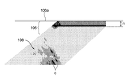
- the generation direction of the defect is different from the irradiation direction of the ultrasonic wave, the direction of the reflected wave is different. For example, referring to FIG.
- the phased array probe 100 when the irradiation direction of the ultrasonic wave u from the phased array probe 100 is perpendicular to the generation direction of the crack c, the phased array probe 100 reliably reflects the reflected wave e. I can receive it. On the other hand, even if there is a defect at the same position, if the irradiation direction of the ultrasonic wave deviates from the right angle to the crack generation direction, the reflectance of the reflected wave in the receiving direction decreases and the reflected wave can not be detected. There is a case. As a result, the defect detection accuracy is reduced.
- phased array probe 100 is disposed on the end surface 106 a of the rotor disk 106.
- the plurality of transducers 110 are arranged along the radial direction a of the rotor disk 106.
- the phased array probe 100 transmits ultrasonic waves u toward the wing groove portion 108, and a reflected wave from the wing groove portion 108 Receive
- the phased array probe 100 transmits ultrasonic waves u toward the wing groove portion 108, and a reflected wave from the wing groove portion 108 Receive
- At least one embodiment of the present invention aims to provide a method and an apparatus for ultrasonic flaw detection on a blade groove of a turbine rotor disk capable of detecting a defect such as a crack with high accuracy.
- a method of ultrasonic flaw detection of a blade groove of a turbine rotor disk An arranging step of arranging a phased array probe including a plurality of transducers capable of transmitting ultrasonic waves on the end face of the rotor disk in a parallel state in which the plurality of transducers are arranged along the circumferential direction of the rotor disk
- Ultrasonic waves are transmitted from the plurality of transducers in the parallel state in a state in which the ultrasonic wave transmission timing of each of the plurality of transducers is controlled by a first transmission pattern, and a reflected wave of the ultrasonic waves is received
- Ultrasonic waves are emitted from the plurality of transducers in the parallel state in a state in which the ultrasound transmission timing of each of the plurality of transducers is controlled by a second transmission pattern different from the first transmission pattern,
- a second transmitting and receiving step of receiving the reflected wave of the ultrasonic wave Equipped with
- the present inventors use a phased array probe 100 in which a large number of transducers 110 are juxtaposed along the radial direction (direction of arrow a) of the rotor disk end face 106a.
- the proportion of the reflected wave e received by the phased array probe 100 decreases depending on the direction of the sound wave irradiation, and it has been found that defects can not be inspected with high accuracy. And it turned out that this phenomenon becomes remarkable especially when a curved side entry type wing groove part is inspected.
- a plurality of transducers are arranged in parallel along the circumferential direction of the end face of the rotor disk, and ultrasonic waves are transmitted by the first transmission pattern and the second transmission pattern.
- the irradiation direction of the ultrasonic wave can be easily changed in the circumferential direction of the end face of the rotor disk without changing the direction of the phased array probe.
- defects such as cracks which can not be detected in the first transmission pattern can be detected in the second transmission pattern And vice versa.
- along the X direction it means that the case where the direction slightly deviates from the X direction is included is also included in the strict sense other than the case along the X direction.
- Each of the plurality of transducers has a transmitting surface capable of transmitting an ultrasonic wave,
- the transmission surface is longer in a direction intersecting with the arrangement direction than the arrangement direction of the plurality of transducers, and the arrangement direction and the ultrasonic waves emitted from the transmission surface converge on one focal point. It has a concave shape in which the central portion is recessed in the intersecting direction. According to the above configuration (2), since the ultrasonic waves transmitted from the transmission surface converge on one focal point, it is possible to increase the detection accuracy of the defect present in the vicinity of the focal point.
- the method further comprises a radial movement step of moving the probe along a radial direction of the rotor disk, Before and after the radial movement step, the first transmission and reception step and the second transmission and reception step are performed.
- the phased array probe can be in a wide range without changing the direction. The defect can be easily inspected with high accuracy.
- the method further includes an adjusting step of adjusting the number of the plurality of transducers included in the phased array probe according to the size or the shape of the wing groove.
- the phased array probe can be miniaturized by adjusting the number of transducers in accordance with the size and shape of the rotor disk and the blade groove. Therefore, even a turbine rotor with a small gap between the rotor disks and a small gap between the blade grooves can be easily inspected with high accuracy.
- each of the plurality of transducers can receive a reflected wave of the ultrasonic wave.
- the transducer serves as the transducer for ultrasonic wave transmission and the transducer for ultrasonic wave reception, defects can be inspected easily with high accuracy with a simple configuration. .
- any one of the above configurations (1) to (4) It further comprises a plurality of receiving transducers for receiving the reflected waves of the ultrasonic waves.
- the transducer for transmitting the ultrasonic wave and the transducer for receiving are separately provided, the ultrasonic wave transmitted from the transducer in the vicinity of the end face of the rotor disk (incident wave Interference with the reflected wave) can be suppressed. As a result, defects can be easily inspected with high accuracy even in a region closer to the surface of the end surface of the rotor disk.
- a blade groove portion for fixing a turbine blade provided on a rotor disk of the turbine extends in an arc shape deviated from the axial direction of the rotor disk.
- the defect is easily inspected with high accuracy by changing the irradiation direction of the ultrasonic wave.
- An ultrasonic wave flaw detection method for a turbine rotor disk according to at least one embodiment of the present invention which is used for the ultrasonic flaw detection method for a blade groove part of a turbine rotor disk according to one of (1) to (7)
- the ultrasonic flaw detector is The phased array probe including the plurality of transducers;
- the phased array probe is configured to support the plurality of transducers arranged in the radial direction of the rotor disk, and the phased array probe is arranged along the circumferential direction of the rotor disk.
- a probe support device configured to movably support; Equipped with
- the phased array probe can be easily moved along the radial direction of the rotor disk by the probe support device. Therefore, the defect can be inspected with high accuracy and easily for a wide range of one blade groove.
- the apparatus further comprises a rotor disk support device rotatably supporting the rotor disk,
- the probe support device A dolly capable of traveling in one traveling direction, An expandable post mounted on the carriage;
- An extendable arm rotatably supported in a vertical plane including the traveling direction by the support;
- the phased array probe is supported by the carriage via the arm and a post.
- the phased array probe can be easily positioned at any position on the end face of the rotor disk by rotation of the rotor disk, movement of the carriage, extension and contraction of the support, extension and contraction of the arm, and rotation of the arm. It can be arranged. For this reason, defects can be inspected with high accuracy and easily for a wide range of blade grooves.
- phased array probe in the above configuration (9), A frame provided between the phased array probe and the tip of the arm and rotatably supporting the phased array probe; An elastic member provided between the frame and the phased array probe for pressing the phased array probe toward the end face of the rotor disk.
- the phased array probe by pressing the phased array probe toward the end face of the rotor disk by the elastic member, the phased array probe can always be kept in close contact with the end face, so that the inspection can be performed with high accuracy. It can be done easily and stably.
- an ultrasonic flaw detection method and apparatus for a blade groove of a turbine rotor disk capable of detecting defects such as cracks with high accuracy are provided.
- FIG. 1 is a front view schematically showing an ultrasonic flaw detector according to an embodiment of the present invention together with a part of a rotor disk. It is an explanatory view showing a flaw detection method in the embodiment. It is a schematic diagram which shows the phased array probe of the said ultrasonic flaw detector.
- FIG. 4 is a schematic view seen from the direction B in FIG. 3 according to another embodiment of the present invention.
- FIG. 6 is a schematic view of a phased array probe according to yet another embodiment of the present invention.
- FIG. 6 is a schematic view of a phased array probe according to yet another embodiment of the present invention. It is C arrow line view in FIG.
- FIG. 1 It is a schematic diagram which shows generation
- (A) to (D) are explanatory views showing various scanning methods using a phased array probe. It is a perspective view showing a curved side entry type wing groove part. It is explanatory drawing which shows the inspection method by the conventional phased array method.
- expressions that indicate that things such as “identical”, “equal” and “homogeneous” are equal states not only represent strictly equal states, but also have tolerances or differences with which the same function can be obtained. It also represents the existing state.
- expressions representing shapes such as quadrilateral shapes and cylindrical shapes not only represent shapes such as rectangular shapes and cylindrical shapes in a geometrically strict sense, but also uneven portions and chamfers within the range where the same effect can be obtained. The shape including a part etc. shall also be expressed.
- the expressions “comprising”, “having”, “having”, “including” or “having” one component are not exclusive expressions excluding the presence of other components.
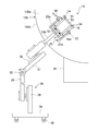
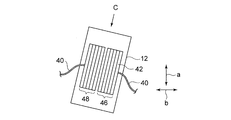
- FIG. 1 shows the configuration of an ultrasonic flaw detector 10 according to the present embodiment.
- the phased array probe 12 has a rectangular parallelepiped outer shape, is accommodated in a space formed inside the rectangular frame 14, and is fixed to the frame 14 by a fixing means such as a bolt in that state.
- the frame 14 has a pivot shaft 14a formed integrally.
- the frame 14 is inserted into the inside of a rectangular support frame 16 whose one side is open, and the pivot shaft 14 a is rotatably fitted in a hole formed in the support frame 16.
- the frame 14 is rotatably supported by the support frame 16 about the pivot shaft 14 a.
- Two springs 18 are provided on the bottom of the support frame 16 facing the frame 14.
- the spring 18 adheres the phased array probe 12 to the rotor disk end face 106 a when the frame 14 is in one direction about the pivot shaft 14 a, that is, when the phased array probe 12 is disposed on the rotor disk end face 106 a
- a spring force is applied to turn it in the direction of rotation.
- illustration of the turbine blade and the blade groove portion mounted on the outer peripheral surface 106 b of the rotor disk 106 is omitted.
- the support frame 20 is configured of a rectangular support frame 20a whose one side is open and a main shaft 20b coupled to the support frame 20a.
- the support frame 16 is fixed to the support frame 20 a by bolts 22.
- the frame body 14 and the support frame 16 each have four balls 24 at four corners on one side (the surface facing the rotor disk end surface 106 a).
- the ball 24 is rotatably mounted on the frame 14 or the support frame 16. The balls 24 allow the frame 14 and the support frame 16 to slide easily in contact with the end face 106 a of the rotor disk 106.
- the probe support device 26 has four wheels 36 and is vertically movable including the traveling direction by the carriage 34 capable of traveling in one traveling direction, the support 38 mounted on the carriage 34 and fixed thereto, and the support 38 And an arm 31 rotatably supported in the plane.
- the column 38 has a height adjustment portion 28, and the height adjustment portion 28 is slidably supported in the height direction with respect to the column 38.
- the arm 31 is rotatably supported in one plane with respect to the height adjustment unit 28 via the shaft 30.
- the arm 31 has a scanning position adjustment unit 32, and the scanning position adjustment unit 32 slidably supports the main shaft 20b of the support frame 20 in the axial direction of the main shaft 20b in the plane.
- the ultrasonic flaw detection apparatus 10 can position the phased array probe 12 at an arbitrary position on the rotor disk end surface 106 a when the plane is placed parallel to the rotor disk end surface 106 a.
- phased array probe 12 on the side of transmitting ultrasonic waves is fixed to the frame 14 so as to have substantially the same height as the frame 14 and the support frame 16.
- a cable 40 is connected to the phased array probe 12.
- a control signal is input to the phased array probe 12 via the cable 40, and a detection signal is output from the phased array probe 12.
- the inspection target of the ultrasonic flaw detection apparatus 10 is, for example, a curved side entry type wing groove portion 108 shown in FIG.
- the ultrasonic testing device 10 is moved to the rotor disk 106, and the phased array probe 12 is placed on the rotor disk end surface 106a.
- the shaft 30 so as to be orthogonal to the rotor disk end face 106a, the plane on which the arm 31 pivots can be made parallel to the rotor disk end face 106a.
- the feeler 12 can be moved in the radial direction of the rotor disk 106.
- the rotor disk 106 is rotatably supported by the rotor disk support device 39, and a radial movement process of moving the phased array probe 12 along the radial direction of the rotor disk 106 is performed.
- ultrasonic waves are emitted from the phased array probe 12 toward the wing groove portion 108 in a state of being disposed on the rotor disk end face 106 a, and the reflected wave reflected by the wing groove portion 108 is received by the phased array probe 12.
- the turbine rotor is turned manually or by a drive motor, and another radial movement step is performed. By repeating this, ultrasonic waves can be applied to all the blade grooves 108 mounted on the entire circumference of the rotor disk outer peripheral surface 106b, and all the blade grooves 108 can be inspected.
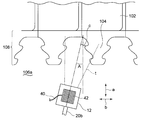
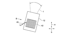
- FIG. 2 is a view showing an ultrasonic wave transmission region of the ultrasonic flaw detection apparatus 10, and FIG. 3 is an enlarged view showing the phased array probe 12.
- the phased array probe 12 has a large number of transducers 42.
- the vibrator 42 has a rod shape having a square cross section, and is arranged side by side in the circumferential direction (arrow b direction) of the rotor disk 106.
- the cable 40 sends an electric pulse to the vibrator 42 to excite the vibrator 42. Further, when the ultrasonic wave emitted by the vibrator 42 is reflected by the blade groove portion 108 and the reflected wave is received by the vibrator 42, the cable 40 sends the received reflected wave to a processing unit (not shown).
- the blade groove 108 is irradiated with ultrasonic waves from the phased array probe 12 at a skew angle A.
- the angle of the ultrasonic wave irradiation direction or the front-rear direction of the phased array probe 100 with respect to the radial direction a of the rotor disk 106 is defined as a skew angle A.
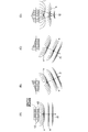
- FIGS. 9A to 9D schematically explain various scanning methods by the phased array method.
- the phased array probe 12 has a large number of transducers 42 arranged in parallel, and by controlling the timing of the pulse voltage applied to each transducer 42, the excitation time for each transducer 42 is controlled, Sound wave transmission timing (transmission pattern) can be controlled.
- Sound wave transmission timing transmission pattern
- the focal length connecting f2 can be freely changed.
- the excitation timings of the respective transducers 42 are controlled so as to enable, for example, the scans shown in FIGS. 9B and 9C.
- the transmission pattern shown in FIG. 9 (B) is adopted in the first transmission / reception step
- the transmission pattern shown in FIG. 9 (C) is adopted in the second transmission / reception step.
- the irradiation direction of the ultrasonic wave transmitted from each transducer 42 can be changed not only in the direction defined by the skew angle A but also in the circumferential direction b of the rotor disk 106. Therefore, the scanning range t of the ultrasonic wave can be widely expanded in a fan shape.
- the transmission pattern is not limited to the first transmission pattern and the second transmission pattern.
- the scanning range t can be finely analyzed by electrically and continuously scanning the irradiation direction of ultrasonic waves by employing a large number of transmission patterns.
- a plurality of transducers 42 are arranged in parallel along the circumferential direction b of the rotor disk end face 106a, and ultrasonic waves are transmitted by the first transmission pattern and the second transmission pattern.
- the irradiation direction of the ultrasonic wave can be easily changed in the circumferential direction b of the rotor disk end face 106a.
- a defect such as a crack which can not be detected in the first transmission pattern is detected in the second transmission pattern.
- defects can be enhanced over a wide range without changing the direction of the phased array probe 12 It can be easily inspected with accuracy.
- the transducer 42 serves as the transducer for ultrasonic wave transmission and the transducer for ultrasonic wave reception, defects can be easily inspected with high accuracy with a simple configuration.
- the ultrasonic flaw detection apparatus 10 has a rotor disk support device 39 so that the phased array probe 12 can be easily moved along the radial direction of the rotor disk 106. Therefore, defects can be inspected with high accuracy and easily for a wide range of one blade groove portion 108.
- phased array probe 12 can be easily disposed at any position on the rotor disk end face 106 a by the rotation of the rotor disk 106, the movement of the carriage 34, the extension and contraction of the support 38, and the extension and contraction of the arm 31. can do. For this reason, defects can be inspected with high accuracy and easily for a wide range of blade grooves 108.
- phased array probe 12 can be closely attached to the rotor disk end face 106 a by the elastic force of the spring 18, the defect detection accuracy can be further improved.
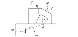
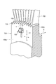
- FIG. 4 is a view of the vibrator 42 according to some embodiments as viewed from the B direction in FIG. 3.
- the ultrasound transmission surface 44 of each transducer 42 is longer in the direction intersecting with the alignment direction than the alignment direction of the transducers 42, and the ultrasound transmitted from the ultrasound transmission surface 44 Has a concave shape in which a central portion is recessed with respect to the blade groove portion 108 in a direction intersecting with the arrangement direction so that L converges to one focal point.
- the detection accuracy of the defect existing in the vicinity of the focal point can be increased. it can.
- each transducer 42 in the phased array probe 12, the longitudinal direction of each transducer 42 is inclined with respect to the rotor disk end surface 106a so that the ultrasonic wave obliquely enters the rotor disk end surface 106a.
- the respective transducers 42 are arranged in
- FIG. 5 schematically shows a phased array probe 12 according to another embodiment of the invention applied to a small turbine rotor.
- the phased array probe 12 is also miniaturized, and the number of transducers 42 is halved as compared with the embodiment.
- the number of transducers 42 in the embodiment is 32, 16 transducers 42 are disposed in the present embodiment.
- the phased array probe 12 can be miniaturized by adjusting the number of transducers 42 in accordance with the size and shape of the rotor disk 106 and the blade groove 108. Therefore, even a turbine rotor with a small gap between the rotor disks and a small gap between the blade grooves can be easily inspected with high accuracy.
- the ultrasonic wave transmitting unit 46 and the ultrasonic wave receiving unit 48 each configured of the vibrator 42 are separately configured.
- the ultrasound transmission unit 46 and the ultrasound reception unit 48 are disposed at different positions inside the phased array probe 12.
- the transmitting surface of the ultrasonic wave transmitting unit 46 and the receiving surface of the ultrasonic wave receiving unit 48 are inclined in the direction to face each other.
- the ultrasonic wave transmitter 46 transmits the ultrasonic wave u toward the blade groove 108, the reflected wave e reflected from the blade groove 108 is received by the ultrasonic wave receiver 48, and the waveform of the reflected wave e is examined to obtain defects.
- To detect the presence or size of The other configuration is the same as that of the above embodiment.
- the ultrasonic wave transmitting unit 46 and the ultrasonic wave receiving unit 48 are constituted by the same vibrator, the incident wave and the reflected wave interfere with each other to face the surface of the rotor disk end face 106a.
- Dead band n is expressed.
- the ultrasonic wave transmitting unit 46 and the ultrasonic wave receiving unit 48 by separately providing the ultrasonic wave transmitting unit 46 and the ultrasonic wave receiving unit 48, interference between the ultrasonic wave (incident wave) transmitted by the vibrator 42 and the reflected wave is generated near the rotor disk end face 106a. It can be suppressed. As a result, the dead zone n developed on the surface of the rotor disk end face 106a can be reduced, and a defect can be easily inspected with high precision even in a region closer to the surface of the rotor disk end face 106a.
- the ultrasound transmission unit 46 and the ultrasound reception unit 48 are arranged in the width direction of the phased array probe 12, and a plurality of transducers of the ultrasound transmission unit 46, and ultrasound reception The section 48 is also aligned in the width direction of the phased array probe 12.
- the transmitting surfaces of the plurality of transducers of the ultrasonic transmitting unit 46 and the receiving surfaces of the transducers of the ultrasonic receiving unit 48 are inclined with respect to the end face of the rotor disk, specifically, the transmitting surface Are inclined so that the normal of the vibrator and the normal of the vibrator intersect at the rotor disk side.
- the present invention is not limited to the above-described embodiments, and includes the embodiments in which the above-described embodiments are modified, and the embodiments in which these embodiments are appropriately combined.
- a defect such as a crack can be easily inspected with high accuracy for a blade groove portion for fixing a turbine moving blade provided on a rotor disk of a turbine.
Abstract
The following steps are included: an alignment step in which a phased-array probe that contains a plurality of transducers that are each capable of emitting ultrasound is aligned against an end surface of the rotor disc such that the plurality of transducers are in a parallel state, lined up in the circumferential direction of the rotor disc; a first transmission/reception step in which ultrasound is emitted from the plurality of transducers in the aforementioned parallel state with the timing of the ultrasound emission from the respective transducers controlled in accordance with a first emission pattern and the resulting reflected ultrasound is received; and a second transmission/reception step in which ultrasound is emitted from the plurality of transducers in the abovementioned parallel state with the timing of the ultrasound emission from the respective transducers controlled in accordance with a second emission pattern that is different from the aforementioned first emission pattern and the resulting reflected ultrasound is received.
Description
本開示は、超音波探傷法の1種であるフェイズドアレイ法を用いて、タービンロータディスクの翼溝部の欠陥を検査する方法及び該方法に用いられる装置に関する。
The present disclosure relates to a method of inspecting a defect in a blade groove of a turbine rotor disk using a phased array method, which is one type of ultrasonic flaw detection method, and an apparatus used in the method.
ガスタービンや蒸気タービンでは、タービンロータのロータディスク外周面に形成されたタービン翼を固定するための溝部(以下、「翼溝部」とも称する。)に、タービン翼の翼根部(以下、単に「翼根部」とも称する。)が挿入された状態で、タービン翼がロータディスクに固定されている。
タービンロータの翼溝部に発生する亀裂などの欠陥の有無やその大きさを検査する方法としては、磁粉探傷やレプリカ法等の検査方法を用いることができる。しかしながらこれらの方法では、タービン翼の翼根部を翼溝部から抜き取る必要があり、タービン翼の抜き取り及び検査後の再装着等、検査前後の付帯工事に多大な時間と費用を要している。 In a gas turbine or steam turbine, a blade root portion (hereinafter simply referred to as “blade”) is provided in a groove portion (hereinafter also referred to as “blade groove portion”) for fixing a turbine blade formed on a rotor disk outer peripheral surface of a turbine rotor. The turbine blade is fixed to the rotor disk with the root part inserted.
As a method of inspecting the presence or absence of a defect such as a crack generated in a blade groove portion of a turbine rotor and the size thereof, an inspection method such as magnetic powder flaw detection or a replica method can be used. However, in these methods, it is necessary to extract the blade root portion of the turbine blade from the blade groove, and additional work before and after inspection, such as removal of the turbine blade and reattachment after inspection, requires a lot of time and cost.
そのため、タービン翼を翼溝部から抜き取ることなく翼溝部を検査可能な非破壊検査技術の開発が望まれている。例えば、特許文献1及び特許文献2には、翼溝部に超音波を照射し、その反射波を受信して波形などを調べることで、翼溝部の欠陥の有無を検査可能な超音波探傷法が提案されている。
これらの超音波探傷法のうち、特許文献1で採用されているフェイズドアレイ法では、多数の振動子を有するフェイズドアレイ探触子が用られる。振動子は、フェイズドアレイ探触子の前後方向に沿って配列され、個々の振動子が超音波を発信するタイミングを独立に制御可能である。個々の振動子から発信された超音波は合成波面を形成するが、個々の振動子の発信タイミングを制御することで、合成波面の照射方向や焦点距離を自由に制御することができる。 Therefore, development of nondestructive inspection technology that can inspect the blade groove without removing the turbine blade from the blade groove is desired. For example, inPatent Document 1 and Patent Document 2, an ultrasonic flaw detection method capable of inspecting the presence or absence of a defect in a blade groove by irradiating ultrasonic waves to the blade groove and receiving a reflected wave thereof and examining a waveform or the like is disclosed. Proposed.
Among these ultrasonic flaw detection methods, in the phased array method adopted inPatent Document 1, a phased array probe having a large number of transducers is used. The transducers are arranged along the front-rear direction of the phased array probe, and can independently control the timing at which each transducer emits an ultrasonic wave. The ultrasonic waves transmitted from the individual transducers form a synthesized wavefront, but by controlling the emission timing of the individual transducers, it is possible to freely control the irradiation direction and focal length of the synthesized wavefront.
これらの超音波探傷法のうち、特許文献1で採用されているフェイズドアレイ法では、多数の振動子を有するフェイズドアレイ探触子が用られる。振動子は、フェイズドアレイ探触子の前後方向に沿って配列され、個々の振動子が超音波を発信するタイミングを独立に制御可能である。個々の振動子から発信された超音波は合成波面を形成するが、個々の振動子の発信タイミングを制御することで、合成波面の照射方向や焦点距離を自由に制御することができる。 Therefore, development of nondestructive inspection technology that can inspect the blade groove without removing the turbine blade from the blade groove is desired. For example, in
Among these ultrasonic flaw detection methods, in the phased array method adopted in
検査の際、フェイズドアレイ探触子は、検査対象物の表面に沿って前後方向に移動(走査)させられ、これにより検査範囲を変化させることができる。一方、超音波は、フェイズドアレイ探触子の前方斜め下の方向に照射される。フェイズドアレイ探触子の前後方向に対する超音波の傾斜角度は、振動子の発信タイミングを制御することにより電気的に操作可能であり、これによっても検査範囲を変化させることができる。
At the time of inspection, the phased array probe is moved (scanned) back and forth along the surface of the object to be inspected, whereby the inspection range can be changed. On the other hand, the ultrasonic waves are irradiated in the direction of the lower front of the phased array probe. The tilt angle of the ultrasonic wave with respect to the front-rear direction of the phased array probe can be electrically operated by controlling the transmission timing of the transducer, which also changes the inspection range.
フェイズドアレイ法によって翼溝部の検査を行う場合、通常、フェイズドアレイ探触子をロータディスクの端面に配置する。そして、フェイズドアレイ探触子をロータディスク端面の半径方向に移動させながら、翼溝部に向けて超音波を繰り返し照射し、翼溝部からの反射波を受信する。この場合、多数の振動子は、フェイズドアレイ探触子の移動方向であるロータディスク端面の半径方向に沿って配置され、振動子の発信タイミングを制御することにより、検査範囲の深さを変更することができる。
In the case of inspection of blade grooves by the phased array method, a phased array probe is usually disposed on the end face of the rotor disk. Then, while moving the phased array probe in the radial direction of the end face of the rotor disk, ultrasonic waves are repeatedly irradiated toward the blade groove portion, and a reflected wave from the blade groove portion is received. In this case, a large number of transducers are disposed along the radial direction of the end face of the rotor disk, which is the moving direction of the phased array probe, and the depth of the inspection range is changed by controlling the transmission timing of the transducers. be able to.
ここで、タービンロータの翼溝部では、様々な方向に亀裂などの欠陥が発生する。特に、図10に示すように、翼溝部108がロータディスク106の軸方向から逸れて円弧状に曲折しているカーブドサイドエントリ型の場合、翼溝部がロータディスクの軸方向に沿って直線状に延びている通常のサイドエントリ型と比べて、翼溝部108に発生する亀裂などの欠陥は多様な方向に発生する。
超音波探傷法では、超音波の照射方向に対し欠陥の発生方向が異なると、反射波の方向が異なってしまう。例えば、図11を参照すると、フェイズドアレイ探触子100からの超音波uの照射方向が、亀裂cの発生方向に対し直角である場合に、フェイズドアレイ探触子100は反射波eを確実に受信できる。これに対し、同じ位置に欠陥が存在したとしても、超音波の照射方向が、亀裂の発生方向に対し直角から外れると、受信方向での反射波の反射率が低下し、反射波を検出できない場合がある。この結果として、欠陥の検出精度が低下してしまう。 Here, in the blade groove portion of the turbine rotor, defects such as cracks occur in various directions. In particular, as shown in FIG. 10, in the case of a curved side entry type in which theblade groove portion 108 is bent in an arc shape deviated from the axial direction of the rotor disk 106, the blade groove portion is linear along the axial direction of the rotor disk. Defects such as cracks generated in the blade groove 108 occur in various directions as compared with the conventional side entry type that extends.
In the ultrasonic flaw detection method, if the generation direction of the defect is different from the irradiation direction of the ultrasonic wave, the direction of the reflected wave is different. For example, referring to FIG. 11, when the irradiation direction of the ultrasonic wave u from thephased array probe 100 is perpendicular to the generation direction of the crack c, the phased array probe 100 reliably reflects the reflected wave e. I can receive it. On the other hand, even if there is a defect at the same position, if the irradiation direction of the ultrasonic wave deviates from the right angle to the crack generation direction, the reflectance of the reflected wave in the receiving direction decreases and the reflected wave can not be detected. There is a case. As a result, the defect detection accuracy is reduced.
超音波探傷法では、超音波の照射方向に対し欠陥の発生方向が異なると、反射波の方向が異なってしまう。例えば、図11を参照すると、フェイズドアレイ探触子100からの超音波uの照射方向が、亀裂cの発生方向に対し直角である場合に、フェイズドアレイ探触子100は反射波eを確実に受信できる。これに対し、同じ位置に欠陥が存在したとしても、超音波の照射方向が、亀裂の発生方向に対し直角から外れると、受信方向での反射波の反射率が低下し、反射波を検出できない場合がある。この結果として、欠陥の検出精度が低下してしまう。 Here, in the blade groove portion of the turbine rotor, defects such as cracks occur in various directions. In particular, as shown in FIG. 10, in the case of a curved side entry type in which the
In the ultrasonic flaw detection method, if the generation direction of the defect is different from the irradiation direction of the ultrasonic wave, the direction of the reflected wave is different. For example, referring to FIG. 11, when the irradiation direction of the ultrasonic wave u from the
このような検出精度の低下は、フェイズドアレイ探触子の方向をロータディスクの周方向にて変化させ、超音波の照射方向と欠陥の発生方向との相対的な関係を変化させることにより防止できると考えられる。
ここで、図11に示すように、従来のフェイズドアレイ法によって翼溝部108の検査を行う場合、フェイズドアレイ探触子100をロータディスク106の端面106aに配置する。この配置では、複数の振動子110は、ロータディスク106の半径方向aに沿って配置される。そして、フェイズドアレイ探触子100をロータディスク106の半径方向aに沿って移動させながら、フェイズドアレイ探触子100から翼溝部108に向けて超音波uを発信し、翼溝部108からの反射波を受信する。
このような従来の方法では、フェイズドアレイ探触子100の方向をロータディスク端面106aの周方向bにて変化させようとした場合、半径方向aでの位置についてのみならず、周方向についてもフェイズドアレイ探触子100を走査しなければならなくなり、走査が難しくなる。 Such a decrease in detection accuracy can be prevented by changing the direction of the phased array probe in the circumferential direction of the rotor disk and changing the relative relationship between the direction of ultrasonic wave irradiation and the direction of defect generation. it is conceivable that.
Here, as shown in FIG. 11, in the case where theblade groove portion 108 is inspected by the conventional phased array method, the phased array probe 100 is disposed on the end surface 106 a of the rotor disk 106. In this arrangement, the plurality of transducers 110 are arranged along the radial direction a of the rotor disk 106. Then, while moving the phased array probe 100 along the radial direction a of the rotor disk 106, the phased array probe 100 transmits ultrasonic waves u toward the wing groove portion 108, and a reflected wave from the wing groove portion 108 Receive
In such a conventional method, when it is intended to change the direction of thephased array probe 100 in the circumferential direction b of the rotor disk end face 106a, not only the position in the radial direction a but also the phased direction in the circumferential direction The array probe 100 has to be scanned, which makes scanning difficult.
ここで、図11に示すように、従来のフェイズドアレイ法によって翼溝部108の検査を行う場合、フェイズドアレイ探触子100をロータディスク106の端面106aに配置する。この配置では、複数の振動子110は、ロータディスク106の半径方向aに沿って配置される。そして、フェイズドアレイ探触子100をロータディスク106の半径方向aに沿って移動させながら、フェイズドアレイ探触子100から翼溝部108に向けて超音波uを発信し、翼溝部108からの反射波を受信する。
このような従来の方法では、フェイズドアレイ探触子100の方向をロータディスク端面106aの周方向bにて変化させようとした場合、半径方向aでの位置についてのみならず、周方向についてもフェイズドアレイ探触子100を走査しなければならなくなり、走査が難しくなる。 Such a decrease in detection accuracy can be prevented by changing the direction of the phased array probe in the circumferential direction of the rotor disk and changing the relative relationship between the direction of ultrasonic wave irradiation and the direction of defect generation. it is conceivable that.
Here, as shown in FIG. 11, in the case where the
In such a conventional method, when it is intended to change the direction of the
本発明の少なくとも一実施形態は、係る従来技術の課題に鑑み、亀裂等の欠陥を高精度に検出可能なタービンロータディスクの翼溝部の超音波探傷方法及び装置を提供することを目的とする。
SUMMARY OF THE INVENTION In view of the problems of the related art, at least one embodiment of the present invention aims to provide a method and an apparatus for ultrasonic flaw detection on a blade groove of a turbine rotor disk capable of detecting a defect such as a crack with high accuracy.
(1)本発明の少なくとも一実施形態に係るタービンロータディスクの翼溝部の超音波探傷方法は、
それぞれ超音波を発信可能な複数の振動子を含むフェイズドアレイ探触子を、前記複数の振動子が前記ロータディスクの周方向に沿って並んだ並列状態で前記ロータディスクの端面に配置する配置工程と、
前記並列状態にある前記複数の振動子から、前記複数の振動子の各々の超音波発信時期を第1の発信パターンで制御した状態で超音波を発信させ、該超音波の反射波を受信する第1の送受信工程と、
前記並列状態にある前記複数の振動子から、前記複数の振動子の各々の超音波発信時期を前記第1の発信パターンとは異なる第2の発信パターンで制御した状態で超音波を発信させ、該超音波の反射波を受信する第2の送受信工程と、
を備える。 (1) A method of ultrasonic flaw detection of a blade groove of a turbine rotor disk according to at least one embodiment of the present invention,
An arranging step of arranging a phased array probe including a plurality of transducers capable of transmitting ultrasonic waves on the end face of the rotor disk in a parallel state in which the plurality of transducers are arranged along the circumferential direction of the rotor disk When,
Ultrasonic waves are transmitted from the plurality of transducers in the parallel state in a state in which the ultrasonic wave transmission timing of each of the plurality of transducers is controlled by a first transmission pattern, and a reflected wave of the ultrasonic waves is received A first transmission and reception process;
Ultrasonic waves are emitted from the plurality of transducers in the parallel state in a state in which the ultrasound transmission timing of each of the plurality of transducers is controlled by a second transmission pattern different from the first transmission pattern, A second transmitting and receiving step of receiving the reflected wave of the ultrasonic wave;
Equipped with
本発明者等は、図11に示すように、多数の振動子110が、ロータディスク端面106aの半径方向(矢印a方向)に沿って並置されたフェイズドアレイ探触子100を用いたとき、超音波の照射方向によってフェイズドアレイ探触子100が受信する反射波eの割合が低下し、欠陥を高精度にて検査できないという知見を得た。そしてこの現象は、特にカーブドサイドエントリ型の翼溝部を検査したとき顕著となることが判明した。これは、本発明者等の知見によれば、カーブドサイドエントリ型の翼溝部の場合、翼溝部がロータディスクの軸方向から外れて湾曲しているため、亀裂等の欠陥の発生方向が多様であるためと考えられる。
このような知見に基づき、本発明者等は、欠陥の検査精度を向上させるために、超音波の照射方向をロータディスクの周方向に変化させることに想到した。しかしながら、従来のように、複数の振動子をロータディスク端面の半径方向に並列に並べて配置し、振動子の発信パターンを制御するのみでは、超音波の照射方向をロータディスクの周方向にて走査することができなかった。 The present inventors, as shown in FIG. 11, use aphased array probe 100 in which a large number of transducers 110 are juxtaposed along the radial direction (direction of arrow a) of the rotor disk end face 106a. The proportion of the reflected wave e received by the phased array probe 100 decreases depending on the direction of the sound wave irradiation, and it has been found that defects can not be inspected with high accuracy. And it turned out that this phenomenon becomes remarkable especially when a curved side entry type wing groove part is inspected. This is because, according to the knowledge of the present inventors, in the case of a curved side entry type blade groove portion, since the blade groove portion is curved out of the axial direction of the rotor disk, the generation direction of defects such as cracks is various. It is thought that there is.
Based on such findings, the present inventors have conceived of changing the irradiation direction of ultrasonic waves in the circumferential direction of the rotor disk in order to improve the inspection accuracy of defects. However, as in the prior art, by merely arranging a plurality of transducers in parallel in the radial direction of the end face of the rotor disk and controlling the transmission pattern of the transducers, the irradiation direction of ultrasonic waves is scanned in the circumferential direction of the rotor disk I could not do it.
このような知見に基づき、本発明者等は、欠陥の検査精度を向上させるために、超音波の照射方向をロータディスクの周方向に変化させることに想到した。しかしながら、従来のように、複数の振動子をロータディスク端面の半径方向に並列に並べて配置し、振動子の発信パターンを制御するのみでは、超音波の照射方向をロータディスクの周方向にて走査することができなかった。 The present inventors, as shown in FIG. 11, use a
Based on such findings, the present inventors have conceived of changing the irradiation direction of ultrasonic waves in the circumferential direction of the rotor disk in order to improve the inspection accuracy of defects. However, as in the prior art, by merely arranging a plurality of transducers in parallel in the radial direction of the end face of the rotor disk and controlling the transmission pattern of the transducers, the irradiation direction of ultrasonic waves is scanned in the circumferential direction of the rotor disk I could not do it.
この点、上記構成(1)によれば、複数の振動子をロータディスク端面の周方向に沿って並列に配置し、第1の発信パターンと第2の発信パターンで超音波を発信することで、フェイズドアレイ探触子の方向を変化させなくても、超音波の照射方向をロータディスク端面の周方向にて容易に変更することができる。
そして、超音波の照射方向をロータディスク端面の周方向にて変更することにより、例えば、第1の発信パターンでは検出できなかった亀裂等の欠陥を、第2の発信パターンでは検出することが可能になり、この逆も可能になる。
なお、本明細書で「X方向に沿って」と表現するときは、厳密な意味でX方向に沿う場合以外に、X方向から多少外れた方向に沿う場合も含むことを意味する。 In this respect, according to the above configuration (1), a plurality of transducers are arranged in parallel along the circumferential direction of the end face of the rotor disk, and ultrasonic waves are transmitted by the first transmission pattern and the second transmission pattern. The irradiation direction of the ultrasonic wave can be easily changed in the circumferential direction of the end face of the rotor disk without changing the direction of the phased array probe.
Then, by changing the irradiation direction of the ultrasonic wave in the circumferential direction of the end face of the rotor disk, for example, defects such as cracks which can not be detected in the first transmission pattern can be detected in the second transmission pattern And vice versa.
In addition, when expressing in this specification as "along the X direction", it means that the case where the direction slightly deviates from the X direction is included is also included in the strict sense other than the case along the X direction.
(2)幾つかの実施形態では、上記(1)の構成において、
前記複数の振動子の各々は、超音波を発信可能な発信面を有し、
前記発信面は、前記複数の振動子の配列方向よりも該配列方向と交差する方向に長く、且つ、該発信面から発信された超音波が1つの焦点に収束するように、前記配列方向と交差する方向にて中央部が凹んだ凹面形状を有する。
上記構成(2)によれば、発信面から発信された超音波が1つの焦点に収束するので、焦点近傍に存在する欠陥の検出精度を高くすることができる。 (2) In some embodiments, in the configuration of (1) above,
Each of the plurality of transducers has a transmitting surface capable of transmitting an ultrasonic wave,
The transmission surface is longer in a direction intersecting with the arrangement direction than the arrangement direction of the plurality of transducers, and the arrangement direction and the ultrasonic waves emitted from the transmission surface converge on one focal point. It has a concave shape in which the central portion is recessed in the intersecting direction.
According to the above configuration (2), since the ultrasonic waves transmitted from the transmission surface converge on one focal point, it is possible to increase the detection accuracy of the defect present in the vicinity of the focal point.
(3)幾つかの実施形態では、上記構成(1)又は(2)において、
前記探触子を前記ロータディスクの半径方向に沿って移動させる半径方向移動工程を更に備え、
前記半径方向移動工程の前及び後に、前記第1の送受信工程及び前記第2の送受信工程を実行する。
上記構成(3)によれば、半径方向移動工程の前及び後に、第1の送受信工程及び第2の送受信工程を行うことにより、フェイズドアレイ探触子の方向を変えなくても、広い範囲に渡って、欠陥を高精度にて容易に検査することができる。 (3) In some embodiments, in the above configuration (1) or (2),
The method further comprises a radial movement step of moving the probe along a radial direction of the rotor disk,
Before and after the radial movement step, the first transmission and reception step and the second transmission and reception step are performed.
According to the above configuration (3), by performing the first transmission / reception step and the second transmission / reception step before and after the radial movement step, the phased array probe can be in a wide range without changing the direction. The defect can be easily inspected with high accuracy.
(4)幾つかの実施形態では、上記構成(1)乃至(3)の何れか一つにおいて、
前記翼溝部の大きさ又は形状に応じて、前記フェイズドアレイ探触子に含まれる前記複数の振動子の数を調整する調整工程を更に備える。
上記構成(4)によれば、ロータディスク及び翼溝部の大きさ及び形状に応じて、振動子の数を調整することで、フェイズドアレイ探触子の小型化を図ることができる。そのため、ロータディスク間の隙間や、翼溝部の間隔が小さいタービンロータでも、高精度にて容易に検査することができる。 (4) In some embodiments, in any one of the above configurations (1) to (3),
The method further includes an adjusting step of adjusting the number of the plurality of transducers included in the phased array probe according to the size or the shape of the wing groove.
According to the above configuration (4), the phased array probe can be miniaturized by adjusting the number of transducers in accordance with the size and shape of the rotor disk and the blade groove. Therefore, even a turbine rotor with a small gap between the rotor disks and a small gap between the blade grooves can be easily inspected with high accuracy.
(5)幾つかの実施形態では、上記構成(1)乃至(4)の何れか一つにおいて
前記複数の振動子の各々は前記超音波の反射波を受信可能である。
上記構成(5)によれば、振動子が超音波発信用振動子と超音波受信用振動子を兼ねているので、簡単な構成にて、欠陥を高精度にて容易に検査することができる。 (5) In some embodiments, in any one of the configurations (1) to (4), each of the plurality of transducers can receive a reflected wave of the ultrasonic wave.
According to the above configuration (5), since the transducer serves as the transducer for ultrasonic wave transmission and the transducer for ultrasonic wave reception, defects can be inspected easily with high accuracy with a simple configuration. .
(6)幾つかの実施形態では、上記構成(1)乃至(4)の何れか一つにおいて、
前記超音波の反射波を受信するための複数の受信用振動子を更に備える。
上記構成(6)によれば、超音波を発信するための振動子と受信するための振動子を別々に設けたことにより、ロータディスクの端面近傍で、振動子が発信した超音波(入射波)と反射波の干渉を抑制することができる。この結果、ロータディスクの端面のより表面に近い領域においても、欠陥を高精度にて容易に検査することができる。 (6) In some embodiments, in any one of the above configurations (1) to (4),
It further comprises a plurality of receiving transducers for receiving the reflected waves of the ultrasonic waves.
According to the above configuration (6), since the transducer for transmitting the ultrasonic wave and the transducer for receiving are separately provided, the ultrasonic wave transmitted from the transducer in the vicinity of the end face of the rotor disk (incident wave Interference with the reflected wave) can be suppressed. As a result, defects can be easily inspected with high accuracy even in a region closer to the surface of the end surface of the rotor disk.
(7)幾つかの実施形態では、上記構成(1)乃至(6)の何れか一つにおいて、
前記タービンのロータディスクに設けられたタービン翼を固定するための翼溝部は、前記ロータディスクの軸方向から逸れて円弧状に延びている。
上記構成(7)では、翼溝部が円弧状に延びており、欠陥の発生方向が様々であっても、超音波の照射方向を変化させることにより、欠陥を高精度にて容易に検査することができる。 (7) In some embodiments, in any one of the above configurations (1) to (6),
A blade groove portion for fixing a turbine blade provided on a rotor disk of the turbine extends in an arc shape deviated from the axial direction of the rotor disk.
In the above configuration (7), even if the wing groove portion extends in an arc shape and the defect generation direction is various, the defect is easily inspected with high accuracy by changing the irradiation direction of the ultrasonic wave. Can.
(8)本発明の少なくとも一実施形態に係る、上記(1)乃至(7)の一つに記載のタービンロータディスクの翼溝部の超音波探傷方法に用いられる、タービンロータディスクの翼溝部の超音波探傷装置は、
前記複数の振動子を含む前記フェイズドアレイ探触子と、
前記フェイズドアレイ探触子を、前記複数の振動子が前記ロータディスクの半径方向に並んだ状態で支持するように構成され、且つ、前記フェイズドアレイ探触子を前記ロータディスクの周方向に沿って移動可能に支持するように構成された探触子支持装置と、
を備える。 (8) An ultrasonic wave flaw detection method for a turbine rotor disk according to at least one embodiment of the present invention, which is used for the ultrasonic flaw detection method for a blade groove part of a turbine rotor disk according to one of (1) to (7) The ultrasonic flaw detector is
The phased array probe including the plurality of transducers;
The phased array probe is configured to support the plurality of transducers arranged in the radial direction of the rotor disk, and the phased array probe is arranged along the circumferential direction of the rotor disk. A probe support device configured to movably support;
Equipped with
上記構成(8)によれば、探触子支持装置により、フェイズドアレイ探触子をロータディスクの半径方向に沿って容易に移動させることができる。このため、1つの翼溝部について広範囲に渡って、欠陥を高精度且つ容易に検査することができる。
According to the above configuration (8), the phased array probe can be easily moved along the radial direction of the rotor disk by the probe support device. Therefore, the defect can be inspected with high accuracy and easily for a wide range of one blade groove.
(9)幾つかの実施形態では、上記構成(8)において、
前記ロータディスクを回転可能に支持するロータディスク支持装置を更に備え、
前記探触子支持装置は、
一の走行方向に走行可能な台車と、
前記台車に搭載された伸縮可能な支柱と、
前記支柱によって前記走行方向を含む鉛直面内で回動可能に支持された伸縮可能なアームとを含み、
前記フェイズドアレイ探触子は、前記アーム及び支柱を介して前記台車により支持されている。 (9) In some embodiments, in the above configuration (8),
The apparatus further comprises a rotor disk support device rotatably supporting the rotor disk,
The probe support device
A dolly capable of traveling in one traveling direction,
An expandable post mounted on the carriage;
An extendable arm rotatably supported in a vertical plane including the traveling direction by the support;
The phased array probe is supported by the carriage via the arm and a post.
上記構成(9)によれば、ロータディスクの回転、台車の移動、支柱の伸縮、アームの伸縮、及びアームの回動により、フェイズドアレイ探触子をロータディスクの端面の任意の位置に容易に配置することができる。このため、複数の翼溝部について広範に渡って、欠陥を高精度且つ容易に検査することができる。
According to the above configuration (9), the phased array probe can be easily positioned at any position on the end face of the rotor disk by rotation of the rotor disk, movement of the carriage, extension and contraction of the support, extension and contraction of the arm, and rotation of the arm. It can be arranged. For this reason, defects can be inspected with high accuracy and easily for a wide range of blade grooves.
(10)幾つかの実施形態では、上記構成(9)において、
前記フェイズドアレイ探触子と前記アームの先端との間に設けられ、前記フェイズドアレイ探触子を回動可能に支持する枠体と、
前記枠体と前記フェイズドアレイ探触子との間に設けられ、前記フェイズドアレイ探触子を前記ロータディスクの端面に向かって押し付けるための弾性部材とを更に備える。
上記構成(10)によれば、弾性部材によってフェイズドアレイ探触子をロータディスクの端面に向かって押し付けることで、フェイズドアレイ探触子を端面に対し常に密着させることができ、高精度な検査を容易且つ安定して行うことができる。 (10) In some embodiments, in the above configuration (9),
A frame provided between the phased array probe and the tip of the arm and rotatably supporting the phased array probe;
An elastic member provided between the frame and the phased array probe for pressing the phased array probe toward the end face of the rotor disk.
According to the above configuration (10), by pressing the phased array probe toward the end face of the rotor disk by the elastic member, the phased array probe can always be kept in close contact with the end face, so that the inspection can be performed with high accuracy. It can be done easily and stably.
本発明の少なくとも一実施形態によれば、亀裂等の欠陥を高精度に検出可能なタービンロータディスクの翼溝部の超音波探傷方法及び装置が提供される。
According to at least one embodiment of the present invention, an ultrasonic flaw detection method and apparatus for a blade groove of a turbine rotor disk capable of detecting defects such as cracks with high accuracy are provided.
以下、添付図面を参照して本発明の幾つかの実施形態について説明する。ただし、実施形態として記載され又は図面に示されている構成部品の寸法、材質、形状、その相対的配置等は、本発明の範囲をこれに限定する趣旨ではなく、単なる説明例にすぎない。
例えば、「ある方向に」、「ある方向に沿って」、「平行」、「直交」、「中心」、「同心」或いは「同軸」等の相対的或いは絶対的な配置を表す表現は、厳密にそのような配置を表すのみならず、公差、若しくは、同じ機能が得られる程度の角度や距離をもって相対的に変位している状態も表すものとする。
例えば、「同一」、「等しい」及び「均質」等の物事が等しい状態であることを表す表現は、厳密に等しい状態を表すのみならず、公差、若しくは、同じ機能が得られる程度の差が存在している状態も表すものとする。
例えば、四角形状や円筒形状等の形状を表す表現は、幾何学的に厳密な意味での四角形状や円筒形状等の形状を表すのみならず、同じ効果が得られる範囲で、凹凸部や面取り部等を含む形状も表すものとする。
一方、一つの構成要素を「備える」、「具える」、「具備する」、「含む」、又は「有する」という表現は、他の構成要素の存在を除外する排他的な表現ではない。 Hereinafter, some embodiments of the present invention will be described with reference to the accompanying drawings. However, the dimensions, materials, shapes, relative arrangements and the like of the components described as the embodiments or shown in the drawings are not intended to limit the scope of the present invention to these, but are merely illustrative examples.
For example, a representation representing a relative or absolute arrangement such as “in a direction”, “along a direction”, “parallel”, “orthogonal”, “center”, “concentric” or “coaxial” is strictly Not only does it represent such an arrangement, but also represents a state of relative displacement with an angle or distance that allows the same function to be obtained.
For example, expressions that indicate that things such as "identical", "equal" and "homogeneous" are equal states not only represent strictly equal states, but also have tolerances or differences with which the same function can be obtained. It also represents the existing state.
For example, expressions representing shapes such as quadrilateral shapes and cylindrical shapes not only represent shapes such as rectangular shapes and cylindrical shapes in a geometrically strict sense, but also uneven portions and chamfers within the range where the same effect can be obtained. The shape including a part etc. shall also be expressed.
On the other hand, the expressions "comprising", "having", "having", "including" or "having" one component are not exclusive expressions excluding the presence of other components.
本発明の一実施形態を図1~図3に基づいて説明する。
図1は本実施形態に係る超音波探傷装置10の構成を示している。フェイズドアレイ探触子12は直方体形状の外形を有し、四角形の枠体14の内側に形成された空間に収容され、その状態でボルトなどの固定手段で枠体14に固定される。
枠体14は一体に形成された回動軸14aを有している。枠体14は一辺が開放された四角形の支持枠16の内部に挿入され、回動軸14aは支持枠16に形成された孔に回動
可能に嵌合されている。これによって、枠体14は回動軸14aを中心に支持枠16に回動可能に支持される。 An embodiment of the present invention will be described based on FIGS. 1 to 3.
FIG. 1 shows the configuration of anultrasonic flaw detector 10 according to the present embodiment. The phased array probe 12 has a rectangular parallelepiped outer shape, is accommodated in a space formed inside the rectangular frame 14, and is fixed to the frame 14 by a fixing means such as a bolt in that state.
Theframe 14 has a pivot shaft 14a formed integrally. The frame 14 is inserted into the inside of a rectangular support frame 16 whose one side is open, and the pivot shaft 14 a is rotatably fitted in a hole formed in the support frame 16. Thus, the frame 14 is rotatably supported by the support frame 16 about the pivot shaft 14 a.
図1は本実施形態に係る超音波探傷装置10の構成を示している。フェイズドアレイ探触子12は直方体形状の外形を有し、四角形の枠体14の内側に形成された空間に収容され、その状態でボルトなどの固定手段で枠体14に固定される。
枠体14は一体に形成された回動軸14aを有している。枠体14は一辺が開放された四角形の支持枠16の内部に挿入され、回動軸14aは支持枠16に形成された孔に回動
可能に嵌合されている。これによって、枠体14は回動軸14aを中心に支持枠16に回動可能に支持される。 An embodiment of the present invention will be described based on FIGS. 1 to 3.
FIG. 1 shows the configuration of an
The
枠体14に対面した支持枠16の底辺に2個のバネ18が設けられている。バネ18は枠体14を回動軸14aを中心に一方の方向、即ち、フェイズドアレイ探触子12がロータディスク端面106aに配置されたとき、フェイズドアレイ探触子12をロータディスク端面106aへ密着させる方向へ回動させるバネ力を付加している。
なお、図1では、ロータディスク106の外周面106bに装着されたタービン翼及び翼溝部の図示を省略している。 Two springs 18 are provided on the bottom of thesupport frame 16 facing the frame 14. The spring 18 adheres the phased array probe 12 to the rotor disk end face 106 a when the frame 14 is in one direction about the pivot shaft 14 a, that is, when the phased array probe 12 is disposed on the rotor disk end face 106 a A spring force is applied to turn it in the direction of rotation.
In FIG. 1, illustration of the turbine blade and the blade groove portion mounted on the outerperipheral surface 106 b of the rotor disk 106 is omitted.
なお、図1では、ロータディスク106の外周面106bに装着されたタービン翼及び翼溝部の図示を省略している。 Two springs 18 are provided on the bottom of the
In FIG. 1, illustration of the turbine blade and the blade groove portion mounted on the outer
支持フレーム20は、一辺が開放された四角形の支持枠20aと、支持枠20aに結合した主軸20bとで構成されている。支持枠16は支持枠20aにボルト22によって固定されている。
枠体14及び支持枠16は、片面(ロータディスク端面106aに対面する側の面)の4隅に夫々4個のボール24を有している。ボール24は枠体14又は支持枠16に転動自在に装着されている。ボール24によって、枠体14及び支持枠16がロータディスク106の端面106aに接した状態で容易に滑動できる。 Thesupport frame 20 is configured of a rectangular support frame 20a whose one side is open and a main shaft 20b coupled to the support frame 20a. The support frame 16 is fixed to the support frame 20 a by bolts 22.
Theframe body 14 and the support frame 16 each have four balls 24 at four corners on one side (the surface facing the rotor disk end surface 106 a). The ball 24 is rotatably mounted on the frame 14 or the support frame 16. The balls 24 allow the frame 14 and the support frame 16 to slide easily in contact with the end face 106 a of the rotor disk 106.
枠体14及び支持枠16は、片面(ロータディスク端面106aに対面する側の面)の4隅に夫々4個のボール24を有している。ボール24は枠体14又は支持枠16に転動自在に装着されている。ボール24によって、枠体14及び支持枠16がロータディスク106の端面106aに接した状態で容易に滑動できる。 The
The
探触子支持装置26は、4個の車輪36を有し、一の走行方向に走行可能な台車34と、台車34に搭載され固定された支柱38と、支柱38によって前記走行方向を含む鉛直面内で回動可能に支持されたアーム31とを含んでいる。支柱38は高さ調整部28を有し、高さ調整部28は支柱38に対して高さ方向にスライド可能に支持されている。
アーム31は高さ調整部28に対して軸30を介して一平面内で回動可能に支持されている。アーム31は走査位置調整部32を有し、走査位置調整部32は支持フレーム20の主軸20bを前記平面内で主軸20bの軸方向にスライド可能に支持している。
超音波探傷装置10は、前記平面がロータディスク端面106aと平行となるように置かれたとき、フェイズドアレイ探触子12をロータディスク端面106aの任意の位置に配置できる。 Theprobe support device 26 has four wheels 36 and is vertically movable including the traveling direction by the carriage 34 capable of traveling in one traveling direction, the support 38 mounted on the carriage 34 and fixed thereto, and the support 38 And an arm 31 rotatably supported in the plane. The column 38 has a height adjustment portion 28, and the height adjustment portion 28 is slidably supported in the height direction with respect to the column 38.
Thearm 31 is rotatably supported in one plane with respect to the height adjustment unit 28 via the shaft 30. The arm 31 has a scanning position adjustment unit 32, and the scanning position adjustment unit 32 slidably supports the main shaft 20b of the support frame 20 in the axial direction of the main shaft 20b in the plane.
The ultrasonicflaw detection apparatus 10 can position the phased array probe 12 at an arbitrary position on the rotor disk end surface 106 a when the plane is placed parallel to the rotor disk end surface 106 a.
アーム31は高さ調整部28に対して軸30を介して一平面内で回動可能に支持されている。アーム31は走査位置調整部32を有し、走査位置調整部32は支持フレーム20の主軸20bを前記平面内で主軸20bの軸方向にスライド可能に支持している。
超音波探傷装置10は、前記平面がロータディスク端面106aと平行となるように置かれたとき、フェイズドアレイ探触子12をロータディスク端面106aの任意の位置に配置できる。 The
The
The ultrasonic
フェイズドアレイ探触子12の超音波を発信する側の面は枠体14及び支持枠16とほぼ同一高さとなるように枠体14に固定されている。フェイズドアレイ探触子12にはケーブル40が接続されている。ケーブル40を介して、フェイズドアレイ探触子12に制御信号が入力され、検出信号がフェイズドアレイ探触子12から出力される。
The surface of the phased array probe 12 on the side of transmitting ultrasonic waves is fixed to the frame 14 so as to have substantially the same height as the frame 14 and the support frame 16. A cable 40 is connected to the phased array probe 12. A control signal is input to the phased array probe 12 via the cable 40, and a detection signal is output from the phased array probe 12.
超音波探傷装置10の検査対象は、例えば、図10に示すカーブドサイドエントリ型の翼溝部108である。超音波探傷装置10をロータディスク106まで移動させ、フェイズドアレイ探触子12をロータディスク端面106aに配置する。この際、軸30がロータディスク端面106aと直交するように配置することで、アーム31が回動する平面をロータディスク端面106aと平行にすることができ、走査位置調整部32によって、フェイズドアレイ探触子12をロータディスク106の半径方向へ移動させることができる。
The inspection target of the ultrasonic flaw detection apparatus 10 is, for example, a curved side entry type wing groove portion 108 shown in FIG. The ultrasonic testing device 10 is moved to the rotor disk 106, and the phased array probe 12 is placed on the rotor disk end surface 106a. At this time, by arranging the shaft 30 so as to be orthogonal to the rotor disk end face 106a, the plane on which the arm 31 pivots can be made parallel to the rotor disk end face 106a. The feeler 12 can be moved in the radial direction of the rotor disk 106.
ロータディスク106はロータディスク支持装置39で回転可能に支持しておき、フェイズドアレイ探触子12をロータディスク106の半径方向に沿って移動させる半径方向移動工程を実施する。
この間、ロータディスク端面106aに配置された状態でフェイズドアレイ探触子12から翼溝部108に向けて超音波を発信し、翼溝部108で反射した反射波をフェイズドアレイ探触子12で受信する。この反射波の波形を調べることで、亀裂などの欠陥の有無や寸法を検査する。
次に、タービンロータを人手又は駆動モータで回し、もう一度半径方向移動工程を実施する。これを繰り返すことで、ロータディスク外周面106bの全周に装着されたすべての翼溝部108に対して超音波を照射でき、すべての翼溝部108を検査できる。 Therotor disk 106 is rotatably supported by the rotor disk support device 39, and a radial movement process of moving the phased array probe 12 along the radial direction of the rotor disk 106 is performed.
During this time, ultrasonic waves are emitted from the phasedarray probe 12 toward the wing groove portion 108 in a state of being disposed on the rotor disk end face 106 a, and the reflected wave reflected by the wing groove portion 108 is received by the phased array probe 12. By examining the waveform of the reflected wave, the presence or size of a defect such as a crack is inspected.
Next, the turbine rotor is turned manually or by a drive motor, and another radial movement step is performed. By repeating this, ultrasonic waves can be applied to all theblade grooves 108 mounted on the entire circumference of the rotor disk outer peripheral surface 106b, and all the blade grooves 108 can be inspected.
この間、ロータディスク端面106aに配置された状態でフェイズドアレイ探触子12から翼溝部108に向けて超音波を発信し、翼溝部108で反射した反射波をフェイズドアレイ探触子12で受信する。この反射波の波形を調べることで、亀裂などの欠陥の有無や寸法を検査する。
次に、タービンロータを人手又は駆動モータで回し、もう一度半径方向移動工程を実施する。これを繰り返すことで、ロータディスク外周面106bの全周に装着されたすべての翼溝部108に対して超音波を照射でき、すべての翼溝部108を検査できる。 The
During this time, ultrasonic waves are emitted from the phased
Next, the turbine rotor is turned manually or by a drive motor, and another radial movement step is performed. By repeating this, ultrasonic waves can be applied to all the
図2は超音波探傷装置10の超音波発信領域を示す図であり、図3はフェイズドアレイ探触子12を示す拡大図である。
図3に示すように、フェイズドアレイ探触子12は多数の振動子42を有している。振動子42は断面が四角形の棒状を有し、ロータディスク106の周方向(矢印b方向)に並べて配置されている。ケーブル40は、振動子42に電気パルスを送り、振動子42を励振させる。また、振動子42が照射した超音波が翼溝部108で反射し、その反射波を振動子42が受信したとき、ケーブル40は受信した反射波を処理部(不図示)に送る。 FIG. 2 is a view showing an ultrasonic wave transmission region of the ultrasonicflaw detection apparatus 10, and FIG. 3 is an enlarged view showing the phased array probe 12. As shown in FIG.
As shown in FIG. 3, the phasedarray probe 12 has a large number of transducers 42. The vibrator 42 has a rod shape having a square cross section, and is arranged side by side in the circumferential direction (arrow b direction) of the rotor disk 106. The cable 40 sends an electric pulse to the vibrator 42 to excite the vibrator 42. Further, when the ultrasonic wave emitted by the vibrator 42 is reflected by the blade groove portion 108 and the reflected wave is received by the vibrator 42, the cable 40 sends the received reflected wave to a processing unit (not shown).
図3に示すように、フェイズドアレイ探触子12は多数の振動子42を有している。振動子42は断面が四角形の棒状を有し、ロータディスク106の周方向(矢印b方向)に並べて配置されている。ケーブル40は、振動子42に電気パルスを送り、振動子42を励振させる。また、振動子42が照射した超音波が翼溝部108で反射し、その反射波を振動子42が受信したとき、ケーブル40は受信した反射波を処理部(不図示)に送る。 FIG. 2 is a view showing an ultrasonic wave transmission region of the ultrasonic
As shown in FIG. 3, the phased
図2に示すように、フェイズドアレイ探触子12からスキュー角Aで翼溝部108に超音波を照射する。なお、図2に示したように、ロータディスク106の半径方向aに対する、フェイズドアレイ探触子100の超音波照射方向又は前後方向の角度をスキュー角Aと定義する。
As shown in FIG. 2, the blade groove 108 is irradiated with ultrasonic waves from the phased array probe 12 at a skew angle A. Note that, as shown in FIG. 2, the angle of the ultrasonic wave irradiation direction or the front-rear direction of the phased array probe 100 with respect to the radial direction a of the rotor disk 106 is defined as a skew angle A.
ここで、図9(A)~(D)はフェイズドアレイ法による各種スキャン法を模式的に説明している。フェイズドアレイ探触子12は並列に並べられた多数の振動子42を有し、各振動子42に付加するパルス電圧のタイミングを制御することで、振動子42毎の励振時間を制御し、超音波発信時期(発信パターン)を制御することができる。これによって、各振動子42から発信された超音波uの波面が合成して形成される合成波面(各超音波uの包絡面)sの照射方向や、合成波面sが線焦点f1や点焦点f2を結ぶ焦点距離を自由に変えることができる。
Here, FIGS. 9A to 9D schematically explain various scanning methods by the phased array method. The phased array probe 12 has a large number of transducers 42 arranged in parallel, and by controlling the timing of the pulse voltage applied to each transducer 42, the excitation time for each transducer 42 is controlled, Sound wave transmission timing (transmission pattern) can be controlled. Thereby, the irradiation direction of the combined wavefront (envelope surface of each ultrasound u) s formed by combining the wavefronts of the ultrasonic waves u transmitted from the respective transducers 42, the combined wavefront s has a line focus f1 or a point focus The focal length connecting f2 can be freely changed.
各振動子42相互の励振タイミングは、例えば図9(B)及び(C)に示すスキャンが可能なように制御されている。例えば、図9(B)に示す発信パターンが第1の送受信工程で採用され、図9(C)に示す発信パターンが第2の送受信工程で採用される。
これによって、各振動子42から発信される超音波の照射方向をスキュー角Aで規定される方向のみならず、ロータディスク106の周方向bに変化させることができる。そのため、超音波の走査範囲tを扇形状に広範囲に広げることができる。なお、発信パターンは、第1の発信パターン及び第2の発信パターンに限定されない。例えば、多数の発信パターンを採用して超音波の照射方向を電気的且つ連続的に走査することで、走査範囲tを細かく分析することができる。 The excitation timings of therespective transducers 42 are controlled so as to enable, for example, the scans shown in FIGS. 9B and 9C. For example, the transmission pattern shown in FIG. 9 (B) is adopted in the first transmission / reception step, and the transmission pattern shown in FIG. 9 (C) is adopted in the second transmission / reception step.
By this, the irradiation direction of the ultrasonic wave transmitted from eachtransducer 42 can be changed not only in the direction defined by the skew angle A but also in the circumferential direction b of the rotor disk 106. Therefore, the scanning range t of the ultrasonic wave can be widely expanded in a fan shape. The transmission pattern is not limited to the first transmission pattern and the second transmission pattern. For example, the scanning range t can be finely analyzed by electrically and continuously scanning the irradiation direction of ultrasonic waves by employing a large number of transmission patterns.
これによって、各振動子42から発信される超音波の照射方向をスキュー角Aで規定される方向のみならず、ロータディスク106の周方向bに変化させることができる。そのため、超音波の走査範囲tを扇形状に広範囲に広げることができる。なお、発信パターンは、第1の発信パターン及び第2の発信パターンに限定されない。例えば、多数の発信パターンを採用して超音波の照射方向を電気的且つ連続的に走査することで、走査範囲tを細かく分析することができる。 The excitation timings of the
By this, the irradiation direction of the ultrasonic wave transmitted from each
本実施形態によれば、複数の振動子42をロータディスク端面106aの周方向bに沿って並列に配置し、第1の発信パターンと第2の発信パターンで超音波を発信することで、フェイズドアレイ探触子12の方向を変化させなくても、超音波の照射方向をロータディスク端面106aの周方向bにて容易に変更することができる。
そして、超音波の照射方向をロータディスク端面106aの周方向bにて変更することにより、例えば、第1の発信パターンでは検出できなかった亀裂等の欠陥を、第2の発信パターンでは検出することが可能になり、この逆も可能になる。
従って、翼溝部108が、サイドエントリ型より複雑多岐な方向へ欠陥が形成されるカーブドサイドエントリ型であっても、広範囲かつ高精度な欠陥検出が可能になる。 According to the present embodiment, a plurality oftransducers 42 are arranged in parallel along the circumferential direction b of the rotor disk end face 106a, and ultrasonic waves are transmitted by the first transmission pattern and the second transmission pattern. Even without changing the direction of the array probe 12, the irradiation direction of the ultrasonic wave can be easily changed in the circumferential direction b of the rotor disk end face 106a.
Then, by changing the irradiation direction of the ultrasonic wave in the circumferential direction b of the rotordisk end face 106a, for example, a defect such as a crack which can not be detected in the first transmission pattern is detected in the second transmission pattern. Becomes possible, and vice versa.
Therefore, even if theblade groove portion 108 is a curved side entry type in which defects are formed in a direction that is more complicated than the side entry type, it is possible to detect a wide range of defects with high accuracy.
そして、超音波の照射方向をロータディスク端面106aの周方向bにて変更することにより、例えば、第1の発信パターンでは検出できなかった亀裂等の欠陥を、第2の発信パターンでは検出することが可能になり、この逆も可能になる。
従って、翼溝部108が、サイドエントリ型より複雑多岐な方向へ欠陥が形成されるカーブドサイドエントリ型であっても、広範囲かつ高精度な欠陥検出が可能になる。 According to the present embodiment, a plurality of
Then, by changing the irradiation direction of the ultrasonic wave in the circumferential direction b of the rotor
Therefore, even if the
また、半径方向移動工程の前及び後に、第1の送受信工程及び第2の送受信工程を行うことにより、フェイズドアレイ探触子12の方向を変えなくても、広い範囲に渡って、欠陥を高精度にて容易に検査することができる。
In addition, by performing the first transmission / reception step and the second transmission / reception step before and after the radial movement step, defects can be enhanced over a wide range without changing the direction of the phased array probe 12 It can be easily inspected with accuracy.
また、振動子42が超音波発信用振動子と超音波受信用振動子を兼ねていることにより、簡単な構成にて、欠陥を高精度にて容易に検査することができる。
In addition, since the transducer 42 serves as the transducer for ultrasonic wave transmission and the transducer for ultrasonic wave reception, defects can be easily inspected with high accuracy with a simple configuration.
また、超音波探傷装置10はロータディスク支持装置39を有しており、フェイズドアレイ探触子12をロータディスク106の半径方向に沿って容易に移動させることができる。このため、1つの翼溝部108について広範に渡って、欠陥を高精度且つ容易に検査することができる。
Further, the ultrasonic flaw detection apparatus 10 has a rotor disk support device 39 so that the phased array probe 12 can be easily moved along the radial direction of the rotor disk 106. Therefore, defects can be inspected with high accuracy and easily for a wide range of one blade groove portion 108.
また、ロータディスク106の回転、台車34の移動、支柱38の伸縮、アーム31の伸縮、及びアーム31の回動により、フェイズドアレイ探触子12をロータディスク端面106aの任意の位置に容易に配置することができる。このため、複数の翼溝部108について広範に渡って、欠陥を高精度且つ容易に検査することができる。
In addition, the phased array probe 12 can be easily disposed at any position on the rotor disk end face 106 a by the rotation of the rotor disk 106, the movement of the carriage 34, the extension and contraction of the support 38, and the extension and contraction of the arm 31. can do. For this reason, defects can be inspected with high accuracy and easily for a wide range of blade grooves 108.
また、バネ18の弾性力でフェイズドアレイ探触子12をロータディスク端面106aに密着できるので、欠陥の検出精度をさらに向上できる。
Further, since the phased array probe 12 can be closely attached to the rotor disk end face 106 a by the elastic force of the spring 18, the defect detection accuracy can be further improved.
図4は、幾つかの実施形態に係る振動子42を、図3中のB方向から視た図である。幾つかの実施形態では、各振動子42の超音波発信面44は、振動子42の配列方向よりも該配列方向と交差する方向に長く、且つ、超音波発信面44から発信された超音波が1つの焦点に収束するように、前記配列方向と交差する方向にて翼溝部108に対して中央部が凹んだ凹面形状を有している。
この構成によれば、各振動子42の超音波発信面44から発信された超音波uの合成波面sは1つの焦点に収束するので、焦点近傍に存在する欠陥の検出精度を高くすることができる。
なお、幾つかの実施形態では、フェイズドアレイ探触子12において、ロータディスク端面106aに対し超音波が斜めに入射するように、各振動子42の長手方向がロータディスク端面106aに対し傾斜した状態で各振動子42が配置されている。 FIG. 4 is a view of thevibrator 42 according to some embodiments as viewed from the B direction in FIG. 3. In some embodiments, the ultrasound transmission surface 44 of each transducer 42 is longer in the direction intersecting with the alignment direction than the alignment direction of the transducers 42, and the ultrasound transmitted from the ultrasound transmission surface 44 Has a concave shape in which a central portion is recessed with respect to the blade groove portion 108 in a direction intersecting with the arrangement direction so that L converges to one focal point.
According to this configuration, since the combined wavefront s of the ultrasonic waves u transmitted from the ultrasonicwave transmitting surface 44 of each transducer 42 converges to one focal point, the detection accuracy of the defect existing in the vicinity of the focal point can be increased. it can.
In some embodiments, in the phasedarray probe 12, the longitudinal direction of each transducer 42 is inclined with respect to the rotor disk end surface 106a so that the ultrasonic wave obliquely enters the rotor disk end surface 106a. The respective transducers 42 are arranged in
この構成によれば、各振動子42の超音波発信面44から発信された超音波uの合成波面sは1つの焦点に収束するので、焦点近傍に存在する欠陥の検出精度を高くすることができる。
なお、幾つかの実施形態では、フェイズドアレイ探触子12において、ロータディスク端面106aに対し超音波が斜めに入射するように、各振動子42の長手方向がロータディスク端面106aに対し傾斜した状態で各振動子42が配置されている。 FIG. 4 is a view of the
According to this configuration, since the combined wavefront s of the ultrasonic waves u transmitted from the ultrasonic
In some embodiments, in the phased
図5は、小型のタービンロータに適用した本発明の別な実施形態に係るフェイズドアレイ探触子12を概略的に示している。本実施形態では、ロータディスク106及び翼溝部108が小型化しているため、フェイズドアレイ探触子12も小型化し、振動子42の数は前記実施形態と比べて半減している。例えば、前記実施形態の振動子42の数が32個であるのに対して、本実施形態では振動子42を16個配置する。
このように、ロータディスク106及び翼溝部108の大きさ及び形状に応じて、振動子42の数を調整することで、フェイズドアレイ探触子12の小型化を図ることができる。そのため、ロータディスク間の隙間や、翼溝部の間隔が小さいタービンロータでも、高精度にて容易に検査することができる。 FIG. 5 schematically shows a phasedarray probe 12 according to another embodiment of the invention applied to a small turbine rotor. In this embodiment, since the rotor disk 106 and the blade groove portion 108 are miniaturized, the phased array probe 12 is also miniaturized, and the number of transducers 42 is halved as compared with the embodiment. For example, while the number of transducers 42 in the embodiment is 32, 16 transducers 42 are disposed in the present embodiment.
Thus, the phasedarray probe 12 can be miniaturized by adjusting the number of transducers 42 in accordance with the size and shape of the rotor disk 106 and the blade groove 108. Therefore, even a turbine rotor with a small gap between the rotor disks and a small gap between the blade grooves can be easily inspected with high accuracy.
このように、ロータディスク106及び翼溝部108の大きさ及び形状に応じて、振動子42の数を調整することで、フェイズドアレイ探触子12の小型化を図ることができる。そのため、ロータディスク間の隙間や、翼溝部の間隔が小さいタービンロータでも、高精度にて容易に検査することができる。 FIG. 5 schematically shows a phased
Thus, the phased
次に、本発明のさらに別な実施形態を図6~図8に基づいて説明する。図6及び図7に示すように、本実施形態は、夫々振動子42で構成された超音波発信部46と超音波受信部48とを別個に構成している。超音波発信部46と超音波受信部48とはフェイズドアレイ探触子12の内部で異なる位置に配置されている。超音波発信部46の発信面と超音波受信部48の受信面とは互いに向き合う方向に傾斜している。
超音波発信部46で超音波uを翼溝部108に向けて発信し、翼溝部108から反射した反射波eを超音波受信部48で受信し、反射波eの波形などを調べることで、欠陥の有無や寸法を検出する。その他の構成は前記実施形態と同一である。 Next, still another embodiment of the present invention will be described with reference to FIGS. As shown in FIGS. 6 and 7, in the present embodiment, the ultrasonicwave transmitting unit 46 and the ultrasonic wave receiving unit 48 each configured of the vibrator 42 are separately configured. The ultrasound transmission unit 46 and the ultrasound reception unit 48 are disposed at different positions inside the phased array probe 12. The transmitting surface of the ultrasonic wave transmitting unit 46 and the receiving surface of the ultrasonic wave receiving unit 48 are inclined in the direction to face each other.
Theultrasonic wave transmitter 46 transmits the ultrasonic wave u toward the blade groove 108, the reflected wave e reflected from the blade groove 108 is received by the ultrasonic wave receiver 48, and the waveform of the reflected wave e is examined to obtain defects. To detect the presence or size of The other configuration is the same as that of the above embodiment.
超音波発信部46で超音波uを翼溝部108に向けて発信し、翼溝部108から反射した反射波eを超音波受信部48で受信し、反射波eの波形などを調べることで、欠陥の有無や寸法を検出する。その他の構成は前記実施形態と同一である。 Next, still another embodiment of the present invention will be described with reference to FIGS. As shown in FIGS. 6 and 7, in the present embodiment, the ultrasonic
The
図8に示すように、超音波発信部46と超音波受信部48とが同一の振動子で構成されていると、入射波と反射波とが干渉し、ロータディスク端面106aの表面に面して不感帯nが発現する。
本実施形態では、超音波発信部46と超音波受信部48とを別々に設けたことにより、ロータディスク端面106a近傍で、振動子42が発信した超音波(入射波)と反射波の干渉を抑制することができる。この結果、ロータディスク端面106aの表面に発現する不感帯nを低減でき、ロータディスク端面106aのより表面に近い領域においても、欠陥を高精度にて容易に検査することができる。 As shown in FIG. 8, when the ultrasonicwave transmitting unit 46 and the ultrasonic wave receiving unit 48 are constituted by the same vibrator, the incident wave and the reflected wave interfere with each other to face the surface of the rotor disk end face 106a. Dead band n is expressed.
In the present embodiment, by separately providing the ultrasonicwave transmitting unit 46 and the ultrasonic wave receiving unit 48, interference between the ultrasonic wave (incident wave) transmitted by the vibrator 42 and the reflected wave is generated near the rotor disk end face 106a. It can be suppressed. As a result, the dead zone n developed on the surface of the rotor disk end face 106a can be reduced, and a defect can be easily inspected with high precision even in a region closer to the surface of the rotor disk end face 106a.
本実施形態では、超音波発信部46と超音波受信部48とを別々に設けたことにより、ロータディスク端面106a近傍で、振動子42が発信した超音波(入射波)と反射波の干渉を抑制することができる。この結果、ロータディスク端面106aの表面に発現する不感帯nを低減でき、ロータディスク端面106aのより表面に近い領域においても、欠陥を高精度にて容易に検査することができる。 As shown in FIG. 8, when the ultrasonic
In the present embodiment, by separately providing the ultrasonic
幾つかの実施形態では、超音波発信部46と超音波受信部48は、フェイズドアレイ探触子12の幅方向に並んでおり、超音波発信部46の複数の振動子、及び、超音波受信部48も、フェイズドアレイ探触子12の幅方向に並んでいる。そして、超音波発信部46の複数の振動子の発信面、及び、超音波受信部48の振動子の受信面は、ロータディスクの端面に対して傾斜しており、具体的には、発信面の法線と振動子の法線がロータディスク側で交わるように傾斜している。
本発明は上記した実施形態に限定されることはなく、上記した実施形態に変更を加えた形態や、これら実施形態を適宜組み合わせた形態も含む。 In some embodiments, theultrasound transmission unit 46 and the ultrasound reception unit 48 are arranged in the width direction of the phased array probe 12, and a plurality of transducers of the ultrasound transmission unit 46, and ultrasound reception The section 48 is also aligned in the width direction of the phased array probe 12. The transmitting surfaces of the plurality of transducers of the ultrasonic transmitting unit 46 and the receiving surfaces of the transducers of the ultrasonic receiving unit 48 are inclined with respect to the end face of the rotor disk, specifically, the transmitting surface Are inclined so that the normal of the vibrator and the normal of the vibrator intersect at the rotor disk side.
The present invention is not limited to the above-described embodiments, and includes the embodiments in which the above-described embodiments are modified, and the embodiments in which these embodiments are appropriately combined.
本発明は上記した実施形態に限定されることはなく、上記した実施形態に変更を加えた形態や、これら実施形態を適宜組み合わせた形態も含む。 In some embodiments, the
The present invention is not limited to the above-described embodiments, and includes the embodiments in which the above-described embodiments are modified, and the embodiments in which these embodiments are appropriately combined.
本発明の少なくとも一実施形態によれば、タービンのロータディスクに設けられたタービン動翼を固定するための翼溝部に対し、亀裂などの欠陥を高精度にて容易に検査可能である。
According to at least one embodiment of the present invention, a defect such as a crack can be easily inspected with high accuracy for a blade groove portion for fixing a turbine moving blade provided on a rotor disk of a turbine.
10 超音波探傷装置
12,100 フェイズドアレイ探触子
14 枠体
14a 回動軸
16 支持枠
18 バネ
20 支持フレーム
20a 支持枠
20b 主軸
22 ボルト
24 ボール
26 探触子支持装置
28 高さ調整部
30 軸
31 アーム
32 走査位置調整部
34 台車
36 車輪
38 支柱
40 ケーブル
42、110 振動子
44 超音波発信面
46 超音波発信部
48 超音波受信部
102 タービン翼
104 翼根部
106 ロータディスク
106a 端面
106b 外周面
108 翼溝部
A スキュー角
c 亀裂
e 反射波
n 不感帯
s 合成波面
t 走査範囲
u 超音波Reference Signs List 10 ultrasonic flaw detector 12, 100 phased array probe 14 frame 14a pivot shaft 16 support frame 18 spring 20 support frame 20a support frame 20b main shaft 22 bolt 24 ball 26 probe support device 28 height adjustment unit 30 axis Reference Signs List 31 arm 32 scanning position adjustment unit 34 carriage 36 wheel 38 post 40 cable 42, 110 transducer 44 ultrasonic wave transmitting surface 46 ultrasonic wave transmitting unit 48 ultrasonic wave receiving unit 102 turbine blade 104 blade root 106 rotor disk 10 a facet 106b outer peripheral surface 108 blade groove A skew angle c crack e reflected wave n deadband s combined wavefront t scan range u ultrasonic
12,100 フェイズドアレイ探触子
14 枠体
14a 回動軸
16 支持枠
18 バネ
20 支持フレーム
20a 支持枠
20b 主軸
22 ボルト
24 ボール
26 探触子支持装置
28 高さ調整部
30 軸
31 アーム
32 走査位置調整部
34 台車
36 車輪
38 支柱
40 ケーブル
42、110 振動子
44 超音波発信面
46 超音波発信部
48 超音波受信部
102 タービン翼
104 翼根部
106 ロータディスク
106a 端面
106b 外周面
108 翼溝部
A スキュー角
c 亀裂
e 反射波
n 不感帯
s 合成波面
t 走査範囲
u 超音波
Claims (10)
- タービンのロータディスクに設けられたタービン翼を固定するための翼溝部をフェイズドアレイ法により検査するためのタービンロータディスクの翼溝部の超音波探傷方法において、
それぞれ超音波を発信可能な複数の振動子を含むフェイズドアレイ探触子を、前記複数の振動子が前記ロータディスクの周方向に沿って並んだ並列状態で前記ロータディスクの端面に配置する配置工程と、
前記並列状態にある前記複数の振動子から、前記複数の振動子の各々の超音波発信時期を第1の発信パターンで制御した状態で超音波を発信させ、該超音波の反射波を受信する第1の送受信工程と、
前記並列状態にある前記複数の振動子から、前記複数の振動子の各々の超音波発信時期を前記第1の発信パターンとは異なる第2の発信パターンで制御した状態で超音波を発信させ、該超音波の反射波を受信する第2の送受信工程と、
を備えることを特徴とするタービンロータディスクの翼溝部の超音波探傷方法。 In an ultrasonic flaw detection method of a blade groove portion of a turbine rotor disk for inspecting a blade groove portion for fixing a turbine blade provided on a rotor disk of a turbine by a phased array method,
An arranging step of arranging a phased array probe including a plurality of transducers capable of transmitting ultrasonic waves on the end face of the rotor disk in a parallel state in which the plurality of transducers are arranged along the circumferential direction of the rotor disk When,
Ultrasonic waves are transmitted from the plurality of transducers in the parallel state in a state in which the ultrasonic wave transmission timing of each of the plurality of transducers is controlled by a first transmission pattern, and a reflected wave of the ultrasonic waves is received A first transmission and reception process;
Ultrasonic waves are emitted from the plurality of transducers in the parallel state in a state in which the ultrasound transmission timing of each of the plurality of transducers is controlled by a second transmission pattern different from the first transmission pattern, A second transmitting and receiving step of receiving the reflected wave of the ultrasonic wave;
A method of ultrasonic flaw detection of a blade groove portion of a turbine rotor disk, comprising: - 前記複数の振動子の各々は、超音波を発信可能な発信面を有し、
前記発信面は、前記複数の振動子の配列方向よりも該配列方向と交差する方向に長く、且つ、該発信面から発信された超音波が1つの焦点に収束するように、前記配列方向と交差する方向にて中央部が凹んだ凹面形状を有する
ことを特徴とする請求項1に記載のタービンロータディスクの翼溝部の超音波探傷方法。 Each of the plurality of transducers has a transmitting surface capable of transmitting an ultrasonic wave,
The transmission surface is longer in a direction intersecting with the arrangement direction than the arrangement direction of the plurality of transducers, and the arrangement direction and the ultrasonic waves emitted from the transmission surface converge on one focal point. The ultrasonic flaw detection method for a blade groove portion of a turbine rotor disk according to claim 1, wherein the method has a concave shape in which a central portion is recessed in a cross direction. - 前記探触子を前記ロータディスクの半径方向に沿って移動させる半径方向移動工程を更に備え、
前記半径方向移動工程の前及び後に、前記第1の送受信工程及び前記第2の送受信工程を実行する
ことを特徴とする請求項1又は2に記載のタービンロータディスクの翼溝部の超音波探傷方法。 The method further comprises a radial movement step of moving the probe along a radial direction of the rotor disk,
The ultrasonic flaw detection method for the blade groove portion of a turbine rotor disk according to claim 1 or 2, wherein the first transmission / reception step and the second transmission / reception step are performed before and after the radial movement step. . - 前記翼溝部の大きさ又は形状に応じて、前記フェイズドアレイ探触子に含まれる前記複数の振動子の数を調整する調整工程を更に備えることを特徴とする請求項1乃至3の何れか一項に記載のタービンロータディスクの超音波探傷方法。 The method according to any one of claims 1 to 3, further comprising: an adjusting step of adjusting the number of the plurality of transducers included in the phased array probe according to the size or the shape of the wing groove portion. The ultrasonic flaw detection method of the turbine rotor disk as described in a term.
- 前記複数の振動子の各々は前記超音波の反射波を受信可能である
ことを特徴とする請求項1乃至4の何れか一項に記載のタービンロータディスクの翼溝部の超音波探傷方法。 The ultrasonic flaw detection method for the blade groove portion of a turbine rotor disk according to any one of claims 1 to 4, wherein each of the plurality of transducers is capable of receiving a reflected wave of the ultrasonic wave. - 前記超音波の反射波を受信するための複数の受信用振動子を更に備える
ことを特徴とする請求項1乃至4の何れか一項に記載のタービンロータディスクの翼溝部の超音波探傷方法。 The ultrasonic flaw detection method for the blade groove portion of a turbine rotor disk according to any one of claims 1 to 4, further comprising a plurality of receiving transducers for receiving the reflected waves of the ultrasonic waves. - 前記タービンのロータディスクに設けられたタービン翼を固定するための翼溝部は、前記ロータディスクの軸方向から逸れて円弧状に延びている
ことを特徴とする請求項1乃至6の何れか一項に記載のタービンロータディスクの翼溝部の超音波探傷方法。 The blade groove part for fixing the turbine blade provided in the rotor disk of the said turbine deviates from the axial direction of the said rotor disk, and is extended in circular arc shape, It is characterized by the above-mentioned. The ultrasonic flaw detection method of the blade groove part of a turbine rotor disk as described in 4. - 請求項1乃至7の何れか一項に記載のタービンロータディスクの翼溝部の超音波探傷方法に用いられる、タービンロータディスクの翼溝部の超音波探傷装置において、
前記複数の振動子を含む前記フェイズドアレイ探触子と、
前記フェイズドアレイ探触子を、前記複数の振動子が前記ロータディスクの半径方向に並んだ状態で支持するように構成され、且つ、前記フェイズドアレイ探触子を前記ロータディスクの周方向に沿って移動可能に支持するように構成された探触子支持装置と、
を備えることを特徴とするタービンロータディスクの翼溝部の超音波探傷装置。 An ultrasonic flaw detector for a blade groove portion of a turbine rotor disk, which is used in the ultrasonic flaw detection method for a blade groove portion of a turbine rotor disk according to any one of claims 1 to 7.
The phased array probe including the plurality of transducers;
The phased array probe is configured to support the plurality of transducers arranged in the radial direction of the rotor disk, and the phased array probe is arranged along the circumferential direction of the rotor disk. A probe support device configured to movably support;
An ultrasonic flaw detector for a blade groove portion of a turbine rotor disk, comprising: - 前記ロータディスクを回転可能に支持するロータディスク支持装置を更に備え、
前記探触子支持装置は、
走行可能な台車と、
前記台車に搭載された伸縮可能な支柱と、
前記支柱によって鉛直面内で回動可能に支持された伸縮可能なアームとを含み、
前記フェイズドアレイ探触子は、前記アーム及び支柱を介して前記台車により支持されている
ことを特徴とする請求項8に記載のタービンロータディスクの翼溝部の超音波探傷装置。 The apparatus further comprises a rotor disk support device rotatably supporting the rotor disk,
The probe support device
With a carriage that can travel,
An expandable post mounted on the carriage;
And an extendable arm rotatably supported in the vertical plane by the support;
9. The ultrasonic flaw detector for a blade groove portion of a turbine rotor disk according to claim 8, wherein the phased array probe is supported by the carriage via the arm and a support. - 前記フェイズドアレイ探触子と前記アームの先端との間に設けられ、前記フェイズドアレイ探触子を回動可能に支持する枠体と、
前記枠体と前記フェイズドアレイ探触子との間に設けられ、前記フェイズドアレイ探触子を前記ロータディスクの端面に向かって押し付けるための弾性部材とを更に備える
ことを特徴とする請求項9に記載のタービンロータディスクの翼溝部の超音波探傷装置。
A frame provided between the phased array probe and the tip of the arm and rotatably supporting the phased array probe;
10. An elastic member provided between the frame and the phased array probe, for pressing the phased array probe toward the end face of the rotor disk. The ultrasonic flaw detector of the blade groove part of a turbine rotor disk as described.
Priority Applications (3)
| Application Number | Priority Date | Filing Date | Title |
|---|---|---|---|
| EP15831648.9A EP3182116A4 (en) | 2014-08-12 | 2015-07-28 | Ultrasonic flaw-detection method and device for blade groove in turbine rotor disc |
| US15/502,693 US10845341B2 (en) | 2014-08-12 | 2015-07-28 | Ultrasonic flaw-detection method and apparatus for blade groove in turbine rotor disc |
| CN201580034325.4A CN106662553A (en) | 2014-08-12 | 2015-07-28 | Ultrasonic flaw-detection method and device for blade groove in turbine rotor disc |
Applications Claiming Priority (2)
| Application Number | Priority Date | Filing Date | Title |
|---|---|---|---|
| JP2014-164455 | 2014-08-12 | ||
| JP2014164455A JP6395498B2 (en) | 2014-08-12 | 2014-08-12 | Ultrasonic flaw detection method and apparatus for blade grooves of turbine rotor disk |
Publications (1)
| Publication Number | Publication Date |
|---|---|
| WO2016024475A1 true WO2016024475A1 (en) | 2016-02-18 |
Family
ID=55304104
Family Applications (1)
| Application Number | Title | Priority Date | Filing Date |
|---|---|---|---|
| PCT/JP2015/071383 WO2016024475A1 (en) | 2014-08-12 | 2015-07-28 | Ultrasonic flaw-detection method and device for blade groove in turbine rotor disc |
Country Status (5)
| Country | Link |
|---|---|
| US (1) | US10845341B2 (en) |
| EP (1) | EP3182116A4 (en) |
| JP (1) | JP6395498B2 (en) |
| CN (1) | CN106662553A (en) |
| WO (1) | WO2016024475A1 (en) |
Families Citing this family (9)
| Publication number | Priority date | Publication date | Assignee | Title |
|---|---|---|---|---|
| KR101645976B1 (en) * | 2016-04-12 | 2016-08-05 | 주식회사 에네스지 | Ultrasonic Inspection Device for Dovetail of Turbine Rotor Wheel and Bucket |
| JP6731774B2 (en) * | 2016-04-15 | 2020-07-29 | 三菱日立パワーシステムズ株式会社 | Ultrasonic flaw detector |
| KR101809607B1 (en) | 2016-07-26 | 2017-12-18 | 고려공업검사 주식회사 | Non-destructive testing device for turbine rotor finger dovetail |
| KR101919233B1 (en) | 2017-04-27 | 2019-02-08 | 두산중공업 주식회사 | Apparatus and method for inspecting rotor |
| JP7051433B2 (en) * | 2017-12-28 | 2022-04-11 | 三菱重工コンプレッサ株式会社 | Remaining life evaluation method for rotating machines, remaining life evaluation system for rotating machines, and remaining life evaluation program for rotating machines |
| CN112154323B (en) * | 2018-05-25 | 2023-08-22 | 三菱电机株式会社 | Rotor tooth crack inspection method |
| KR102085689B1 (en) * | 2018-08-09 | 2020-04-23 | 주식회사 파워인스 | The carrying apparatus with ultra-sonic inspection device for fir type turbine blade root |
| JP7391537B2 (en) * | 2019-05-20 | 2023-12-05 | 三菱重工業株式会社 | Ultrasonic inspection device |
| CN110794034B (en) * | 2019-11-19 | 2023-07-11 | 中广核核电运营有限公司 | Ultrasonic phased array full-automatic detection method for blade root of low-pressure cylinder red sleeve rotor turbine blade of nuclear power station |
Citations (9)
| Publication number | Priority date | Publication date | Assignee | Title |
|---|---|---|---|---|
| JPH0619341B2 (en) * | 1985-11-11 | 1994-03-16 | 株式会社東芝 | Electronic scanning ultrasonic flaw detector |
| JP2004340809A (en) * | 2003-05-16 | 2004-12-02 | Mitsubishi Heavy Ind Ltd | Phased array probe and ultrasonic test equipment using it |
| JP2007116894A (en) * | 2005-10-20 | 2007-05-10 | General Electric Co <Ge> | Phased array ultrasonic method and system for inspecting generator rotor teeth |
| JP2007278854A (en) * | 2006-04-07 | 2007-10-25 | Hitachi Ltd | Ultrasonic inspection method and device |
| JP2007309771A (en) * | 2006-05-18 | 2007-11-29 | Hitachi Ltd | Ultrasonic flaw detection method and device |
| WO2009000793A1 (en) * | 2007-06-26 | 2008-12-31 | Alstom Technology Ltd | Method for the non-destructive inspection of rotor blades of a steam turbine and inspection device for being used in said method |
| JP2009244079A (en) * | 2008-03-31 | 2009-10-22 | Tokyo Electric Power Co Inc:The | Ultrasonic flaw detector for turbine blade implanted part and flaw detection method using the same |
| JP2010185367A (en) * | 2009-02-12 | 2010-08-26 | Mitsubishi Heavy Industries Compressor Corp | Fixing structure of turbine blade and turbine |
| JP2011027423A (en) * | 2009-07-21 | 2011-02-10 | Toshiba Corp | Method of ultrasonic flaw detection/examination |
Family Cites Families (26)
| Publication number | Priority date | Publication date | Assignee | Title |
|---|---|---|---|---|
| US1719415A (en) * | 1927-09-14 | 1929-07-02 | Westinghouse Electric & Mfg Co | Turbine-blade attachment |
| US3986793A (en) * | 1974-10-29 | 1976-10-19 | Westinghouse Electric Corporation | Turbine rotating blade |
| US4502331A (en) * | 1983-09-14 | 1985-03-05 | Southwest Research Institute | Method for ultrasonic inspection of turbine disc rims |
| US4767275A (en) * | 1986-07-11 | 1988-08-30 | Westinghouse Electric Corp. | Locking pin system for turbine curved root side entry closing blades |
| JPH01299456A (en) * | 1988-05-27 | 1989-12-04 | Toshiba Corp | Ultrasonic wave flaw detector |
| JP2966515B2 (en) * | 1990-11-28 | 1999-10-25 | 株式会社日立製作所 | Ultrasonic inspection method and ultrasonic inspection device |
| JPH05244691A (en) | 1992-02-27 | 1993-09-21 | Hitachi Ltd | Ultrasonic probe |
| JP3128196B2 (en) * | 1996-01-08 | 2001-01-29 | 三菱重工業株式会社 | Ultrasonic flaw detector for turbine blades |
| JP3390748B2 (en) * | 2001-04-16 | 2003-03-31 | 株式会社四国総合研究所 | Ultrasonic flaw detector for turbine rotor blade implanted part and flaw detection method using the same |
| US6792809B1 (en) * | 2003-05-02 | 2004-09-21 | Siemens Westinghouse Power Corporation | Self-aligning turbine disc inspection apparatus |
| US7174788B2 (en) * | 2003-12-15 | 2007-02-13 | General Electric Company | Methods and apparatus for rotary machinery inspection |
| JP2007151561A (en) | 2004-10-15 | 2007-06-21 | Olympus Corp | Ultrasonic probe |
| JP2006194591A (en) * | 2005-01-11 | 2006-07-27 | Mitsubishi Heavy Ind Ltd | Ultrasonic flaw detector |
| US7428842B2 (en) * | 2005-06-20 | 2008-09-30 | Siemens Power Generation, Inc. | Phased array ultrasonic testing system and methods of examination and modeling employing the same |
| JP2007322350A (en) | 2006-06-05 | 2007-12-13 | Tokyo Electric Power Co Inc:The | Ultrasonic flaw detector and method |
| JP4474395B2 (en) * | 2006-09-29 | 2010-06-02 | 株式会社日立製作所 | Turbine fork ultrasonic flaw detector and method |
| US7654143B2 (en) * | 2007-04-03 | 2010-02-02 | General Electric Company | Method and apparatus for in-situ inspection of rotary machine components |
| JP2009204368A (en) * | 2008-02-26 | 2009-09-10 | Mitsubishi Heavy Ind Ltd | Blade groove inspection method of turbine rotor |
| JP5112261B2 (en) * | 2008-11-12 | 2013-01-09 | 三菱重工業株式会社 | Phased array probe and method for determining its specifications |
| EP2437053A1 (en) * | 2009-05-28 | 2012-04-04 | Central Research Institute of Electric Power Industry | Scanning device for nondestructive inspection and nondestructive inspection equipment |
| US8525831B2 (en) | 2009-10-05 | 2013-09-03 | Siemens Corporation | Method and apparatus for three-dimensional visualization and analysis for automatic non-destructive examination of a solid rotor using ultrasonic phased array |
| JP2011208978A (en) * | 2010-03-29 | 2011-10-20 | Hitachi Ltd | Ultrasonic inspection method and device for turbine blade fitting section |
| GB2480633B (en) * | 2010-05-26 | 2013-12-25 | Phoenix Inspection Systems Ltd | Inspection apparatus and method |
| JP2012253583A (en) | 2011-06-03 | 2012-12-20 | Hitachi Consumer Electronics Co Ltd | Distribution device |
| JP5730164B2 (en) * | 2011-09-14 | 2015-06-03 | 三菱重工業株式会社 | Flaw detection device for rotor disk blade groove |
| JP5383892B2 (en) | 2012-11-19 | 2014-01-08 | 三菱重工業株式会社 | Ultrasonic flaw detector for turbine rotor disk |
-
2014
- 2014-08-12 JP JP2014164455A patent/JP6395498B2/en active Active
-
2015
- 2015-07-28 EP EP15831648.9A patent/EP3182116A4/en not_active Withdrawn
- 2015-07-28 CN CN201580034325.4A patent/CN106662553A/en active Pending
- 2015-07-28 WO PCT/JP2015/071383 patent/WO2016024475A1/en active Application Filing
- 2015-07-28 US US15/502,693 patent/US10845341B2/en active Active
Patent Citations (9)
| Publication number | Priority date | Publication date | Assignee | Title |
|---|---|---|---|---|
| JPH0619341B2 (en) * | 1985-11-11 | 1994-03-16 | 株式会社東芝 | Electronic scanning ultrasonic flaw detector |
| JP2004340809A (en) * | 2003-05-16 | 2004-12-02 | Mitsubishi Heavy Ind Ltd | Phased array probe and ultrasonic test equipment using it |
| JP2007116894A (en) * | 2005-10-20 | 2007-05-10 | General Electric Co <Ge> | Phased array ultrasonic method and system for inspecting generator rotor teeth |
| JP2007278854A (en) * | 2006-04-07 | 2007-10-25 | Hitachi Ltd | Ultrasonic inspection method and device |
| JP2007309771A (en) * | 2006-05-18 | 2007-11-29 | Hitachi Ltd | Ultrasonic flaw detection method and device |
| WO2009000793A1 (en) * | 2007-06-26 | 2008-12-31 | Alstom Technology Ltd | Method for the non-destructive inspection of rotor blades of a steam turbine and inspection device for being used in said method |
| JP2009244079A (en) * | 2008-03-31 | 2009-10-22 | Tokyo Electric Power Co Inc:The | Ultrasonic flaw detector for turbine blade implanted part and flaw detection method using the same |
| JP2010185367A (en) * | 2009-02-12 | 2010-08-26 | Mitsubishi Heavy Industries Compressor Corp | Fixing structure of turbine blade and turbine |
| JP2011027423A (en) * | 2009-07-21 | 2011-02-10 | Toshiba Corp | Method of ultrasonic flaw detection/examination |
Non-Patent Citations (1)
| Title |
|---|
| See also references of EP3182116A4 * |
Also Published As
| Publication number | Publication date |
|---|---|
| CN106662553A (en) | 2017-05-10 |
| US10845341B2 (en) | 2020-11-24 |
| JP6395498B2 (en) | 2018-09-26 |
| JP2016040529A (en) | 2016-03-24 |
| US20170254785A1 (en) | 2017-09-07 |
| EP3182116A1 (en) | 2017-06-21 |
| EP3182116A4 (en) | 2018-02-21 |
Similar Documents
| Publication | Publication Date | Title |
|---|---|---|
| WO2016024475A1 (en) | Ultrasonic flaw-detection method and device for blade groove in turbine rotor disc | |
| US8402830B2 (en) | Method for the non-destructive testing of a test object by way of ultrasound and apparatus therefor | |
| Rajagopalan et al. | A single transmitter multi-receiver (STMR) PZT array for guided ultrasonic wave based structural health monitoring of large isotropic plate structures | |
| JP4092704B2 (en) | Ultrasonic test method and ultrasonic test apparatus using the same | |
| JP2005315892A5 (en) | ||
| US9279786B2 (en) | Method of and an apparatus conducting calibration for phased-array shear wave channels inspecting square bars | |
| US10197535B2 (en) | Apparatus and method for full-field pulse-echo laser ultrasonic propagation imaging | |
| CN104634880B (en) | Ultrasonic examination sensor and defect detection on ultrasonic basis | |
| JP2009186446A (en) | Method and system for flaw detection of turbine rotor blade groove portion | |
| US9213019B2 (en) | Method of determining a size of a defect using an ultrasonic linear phased array | |
| JP6594608B2 (en) | Ultrasonic detection method and ultrasonic analysis method | |
| EP3320334B1 (en) | Method and system for inspecting a rail wheel with phased array probes | |
| KR20220034889A (en) | Ultrasonic Inspection Systems and Ultrasonic Inspection Methods | |
| EP3044581B1 (en) | Rolling curved array ultrasonic scanner | |
| JP6298371B2 (en) | Ultrasonic flaw detection apparatus and ultrasonic flaw detection method | |
| JP2020030070A (en) | Ultrasonic flaw detection method and flaw detector | |
| JP6842084B2 (en) | Portable 3-axis stress measuring device | |
| JP6081028B1 (en) | Ultrasonic measuring device | |
| JP5345096B2 (en) | Array ultrasonic flaw detector | |
| JP2019078558A (en) | Reference test piece and supersonic phased array flaw testing method | |
| JP5959677B2 (en) | Ultrasonic flaw detection apparatus and ultrasonic flaw detection method | |
| US20210041401A1 (en) | Method and device for testing a component non-destructively | |
| EP3739330A1 (en) | In-service high speed rail wheel testing | |
| Devos et al. | Optimized semi-flexible matrix array probes for large rotor shafts and DGS sizing diagram simulation tool | |
| JP2018136175A (en) | Ultrasonic flaw detection device and ultrasonic flaw detection method |
Legal Events
| Date | Code | Title | Description |
|---|---|---|---|
| 121 | Ep: the epo has been informed by wipo that ep was designated in this application |
Ref document number: 15831648 Country of ref document: EP Kind code of ref document: A1 |
|
| REEP | Request for entry into the european phase |
Ref document number: 2015831648 Country of ref document: EP |
|
| WWE | Wipo information: entry into national phase |
Ref document number: 2015831648 Country of ref document: EP |
|
| WWE | Wipo information: entry into national phase |
Ref document number: 15502693 Country of ref document: US |
|
| NENP | Non-entry into the national phase |
Ref country code: DE |