WO2016024475A1 - Procédé de détection de défaut ultrasonore et dispositif pour rainure de pale dans un disque de retour de turbine - Google Patents
Procédé de détection de défaut ultrasonore et dispositif pour rainure de pale dans un disque de retour de turbine Download PDFInfo
- Publication number
- WO2016024475A1 WO2016024475A1 PCT/JP2015/071383 JP2015071383W WO2016024475A1 WO 2016024475 A1 WO2016024475 A1 WO 2016024475A1 JP 2015071383 W JP2015071383 W JP 2015071383W WO 2016024475 A1 WO2016024475 A1 WO 2016024475A1
- Authority
- WO
- WIPO (PCT)
- Prior art keywords
- rotor disk
- transducers
- phased array
- blade groove
- array probe
- Prior art date
Links
Images


Classifications
-
- G—PHYSICS
- G01—MEASURING; TESTING
- G01N—INVESTIGATING OR ANALYSING MATERIALS BY DETERMINING THEIR CHEMICAL OR PHYSICAL PROPERTIES
- G01N29/00—Investigating or analysing materials by the use of ultrasonic, sonic or infrasonic waves; Visualisation of the interior of objects by transmitting ultrasonic or sonic waves through the object
- G01N29/22—Details, e.g. general constructional or apparatus details
- G01N29/26—Arrangements for orientation or scanning by relative movement of the head and the sensor
- G01N29/262—Arrangements for orientation or scanning by relative movement of the head and the sensor by electronic orientation or focusing, e.g. with phased arrays
-
- G—PHYSICS
- G01—MEASURING; TESTING
- G01N—INVESTIGATING OR ANALYSING MATERIALS BY DETERMINING THEIR CHEMICAL OR PHYSICAL PROPERTIES
- G01N29/00—Investigating or analysing materials by the use of ultrasonic, sonic or infrasonic waves; Visualisation of the interior of objects by transmitting ultrasonic or sonic waves through the object
- G01N29/04—Analysing solids
- G01N29/043—Analysing solids in the interior, e.g. by shear waves
-
- G—PHYSICS
- G01—MEASURING; TESTING
- G01N—INVESTIGATING OR ANALYSING MATERIALS BY DETERMINING THEIR CHEMICAL OR PHYSICAL PROPERTIES
- G01N29/00—Investigating or analysing materials by the use of ultrasonic, sonic or infrasonic waves; Visualisation of the interior of objects by transmitting ultrasonic or sonic waves through the object
- G01N29/22—Details, e.g. general constructional or apparatus details
- G01N29/225—Supports, positioning or alignment in moving situation
-
- G—PHYSICS
- G01—MEASURING; TESTING
- G01N—INVESTIGATING OR ANALYSING MATERIALS BY DETERMINING THEIR CHEMICAL OR PHYSICAL PROPERTIES
- G01N29/00—Investigating or analysing materials by the use of ultrasonic, sonic or infrasonic waves; Visualisation of the interior of objects by transmitting ultrasonic or sonic waves through the object
- G01N29/22—Details, e.g. general constructional or apparatus details
- G01N29/26—Arrangements for orientation or scanning by relative movement of the head and the sensor
- G01N29/275—Arrangements for orientation or scanning by relative movement of the head and the sensor by moving both the sensor and the material
-
- G—PHYSICS
- G10—MUSICAL INSTRUMENTS; ACOUSTICS
- G10K—SOUND-PRODUCING DEVICES; METHODS OR DEVICES FOR PROTECTING AGAINST, OR FOR DAMPING, NOISE OR OTHER ACOUSTIC WAVES IN GENERAL; ACOUSTICS NOT OTHERWISE PROVIDED FOR
- G10K11/00—Methods or devices for transmitting, conducting or directing sound in general; Methods or devices for protecting against, or for damping, noise or other acoustic waves in general
- G10K11/004—Mounting transducers, e.g. provided with mechanical moving or orienting device
-
- G—PHYSICS
- G10—MUSICAL INSTRUMENTS; ACOUSTICS
- G10K—SOUND-PRODUCING DEVICES; METHODS OR DEVICES FOR PROTECTING AGAINST, OR FOR DAMPING, NOISE OR OTHER ACOUSTIC WAVES IN GENERAL; ACOUSTICS NOT OTHERWISE PROVIDED FOR
- G10K11/00—Methods or devices for transmitting, conducting or directing sound in general; Methods or devices for protecting against, or for damping, noise or other acoustic waves in general
- G10K11/18—Methods or devices for transmitting, conducting or directing sound
- G10K11/26—Sound-focusing or directing, e.g. scanning
- G10K11/34—Sound-focusing or directing, e.g. scanning using electrical steering of transducer arrays, e.g. beam steering
- G10K11/341—Circuits therefor
- G10K11/346—Circuits therefor using phase variation
-
- G—PHYSICS
- G10—MUSICAL INSTRUMENTS; ACOUSTICS
- G10K—SOUND-PRODUCING DEVICES; METHODS OR DEVICES FOR PROTECTING AGAINST, OR FOR DAMPING, NOISE OR OTHER ACOUSTIC WAVES IN GENERAL; ACOUSTICS NOT OTHERWISE PROVIDED FOR
- G10K11/00—Methods or devices for transmitting, conducting or directing sound in general; Methods or devices for protecting against, or for damping, noise or other acoustic waves in general
- G10K11/18—Methods or devices for transmitting, conducting or directing sound
- G10K11/26—Sound-focusing or directing, e.g. scanning
- G10K11/35—Sound-focusing or directing, e.g. scanning using mechanical steering of transducers or their beams
- G10K11/352—Sound-focusing or directing, e.g. scanning using mechanical steering of transducers or their beams by moving the transducer
- G10K11/355—Arcuate movement
-
- F—MECHANICAL ENGINEERING; LIGHTING; HEATING; WEAPONS; BLASTING
- F01—MACHINES OR ENGINES IN GENERAL; ENGINE PLANTS IN GENERAL; STEAM ENGINES
- F01D—NON-POSITIVE DISPLACEMENT MACHINES OR ENGINES, e.g. STEAM TURBINES
- F01D5/00—Blades; Blade-carrying members; Heating, heat-insulating, cooling or antivibration means on the blades or the members
- F01D5/30—Fixing blades to rotors; Blade roots ; Blade spacers
- F01D5/3007—Fixing blades to rotors; Blade roots ; Blade spacers of axial insertion type
-
- G—PHYSICS
- G01—MEASURING; TESTING
- G01N—INVESTIGATING OR ANALYSING MATERIALS BY DETERMINING THEIR CHEMICAL OR PHYSICAL PROPERTIES
- G01N2291/00—Indexing codes associated with group G01N29/00
- G01N2291/01—Indexing codes associated with the measuring variable
- G01N2291/015—Attenuation, scattering
-
- G—PHYSICS
- G01—MEASURING; TESTING
- G01N—INVESTIGATING OR ANALYSING MATERIALS BY DETERMINING THEIR CHEMICAL OR PHYSICAL PROPERTIES
- G01N2291/00—Indexing codes associated with group G01N29/00
- G01N2291/02—Indexing codes associated with the analysed material
- G01N2291/023—Solids
- G01N2291/0234—Metals, e.g. steel
-
- G—PHYSICS
- G01—MEASURING; TESTING
- G01N—INVESTIGATING OR ANALYSING MATERIALS BY DETERMINING THEIR CHEMICAL OR PHYSICAL PROPERTIES
- G01N2291/00—Indexing codes associated with group G01N29/00
- G01N2291/04—Wave modes and trajectories
- G01N2291/044—Internal reflections (echoes), e.g. on walls or defects
-
- G—PHYSICS
- G01—MEASURING; TESTING
- G01N—INVESTIGATING OR ANALYSING MATERIALS BY DETERMINING THEIR CHEMICAL OR PHYSICAL PROPERTIES
- G01N2291/00—Indexing codes associated with group G01N29/00
- G01N2291/10—Number of transducers
- G01N2291/106—Number of transducers one or more transducer arrays
-
- G—PHYSICS
- G01—MEASURING; TESTING
- G01N—INVESTIGATING OR ANALYSING MATERIALS BY DETERMINING THEIR CHEMICAL OR PHYSICAL PROPERTIES
- G01N2291/00—Indexing codes associated with group G01N29/00
- G01N2291/26—Scanned objects
- G01N2291/269—Various geometry objects
- G01N2291/2693—Rotor or turbine parts
Definitions
- the present disclosure relates to a method of inspecting a defect in a blade groove of a turbine rotor disk using a phased array method, which is one type of ultrasonic flaw detection method, and an apparatus used in the method.
- a blade root portion (hereinafter simply referred to as “blade”) is provided in a groove portion (hereinafter also referred to as “blade groove portion”) for fixing a turbine blade formed on a rotor disk outer peripheral surface of a turbine rotor.
- the turbine blade is fixed to the rotor disk with the root part inserted.
- an inspection method such as magnetic powder flaw detection or a replica method can be used.
- Patent Document 1 and Patent Document 2 an ultrasonic flaw detection method capable of inspecting the presence or absence of a defect in a blade groove by irradiating ultrasonic waves to the blade groove and receiving a reflected wave thereof and examining a waveform or the like is disclosed. Proposed.
- a phased array probe having a large number of transducers is used.
- the transducers are arranged along the front-rear direction of the phased array probe, and can independently control the timing at which each transducer emits an ultrasonic wave.
- the ultrasonic waves transmitted from the individual transducers form a synthesized wavefront, but by controlling the emission timing of the individual transducers, it is possible to freely control the irradiation direction and focal length of the synthesized wavefront.
- the phased array probe is moved (scanned) back and forth along the surface of the object to be inspected, whereby the inspection range can be changed.
- the ultrasonic waves are irradiated in the direction of the lower front of the phased array probe.
- the tilt angle of the ultrasonic wave with respect to the front-rear direction of the phased array probe can be electrically operated by controlling the transmission timing of the transducer, which also changes the inspection range.
- a phased array probe is usually disposed on the end face of the rotor disk. Then, while moving the phased array probe in the radial direction of the end face of the rotor disk, ultrasonic waves are repeatedly irradiated toward the blade groove portion, and a reflected wave from the blade groove portion is received.
- a large number of transducers are disposed along the radial direction of the end face of the rotor disk, which is the moving direction of the phased array probe, and the depth of the inspection range is changed by controlling the transmission timing of the transducers. be able to.
- defects such as cracks occur in various directions.
- the blade groove portion in the case of a curved side entry type in which the blade groove portion 108 is bent in an arc shape deviated from the axial direction of the rotor disk 106, the blade groove portion is linear along the axial direction of the rotor disk.
- Defects such as cracks generated in the blade groove 108 occur in various directions as compared with the conventional side entry type that extends.
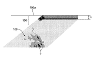
- the generation direction of the defect is different from the irradiation direction of the ultrasonic wave, the direction of the reflected wave is different. For example, referring to FIG.
- the phased array probe 100 when the irradiation direction of the ultrasonic wave u from the phased array probe 100 is perpendicular to the generation direction of the crack c, the phased array probe 100 reliably reflects the reflected wave e. I can receive it. On the other hand, even if there is a defect at the same position, if the irradiation direction of the ultrasonic wave deviates from the right angle to the crack generation direction, the reflectance of the reflected wave in the receiving direction decreases and the reflected wave can not be detected. There is a case. As a result, the defect detection accuracy is reduced.
- phased array probe 100 is disposed on the end surface 106 a of the rotor disk 106.
- the plurality of transducers 110 are arranged along the radial direction a of the rotor disk 106.
- the phased array probe 100 transmits ultrasonic waves u toward the wing groove portion 108, and a reflected wave from the wing groove portion 108 Receive
- the phased array probe 100 transmits ultrasonic waves u toward the wing groove portion 108, and a reflected wave from the wing groove portion 108 Receive
- At least one embodiment of the present invention aims to provide a method and an apparatus for ultrasonic flaw detection on a blade groove of a turbine rotor disk capable of detecting a defect such as a crack with high accuracy.
- a method of ultrasonic flaw detection of a blade groove of a turbine rotor disk An arranging step of arranging a phased array probe including a plurality of transducers capable of transmitting ultrasonic waves on the end face of the rotor disk in a parallel state in which the plurality of transducers are arranged along the circumferential direction of the rotor disk
- Ultrasonic waves are transmitted from the plurality of transducers in the parallel state in a state in which the ultrasonic wave transmission timing of each of the plurality of transducers is controlled by a first transmission pattern, and a reflected wave of the ultrasonic waves is received
- Ultrasonic waves are emitted from the plurality of transducers in the parallel state in a state in which the ultrasound transmission timing of each of the plurality of transducers is controlled by a second transmission pattern different from the first transmission pattern,
- a second transmitting and receiving step of receiving the reflected wave of the ultrasonic wave Equipped with
- the present inventors use a phased array probe 100 in which a large number of transducers 110 are juxtaposed along the radial direction (direction of arrow a) of the rotor disk end face 106a.
- the proportion of the reflected wave e received by the phased array probe 100 decreases depending on the direction of the sound wave irradiation, and it has been found that defects can not be inspected with high accuracy. And it turned out that this phenomenon becomes remarkable especially when a curved side entry type wing groove part is inspected.
- a plurality of transducers are arranged in parallel along the circumferential direction of the end face of the rotor disk, and ultrasonic waves are transmitted by the first transmission pattern and the second transmission pattern.
- the irradiation direction of the ultrasonic wave can be easily changed in the circumferential direction of the end face of the rotor disk without changing the direction of the phased array probe.
- defects such as cracks which can not be detected in the first transmission pattern can be detected in the second transmission pattern And vice versa.
- along the X direction it means that the case where the direction slightly deviates from the X direction is included is also included in the strict sense other than the case along the X direction.
- Each of the plurality of transducers has a transmitting surface capable of transmitting an ultrasonic wave,
- the transmission surface is longer in a direction intersecting with the arrangement direction than the arrangement direction of the plurality of transducers, and the arrangement direction and the ultrasonic waves emitted from the transmission surface converge on one focal point. It has a concave shape in which the central portion is recessed in the intersecting direction. According to the above configuration (2), since the ultrasonic waves transmitted from the transmission surface converge on one focal point, it is possible to increase the detection accuracy of the defect present in the vicinity of the focal point.
- the method further comprises a radial movement step of moving the probe along a radial direction of the rotor disk, Before and after the radial movement step, the first transmission and reception step and the second transmission and reception step are performed.
- the phased array probe can be in a wide range without changing the direction. The defect can be easily inspected with high accuracy.
- the method further includes an adjusting step of adjusting the number of the plurality of transducers included in the phased array probe according to the size or the shape of the wing groove.
- the phased array probe can be miniaturized by adjusting the number of transducers in accordance with the size and shape of the rotor disk and the blade groove. Therefore, even a turbine rotor with a small gap between the rotor disks and a small gap between the blade grooves can be easily inspected with high accuracy.
- each of the plurality of transducers can receive a reflected wave of the ultrasonic wave.
- the transducer serves as the transducer for ultrasonic wave transmission and the transducer for ultrasonic wave reception, defects can be inspected easily with high accuracy with a simple configuration. .
- any one of the above configurations (1) to (4) It further comprises a plurality of receiving transducers for receiving the reflected waves of the ultrasonic waves.
- the transducer for transmitting the ultrasonic wave and the transducer for receiving are separately provided, the ultrasonic wave transmitted from the transducer in the vicinity of the end face of the rotor disk (incident wave Interference with the reflected wave) can be suppressed. As a result, defects can be easily inspected with high accuracy even in a region closer to the surface of the end surface of the rotor disk.
- a blade groove portion for fixing a turbine blade provided on a rotor disk of the turbine extends in an arc shape deviated from the axial direction of the rotor disk.
- the defect is easily inspected with high accuracy by changing the irradiation direction of the ultrasonic wave.
- An ultrasonic wave flaw detection method for a turbine rotor disk according to at least one embodiment of the present invention which is used for the ultrasonic flaw detection method for a blade groove part of a turbine rotor disk according to one of (1) to (7)
- the ultrasonic flaw detector is The phased array probe including the plurality of transducers;
- the phased array probe is configured to support the plurality of transducers arranged in the radial direction of the rotor disk, and the phased array probe is arranged along the circumferential direction of the rotor disk.
- a probe support device configured to movably support; Equipped with
- the phased array probe can be easily moved along the radial direction of the rotor disk by the probe support device. Therefore, the defect can be inspected with high accuracy and easily for a wide range of one blade groove.
- the apparatus further comprises a rotor disk support device rotatably supporting the rotor disk,
- the probe support device A dolly capable of traveling in one traveling direction, An expandable post mounted on the carriage;
- An extendable arm rotatably supported in a vertical plane including the traveling direction by the support;
- the phased array probe is supported by the carriage via the arm and a post.
- the phased array probe can be easily positioned at any position on the end face of the rotor disk by rotation of the rotor disk, movement of the carriage, extension and contraction of the support, extension and contraction of the arm, and rotation of the arm. It can be arranged. For this reason, defects can be inspected with high accuracy and easily for a wide range of blade grooves.
- phased array probe in the above configuration (9), A frame provided between the phased array probe and the tip of the arm and rotatably supporting the phased array probe; An elastic member provided between the frame and the phased array probe for pressing the phased array probe toward the end face of the rotor disk.
- the phased array probe by pressing the phased array probe toward the end face of the rotor disk by the elastic member, the phased array probe can always be kept in close contact with the end face, so that the inspection can be performed with high accuracy. It can be done easily and stably.
- an ultrasonic flaw detection method and apparatus for a blade groove of a turbine rotor disk capable of detecting defects such as cracks with high accuracy are provided.
- FIG. 1 is a front view schematically showing an ultrasonic flaw detector according to an embodiment of the present invention together with a part of a rotor disk. It is an explanatory view showing a flaw detection method in the embodiment. It is a schematic diagram which shows the phased array probe of the said ultrasonic flaw detector.
- FIG. 4 is a schematic view seen from the direction B in FIG. 3 according to another embodiment of the present invention.
- FIG. 6 is a schematic view of a phased array probe according to yet another embodiment of the present invention.
- FIG. 6 is a schematic view of a phased array probe according to yet another embodiment of the present invention. It is C arrow line view in FIG.
- FIG. 1 It is a schematic diagram which shows generation
- (A) to (D) are explanatory views showing various scanning methods using a phased array probe. It is a perspective view showing a curved side entry type wing groove part. It is explanatory drawing which shows the inspection method by the conventional phased array method.
- expressions that indicate that things such as “identical”, “equal” and “homogeneous” are equal states not only represent strictly equal states, but also have tolerances or differences with which the same function can be obtained. It also represents the existing state.
- expressions representing shapes such as quadrilateral shapes and cylindrical shapes not only represent shapes such as rectangular shapes and cylindrical shapes in a geometrically strict sense, but also uneven portions and chamfers within the range where the same effect can be obtained. The shape including a part etc. shall also be expressed.
- the expressions “comprising”, “having”, “having”, “including” or “having” one component are not exclusive expressions excluding the presence of other components.
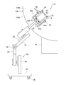
- FIG. 1 shows the configuration of an ultrasonic flaw detector 10 according to the present embodiment.
- the phased array probe 12 has a rectangular parallelepiped outer shape, is accommodated in a space formed inside the rectangular frame 14, and is fixed to the frame 14 by a fixing means such as a bolt in that state.
- the frame 14 has a pivot shaft 14a formed integrally.
- the frame 14 is inserted into the inside of a rectangular support frame 16 whose one side is open, and the pivot shaft 14 a is rotatably fitted in a hole formed in the support frame 16.
- the frame 14 is rotatably supported by the support frame 16 about the pivot shaft 14 a.
- Two springs 18 are provided on the bottom of the support frame 16 facing the frame 14.
- the spring 18 adheres the phased array probe 12 to the rotor disk end face 106 a when the frame 14 is in one direction about the pivot shaft 14 a, that is, when the phased array probe 12 is disposed on the rotor disk end face 106 a
- a spring force is applied to turn it in the direction of rotation.
- illustration of the turbine blade and the blade groove portion mounted on the outer peripheral surface 106 b of the rotor disk 106 is omitted.
- the support frame 20 is configured of a rectangular support frame 20a whose one side is open and a main shaft 20b coupled to the support frame 20a.
- the support frame 16 is fixed to the support frame 20 a by bolts 22.
- the frame body 14 and the support frame 16 each have four balls 24 at four corners on one side (the surface facing the rotor disk end surface 106 a).
- the ball 24 is rotatably mounted on the frame 14 or the support frame 16. The balls 24 allow the frame 14 and the support frame 16 to slide easily in contact with the end face 106 a of the rotor disk 106.
- the probe support device 26 has four wheels 36 and is vertically movable including the traveling direction by the carriage 34 capable of traveling in one traveling direction, the support 38 mounted on the carriage 34 and fixed thereto, and the support 38 And an arm 31 rotatably supported in the plane.
- the column 38 has a height adjustment portion 28, and the height adjustment portion 28 is slidably supported in the height direction with respect to the column 38.
- the arm 31 is rotatably supported in one plane with respect to the height adjustment unit 28 via the shaft 30.
- the arm 31 has a scanning position adjustment unit 32, and the scanning position adjustment unit 32 slidably supports the main shaft 20b of the support frame 20 in the axial direction of the main shaft 20b in the plane.
- the ultrasonic flaw detection apparatus 10 can position the phased array probe 12 at an arbitrary position on the rotor disk end surface 106 a when the plane is placed parallel to the rotor disk end surface 106 a.
- phased array probe 12 on the side of transmitting ultrasonic waves is fixed to the frame 14 so as to have substantially the same height as the frame 14 and the support frame 16.
- a cable 40 is connected to the phased array probe 12.
- a control signal is input to the phased array probe 12 via the cable 40, and a detection signal is output from the phased array probe 12.
- the inspection target of the ultrasonic flaw detection apparatus 10 is, for example, a curved side entry type wing groove portion 108 shown in FIG.
- the ultrasonic testing device 10 is moved to the rotor disk 106, and the phased array probe 12 is placed on the rotor disk end surface 106a.
- the shaft 30 so as to be orthogonal to the rotor disk end face 106a, the plane on which the arm 31 pivots can be made parallel to the rotor disk end face 106a.
- the feeler 12 can be moved in the radial direction of the rotor disk 106.
- the rotor disk 106 is rotatably supported by the rotor disk support device 39, and a radial movement process of moving the phased array probe 12 along the radial direction of the rotor disk 106 is performed.
- ultrasonic waves are emitted from the phased array probe 12 toward the wing groove portion 108 in a state of being disposed on the rotor disk end face 106 a, and the reflected wave reflected by the wing groove portion 108 is received by the phased array probe 12.
- the turbine rotor is turned manually or by a drive motor, and another radial movement step is performed. By repeating this, ultrasonic waves can be applied to all the blade grooves 108 mounted on the entire circumference of the rotor disk outer peripheral surface 106b, and all the blade grooves 108 can be inspected.
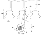
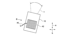
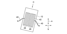
- FIG. 2 is a view showing an ultrasonic wave transmission region of the ultrasonic flaw detection apparatus 10, and FIG. 3 is an enlarged view showing the phased array probe 12.
- the phased array probe 12 has a large number of transducers 42.
- the vibrator 42 has a rod shape having a square cross section, and is arranged side by side in the circumferential direction (arrow b direction) of the rotor disk 106.
- the cable 40 sends an electric pulse to the vibrator 42 to excite the vibrator 42. Further, when the ultrasonic wave emitted by the vibrator 42 is reflected by the blade groove portion 108 and the reflected wave is received by the vibrator 42, the cable 40 sends the received reflected wave to a processing unit (not shown).
- the blade groove 108 is irradiated with ultrasonic waves from the phased array probe 12 at a skew angle A.
- the angle of the ultrasonic wave irradiation direction or the front-rear direction of the phased array probe 100 with respect to the radial direction a of the rotor disk 106 is defined as a skew angle A.
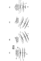
- FIGS. 9A to 9D schematically explain various scanning methods by the phased array method.
- the phased array probe 12 has a large number of transducers 42 arranged in parallel, and by controlling the timing of the pulse voltage applied to each transducer 42, the excitation time for each transducer 42 is controlled, Sound wave transmission timing (transmission pattern) can be controlled.
- Sound wave transmission timing transmission pattern
- the focal length connecting f2 can be freely changed.
- the excitation timings of the respective transducers 42 are controlled so as to enable, for example, the scans shown in FIGS. 9B and 9C.
- the transmission pattern shown in FIG. 9 (B) is adopted in the first transmission / reception step
- the transmission pattern shown in FIG. 9 (C) is adopted in the second transmission / reception step.
- the irradiation direction of the ultrasonic wave transmitted from each transducer 42 can be changed not only in the direction defined by the skew angle A but also in the circumferential direction b of the rotor disk 106. Therefore, the scanning range t of the ultrasonic wave can be widely expanded in a fan shape.
- the transmission pattern is not limited to the first transmission pattern and the second transmission pattern.
- the scanning range t can be finely analyzed by electrically and continuously scanning the irradiation direction of ultrasonic waves by employing a large number of transmission patterns.
- a plurality of transducers 42 are arranged in parallel along the circumferential direction b of the rotor disk end face 106a, and ultrasonic waves are transmitted by the first transmission pattern and the second transmission pattern.
- the irradiation direction of the ultrasonic wave can be easily changed in the circumferential direction b of the rotor disk end face 106a.
- a defect such as a crack which can not be detected in the first transmission pattern is detected in the second transmission pattern.
- defects can be enhanced over a wide range without changing the direction of the phased array probe 12 It can be easily inspected with accuracy.
- the transducer 42 serves as the transducer for ultrasonic wave transmission and the transducer for ultrasonic wave reception, defects can be easily inspected with high accuracy with a simple configuration.
- the ultrasonic flaw detection apparatus 10 has a rotor disk support device 39 so that the phased array probe 12 can be easily moved along the radial direction of the rotor disk 106. Therefore, defects can be inspected with high accuracy and easily for a wide range of one blade groove portion 108.
- phased array probe 12 can be easily disposed at any position on the rotor disk end face 106 a by the rotation of the rotor disk 106, the movement of the carriage 34, the extension and contraction of the support 38, and the extension and contraction of the arm 31. can do. For this reason, defects can be inspected with high accuracy and easily for a wide range of blade grooves 108.
- phased array probe 12 can be closely attached to the rotor disk end face 106 a by the elastic force of the spring 18, the defect detection accuracy can be further improved.
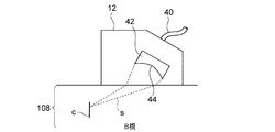
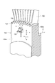
- FIG. 4 is a view of the vibrator 42 according to some embodiments as viewed from the B direction in FIG. 3.
- the ultrasound transmission surface 44 of each transducer 42 is longer in the direction intersecting with the alignment direction than the alignment direction of the transducers 42, and the ultrasound transmitted from the ultrasound transmission surface 44 Has a concave shape in which a central portion is recessed with respect to the blade groove portion 108 in a direction intersecting with the arrangement direction so that L converges to one focal point.
- the detection accuracy of the defect existing in the vicinity of the focal point can be increased. it can.
- each transducer 42 in the phased array probe 12, the longitudinal direction of each transducer 42 is inclined with respect to the rotor disk end surface 106a so that the ultrasonic wave obliquely enters the rotor disk end surface 106a.
- the respective transducers 42 are arranged in
- FIG. 5 schematically shows a phased array probe 12 according to another embodiment of the invention applied to a small turbine rotor.
- the phased array probe 12 is also miniaturized, and the number of transducers 42 is halved as compared with the embodiment.
- the number of transducers 42 in the embodiment is 32, 16 transducers 42 are disposed in the present embodiment.
- the phased array probe 12 can be miniaturized by adjusting the number of transducers 42 in accordance with the size and shape of the rotor disk 106 and the blade groove 108. Therefore, even a turbine rotor with a small gap between the rotor disks and a small gap between the blade grooves can be easily inspected with high accuracy.
- the ultrasonic wave transmitting unit 46 and the ultrasonic wave receiving unit 48 each configured of the vibrator 42 are separately configured.
- the ultrasound transmission unit 46 and the ultrasound reception unit 48 are disposed at different positions inside the phased array probe 12.
- the transmitting surface of the ultrasonic wave transmitting unit 46 and the receiving surface of the ultrasonic wave receiving unit 48 are inclined in the direction to face each other.
- the ultrasonic wave transmitter 46 transmits the ultrasonic wave u toward the blade groove 108, the reflected wave e reflected from the blade groove 108 is received by the ultrasonic wave receiver 48, and the waveform of the reflected wave e is examined to obtain defects.
- To detect the presence or size of The other configuration is the same as that of the above embodiment.
- the ultrasonic wave transmitting unit 46 and the ultrasonic wave receiving unit 48 are constituted by the same vibrator, the incident wave and the reflected wave interfere with each other to face the surface of the rotor disk end face 106a.
- Dead band n is expressed.
- the ultrasonic wave transmitting unit 46 and the ultrasonic wave receiving unit 48 by separately providing the ultrasonic wave transmitting unit 46 and the ultrasonic wave receiving unit 48, interference between the ultrasonic wave (incident wave) transmitted by the vibrator 42 and the reflected wave is generated near the rotor disk end face 106a. It can be suppressed. As a result, the dead zone n developed on the surface of the rotor disk end face 106a can be reduced, and a defect can be easily inspected with high precision even in a region closer to the surface of the rotor disk end face 106a.
- the ultrasound transmission unit 46 and the ultrasound reception unit 48 are arranged in the width direction of the phased array probe 12, and a plurality of transducers of the ultrasound transmission unit 46, and ultrasound reception The section 48 is also aligned in the width direction of the phased array probe 12.
- the transmitting surfaces of the plurality of transducers of the ultrasonic transmitting unit 46 and the receiving surfaces of the transducers of the ultrasonic receiving unit 48 are inclined with respect to the end face of the rotor disk, specifically, the transmitting surface Are inclined so that the normal of the vibrator and the normal of the vibrator intersect at the rotor disk side.
- the present invention is not limited to the above-described embodiments, and includes the embodiments in which the above-described embodiments are modified, and the embodiments in which these embodiments are appropriately combined.
- a defect such as a crack can be easily inspected with high accuracy for a blade groove portion for fixing a turbine moving blade provided on a rotor disk of a turbine.
Abstract
Selon la présente invention, les étapes suivantes sont comprises : une étape d'alignement dans laquelle une sonde à réseau à commande de phase qui contient une pluralité de transducteurs qui sont chacun capables d'émettre des ultrasons et alignés contre une surface d'extrémité du disque de rotor de sorte que la pluralité de transducteurs soient dans un état parallèle, alignés dans la direction circonférentielle du disque de rotor; une première étape d'émission/réception dans laquelle des ultrasons sont émis depuis la pluralité de transducteurs dans l'état parallèle mentionné ci-dessus, la temporisation de l'émission d'ultrasons depuis les transducteurs respectifs étant contrôlée conformément à un premier profil d'émission et les ultrasons réfléchis résultants sont reçus; et une deuxième étape d'émission/réception dans laquelle des ultrasons sont émis depuis la pluralité de transducteurs dans l'état parallèle mentionné ci-dessus, la temporisation de l'émission d'ultrasons depuis les transducteurs respectifs étant contrôlée conformément à un deuxième profil d'émission qui est différent du premier profil d'émission mentionné ci-dessus et les ultrasons réfléchis résultants sont reçus.
Priority Applications (3)
| Application Number | Priority Date | Filing Date | Title |
|---|---|---|---|
| US15/502,693 US10845341B2 (en) | 2014-08-12 | 2015-07-28 | Ultrasonic flaw-detection method and apparatus for blade groove in turbine rotor disc |
| EP15831648.9A EP3182116A4 (fr) | 2014-08-12 | 2015-07-28 | Procédé de détection de défaut ultrasonore et dispositif pour rainure de pale dans un disque de retour de turbine |
| CN201580034325.4A CN106662553A (zh) | 2014-08-12 | 2015-07-28 | 涡轮转子盘的叶片槽部的超声波探伤方法以及装置 |
Applications Claiming Priority (2)
| Application Number | Priority Date | Filing Date | Title |
|---|---|---|---|
| JP2014-164455 | 2014-08-12 | ||
| JP2014164455A JP6395498B2 (ja) | 2014-08-12 | 2014-08-12 | タービンロータディスクの翼溝部の超音波探傷方法及び装置 |
Publications (1)
| Publication Number | Publication Date |
|---|---|
| WO2016024475A1 true WO2016024475A1 (fr) | 2016-02-18 |
Family
ID=55304104
Family Applications (1)
| Application Number | Title | Priority Date | Filing Date |
|---|---|---|---|
| PCT/JP2015/071383 WO2016024475A1 (fr) | 2014-08-12 | 2015-07-28 | Procédé de détection de défaut ultrasonore et dispositif pour rainure de pale dans un disque de retour de turbine |
Country Status (5)
| Country | Link |
|---|---|
| US (1) | US10845341B2 (fr) |
| EP (1) | EP3182116A4 (fr) |
| JP (1) | JP6395498B2 (fr) |
| CN (1) | CN106662553A (fr) |
| WO (1) | WO2016024475A1 (fr) |
Families Citing this family (9)
| Publication number | Priority date | Publication date | Assignee | Title |
|---|---|---|---|---|
| KR101645976B1 (ko) * | 2016-04-12 | 2016-08-05 | 주식회사 에네스지 | 터빈 로터의 도브테일부 검사용 다관절 초음파 검사장치 |
| JP6731774B2 (ja) * | 2016-04-15 | 2020-07-29 | 三菱日立パワーシステムズ株式会社 | 超音波探傷装置 |
| KR101809607B1 (ko) | 2016-07-26 | 2017-12-18 | 고려공업검사 주식회사 | 터빈 로터 핑거 도브테일용 비파괴검사장치 |
| KR101919233B1 (ko) | 2017-04-27 | 2019-02-08 | 두산중공업 주식회사 | 로터 검사장치 및 검사방법 |
| JP7051433B2 (ja) * | 2017-12-28 | 2022-04-11 | 三菱重工コンプレッサ株式会社 | 回転機械の余寿命評価方法、回転機械の余寿命評価システム、及び回転機械の余寿命評価プログラム |
| JP6896170B2 (ja) * | 2018-05-25 | 2021-06-30 | 三菱電機株式会社 | ロータティースクラック検査方法 |
| KR102085689B1 (ko) * | 2018-08-09 | 2020-04-23 | 주식회사 파워인스 | 퍼트리형 터빈 블레이드 루트 초음파검사용 센서이송장치 |
| JP7391537B2 (ja) * | 2019-05-20 | 2023-12-05 | 三菱重工業株式会社 | 超音波検査装置 |
| CN110794034B (zh) * | 2019-11-19 | 2023-07-11 | 中广核核电运营有限公司 | 核电站低压缸红套转子汽轮机叶片叶根超声相控阵全自动检测方法 |
Citations (9)
| Publication number | Priority date | Publication date | Assignee | Title |
|---|---|---|---|---|
| JPH0619341B2 (ja) * | 1985-11-11 | 1994-03-16 | 株式会社東芝 | 電子走査型超音波探傷装置 |
| JP2004340809A (ja) * | 2003-05-16 | 2004-12-02 | Mitsubishi Heavy Ind Ltd | フェーズドアレイプローブ及びそれを用いた超音波探傷装置 |
| JP2007116894A (ja) * | 2005-10-20 | 2007-05-10 | General Electric Co <Ge> | 発電機ロータ歯検査用のフェーズドアレイ超音波方法およびシステム |
| JP2007278854A (ja) * | 2006-04-07 | 2007-10-25 | Hitachi Ltd | 超音波検査方法及び装置 |
| JP2007309771A (ja) * | 2006-05-18 | 2007-11-29 | Hitachi Ltd | 超音波探傷方法及び超音波探傷装置 |
| WO2009000793A1 (fr) * | 2007-06-26 | 2008-12-31 | Alstom Technology Ltd | Procédé d'inspection non destructive de pales de rotor d'une turbine à vapeur et dispositif d'inspection à utiliser pour ledit procédé |
| JP2009244079A (ja) * | 2008-03-31 | 2009-10-22 | Tokyo Electric Power Co Inc:The | タービン翼植込部超音波探傷装置および探傷方法 |
| JP2010185367A (ja) * | 2009-02-12 | 2010-08-26 | Mitsubishi Heavy Industries Compressor Corp | タービン動翼の固定構造及びタービン |
| JP2011027423A (ja) * | 2009-07-21 | 2011-02-10 | Toshiba Corp | 超音波探傷試験方法 |
Family Cites Families (26)
| Publication number | Priority date | Publication date | Assignee | Title |
|---|---|---|---|---|
| US1719415A (en) * | 1927-09-14 | 1929-07-02 | Westinghouse Electric & Mfg Co | Turbine-blade attachment |
| US3986793A (en) * | 1974-10-29 | 1976-10-19 | Westinghouse Electric Corporation | Turbine rotating blade |
| US4502331A (en) * | 1983-09-14 | 1985-03-05 | Southwest Research Institute | Method for ultrasonic inspection of turbine disc rims |
| US4767275A (en) * | 1986-07-11 | 1988-08-30 | Westinghouse Electric Corp. | Locking pin system for turbine curved root side entry closing blades |
| JPH01299456A (ja) * | 1988-05-27 | 1989-12-04 | Toshiba Corp | 超音波探傷装置 |
| JP2966515B2 (ja) * | 1990-11-28 | 1999-10-25 | 株式会社日立製作所 | 超音波検査方法及び超音波検査装置 |
| JPH05244691A (ja) | 1992-02-27 | 1993-09-21 | Hitachi Ltd | 超音波探触子 |
| JP3128196B2 (ja) * | 1996-01-08 | 2001-01-29 | 三菱重工業株式会社 | タービンブレード用超音波探傷装置 |
| JP3390748B2 (ja) * | 2001-04-16 | 2003-03-31 | 株式会社四国総合研究所 | タービンロータ翼植込部超音波探傷装置及び該装置を用いた探傷方法 |
| US6792809B1 (en) * | 2003-05-02 | 2004-09-21 | Siemens Westinghouse Power Corporation | Self-aligning turbine disc inspection apparatus |
| US7174788B2 (en) * | 2003-12-15 | 2007-02-13 | General Electric Company | Methods and apparatus for rotary machinery inspection |
| JP2007151561A (ja) | 2004-10-15 | 2007-06-21 | Olympus Corp | 超音波探触子 |
| JP2006194591A (ja) * | 2005-01-11 | 2006-07-27 | Mitsubishi Heavy Ind Ltd | 超音波探傷装置 |
| US7428842B2 (en) * | 2005-06-20 | 2008-09-30 | Siemens Power Generation, Inc. | Phased array ultrasonic testing system and methods of examination and modeling employing the same |
| JP2007322350A (ja) | 2006-06-05 | 2007-12-13 | Tokyo Electric Power Co Inc:The | 超音波探傷装置及び方法 |
| JP4474395B2 (ja) * | 2006-09-29 | 2010-06-02 | 株式会社日立製作所 | タービンフォーク超音波探傷装置及び方法 |
| US7654143B2 (en) * | 2007-04-03 | 2010-02-02 | General Electric Company | Method and apparatus for in-situ inspection of rotary machine components |
| JP2009204368A (ja) * | 2008-02-26 | 2009-09-10 | Mitsubishi Heavy Ind Ltd | タービンロータ翼溝検査方法 |
| JP5112261B2 (ja) * | 2008-11-12 | 2013-01-09 | 三菱重工業株式会社 | フェイズドアレイ探触子及びその仕様決定方法 |
| JP4961051B2 (ja) * | 2009-05-28 | 2012-06-27 | 一般財団法人電力中央研究所 | 非破壊検査用走査装置および非破壊検査装置 |
| US8525831B2 (en) * | 2009-10-05 | 2013-09-03 | Siemens Corporation | Method and apparatus for three-dimensional visualization and analysis for automatic non-destructive examination of a solid rotor using ultrasonic phased array |
| JP2011208978A (ja) * | 2010-03-29 | 2011-10-20 | Hitachi Ltd | タービン翼植込み部の超音波検査方法および装置 |
| GB2480633B (en) * | 2010-05-26 | 2013-12-25 | Phoenix Inspection Systems Ltd | Inspection apparatus and method |
| JP2012253583A (ja) | 2011-06-03 | 2012-12-20 | Hitachi Consumer Electronics Co Ltd | 配信装置 |
| JP5730164B2 (ja) * | 2011-09-14 | 2015-06-03 | 三菱重工業株式会社 | ロータディスクの翼溝部の探傷装置 |
| JP5383892B2 (ja) | 2012-11-19 | 2014-01-08 | 三菱重工業株式会社 | タービン用ロータディスクの超音波探傷装置 |
-
2014
- 2014-08-12 JP JP2014164455A patent/JP6395498B2/ja active Active
-
2015
- 2015-07-28 US US15/502,693 patent/US10845341B2/en active Active
- 2015-07-28 EP EP15831648.9A patent/EP3182116A4/fr not_active Withdrawn
- 2015-07-28 WO PCT/JP2015/071383 patent/WO2016024475A1/fr active Application Filing
- 2015-07-28 CN CN201580034325.4A patent/CN106662553A/zh active Pending
Patent Citations (9)
| Publication number | Priority date | Publication date | Assignee | Title |
|---|---|---|---|---|
| JPH0619341B2 (ja) * | 1985-11-11 | 1994-03-16 | 株式会社東芝 | 電子走査型超音波探傷装置 |
| JP2004340809A (ja) * | 2003-05-16 | 2004-12-02 | Mitsubishi Heavy Ind Ltd | フェーズドアレイプローブ及びそれを用いた超音波探傷装置 |
| JP2007116894A (ja) * | 2005-10-20 | 2007-05-10 | General Electric Co <Ge> | 発電機ロータ歯検査用のフェーズドアレイ超音波方法およびシステム |
| JP2007278854A (ja) * | 2006-04-07 | 2007-10-25 | Hitachi Ltd | 超音波検査方法及び装置 |
| JP2007309771A (ja) * | 2006-05-18 | 2007-11-29 | Hitachi Ltd | 超音波探傷方法及び超音波探傷装置 |
| WO2009000793A1 (fr) * | 2007-06-26 | 2008-12-31 | Alstom Technology Ltd | Procédé d'inspection non destructive de pales de rotor d'une turbine à vapeur et dispositif d'inspection à utiliser pour ledit procédé |
| JP2009244079A (ja) * | 2008-03-31 | 2009-10-22 | Tokyo Electric Power Co Inc:The | タービン翼植込部超音波探傷装置および探傷方法 |
| JP2010185367A (ja) * | 2009-02-12 | 2010-08-26 | Mitsubishi Heavy Industries Compressor Corp | タービン動翼の固定構造及びタービン |
| JP2011027423A (ja) * | 2009-07-21 | 2011-02-10 | Toshiba Corp | 超音波探傷試験方法 |
Non-Patent Citations (1)
| Title |
|---|
| See also references of EP3182116A4 * |
Also Published As
| Publication number | Publication date |
|---|---|
| US10845341B2 (en) | 2020-11-24 |
| CN106662553A (zh) | 2017-05-10 |
| JP2016040529A (ja) | 2016-03-24 |
| US20170254785A1 (en) | 2017-09-07 |
| EP3182116A1 (fr) | 2017-06-21 |
| JP6395498B2 (ja) | 2018-09-26 |
| EP3182116A4 (fr) | 2018-02-21 |
Similar Documents
| Publication | Publication Date | Title |
|---|---|---|
| WO2016024475A1 (fr) | Procédé de détection de défaut ultrasonore et dispositif pour rainure de pale dans un disque de retour de turbine | |
| US8402830B2 (en) | Method for the non-destructive testing of a test object by way of ultrasound and apparatus therefor | |
| Rajagopalan et al. | A single transmitter multi-receiver (STMR) PZT array for guided ultrasonic wave based structural health monitoring of large isotropic plate structures | |
| JP4092704B2 (ja) | 超音波試験方法及びこれを用いた超音波試験装置 | |
| JP2005315892A5 (fr) | ||
| KR20100021463A (ko) | 초음파를 이용한 검사 물체의 비파괴 재료 검사를 위한 방법 및 장치 | |
| US9279786B2 (en) | Method of and an apparatus conducting calibration for phased-array shear wave channels inspecting square bars | |
| US10197535B2 (en) | Apparatus and method for full-field pulse-echo laser ultrasonic propagation imaging | |
| CN104634880B (zh) | 超声波探伤传感器以及超声波探伤方法 | |
| JP2009186446A (ja) | タービンロータ翼溝部の探傷方法及び装置 | |
| US9213019B2 (en) | Method of determining a size of a defect using an ultrasonic linear phased array | |
| JP6594608B2 (ja) | 超音波検出方法及び超音波分析方法 | |
| EP3320334B1 (fr) | Procédé et dispositif pour l'inspection d'une roue de chemin de fer avec des réseaux en phase | |
| KR20220034889A (ko) | 초음파 검사 시스템 및 초음파 검사 방법 | |
| EP3044581B1 (fr) | Échographe tournant à réseau de traducteurs courbé | |
| JP6298371B2 (ja) | 超音波探傷装置及び超音波探傷方法 | |
| JP2020030070A (ja) | 超音波探傷方法及び探傷装置 | |
| JP6842084B2 (ja) | 携帯型3軸応力測定装置 | |
| JP6081028B1 (ja) | 超音波測定装置 | |
| JP5345096B2 (ja) | アレイ超音波探傷装置 | |
| JP2019078558A (ja) | 対比試験片及び超音波フェーズドアレイ探傷試験方法 | |
| JP5959677B2 (ja) | 超音波探傷装置および超音波探傷方法 | |
| EP3739330A1 (fr) | Essai de roue de rail à grande vitesse en service | |
| Devos et al. | Optimized semi-flexible matrix array probes for large rotor shafts and DGS sizing diagram simulation tool | |
| JP2018136175A (ja) | 超音波探傷装置及び超音波探傷方法 |
Legal Events
| Date | Code | Title | Description |
|---|---|---|---|
| 121 | Ep: the epo has been informed by wipo that ep was designated in this application |
Ref document number: 15831648 Country of ref document: EP Kind code of ref document: A1 |
|
| REEP | Request for entry into the european phase |
Ref document number: 2015831648 Country of ref document: EP |
|
| WWE | Wipo information: entry into national phase |
Ref document number: 2015831648 Country of ref document: EP |
|
| WWE | Wipo information: entry into national phase |
Ref document number: 15502693 Country of ref document: US |
|
| NENP | Non-entry into the national phase |
Ref country code: DE |