WO2016017827A1 - ポット型ナノカーボン材料及びその製造方法 - Google Patents
ポット型ナノカーボン材料及びその製造方法 Download PDFInfo
- Publication number
- WO2016017827A1 WO2016017827A1 PCT/JP2015/072436 JP2015072436W WO2016017827A1 WO 2016017827 A1 WO2016017827 A1 WO 2016017827A1 JP 2015072436 W JP2015072436 W JP 2015072436W WO 2016017827 A1 WO2016017827 A1 WO 2016017827A1
- Authority
- WO
- WIPO (PCT)
- Prior art keywords
- catalyst
- reaction chamber
- substrate
- carbon
- diameter
- Prior art date
- Legal status (The legal status is an assumption and is not a legal conclusion. Google has not performed a legal analysis and makes no representation as to the accuracy of the status listed.)
- Ceased
Links
Images







Classifications
-
- B—PERFORMING OPERATIONS; TRANSPORTING
- B01—PHYSICAL OR CHEMICAL PROCESSES OR APPARATUS IN GENERAL
- B01J—CHEMICAL OR PHYSICAL PROCESSES, e.g. CATALYSIS OR COLLOID CHEMISTRY; THEIR RELEVANT APPARATUS
- B01J23/00—Catalysts comprising metals or metal oxides or hydroxides, not provided for in group B01J21/00
- B01J23/70—Catalysts comprising metals or metal oxides or hydroxides, not provided for in group B01J21/00 of the iron group metals or copper
- B01J23/74—Iron group metals
- B01J23/75—Cobalt
-
- C—CHEMISTRY; METALLURGY
- C01—INORGANIC CHEMISTRY
- C01B—NON-METALLIC ELEMENTS; COMPOUNDS THEREOF; METALLOIDS OR COMPOUNDS THEREOF NOT COVERED BY SUBCLASS C01C
- C01B32/00—Carbon; Compounds thereof
- C01B32/05—Preparation or purification of carbon not covered by groups C01B32/15, C01B32/20, C01B32/25, C01B32/30
Definitions
- the present invention relates to a novel nanocarbon material and a method for producing the same, and more particularly, to a pot-type nanocarbon material having regions in which the growth of graphene nanosheets is different and a method for producing the same.
- Carbon nanotubes have unique electronic properties, adsorption properties, and mechanical properties, for example, scanning probe microscope (SPM) probes, field emission display (FED) emitters, fuel cell hydrogen storage materials, lithium
- SPM scanning probe microscope
- FED field emission display
- fuel cell hydrogen storage materials lithium
- CNT Carbon Nano Tubes
- CVD chemical vapor deposition method
- the arc discharge method and the laser evaporation method can obtain high-quality or high-purity carbon nanotubes, but have a low yield and are difficult to industrially mass-produce.
- the CVD method is suitable for mass synthesis because a carbon compound serving as a carbon source can be supplied as a raw material gas, but is inferior in crystallinity of carbon nanotubes.
- Patent Document 1 A method of synthesizing CNTs by depositing a metal catalyst on a substrate and heating the substrate in an organic liquid (Patent Document 1, Non-Patent Documents 1 and 2) has also been proposed, but the substrate is immersed in the organic liquid. Then, CNT is synthesized with the metal catalyst in direct contact with the organic liquid (submerged substrate heating method), so the catalyst on the substrate reacts with the organic liquid before the substrate reaches the optimum synthesis temperature of CNT. Therefore, it was impossible to obtain carbon nanotubes with high purity in a stable manner. As for the catalyst, the catalyst material eluted in the organic liquid cannot be used because it is peeled off from the substrate when the carbon nanotube is synthesized.
- the present inventor has stored the organic liquid in a tank body whose interior is closed, uses the remaining volume space as a reaction space, generates a synthesis condition by heating the catalyst-carrying substrate, and converts the organic liquid evaporative gas into the carbon source gas.
- Proposed a submarine substrate heating method in which a nanocarbon material is vapor-phase grown on a catalyst Patent Document 3).
- Non-Patent Document 2 As a nanocarbon material, in addition to typical carbon nanotubes (CNT, SWCNT), cup-stacked carbon nanotubes and cup-shaped nanocarbons isolated from these (Patent Document 2) are synthesized by H 2 plasma treatment.
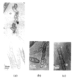
- a carbon nanobell (non-patent document 3, FIG. 1) connected with a bell-like structure having a length of 10 nm ⁇ diameter of about 10 nm, and a sphere with a length of 30 nm ⁇ diameter of about 30 nm synthesized by a thermal plasma method are connected.
- Nano-necklace Non-Patent Document 4, FIG. 2)
- bamboo-type nanotube synthesized by MPECVD method Non-Patent Document 5, FIG.
- JP 2003-12312 A Japanese Patent No. 5119451 Japanese Patent No. 5428066
- An object of the present invention is to provide a novel nanocarbon material using a submarine type substrate heating method (subsurface CVD method) developed by the present inventors.
- a bottom portion composed of a multi-layer graphene layer, a tapered reduced hollow body portion having a smaller number of stacked graphene layers than the bottom portion, and a diameter gradually decreasing, and a tip opening portion, and the maximum of the bottom portion Pot-type nanocarbon whose aspect ratio between diameter and total length is 4 or more.
- the number of stacked graphene layers is smaller than that of the tapered reduced hollow body portion and the diameter is larger, but the diameter is smaller than the diameter of the bottom portion.
- a plurality of the pot-type nanocarbons according to any one of [1] to [3] are connected, A carbon nanopot in which the bottom of the adjacent pot-type nanocarbon and the tip opening are connected.
- a liquid tank filled with an organic liquid serving as a carbon source A liquid communication part that is mounted in the liquid tank so as to be movable up and down, and is provided so that the organic liquid is introduced from the bottom, and the catalyst-carrying substrate at a position that does not directly contact the organic liquid introduced from the liquid communication part
- a heating device for heating the catalyst-carrying substrate installed in the reaction chamber Using a carbon nanomaterial manufacturing apparatus having an inert gas supply apparatus that supplies an inert gas to the space in the reaction chamber, After attaching the catalyst-carrying substrate in the reaction chamber, while supplying an inert gas to the space in the reaction chamber, the reaction chamber is submerged in the organic liquid in the liquid tank, and the organic liquid is discharged from the liquid communication portion.
- a method of introducing a carbon-containing gas from an organic liquid into a space in the reaction chamber to be introduced into the reaction chamber and growing a carbon nanomaterial on the catalyst-carrying substrate The catalyst-carrying substrate includes a catalyst-dispersed nanosheet carried on the substrate, A method for producing a carbon nanopot, comprising heating the catalyst-carrying substrate to 750 to 950 ° C. to grow nanocarbon deposited on the catalyst-carrying substrate to obtain the carbon nanopot according to [4] .
- a liquid tank filled with an organic liquid serving as a carbon source A liquid communication part that is mounted in the liquid tank so as to be movable up and down, and is provided so that the organic liquid is introduced from the bottom, and the catalyst-carrying substrate at a position that does not directly contact the organic liquid introduced from the liquid communication part
- a heating device for heating the catalyst-carrying substrate installed in the reaction chamber Using a carbon nanomaterial manufacturing apparatus having an inert gas supply apparatus that supplies an inert gas to the space in the reaction chamber, After attaching the catalyst-carrying substrate in the reaction chamber, while supplying an inert gas to the space in the reaction chamber, the reaction chamber is submerged in the organic liquid in the liquid tank, and the organic liquid is discharged from the liquid communication portion.
- a method of introducing a carbon-containing gas from an organic liquid into a space in the reaction chamber to be introduced into the reaction chamber and growing a carbon nanomaterial on the catalyst-carrying substrate The catalyst-carrying substrate includes a catalyst-dispersed nanosheet carried on the substrate, The catalyst-carrying substrate is heated to 750 to 950 ° C. to grow nanocarbon deposited on the catalyst-carrying substrate, The catalyst-carrying substrate on which the nanocarbon has been grown is immersed in an organic solvent to separate the connecting portions of adjacent pot-type nanocarbons, and is isolated according to any one of [1] to [3]
- a method for producing pot-type nanocarbon, comprising obtaining pot-type nanocarbon.
- a liquid tank filled with an organic liquid serving as a carbon source A liquid communication part that is mounted in the liquid tank so as to be movable up and down, and is provided so that the organic liquid is introduced from the bottom, and the catalyst-carrying substrate at a position that does not directly contact the organic liquid introduced from the liquid communication part
- a heating device for heating the catalyst-carrying substrate installed in the reaction chamber Using a carbon nanomaterial manufacturing apparatus having an inert gas supply apparatus that supplies an inert gas to the space in the reaction chamber, After attaching the catalyst-carrying substrate in the reaction chamber, while supplying an inert gas to the space in the reaction chamber, the reaction chamber is submerged in the organic liquid in the liquid tank, and the organic liquid is discharged from the liquid communication portion.
- a method of introducing a carbon-containing gas from an organic liquid into a space in the reaction chamber to be introduced into the reaction chamber and growing a carbon nanomaterial on the catalyst-carrying substrate The catalyst-carrying substrate includes a catalyst-dispersed nanosheet carried on the substrate, The catalyst-carrying substrate is heated to 750 to 950 ° C., and nanocarbon deposited on the catalyst-carrying substrate is grown.
- the bottom part is composed of a multilayer graphene layer, and the number of stacked graphene layers is smaller than the bottom part and the diameter is smaller.
- a pot having a tapered diameter-reduced hollow body including two or more regions that gradually become smaller and have different diameter-reduction ratios, and a tip opening, and an aspect ratio of a maximum diameter and a total length of the bottom is 4 or more
- the bottom of the multilayer graphene layer is formed by immersing the catalyst-supporting substrate on which the carbon nanopot is grown in an organic solvent and cutting the portion where the diameter reduction ratio of the tapered diameter hollow body of the pot-type nanocarbon changes. And isolating the pot-type nanocarbon having a tapered reduced hollow body having a smaller number of graphene layers than the bottom and a gradually decreasing diameter.
- a liquid tank filled with an organic liquid serving as a carbon source A liquid communication part that is mounted in the liquid tank so as to be movable up and down, and is provided so that the organic liquid is introduced from the bottom, and the catalyst-carrying substrate at a position that does not directly contact the organic liquid introduced from the liquid communication part
- a heating device for heating the catalyst-carrying substrate installed in the reaction chamber Using a carbon nanomaterial manufacturing apparatus having an inert gas supply apparatus that supplies an inert gas to the space in the reaction chamber, After attaching the catalyst-carrying substrate in the reaction chamber, while supplying an inert gas to the space in the reaction chamber, the reaction chamber is submerged in the organic liquid in the liquid tank, and the organic liquid is discharged from the liquid communication portion.
- a method of introducing a carbon-containing gas from an organic liquid into a space in the reaction chamber to be introduced into the reaction chamber and growing a carbon nanomaterial on the catalyst-carrying substrate The catalyst-carrying substrate includes a catalyst-dispersed nanosheet carried on the substrate, The catalyst-carrying substrate is heated to 750 to 950 ° C. to grow carbon deposited on the catalyst-carrying substrate, and the bottom part composed of a multilayer graphene layer and the number of graphene layers stacked are smaller than the bottom part and the diameter gradually increases.
- the bottom of the multilayer graphene layer is formed by immersing the catalyst-supporting substrate on which the carbon nanopot has grown in an organic solvent and cutting at the switching site between the tapered reduced diameter hollow body and the widened hollow neck of the pot-type nanocarbon.
- the catalyst-carrying substrate includes graphene oxide, graphene, h-boron nitride, ruthenium oxide, titanium oxide, zinc oxide, aluminum oxide, silicon oxide, cerium oxide, niobium oxide, zirconium oxide, thallium oxide, barium titanate, A catalyst-dispersed nanosheet in which a catalyst is dispersed in a nanosheet containing a dispersion medium selected from molybdenum sulfide, tin sulfide, tungsten sulfide, thallium sulfide, niobium sulfide, molybdenum telluride, and a mixed crystal combining these is applied to a substrate.
- a dispersion medium selected from molybdenum sulfide, tin sulfide, tungsten sulfide, thallium sulfide, niobium sulfide, molybdenum telluride, and a mixed crystal
- the catalyst-carrying substrate is formed by applying the catalyst-dispersed nanosheet to the substrate and then irradiating with ultraviolet rays.
- the catalyst is Cr, Fe, Co, Ni, Cu, Mo, Pt, Pd, Rh, Ir, Y, La, Ce, Pr, Nd, Gd, Tb, Dy, Ho, Er, Lu, or these
- the method according to [9] or [10] comprising an element selected from the combination of:
- the pot-type nanocarbon of the present invention has a necked bottom shape, and can be expected to be used as a nanoscale bottomed container such as a nanoflask or a nanoampule.
- Non-Patent Document 3 is a TEM image of carbon nanobell disclosed in Non-Patent Document 3. It is the high-resolution TEM image (a) and TEM image (b) of the nano necklace currently disclosed by the nonpatent literature 4.
- 6 is a TEM image of a bamboo-type carbon nanotube disclosed in Non-Patent Document 5.
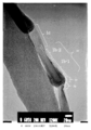
- FIG. 5 is a TEM image of the pot-type nanocarbon (carbon nanopot) in a connected state
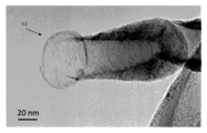
- FIG. 6 is a TEM image of the tip opening
- FIG. 7 is a TEM image of the isolated pot-type nanocarbon.
- the novel carbon nanopot of the present invention includes a bottom portion 1a made of a multilayer graphene layer, and a tapered reduced diameter hollow cylinder having a smaller number of stacked graphene layers and a gradually decreasing diameter than the bottom portion 1a.
- a plurality of pot-type nanocarbons (FIG. 7A) having a portion 1d (FIG. 6) are connected, and the bottom 1a and the tip opening 1d of the adjacent pot-type nanocarbon are connected.
- the tapered diameter-reduced hollow body 1b has regions 1b-1 and 1b-2 with different diameter-reduction rates.
- the diameter reduction rate of the region 1b-1 is larger than the diameter reduction rate of the region 1b-2.
- the graphene layers constituting the bottom 1a are curved and stacked to form the bottom of the pot-type container.
- the bottom portion 1a is preferably formed by stacking 10 to 80 layers of graphene nanosheets onion-like, having a diameter of 15 to 100 nm, preferably about 50 nm, and a length of about 10 to 50 nm, preferably about 20 nm.
- the tapered diameter hollow body 1b is preferably laminated in a taper shape in which 10 to 80 graphene nanosheets are gradually reduced in diameter, and the number of laminations decreases as the distance from the bottom 1a increases.
- the average diameter of the cavity 1b having a tapered diameter is 15 to 100 nm, preferably about 50 nm, and the length is 35 to 300 nm, preferably about 200 nm.
- the tapered diameter-reduced hollow body portion 1b has the regions 1b-1 and 1b-2 having different diameter reduction ratios, the area 1b-1 having a large diameter reduction ratio is preferably 10 to 80 layers where the number of graphene nanosheets is large.
- the number of layers is preferably 8 to 50, and the diameter is preferably 15 to 100 nm at the maximum and preferably 14 to 60 nm at the minimum.
- the number of graphene layers stacked is preferably 8 to 50 on the bottom side, and preferably 6 to 20 on the tip opening side, and the diameter is preferably substantially constant. 12 to 60 nm.
- the inner diameter of the hollow portion of the tapered diameter-reduced hollow body is substantially constant, and is preferably 30 to 45% of the diameter of the bottom portion.
- the widened hollow neck is preferably laminated in a taper shape in which 6 to 20 layers of graphene nanosheets are gradually widened, the average diameter is 12 to 60 nm, preferably about 40 nm, and the length is 10 to 250 nm, preferably It is about 50 nm.
- the taper of the widened hollow neck is smaller than the taper of the hollow portion with a reduced diameter.
- the inner diameter of the hollow portion of the widened hollow neck expands in the same manner as the diameter, and is preferably 30 to 60% of the diameter on the tapered reduced diameter hollow barrel side, and preferably 60 to 90% of the diameter on the tip opening side. is there.
- the overall length of the pot-type nanocarbon is 70 to 350 nm, preferably about 200 nm.
- the total length of the carbon nanopot formed by connecting a plurality of pot-type nanocarbons is preferably 10 to 200 ⁇ m, and many 20 to 100 ⁇ m are formed.
- the interval between the graphene nanosheets in the portion where the graphene layers are laminated is 0.33 to 0.70 nm, preferably about 0.34 nm.
- the inner graphene nanosheet extends from the bottom 1a to the reduced-diameter hollow body 1b, and the outer graphene nanosheet increases in the bottom 1a, and decreases as the reduced-diameter hollow body 1b approaches the widened hollow neck 1c.
- the aspect ratio of the maximum diameter of the bottom 1a and the overall length across the bottom 1a, tapered reduced hollow body 1b, wide hollow neck 1c and tip opening 1d is 4 or more, preferably 4 or more and 20 or less. Preferably they are 4 or more and 10 or less.
- the nanopot of the present invention is different in that the tapered reduced hollow body portion and the widened hollow neck portion are long grown, and can be said to be a carbon nanomaterial having a novel structure.
- the carbon nanopot of the present invention is connected in a state where the tip opening of the preceding pot-type nanocarbon accepts the bottom of the subsequent pot-type nanocarbon, and is a nanobell-type formed by stacking cups or bells. And the structure of the connecting part is different. Furthermore, the cup stack type (Patent Document 2) has a bottomless shape with both ends open, and the carbon nanopot of the present invention is also different in that it has a bottomed shape.
- the carbon nanopot of the present invention includes a connecting portion in which the leading end portion of the preceding pot-type nanocarbon accepts the bottom portion of the succeeding pot-type nanocarbon, and a contraction of the tapered reduced hollow body portion. Separation is possible at a portion where the diameter ratio changes (a boundary between the regions 1b-1 and 1b-2) or a switching portion between the tapered reduced diameter hollow body and the widened hollow neck.
- a bottom portion composed of a multilayer graphene layer, a tapered reduced hollow body having a smaller number of graphene layers than the bottom and a gradually decreasing diameter, and a tip opening, and the maximum diameter and total length of the bottom
- the pot-type nanocarbon ((a) in FIG. 7) having an aspect ratio of 4 or more can be isolated.
- Pot-type nanocarbon is isolated by immersing the catalyst-supported substrate on which the carbon nanopot has grown in an organic solvent such as methanol, ethanol, 2-propanol, 1-butanol, acetone, hexane, and the like by stirring or ultrasonication. This can be done by applying vibration.
- organic solvent such as methanol, ethanol, 2-propanol, 1-butanol, acetone, hexane, and the like by stirring or ultrasonication. This can be done by applying vibration.
- the carbon nanopot of the present invention can be manufactured by a submarine type substrate heating method (subsurface CVD method) using a carbon nanomaterial manufacturing apparatus (Japanese Patent No. 5428066) developed by the present inventors.
- a carbon nanomaterial manufacturing apparatus Japanese Patent No. 5428066
- the carbon nanomaterial manufacturing apparatus 30 is provided such that a liquid tank 31 that is filled with an organic liquid 6 that serves as a carbon source and a liquid tank 31 that can be moved up and down, and the organic liquid 6 is introduced from the bottom 200A.
- a liquid communication part 8 a substrate support means for detachably attaching the catalyst support substrate 4 to a position not in direct contact with the organic liquid 6 introduced from the liquid communication part 8, and a gas around the catalyst support substrate 4 is filled
- a reaction chamber 200 having a space 2 a to be heated, a heating device 5 for heating the catalyst-carrying substrate 4 installed in the reaction chamber 200, and an inert gas IG supplied to the space 2 a in the reaction chamber 200.
- a cooling device 10 such as a cooling jacket is provided on the outer wall of the liquid tank 31 to prevent the organic liquid 6 from being overheated.
- a reflux device 18 for condensing and refluxing the evaporated gas of the organic liquid 6 flowing through the opening 36 drilled in the center of the lid member 33 is provided so as to protrude upward from the lid member 33.
- the reflux device 18 includes a closed tube 19 that is open at only one end that communicates with the opening 36, and a cooling tube device 22 that enters the closed tube 19 into the condensation tube portion 20 and circulates and communicates with the outside. .
- a refrigerant fluid such as water is flowed into the cooling pipe of the cooling pipe device 22 to condense and liquefy the evaporating gas in the condensation pipe part 20 and return it to the organic liquid storage part of the liquid tank 31.
- symbol 37 in a figure is a release hole of inert gas or organic liquid evaporative gas.
- the reaction chamber 200 is attached to the liquid tank 31 so as to be movable up and down by an electrode 35 of the heating device 5 provided so as to penetrate the lid member 33 of the liquid tank 31.
- the reaction chamber 200 has an opening 200A on the lower surface, and is formed in a hollow three-dimensional rectangular shape with the lower surface opened by the four peripheral walls and the top wall.
- the reaction chamber 200 is made of a heat-resistant material that does not chemically react with an organic liquid, such as quartz glass or other structural wall.
- the heating device 5 includes a heater 5a, an electrode 35, and an external DC power supply 34.
- the heater 5 a is attached to the peripheral wall of the reaction chamber 200, but it can also be inserted from the bottom 200 ⁇ / b> A of the reaction chamber 200 and attached to the bottom surface of the catalyst carrying substrate 4.
- a management device 44 electrically connected to the inert gas supply device 7, the external power supply 34, and a radiation thermometer (not shown) as a substrate temperature detection sensor is provided.
- the management device 44 controls the processes such as insertion and pulling of the reaction chamber 200 into the organic liquid 6, heating by the heating device 5, generation of the synthesis temperature condition, and completion of the synthesis while detecting the temperature with the substrate temperature detection sensor.
- a controller or the like having an arithmetic control function is used.
- the reaction chamber 200 After attaching the catalyst-carrying substrate 4 in the reaction chamber 200, the reaction chamber 200 is submerged in the organic liquid 6 in the liquid tank 31 while supplying the inert gas IG to the space 2 a in the reaction chamber 200. Then, the organic liquid 6 is introduced into the reaction chamber 200 from the liquid communication portion 9, and a gas containing carbon is evaporated from the organic liquid 6 into the space 2 a in the reaction chamber 200. Synthesize nanomaterials.
- the catalyst-carrying substrate 4 includes catalyst-dispersed nanosheets carried on the substrate, and the catalyst-carrying substrate 4 is heated to 750 to 950 ° C., preferably 830 to 850 ° C., by the heating device 5. The carbon deposited on it is grown.
- the atmosphere around the catalyst-carrying substrate 4 is brought into an oxygen-free or low-oxygen state to prevent oxidation of the catalyst.
- the catalyst-carrying substrate 4 is heated to 750 to 950 ° C., preferably 830 to 850 ° C. by the heating device 5 while supplying the inert gas IG, the gas containing carbon from the organic liquid 6 is easily evaporated by radiant heat, Mix with the inert gas IG in the space 2a.
- the temperature is lower than 830 ° C., more carbon nanofibers having a uniform thickness are generated.
- the generation of carbon nanopots cannot be confirmed.
- the supply of the inert gas IG is not interrupted and continues to be supplied while the catalyst-carrying substrate 4 is installed in the reaction chamber 200.
- the content of the gas containing carbon in the mixed gas during the synthesis reaction is preferably 50% or less, and more preferably 1 to 25%.
- the heating device 5 directly heats the catalyst supporting substrate 4, the organic liquid 6 is heated by the radiant heat from the heating device 5 or the substrate 4 heated by the heating device 5. For this reason, the initial temperature of vaporization of the gas containing carbon that evaporates from the organic liquid 6 is lower than the boiling point, and the temperature gradient with the catalyst-carrying substrate 4 heated to 750 to 950 ° C. is large.
- the gas containing low-temperature carbon deposited on the surface of the high-temperature catalyst-carrying substrate 4 is decomposed by the catalyst particles, and carbon atoms are stacked on the surface of the catalyst particles and grow.
- the reaction chamber 200 is pulled up from the liquid tank 31 to collect the nanocarbon material. Since the inert gas IG is continuously supplied even during cooling, the generation of impurities and amorphous carbon is prevented even when the temperature of the catalyst-carrying substrate 4 is lowered.
- hydrocarbons As the organic liquid serving as the carbon source to be filled in the liquid tank 31, hydrocarbons, alcohols, esters, ketones, organic acids and other carbon compounds that are liquid at normal temperature and pressure can be suitably used.
- the hydrocarbon is preferably a linear or cyclic hydrocarbon having 5 to 18 carbon atoms, and examples thereof include pentane, hexane, heptane, benzene, toluene and the like.
- the alcohol a linear or cyclic monohydric alcohol or polyhydric alcohol having 1 to 16 carbon atoms is preferable, and examples thereof include methanol, ethanol, 1-propanol, 2-propanol, 1-butanol, and ethylene glycol. .
- the ester is preferably a chain or cyclic ester having 2 or more carbon atoms, and examples thereof include ethyl formate, methyl acetate, and methyl butyrate.
- the ketone is preferably a chain or cyclic ketone having 3 or more carbon atoms, and examples thereof include acetone, methyl ethyl ketone, and cyclohexane.
- the organic acid is preferably a saturated or unsaturated carboxylic acid or oxycarboxylic acid having 1 to 10 carbon atoms, and examples thereof include formic acid, acetic acid, propionic acid, and oleic acid. Examples of other carbon compounds include diethyl ether and diisopropyl ether. Of these, a volatile organic liquid at normal temperature is preferable, and a lower alcohol is particularly preferable.
- a rare gas such as argon (Ar), helium (He), neon (Ne), or the like can be preferably used.
- the catalyst-carrying substrate attached to the reaction chamber 200 for growing the carbon nanopot is composed of a substrate and a catalyst-dispersed nanosheet on the substrate.
- silica, alumina, zeolite, MgO, zirconia, titania or the like can be used as the substrate.
- An inorganic material such as a silicon substrate, a heat-resistant glass substrate, or a quartz substrate, an organic material such as a polymer substrate, or a composite material thereof can also be used.
- a Si substrate with a thermally oxidized SiO 2 film is preferable.
- Catalyst dispersed nanosheets are graphene oxide, graphene, h-boron nitride, ruthenium oxide, titanium oxide, zinc oxide, aluminum oxide, silicon oxide, cerium oxide, niobium oxide, zirconium oxide, thallium oxide, barium titanate, molybdenum sulfide, sulfide One to several layers of atoms or one to several unit cells in which the catalyst is dispersed in a nanosheet containing a dispersion medium selected from tin, tungsten sulfide, thallium sulfide, niobium sulfide, molybdenum telluride, and a mixed crystal combining these.
- a nanosheet with a thickness of one piece in addition to the above dispersion medium, different elements such as boron or nitrogen for graphene oxide and graphene, carbon for h-boron nitride, sodium, magnesium, potassium, calcium, cesium for other dispersion medium Bismuth, manganese, cobalt and iron may be added.
- different elements such as boron or nitrogen for graphene oxide and graphene, carbon for h-boron nitride, sodium, magnesium, potassium, calcium, cesium for other dispersion medium Bismuth, manganese, cobalt and iron may be added.
- the catalyst-carrying substrate is formed by applying a catalyst-dispersed nanosheet to the substrate and preferably irradiating with ultraviolet rays.
- the formation of the catalyst-carrying substrate will be described by taking as an example the case where the nanosheet on which the catalyst is dispersed is a graphene oxide nanosheet.
- a catalyst is dispersed in a dispersion in which graphene oxide nanosheets are dispersed to prepare a catalyst-supported graphene oxide dispersion.
- the catalyst is preferably dispersed as a metal salt containing a carboxylic acid group such as a catalyst metal acetate.
- the catalyst-supported graphene oxide dispersion is dropped onto the substrate, and the catalyst-supported graphene oxide nanosheet is attached to the substrate surface.
- the oxygen-containing functional group and the carbon atom to which the oxygen-containing functional group is bonded are removed from the graphene oxide, and a minute hole is formed on the surface of the graphene oxide nanosheet.
- carboxylic acid groups such as acetic acid groups are also removed from the catalyst metal salt, and catalyst metal fine particles are formed on the surface of the graphene oxide nanosheet.
- the graphene oxide nanosheet with the catalyst metal fine particles supported on the surface overlaps the substrate, thereby forming a catalyst-supported substrate having nanometer-order protrusions on the surface (FIG. 11).
- the nanosheet in which the catalyst metal fine particles are dispersed has high affinity with the catalyst metal, and the catalyst metal fine particles are not peeled off from the nanosheet during the growth reaction of the carbon nanopot.
- Catalysts include Cr, Fe, Co, Ni, Cu, Mo, Pt, Pd, Rh, Ir, Y, La, Ce, Pr, Nd, Gd, Tb, Dy, Ho, Er, Lu, or combinations thereof. It is preferable that the selected element is included.
- the catalyst metal salt a carboxylate containing these elements is preferable, and an acetate is more preferable. In particular, iron acetate, cobalt acetate, nickel acetate, molybdenum acetate and the like are preferable.
- FIGS 9A and 9B schematically show the growth mechanism of the carbon nanopot of the present invention.
- a high temperature gradient in the reaction chamber causes a temperature gradient in the catalyst metal protruding on the surface of the catalyst-dispersed nanosheet. That is, the catalyst metal on the surface of the catalyst-dispersed nanosheet is in a liquid state, the gas containing carbon in contact with the catalyst metal is decomposed by the action of the catalyst metal, and the carbon atoms are dissolved and diffused in the catalyst metal (1), It is deposited as graphene nanosheets on the projecting portions of the catalytic metal, which is at a relatively low temperature (2).
- the graphene nanosheet is formed along the curved surface of the catalyst metal as carbon atoms are precipitated from the inside of the catalyst metal or diffused on the surface, and further, a new graphene nanosheet layer is sequentially formed therebelow. In this way, the formation of the bottom part and the trunk part of the pot-type nanocarbon proceeds.
- the catalyst metal containing a large amount of carbon and having a high affinity (wetting property) with the graphene nanosheet protrudes into a protrusion shape while being in contact with the entire inner wall of the body (3) to (4).
- the catalyst metal containing a large amount of carbon is sucked into the body by capillary action.
- the catalyst metal on the surface of the graphene oxide nanosheet which is a catalyst-dispersed nanosheet on the substrate, also contains a lot of carbon, it has a high affinity with the graphene oxide nanosheet, and some of the catalyst metal adheres to the graphene oxide nanosheet and the substrate It remains on (5).
- the elongated catalyst metal forms an additional graphene nanosheet layer inside the barrel.
- the surface area per unit length of the cylinder decreases in inverse proportion to the cylinder diameter, so when the same amount of carbon atoms precipitates to form the graphene nanosheet cylinder, As the diameter becomes smaller, the cylinder length tends to become longer, a region with a smaller diameter reduction ratio appears, and a tapered diameter-reduced body is formed (6) to (7).
- the catalyst metal further expands, the carbon atom melts from the exposed catalyst metal surface, and the path of diffusion to the catalyst metal tip in the trunk becomes longer, and the tip in the extension direction that becomes the bottom of the pot-type nanocarbon As the distance from the substrate increases, the temperature of that portion rapidly decreases and the diffusion coefficient of carbon in the catalyst metal decreases, so the carbon atom concentration at the tip of the catalyst metal decreases. Along with this, the wettability of the catalytic metal in the trunk portion with respect to the graphene nanosheet becomes worse, and the capillary action becomes weaker.
- the catalytic metal on the graphene oxide nanosheet on the substrate maintains high wettability with respect to the graphene oxide nanosheet
- the catalytic metal in the body is pulled back from the body to the graphene oxide nanosheet side by the surface tension.
- a widened hollow neck is formed while the diameter of the projection of the catalyst metal is increased (8)
- the laminated graphene nanosheet becomes a hollow tubular shape, and the tip opening is in a state in which a plurality of graphene nanosheets are laminated ( 9).
- the catalyst metal pulled back returns to the stage (2), and the next graphene nanosheet lamination is repeated (10).
- the nanocarbon material thus formed includes a bottom portion 1a composed of a multilayer graphene layer in which a plurality of graphene nanosheets shown in FIGS. 5 and 6 are laminated, and a tapered shape in which the number of graphene layers laminated is smaller than that of the bottom portion 1a and the diameter gradually decreases.
- a plurality of pot-type nanocarbons having an opening 1d are connected, and a carbon nanopot in which the bottom 1a of the adjacent pot-type nanocarbon and the tip opening 1d are connected.
- a region 1b-2 having a small diameter reduction ratio 1b-1 is generated. Furthermore, the region 1b-2 having a small diameter reduction ratio of the body portion may be extended, and the widened hollow neck portion 1c may not be formed.
- the catalyst-carrying substrate on which carbon is grown is immersed in an organic solvent, and the diameter reduction rate of the bottom part and the tip opening part where the adjacent pot-type nanocarbons are connected and the tapered diameter hollow body part 1b is abrupt. It is also possible to obtain an isolated pot-type nanocarbon by separating at a portion that changes to, or at the boundary between the tapered reduced diameter hollow body portion 1b and the widened hollow neck portion 1c.
- the organic solvent lower alcohols such as methanol, ethanol, 1-propanol, 2-propanol and 1-butanol, ketones such as acetone, hexane and the like can be used. While immersed in an organic solvent, mechanical external force such as stirring or ultrasonic vibration may be applied.
- Si substrate with thermally oxidized SiO 2 film (SUMCO, Si purity 99.999%, single-sided mirror surface, 0.5 mm thickness, n-type, (100) surface, resistivity 1 to 10 ⁇ cm, thermally oxidized film thickness 300 nm as a substrate ) was used.
- the substrate was cut into a size of 9 mm ⁇ 14 mm with a diamond pen, and then ultrasonically washed with acetone and 2-propanol for 30 minutes each to prepare a SiO 2 / Si substrate.
- catalyst-carrying substrate 1) Hydrophilization of the surface of the SiO 2 / Si substrate using a plasma processing unit CUTE-1MP / R manufactured by FEMTO SCIENCE, with a degree of vacuum of 7.33 ⁇ 10 ⁇ 1 Torr, a frequency of 50 kHz, a power of 140 W, and an irradiation time of 1 minute. did. 2) Using a micropipette, a drop of 1.5 ⁇ L of catalyst-supported graphene oxide dispersion water was dropped at the center of the substrate. 3) The substrate was allowed to stand at room temperature, and the dropped catalyst solution was dried.
- the ultra-high pressure mercury lamp was irradiated with ultraviolet rays for 3 hours on the catalyst on the SiO 2 / Si substrate in an oxygen atmosphere.
- the functional groups (carboxyl group, epoxy group, etc.) bonded to graphene oxide are removed by ultraviolet irradiation in an oxygen atmosphere, the carbon atoms to which these functional groups are bonded are removed together. It was confirmed with an atomic force microscope (AFM) that catalytic metal fine particles were formed on the surface of graphene oxide and the surface was uneven (FIGS. 10 and 11).
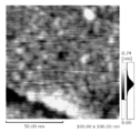
- FIG. 10 is an AFM image measured using an SPM-8000FM manufactured by Shimadzu Corporation after applying a graphene oxide sheet in which no catalyst metal is dispersed on a SiO 2 / Si substrate and irradiating it with ultraviolet rays. It can be seen that irregularities of 5 nm are formed. The height of the unevenness is about 0.3 nm, which corresponds to the thickness of one graphene sheet. This minute unevenness is considered to be a scaffold for forming metal catalyst fine particles.
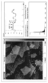
- FIG. 11 is an AFM image measured using a Nanoscope V manufactured by Digital Instrument after applying graphene oxide sheet in which a catalyst metal is dispersed to a SiO 2 / Si substrate and irradiating with ultraviolet rays. It can be seen that several sheet-like substances (graphene oxide sheets) are placed on the surface of the SiO 2 / Si substrate surface (A) while being overlapped, and catalyst metal fine particles having a size of 10 to 20 nm are formed on the sheet surface. . Since formation of catalyst fine particles having a size of about 40 nm larger than that is recognized on the SiO 2 / Si substrate surface (A), it can be seen that the graphene oxide sheet is effective for making catalyst metal fine particles.
- graphene oxide sheet is effective for making catalyst metal fine particles.
- the upper right diagram in FIG. 11 shows the cross-sectional profile of the AFM image along the straight line shown in the left diagram.
- the protrusions indicated by arrows (a) to (e) in the upper right cross-sectional profile view correspond to the fine particles indicated by arrows in the left AFM image.
- the average height of the fine particles (a) to (c) formed on the graphene oxide sheet is about 1 nm, and the height of the fine particles (d) and (e) formed on the SiO 2 / Si substrate is 3 nm, respectively. And about 5 nm.
- composition 1) By a submarine type substrate heating method (subsurface CVD method) using a carbon nanomaterial manufacturing apparatus (FIG. 8, except that the heating carbon sheet is brought into close contact with the back surface of the catalyst carrying substrate instead of the heater 5). Nanocarbon materials were synthesized in a reaction chamber submerged in a liquid used as a carbon raw material. 2) 2-propanol was used as a carbon raw material. 3) While injecting argon gas at a flow rate of 0.2 L / min into a reaction chamber having a volume of about 10 cm 3 with an open bottom, the reaction chamber was filled with argon gas. 4) A current was passed through the carbon sheet adhered to the back surface of the catalyst carrying substrate, and the catalyst carrying substrate was heated to 840 ° C.
- the surrounding 2-propanol evaporates from the opening at the bottom of the reaction chamber and flows into the reaction chamber, and a mixed gas of argon gas and 2-propanol around the catalyst support substrate (content of 2-propanol is 1 to 50%) Came to exist. Since the temperature of the liquid surface of 2-propanol is about 50 ° C. and the temperature of the catalyst supporting substrate is 750 to 950 ° C., the temperature of the reaction space around the catalyst supporting graphene oxide (catalyst dispersed nanosheet) on the catalyst supporting substrate The gradient was extremely large at about 700 to 900 ° C. per 1 cm. 5) After heating for 10 minutes, the current was turned off, and the catalyst-carrying substrate was naturally cooled to room temperature (about 5 minutes), and then the reaction chamber was lifted out of the solution to recover the catalyst-carrying substrate.
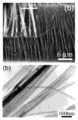
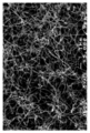
- FIG. 12 is an SEM image of 5,000 times, and it can be seen that a large number of carbon nanopots whose thickness changes periodically are entangled and grown on the substrate.
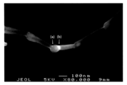
- FIG. 13 is an SEM image at a magnification of 80,000 times, showing an example in which the joint surface (a) between the pot-type nanocarbons, the boundary (b) between the tapered reduced diameter hollow body and the widened hollow neck is clearly observed. .
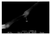
- FIG. 14 is an SEM image of 120,000 times, and it can be seen that the tip opening of the pot-type nanocarbon covers the bottom of the adjacent pot-type nanocarbon.
- a nanocarbon product was sampled from a catalyst-carrying substrate under a stereomicroscope using a sampling instrument (Microsupport, Quick Joy and Flex Probe (tip diameter: 5 ⁇ m)), and a TEM micro sample was obtained. It was produced by moving onto a grid (Oken Shoji, Type A, STEM150Cu grid, carbon reinforced, grid pitch 150 ⁇ m). Observation was performed with TEM (JEOL, JEM-2000FX) and FE-TEM (FEI, TECNAI F20), and the acceleration voltage was 200 kV for both. Observation images are shown in FIGS.
- connection portion between the bottom of the adjacent nanopot and the tip opening is weakly bonded.
- FIG. 17 shows a stacked state of graphene nanosheets in the tapered reduced hollow body portion of the carbon nanopot.
- the interval between the graphene nanosheets was 0.34 nm.
- the arrows in the figure indicate graphene edges exposed on the outer surface.
- FIG. 18 is a TEM image of the widened hollow neck, and it can be seen that the layer structure of the graphene sheet is maintained up to the bottom of the subsequent nanopot while reducing the number of layers (in this example, at least 5 layers).
- FIG. 19 is an SEM image obtained by observing the surface of the graphene oxide sheet on the catalyst-carrying substrate after the synthesis experiment.
- Catalyst metal particles (b) shown as white particles are observed.
- the catalyst metal fine particles (b) have produced the pot-type nanocarbon (c ′)
- the bottom of the next pot-type nanocarbon and the tapered reduced diameter hollow body the gray portion around the catalyst metal fine particles (b)
- the generation process is interrupted during the formation.
- FIG. 7 (a) is a TEM image of pot-type nanocarbon isolated by cutting the connecting portion between the bottom of the adjacent carbon nanopot and the tip opening. Note that (b) in FIG. 7 seems to be an isolated nanobell because no reduced diameter portion is seen.
- FIG. 1 For comparison, a Raman spectrum of a bamboo-type carbon nanotube is shown in FIG.
- bamboo type nanotubes are the above-mentioned [4.
- carbon nanofibers having a uniform thickness that are often produced when synthesis is performed with the catalyst-supporting substrate temperature set at 820 ° C.
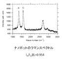
- FIG. 20 shows that the intensity ratio I D / I G between the D band and the G band of the carbon nanopot is 0.954
- FIG. 21 shows that I D / I G of the bamboo nanotube is 1.33.
- Comparison between the integrated intensity ratios of the D band and G band suggests that the hexagonal lattice structure of the carbon nanopot has better crystallinity or larger crystallite size than that of the bamboo-type nanotube. This is thought to be due to the feature that the graphene layer inside the nanopot has a cylindrical tube structure similar to that of the multi-walled carbon nanotube from the bottom to the front of the widened neck.
- the D band of the carbon nanopot is observed more strongly than the carbon nanotube because the graphene edges are particularly densely exposed on the outer surface of the tapered reduced diameter hollow body in the carbon nanopot than the other portions. This is in good agreement with the TEM observation result (FIG. 17).
- the carbon nanopot of the present invention can be expected to be used as a functional filler for composite materials (high sensitivity strain response, sound insulation, shock absorption, etc.) and an electrode material for lithium ion batteries.
- the pot-type nanocarbon obtained by isolating the carbon nanopot of the present invention can be used as a nanoscale bottomed container such as a nanoflask or a nanoampule, and can be expected to be applied to drug delivery.
Landscapes
- Chemical & Material Sciences (AREA)
- Organic Chemistry (AREA)
- Engineering & Computer Science (AREA)
- Materials Engineering (AREA)
- Chemical Kinetics & Catalysis (AREA)
- Inorganic Chemistry (AREA)
- Carbon And Carbon Compounds (AREA)
- Catalysts (AREA)
- Battery Electrode And Active Subsutance (AREA)
- Fuel Cell (AREA)
Abstract
新規なナノカーボン材料を提供する。多層グラフェン層からなる底部1aと、底部1aよりもグラフェン層の積層数が少なく且つ直径が徐々に小さくなるテーパード縮径中空胴部1bと、テーパード縮径中空胴部1bよりもグラフェン層の積層数が少なく且つ直径が大きいが底部1aの直径よりは小さい直径の拡幅中空首部1cと、拡幅中空首部1cの先端開口部1dと、を有するポット型ナノカーボンが複数連結してなり、隣接するポット型ナノカーボンの底部1aと先端開口部1dとが連結しているカーボンナノポット。
Description
本発明は、新規なナノカーボン材料及びその製造方法に関し、特に、グラフェンナノシートの成長が異なる領域を有するポット型ナノカーボン材料及びその製造方法に関する。
カーボンナノチューブは、特異の電子物性、吸着特性、機械的特性を有することから、例えば、走査型プローブ顕微鏡(SPM)探針、電界放出ディスプレイ(FED)用エミッタ、燃料電池用水素吸蔵材料、リチウム二次電池負極材料、高密度集積回路、高性能樹脂複合材料など、極めて広範囲の応用が期待され、特に、近時は高品質のカーボンナノチューブを安定して量産できる方法が模索されている。カーボンナノチューブ(Carbon Nano Tube:CNT)は、グラファイトの層を丸めた円筒状構造で生成される炭素微結晶であり、その製造方法として従来、アーク放電法、レーザ蒸発法、化学気相成長法(CVD)などが知られている。アーク放電法及びレーザ蒸発法は、高品質又は高純度のカーボンナノチューブを得ることができる反面、収量が少なく、工業的に量産することが困難であった。CVD法は、炭素源となる炭素化合物を原料ガスとして供給出来るために大量合成に向くが、カーボンナノチューブの結晶性に劣る。
基板上に金属触媒を堆積し、該基板を有機液体中で加熱してCNTを合成する方法(特許文献1、非特許文献1及び2)も提案されているが、有機液体中に基板を浸漬して金属触媒を有機液体に直接に接触させた状態でCNTを合成させる(液中基板加熱法)ので基板がCNTの最適合成温度に到達する前に基板上の触媒が有機液体と反応してしまうため、安定して純度の高いカーボンナノチューブを得ることができなかった。また、触媒に関しては、有機液体に溶出する触媒材料はカーボンナノチューブ合成時に基板から剥離してしまうため、用いることができない。したがって、有機液体に溶出しにくい例えば鉄、コバルト、鉄系合金等を触媒として選択しなければならなかった。さらに、基板への触媒膜の付着力を高めるために、基板上にスパッタ法や真空蒸着法などでFe薄膜を堆積し、さらにFe薄膜を堆積した基板を水素プラズマ処理することによりFeを島状に微粒子とするとともに、基板に強固に結合させる必要があり、高価なスパッタ装置やプラズマ処理装置を必要とし、設備コスト、製造コストが高価となる問題があった。そこで、本発明者は、内部を閉じた槽体に有機液体を収容し、残部の容積空間を反応空間とし、触媒担持基板の加熱により合成条件を生成させて有機液体の蒸発ガスを炭素源ガスとして触媒上にナノカーボン材料を気相成長させるサブマリン式基板加熱法を提案した(特許文献3)。
一方、ナノカーボン材料としては、代表的なカーボンナノチューブ(CNT、SWCNT)の他に、カップスタック型カーボンナノチューブ及びこれを単離したカップ型ナノカーボン(特許文献2)、H2プラズマ処理により合成される長さ10nm×直径10nm程度のベル様構造が連結しているカーボンナノベル(非特許文献3、図1)、熱プラズマ法により合成される長さ30nm×直径30nm程度の球が連結しているナノネックレス(非特許文献4、図2)、MPECVD法により合成されたバンブー型ナノチューブ(非特許文献5、図3)、Sn触媒を用いるCVD法において炭素源としてのC2H2流量を変えて合成される異なる形状のカーボンナノ材料として、直線状カーボンナノファイバーからなるフラワー型(図4(a~b))、長さ1.5μm×直径0.85μm程度の数珠状ナノカーボンファイバー(図4(c~d))、ナノカーボンコイル(図4(e~h))及びツイスト型ナノカーボンチューブ(図4(i~j))などが報告され(非特許文献6)、種々の分野での応用が検討されている。
K.Nakagawa et al.,Catalysis Letters,101,191(2005)
M.Nishitani−Gamo et al.,Japanese Journal of Applied Physics,46,6329(2007)
Ma et al.Size−controlled short nanobells:Growth and formation mechanism,Applied Physics Letters,Vol.77,No.25,18 December 2000
H.Okuno et al.,Synthsis of carbon nanotubes and nano−necklacs by thermal plasma process,Carbon 42(2004)2543−2549
E.G.Wang et al.Optical emission spectroscopy study of the influence of nitrogen on carbon nanotube growth,Carbon 41,1827(2003)
J.Sun et al.,Synthesis of carbon nanocoil forests on BaSrTiO3 substrates with the aid of a Sn catalyst,Carbon 60(2013)5−15
Y.Matsumoto et al.Photoreaction of Graphene Oxide Nanosheets in Water,J.Phys.Chem.C 2011,115,19280−19286
本発明者らが開発したサブマリン式基板加熱法(液面下CVD法)を用いて、新規なナノカーボン材料を提供することを目的とする。
本発明者らは、先に提案したサブマリン式基板加熱法を継続研究し、特定の条件下で新規なナノカーボン材料を製造することができることを知見して、本発明を完成するに至った。本発明の具体的態様は以下のとおりである。
[1]多層グラフェン層からなる底部と、当該底部よりもグラフェン層の積層数が少なく且つ直径が徐々に小さくなるテーパード縮径中空胴部と、先端開口部と、を有し、当該底部の最大直径と全長とのアスペクト比が4以上であるポット型ナノカーボン。
[2]前記テーパード縮径中空胴部は、縮径率が異なる2以上の領域を含む、[1]に記載のポット型ナノカーボン。
[3]前記テーパード縮径中空胴部と前記先端開口部との間に、前記テーパード縮径中空胴部よりもグラフェン層の積層数が少なく且つ直径が大きいが前記底部の直径よりは小さい直径の拡幅中空首部をさらに有する、[1]又は[2]に記載のポット型ナノカーボン。
[4][1]~[3]のいずれかに記載のポット型ナノカーボンが複数連結してなり、
隣接するポット型ナノカーボンの底部と先端開口部とが連結しているカーボンナノポット。
[5]炭素源となる有機液体を充填する液体槽と、
当該液体槽内に昇降可能に取り付けられており、底部から有機液体が導入されるように設けられている液体連通部、当該液体連通部から導入された有機液体と直接接触しない位置に触媒担持基板を脱着可能に取り付ける基板支持手段、及び当該基板支持手段の周囲に気体を充填させる空間を具備する反応室と、
当該反応室内に設置された触媒担持基板を加熱する加熱装置と、
当該反応室内の空間に不活性ガスを供給する不活性ガス供給装置と、を有するカーボンナノ材料製造装置を用いて、
当該反応室内に触媒担持基板を取り付けた後、当該反応室内の空間に不活性ガスを供給しながら、当該反応室を当該液体槽内の有機液体中に沈めて、当該液体連通部から有機液体を当該反応室内に導入し、有機液体からカーボンを含むガスを当該反応室内の空間に蒸散させて、当該触媒担持基板上でカーボンナノ材料を成長させる方法であって、
当該触媒担持基板は、基板上に担持されている触媒分散ナノシートを含み、
当該触媒担持基板を750~950℃に加熱して、触媒担持基板上に堆積したナノカーボンを成長させ、[4]に記載のカーボンナノポットを得ることを特徴とする、カーボンナノポットの製造方法。
[6]炭素源となる有機液体を充填する液体槽と、
当該液体槽内に昇降可能に取り付けられており、底部から有機液体が導入されるように設けられている液体連通部、当該液体連通部から導入された有機液体と直接接触しない位置に触媒担持基板を脱着可能に取り付ける基板支持手段、及び当該基板支持手段の周囲に気体を充填させる空間を具備する反応室と、
当該反応室内に設置された触媒担持基板を加熱する加熱装置と、
当該反応室内の空間に不活性ガスを供給する不活性ガス供給装置と、を有するカーボンナノ材料製造装置を用いて、
当該反応室内に触媒担持基板を取り付けた後、当該反応室内の空間に不活性ガスを供給しながら、当該反応室を当該液体槽内の有機液体中に沈めて、当該液体連通部から有機液体を当該反応室内に導入し、有機液体からカーボンを含むガスを当該反応室内の空間に蒸散させて、当該触媒担持基板上でカーボンナノ材料を成長させる方法であって、
当該触媒担持基板は、基板上に担持されている触媒分散ナノシートを含み、
当該触媒担持基板を750~950℃に加熱して、触媒担持基板上に堆積したナノカーボンを成長させ、
当該ナノカーボンを成長させた前記触媒担持基板を有機溶媒中に浸漬させて、隣接するポット型ナノカーボンの連結部を分離させて、[1]~[3]のいずれかに記載の単離したポット型ナノカーボンを得ることを特徴とする、ポット型ナノカーボンの製造方法。
[7]炭素源となる有機液体を充填する液体槽と、
当該液体槽内に昇降可能に取り付けられており、底部から有機液体が導入されるように設けられている液体連通部、当該液体連通部から導入された有機液体と直接接触しない位置に触媒担持基板を脱着可能に取り付ける基板支持手段、及び当該基板支持手段の周囲に気体を充填させる空間を具備する反応室と、
当該反応室内に設置された触媒担持基板を加熱する加熱装置と、
当該反応室内の空間に不活性ガスを供給する不活性ガス供給装置と、を有するカーボンナノ材料製造装置を用いて、
当該反応室内に触媒担持基板を取り付けた後、当該反応室内の空間に不活性ガスを供給しながら、当該反応室を当該液体槽内の有機液体中に沈めて、当該液体連通部から有機液体を当該反応室内に導入し、有機液体からカーボンを含むガスを当該反応室内の空間に蒸散させて、当該触媒担持基板上でカーボンナノ材料を成長させる方法であって、
当該触媒担持基板は、基板上に担持されている触媒分散ナノシートを含み、
当該触媒担持基板を750~950℃に加熱して、触媒担持基板上に堆積したナノカーボンを成長させて、多層グラフェン層からなる底部と、当該底部よりもグラフェン層の積層数が少なく且つ直径が徐々に小さくなり且つ縮径率が異なる2以上の領域を含むテーパード縮径中空胴部と、先端開口部と、を有し、当該底部の最大直径と全長とのアスペクト比が4以上であるポット型ナノカーボンが連結しているカーボンナノポットを成長させ、
当該カーボンナノポットが成長した前記触媒担持基板を有機溶媒中に浸漬させて、ポット型ナノカーボンのテーパード縮径中空胴部の縮径率が変化する部位で切断して、多層グラフェン層からなる底部及び当該底部よりもグラフェン層の積層数が少なく且つ直径が徐々に小さくなるテーパード縮径中空胴部を有するポット型ナノカーボンを単離することを含む、ポット型ナノカーボンの製造方法。
[8]炭素源となる有機液体を充填する液体槽と、
当該液体槽内に昇降可能に取り付けられており、底部から有機液体が導入されるように設けられている液体連通部、当該液体連通部から導入された有機液体と直接接触しない位置に触媒担持基板を脱着可能に取り付ける基板支持手段、及び当該基板支持手段の周囲に気体を充填させる空間を具備する反応室と、
当該反応室内に設置された触媒担持基板を加熱する加熱装置と、
当該反応室内の空間に不活性ガスを供給する不活性ガス供給装置と、を有するカーボンナノ材料製造装置を用いて、
当該反応室内に触媒担持基板を取り付けた後、当該反応室内の空間に不活性ガスを供給しながら、当該反応室を当該液体槽内の有機液体中に沈めて、当該液体連通部から有機液体を当該反応室内に導入し、有機液体からカーボンを含むガスを当該反応室内の空間に蒸散させて、当該触媒担持基板上でカーボンナノ材料を成長させる方法であって、
当該触媒担持基板は、基板上に担持されている触媒分散ナノシートを含み、
当該触媒担持基板を750~950℃に加熱して、触媒担持基板上に堆積したカーボンを成長させて、多層グラフェン層からなる底部と、当該底部よりもグラフェン層の積層数が少なく且つ直径が徐々に小さくなるテーパード縮径中空胴部と、当該テーパード縮径中空胴部よりもグラフェン層の積層数が少なく且つ直径が大きいが当該底部の直径よりは小さい直径の拡幅中空首部と、先端開口部と、を有し、当該底部の最大直径と全長とのアスペクト比が4以上であるポット型ナノカーボンが連結しているカーボンナノポットを成長させ、
当該カーボンナノポットが成長した前記触媒担持基板を有機溶媒中に浸漬させて、ポット型ナノカーボンのテーパード縮径中空胴部と拡幅中空首部との切り替え部位で切断して、多層グラフェン層からなる底部及び当該底部よりもグラフェン層の積層数が少なく且つ直径が徐々に小さくなるテーパード縮径中空胴部を有するポット型ナノカーボンを単離することを含む、ポット型ナノカーボンの製造方法。
[9]前記触媒担持基板は、酸化グラフェン、グラフェン、h−窒化ホウ素、酸化ルテニウム、酸化チタン、酸化亜鉛、酸化アルミニウム、酸化ケイ素、酸化セリウム、酸化ニオブ、酸化ジルコニウム、酸化タリウム、チタン酸バリウム、硫化モリブデン、硫化スズ、硫化タングステン、硫化タリウム、硫化ニオブ、テルル化モリブデン、及びこれらを組み合わせた混晶から選択される分散媒を含むナノシートに触媒が分散されてなる触媒分散ナノシートを基板に塗布して形成することを特徴とする、[5]~[8]のいずれかに記載の方法。
[10]前記触媒担持基板は、前記触媒分散ナノシートを基板に塗布した後に紫外線照射することにより形成されることを特徴とする、[9]に記載の方法。
[11]前記触媒は、Cr、Fe、Co、Ni、Cu、Mo、Pt、Pd、Rh、Ir、Y、La、Ce、Pr、Nd、Gd、Tb、Dy、Ho、Er、Lu又はこれらの組み合わせから選択される元素を含むことを特徴とする[9]又は[10]に記載の方法。
[1]多層グラフェン層からなる底部と、当該底部よりもグラフェン層の積層数が少なく且つ直径が徐々に小さくなるテーパード縮径中空胴部と、先端開口部と、を有し、当該底部の最大直径と全長とのアスペクト比が4以上であるポット型ナノカーボン。
[2]前記テーパード縮径中空胴部は、縮径率が異なる2以上の領域を含む、[1]に記載のポット型ナノカーボン。
[3]前記テーパード縮径中空胴部と前記先端開口部との間に、前記テーパード縮径中空胴部よりもグラフェン層の積層数が少なく且つ直径が大きいが前記底部の直径よりは小さい直径の拡幅中空首部をさらに有する、[1]又は[2]に記載のポット型ナノカーボン。
[4][1]~[3]のいずれかに記載のポット型ナノカーボンが複数連結してなり、
隣接するポット型ナノカーボンの底部と先端開口部とが連結しているカーボンナノポット。
[5]炭素源となる有機液体を充填する液体槽と、
当該液体槽内に昇降可能に取り付けられており、底部から有機液体が導入されるように設けられている液体連通部、当該液体連通部から導入された有機液体と直接接触しない位置に触媒担持基板を脱着可能に取り付ける基板支持手段、及び当該基板支持手段の周囲に気体を充填させる空間を具備する反応室と、
当該反応室内に設置された触媒担持基板を加熱する加熱装置と、
当該反応室内の空間に不活性ガスを供給する不活性ガス供給装置と、を有するカーボンナノ材料製造装置を用いて、
当該反応室内に触媒担持基板を取り付けた後、当該反応室内の空間に不活性ガスを供給しながら、当該反応室を当該液体槽内の有機液体中に沈めて、当該液体連通部から有機液体を当該反応室内に導入し、有機液体からカーボンを含むガスを当該反応室内の空間に蒸散させて、当該触媒担持基板上でカーボンナノ材料を成長させる方法であって、
当該触媒担持基板は、基板上に担持されている触媒分散ナノシートを含み、
当該触媒担持基板を750~950℃に加熱して、触媒担持基板上に堆積したナノカーボンを成長させ、[4]に記載のカーボンナノポットを得ることを特徴とする、カーボンナノポットの製造方法。
[6]炭素源となる有機液体を充填する液体槽と、
当該液体槽内に昇降可能に取り付けられており、底部から有機液体が導入されるように設けられている液体連通部、当該液体連通部から導入された有機液体と直接接触しない位置に触媒担持基板を脱着可能に取り付ける基板支持手段、及び当該基板支持手段の周囲に気体を充填させる空間を具備する反応室と、
当該反応室内に設置された触媒担持基板を加熱する加熱装置と、
当該反応室内の空間に不活性ガスを供給する不活性ガス供給装置と、を有するカーボンナノ材料製造装置を用いて、
当該反応室内に触媒担持基板を取り付けた後、当該反応室内の空間に不活性ガスを供給しながら、当該反応室を当該液体槽内の有機液体中に沈めて、当該液体連通部から有機液体を当該反応室内に導入し、有機液体からカーボンを含むガスを当該反応室内の空間に蒸散させて、当該触媒担持基板上でカーボンナノ材料を成長させる方法であって、
当該触媒担持基板は、基板上に担持されている触媒分散ナノシートを含み、
当該触媒担持基板を750~950℃に加熱して、触媒担持基板上に堆積したナノカーボンを成長させ、
当該ナノカーボンを成長させた前記触媒担持基板を有機溶媒中に浸漬させて、隣接するポット型ナノカーボンの連結部を分離させて、[1]~[3]のいずれかに記載の単離したポット型ナノカーボンを得ることを特徴とする、ポット型ナノカーボンの製造方法。
[7]炭素源となる有機液体を充填する液体槽と、
当該液体槽内に昇降可能に取り付けられており、底部から有機液体が導入されるように設けられている液体連通部、当該液体連通部から導入された有機液体と直接接触しない位置に触媒担持基板を脱着可能に取り付ける基板支持手段、及び当該基板支持手段の周囲に気体を充填させる空間を具備する反応室と、
当該反応室内に設置された触媒担持基板を加熱する加熱装置と、
当該反応室内の空間に不活性ガスを供給する不活性ガス供給装置と、を有するカーボンナノ材料製造装置を用いて、
当該反応室内に触媒担持基板を取り付けた後、当該反応室内の空間に不活性ガスを供給しながら、当該反応室を当該液体槽内の有機液体中に沈めて、当該液体連通部から有機液体を当該反応室内に導入し、有機液体からカーボンを含むガスを当該反応室内の空間に蒸散させて、当該触媒担持基板上でカーボンナノ材料を成長させる方法であって、
当該触媒担持基板は、基板上に担持されている触媒分散ナノシートを含み、
当該触媒担持基板を750~950℃に加熱して、触媒担持基板上に堆積したナノカーボンを成長させて、多層グラフェン層からなる底部と、当該底部よりもグラフェン層の積層数が少なく且つ直径が徐々に小さくなり且つ縮径率が異なる2以上の領域を含むテーパード縮径中空胴部と、先端開口部と、を有し、当該底部の最大直径と全長とのアスペクト比が4以上であるポット型ナノカーボンが連結しているカーボンナノポットを成長させ、
当該カーボンナノポットが成長した前記触媒担持基板を有機溶媒中に浸漬させて、ポット型ナノカーボンのテーパード縮径中空胴部の縮径率が変化する部位で切断して、多層グラフェン層からなる底部及び当該底部よりもグラフェン層の積層数が少なく且つ直径が徐々に小さくなるテーパード縮径中空胴部を有するポット型ナノカーボンを単離することを含む、ポット型ナノカーボンの製造方法。
[8]炭素源となる有機液体を充填する液体槽と、
当該液体槽内に昇降可能に取り付けられており、底部から有機液体が導入されるように設けられている液体連通部、当該液体連通部から導入された有機液体と直接接触しない位置に触媒担持基板を脱着可能に取り付ける基板支持手段、及び当該基板支持手段の周囲に気体を充填させる空間を具備する反応室と、
当該反応室内に設置された触媒担持基板を加熱する加熱装置と、
当該反応室内の空間に不活性ガスを供給する不活性ガス供給装置と、を有するカーボンナノ材料製造装置を用いて、
当該反応室内に触媒担持基板を取り付けた後、当該反応室内の空間に不活性ガスを供給しながら、当該反応室を当該液体槽内の有機液体中に沈めて、当該液体連通部から有機液体を当該反応室内に導入し、有機液体からカーボンを含むガスを当該反応室内の空間に蒸散させて、当該触媒担持基板上でカーボンナノ材料を成長させる方法であって、
当該触媒担持基板は、基板上に担持されている触媒分散ナノシートを含み、
当該触媒担持基板を750~950℃に加熱して、触媒担持基板上に堆積したカーボンを成長させて、多層グラフェン層からなる底部と、当該底部よりもグラフェン層の積層数が少なく且つ直径が徐々に小さくなるテーパード縮径中空胴部と、当該テーパード縮径中空胴部よりもグラフェン層の積層数が少なく且つ直径が大きいが当該底部の直径よりは小さい直径の拡幅中空首部と、先端開口部と、を有し、当該底部の最大直径と全長とのアスペクト比が4以上であるポット型ナノカーボンが連結しているカーボンナノポットを成長させ、
当該カーボンナノポットが成長した前記触媒担持基板を有機溶媒中に浸漬させて、ポット型ナノカーボンのテーパード縮径中空胴部と拡幅中空首部との切り替え部位で切断して、多層グラフェン層からなる底部及び当該底部よりもグラフェン層の積層数が少なく且つ直径が徐々に小さくなるテーパード縮径中空胴部を有するポット型ナノカーボンを単離することを含む、ポット型ナノカーボンの製造方法。
[9]前記触媒担持基板は、酸化グラフェン、グラフェン、h−窒化ホウ素、酸化ルテニウム、酸化チタン、酸化亜鉛、酸化アルミニウム、酸化ケイ素、酸化セリウム、酸化ニオブ、酸化ジルコニウム、酸化タリウム、チタン酸バリウム、硫化モリブデン、硫化スズ、硫化タングステン、硫化タリウム、硫化ニオブ、テルル化モリブデン、及びこれらを組み合わせた混晶から選択される分散媒を含むナノシートに触媒が分散されてなる触媒分散ナノシートを基板に塗布して形成することを特徴とする、[5]~[8]のいずれかに記載の方法。
[10]前記触媒担持基板は、前記触媒分散ナノシートを基板に塗布した後に紫外線照射することにより形成されることを特徴とする、[9]に記載の方法。
[11]前記触媒は、Cr、Fe、Co、Ni、Cu、Mo、Pt、Pd、Rh、Ir、Y、La、Ce、Pr、Nd、Gd、Tb、Dy、Ho、Er、Lu又はこれらの組み合わせから選択される元素を含むことを特徴とする[9]又は[10]に記載の方法。
本発明によれば、新規な形状のナノカーボン材料が提供される。本発明のポット型ナノカーボンは、首長有底形状を有し、ナノフラスコ、ナノアンプルなどナノスケールの有底容器としての利用が期待できる。
以下、添付図面を参照しながら、本発明を詳細に説明する。
図5は連結した状態のポット型ナノカーボン(カーボンナノポット)のTEM画像であり、図6は先端開口部のTEM画像であり、図7は単離したポット型ナノカーボンのTEM画像である。
本発明の新規なカーボンナノポットは、図5に示すように、多層グラフェン層からなる底部1aと、当該底部1aよりもグラフェン層の積層数が少なく且つ直径が徐々に小さくなるテーパード縮径中空胴部1bと、当該テーパード縮径中空胴部1bよりもグラフェン層の積層数が少なく且つ直径が大きいが当該底部1aの直径よりは小さい直径の拡幅中空首部1cと、当該拡幅中空首部1cの先端開口部1d(図6)と、を有するポット型ナノカーボン(図7中(a))が複数連結してなり、隣接するポット型ナノカーボンの底部1aと先端開口部1dとが連結している。テーパード縮径中空胴部1bは、縮径率の異なる領域1b−1及び1b−2を有する。領域1b−1の縮径率は、領域1b−2の縮径率よりも大きい。図示してはいないが、テーパード縮径中空胴部の縮径率が緩やかな領域1b−2が伸長して、拡幅中空首部1cが形成されない場合もある。底部1aを構成するグラフェン層は湾曲して積層し、ポット型容器の底部を形成する。
底部1aは、好ましくは10層~80層のグラフェンナノシートがオニオンライクに積層しており、直径は15~100nm、好ましくは50nm程度であり、長さは10~50nm、好ましくは20nm程度である。
テーパード縮径中空胴部1bは、好ましくは10層~80層のグラフェンナノシートが徐々に縮径するテーパー状に積層し、底部1aから離間するにつれて積層数が減少する。テーパード縮径中空洞部1bの平均直径は15~100nm、好ましくは50nm程度であり、長さは35~300nm、好ましくは200nm程度である。テーパード縮径中空胴部1bが縮径率の異なる領域1b−1及び1b−2を有する場合、縮径率の大きな領域1b−1は、グラフェンナノシートの積層数が多いところで好ましくは10~80層であり、少ないところで好ましくは8~50層であり、直径は最大で好ましくは15~100nm、最小で好ましくは14~60nmである。縮径率の小さな領域1b−2は、グラフェン層の積層数が底部側で好ましくは8~50層であり、先端開口部側で好ましくは6~20層であり、直径はほぼ一定で好ましくは12~60nmである。テーパード縮径中空胴部の中空部の内径は、ほぼ一定で、好ましくは底部の直径の30~45%である。
拡幅中空首部は、好ましくは6~20層のグラフェンナノシートが徐々に拡幅するテーパー状に積層しており、平均直径は12~60nm、好ましくは40nm程度であり、長さは10~250nm、好ましくは50nm程度である。拡幅中空首部のテーパーは、縮径中空洞部のテーパーよりも小さい。拡幅中空首部の中空部の内径は、直径と同様に拡大し、テーパード縮径中空胴部側で好ましくは直径の30~60%であり、先端開口部側で好ましくは直径の60~90%である。
ポット型ナノカーボン単体の全長は70~350nm、好ましくは200nm程度である。複数のポット型ナノカーボンが連結してなるカーボンナノポットの全長は、好ましくは10~200μmであり、20~100μmが多く形成される。
グラフェン層が積層している部分におけるグラフェンナノシートの間隔は0.33~0.70nm、好ましくは0.34nm程度である。内側のグラフェンナノシートは底部1aから縮径中空胴部1bにわたって伸長しており、外側のグラフェンナノシートは底部1aに多く、縮径中空胴部1bから拡幅中空首部1cに近づくにつれて減少する。
底部1aの最大直径と、底部1a、テーパード縮径中空胴部1b、拡幅中空首部1c及び先端開口部1dにわたる全体の長さと、のアスペクト比は4以上であり、好ましくは4以上20以下、より好ましくは4以上10以下である。これまで報告されているナノベル型(図1)、ネックレス型(図2)、バンブー型(図3)、及び数珠型(図4(c)及び(d))のアスペクト比は1~2であり、本発明のナノポットはテーパード縮径中空胴部及び拡幅中空首部が長く成長している点で異なり、新規構造のカーボンナノ材料といえる。
また、本発明のカーボンナノポットは、先行するポット型ナノカーボンの先端開口部が後続するポット型ナノカーボンの底部を受け容れた状態で連結しており、カップ若しくはベルが積層してなるナノベル型とは連結部分の構造が異なっている。さらに、カップスタック型(特許文献2)は両端部が開口となっている無底形状であり、本発明のカーボンナノポットは有底形状である点でも異なっている。
さらに、本発明のカーボンナノポットは、先行するポット型ナノカーボンの先端開口部が後続するポット型ナノカーボンの底部を受け容れた状態で連結している連結部、テーパード縮径中空胴部の縮径率の変化する部位(領域1b−1と1b−2との境界)もしくはテーパード縮径中空胴部と拡幅中空首部との切り替え部位で分離可能である。多層グラフェン層からなる底部と、当該底部よりもグラフェン層の積層数が少なく且つ直径が徐々に小さくなるテーパード縮径中空胴部と、先端開口部と、を有し、当該底部の最大直径と全長とのアスペクト比が4以上であるポット型ナノカーボン(図7中(a))を単離することができる。ポット型ナノカーボンの単離は、カーボンナノポットが成長した触媒担持基板をメタノール、エタノール、2−プロパノール、1−ブタノール、アセトン、ヘキサンなどの有機溶媒に浸漬させて、撹拌又は超音波処理などにより振動を付与することにより行うことができる。
本発明のカーボンナノポットは、本発明者が開発したカーボンナノ材料製造装置(日本特許5428066号)を用いるサブマリン式基板加熱法(液面下CVD法)により製造することができる。本発明で用いるカーボンナノ材料製造装置の一例を図8に示す。
カーボンナノ材料製造装置30は、炭素源となる有機液体6を充填する液体槽31と、当該液体槽31内に昇降可能に取り付けられており、底部200Aから有機液体6が導入されるように設けられている液体連通部8、当該液体連通部8から導入された有機液体6と直接接触しない位置に触媒担持基板4を脱着可能に取り付ける基板支持手段、及び触媒担持基板4の周囲に気体を充填させる空間2aを具備する反応室200と、当該反応室200内に設置された触媒担持基板4を加熱する加熱装置5と、当該反応室200内の空間2aに不活性ガスIGを供給する不活性ガス供給装置7と、を有する。
液体槽31の外壁には冷却ジャケットなどの冷却装置10が設けられており、有機液体6が過熱されることを防止する。蓋部材33の中央に穿孔した開口36を介して通流する有機液体6の蒸発ガスを凝縮還流させる還流装置18が蓋部材33から上方に突設して設けられている。還流装置18は、開口36に連通する一端のみを開口した閉鎖筒管19と、閉鎖筒管19内に凝縮管部20を突入させて外部に循環連通する冷却管装置22と、を備えている。冷却管装置22の冷却管内に水等の冷媒流体を流して凝縮管部20で蒸発ガスを凝縮液化させ液体槽31の有機液体貯留部へ還流させる。なお、図中符号37は、不活性ガス又は有機液体蒸発ガスのリリース孔である。
反応室200は、液体槽31の蓋部材33に貫通して設けられている加熱装置5の電極35によって、液体槽31に昇降可能に取り付けられる。反応室200は、下面の開口200Aを有し、四周壁と天壁とにより下面を開口した中空立体矩形状で構成されている。反応室200は耐熱性で有機液体と化学反応しない素材、たとえば石英ガラスその他の構造物壁体から構成される。
加熱装置5は、ヒータ5a、電極35、外部の直流電源34を含む。図8では、ヒータ5aが反応室200の周壁に取り付けられているが、反応室200の底部200Aから挿入して触媒担持基板4の底面に取り付けることもできる。
不活性ガス供給装置7、外部電源34、基板温度検出センサとしての放射温度計(図示せず)に電気的に接続された管理装置44が設けられている。管理装置44は、反応室200の有機液体6内への挿入、引き上げ、加熱装置5による加熱、合成温度条件生成、合成終了、などの工程を基板温度検出センサで温度検出しながら制御する管理手段であり、たとえば演算制御機能を備えたコントローラ等が用いられる。
次に、カーボンナノ材料製造装置30を用いて、カーボンナノポットを製造する方法を説明する。
反応室200内に触媒担持基板4を取り付けた後、当該反応室200内の空間2aに不活性ガスIGを供給しながら、当該反応室200を当該液体槽31内の有機液体6中に沈めて、当該液体連通部9から有機液体6を当該反応室200内に導入し、有機液体6からカーボンを含むガスを当該反応室200内の空間2aに蒸散させて、当該触媒担持基板4上でカーボンナノ材料を合成する。当該触媒担持基板4は、基板上に担持されている触媒分散ナノシートを含み、当該触媒担持基板4を加熱装置5により750~950℃、好ましくは830~850℃に加熱して、触媒担持基板4上に堆積したカーボンを成長させる。
反応室200内の空間2aに不活性ガスIGを供給して酸素と置換することによって、触媒担持基板4周囲の雰囲気を無酸素もしくは低酸素状態として、触媒の酸化を防止する。不活性ガスIGを供給しながら、触媒担持基板4を加熱装置5により750~950℃、好ましくは830~850℃に加熱すると、有機液体6からのカーボンを含む気体が輻射熱によって蒸散しやすくなり、空間2a内で不活性ガスIGと混合する。830℃より低温では、太さが均一なカーボンナノファイバーの方が多く生成されるようになり、750℃未満ではカーボンナノポットの生成を確認できなかった。850℃を越えると枝分かれ型のカーボンナノファイバーの方が多く生成されるようになり、950℃を越えるとカーボンナノポットの生成を確認できなかった。日本特許5428066号に開示されている方法と異なり、不活性ガスIGの供給は中断せず、反応室200に触媒担持基板4を設置している間中、供給し続ける。合成反応中の混合ガス中のカーボンを含む気体の含有量は50%以下とすることが好ましく、1~25%がより好ましい。
加熱装置5は触媒担持基板4を直接加熱するため、有機液体6は加熱装置5ないし加熱装置5に加熱された基板4からの輻射熱で加熱される。このため、有機液体6から蒸散するカーボンを含む気体の蒸散当初の温度は沸点より低く、750~950℃に加熱される触媒担持基板4との温度勾配が大きい。高温の触媒担持基板4表面に堆積した低温のカーボンを含む気体は触媒粒子によって分解され、炭素原子が触媒粒子の表面に積層して成長する。
加熱装置5による加熱を停止し、触媒担持基板4を自然冷却により室温程度まで冷却した後、反応室200を液体槽31から引き上げて、ナノカーボン材料を回収する。冷却中も不活性ガスIGを供給し続けているため、触媒担持基板4の温度が低下しても、不純物やアモルファスカーボンの生成を防止する。
液体槽31に充填する炭素源となる有機液体としては、常温常圧で液体の炭化水素、アルコール、エステル、ケトン、有機酸その他の炭素化合物を好適に用いることができる。炭化水素としては、炭素数が5~18の鎖状又は環状の炭化水素が好ましく、たとえば、ペンタン、ヘキサン、ヘプタン、ベンゼン、トルエン等が挙げられる。アルコールとしては、炭素数が1~16の鎖状又は環状の一価アルコール又は多価アルコールが好ましく、たとえば、メタノール、エタノール、1−プロパノール、2−プロパノール、1−ブタノール、エチレングリコール等が挙げられる。エステルとしては、炭素数が2以上の鎖状又は環状エステルが好ましく、たとえば、ギ酸エチル、酢酸メチル、酪酸メチル等が挙げられる。ケトンとしては、炭素数が3以上の鎖状又は環状のケトンが好ましく、たとえば、アセトン、メチルエチルケトン、シクロヘキサン等が挙げられる。有機酸としては、炭素数が1~10の飽和又は不飽和のカルボン酸又はオキシカルボン酸が好ましく、たとえば、ギ酸、酢酸、プロピオン酸、オレイン酸等が挙げられる。その他の炭素化合物としては、たとえばジエチルエーテル、ジイソプロピルエーテル等が挙げられる。中でも常温で揮発性の有機液体が好ましく、特に低級アルコールが好ましい。
反応室200に供給し続ける不活性ガスIGとしては、アルゴン(Ar)、ヘリウム(He)、ネオン(Ne)等の希ガスなどを好ましく用いることができる。
反応室200に取り付け、カーボンナノポットを成長させる触媒担持基板は、基板と、基板上の触媒分散ナノシートとからなる。
基板としては、シリカ、アルミナ、ゼオライト、MgO、ジルコニア、チタニア等を用いることができる。シリコン基板、耐熱ガラス基板、石英基板などの無機材料、ポリマー基板等の有機材料、又はこれらの複合材料を用いることもできる。特に、熱酸化SiO2膜付Si基板が好ましい。
触媒分散ナノシートは、酸化グラフェン、グラフェン、h−窒化ホウ素、酸化ルテニウム、酸化チタン、酸化亜鉛、酸化アルミニウム、酸化ケイ素、酸化セリウム、酸化ニオブ、酸化ジルコニウム、酸化タリウム、チタン酸バリウム、硫化モリブデン、硫化スズ、硫化タングステン、硫化タリウム、硫化ニオブ、テルル化モリブデン、これらを組み合わせた混晶から選択される分散媒を含むナノシートに触媒を分散させた、原子1層~数層あるいは単位格子1個~数個分の厚みのナノシートである。触媒分散ナノシートには、上記分散媒に加えて異種元素、たとえば酸化グラフェンとグラフェンについては、ホウ素あるいは窒素、h−窒化ホウ素については炭素、その他の分散媒についてはナトリウム、マグネシウム、カリウム、カルシウム、セシウム、ビスマス、マンガン、コバルト、鉄を添加してもよい。
触媒担持基板は、触媒分散ナノシートを基板に塗布し、好ましくは紫外線照射することにより形成される。
触媒を分散させるナノシートが酸化グラフェンナノシートである場合を例にして触媒担持基板の形成を説明する。
まず、酸化グラフェンナノシートが分散している分散液に触媒を分散させて触媒担持酸化グラフェン分散液を調製する。このとき、触媒は触媒金属酢酸塩等のカルボン酸基を含有する金属塩として分散させることが好ましい。次に、当該触媒担持酸化グラフェン分散液を基板上に滴下して、基板表面に触媒担持酸化グラフェンナノシートを付着させる。次いで、酸素雰囲気中で紫外線を照射することにより、酸化グラフェンから酸素含有官能基及び当該酸素含有官能基が結合している炭素原子が除去され、酸化グラフェンナノシート表面に微小な穴が形成される。同時に触媒金属塩から酢酸基等のカルボン酸基も除去され、触媒金属微粒子が酸化グラフェンナノシート表面に形成される。触媒金属微粒子を表面に担持した状態の酸化グラフェンナノシートが基板上に重なり合うことで、表面にナノメートルオーダーの突起を有する触媒担持基板が形成される(図11)。触媒金属微粒子を分散させるナノシートは、触媒金属との親和性が高く、カーボンナノポットの成長反応中に触媒金属微粒子がナノシートから剥がれることがない。
触媒としては、Cr、Fe、Co、Ni、Cu、Mo、Pt、Pd、Rh、Ir、Y、La、Ce、Pr、Nd、Gd、Tb、Dy、Ho、Er、Lu又はこれらの組み合わせから選択される元素を含むことが好ましい。触媒金属塩としては、これらの元素を含むカルボン酸塩が好ましく、酢酸塩がより好ましい。特に、鉄酢酸塩、コバルト酢酸塩、ニッケル酢酸塩、モリブデン酢酸塩などが好ましい。
本発明のカーボンナノポットの成長機構の概略を図9A及び9Bに示す。
触媒担持基板4が加熱装置5(カーボン板ヒータ)により加熱されると、本方法の特徴である反応室内の高い温度勾配により、触媒分散ナノシート表面において突出している触媒金属にも温度勾配が生じる。すなわち、触媒分散ナノシート表面にある触媒金属は液体状態にあり、触媒金属と接触しているカーボンを含む気体が触媒金属の作用で分解して炭素原子が触媒金属に溶け込んで拡散し(1)、相対的に低温となっている触媒金属の突起部にグラフェンナノシートとして析出する(2)。グラフェンナノシートは、炭素原子が触媒金属内部から析出あるいは表面で拡散することにより触媒金属の曲面に沿って形成され、さらにその下側に新たなグラフェンナノシート層が順次形成される。こうしてポット型ナノカーボンの底部と胴部の形成が進行する。それとともに炭素を多く含んでグラフェンナノシートとの親和性(濡れ性)が高くなっている触媒金属が、胴部内壁全面と接したまま突起状に細長く突き出てくる(3)~(4)。触媒金属表面におけるグラフェンナノシートの形成が進むにつれて、炭素を多く含んだ触媒金属は毛細管作用により胴部内に吸い上げられる。
一方、基板上の触媒分散ナノシートである酸化グラフェンナノシート表面の触媒金属も炭素を多く含んでいるため、酸化グラフェンナノシートとの親和性が高く、一部の触媒金属が酸化グラフェンナノシートに固着して基板上に残る(5)。伸長した触媒金属は、胴部の内側に追加のグラフェンナノシート層を形成していく。グラフェンナノシートの筒径が小さくなるにつれて、筒の単位長さあたりの表面積が筒径に反比例して小さくなるので、同じ量の炭素原子が析出してグラフェンナノシートの筒を形成する際に、筒径が小さくなるほど筒長が長くなる傾向が生じて、縮径率の小さい領域が出現し、テーパード縮径胴部が形成される(6)~(7)。
触媒金属がさらに伸長して、露出している触媒金属面から炭素原子が溶け込んで胴部内の触媒金属先端部まで拡散する道のりが長くなるとともに、ポット型ナノカーボンの底部となる伸長方向先端部が基板から離間するにつれ、その部分の温度が急激に低下して触媒金属内炭素の拡散係数が小さくなるために、触媒金属先端部の炭素原子濃度が減少する。それにつれて、グラフェンナノシートに対する胴部内の触媒金属の濡れ性が悪くなり、毛細管作用が弱くなる。一方、基板上の酸化グラフェンナノシート上の触媒金属は、酸化グラフェンナノシートに対して高い濡れ性を維持しているため、胴部内の触媒金属は、その表面張力により胴部内から酸化グラフェンナノシート側に引き戻されて、その過程で触媒金属の突起の径が大きくなりながら拡幅中空首部を形成し(8)、積層したグラフェンナノシートは中空管状となり、先端開口部は複数のグラフェンナノシートが積層した状態となる(9)。
引き戻された触媒金属は、(2)の段階に戻って次のグラフェンナノシートの積層が繰り返される(10)。こうして形成されたナノカーボン材料は、図5及び6に示す複数のグラフェンナノシートが積層した多層グラフェン層からなる底部1aと、底部1aよりもグラフェン層の積層数が少なく且つ直径が徐々に小さくなるテーパード縮径中空胴部1bと、テーパード縮径中空胴部1bよりもグラフェン層の積層数が少なく且つ直径が大きいが底部1aの直径よりは小さい直径の拡幅中空首部1cと、拡幅中空首部1cの先端開口部1dと、を有するポット型ナノカーボンが複数連結してなり、隣接するポット型ナノカーボンの底部1aと先端開口部1dとが連結しているカーボンナノポットとなる。
また、胴部が成長する間に、新たなグラフェンシートの積層時にグラフェンシートが伸長する割合が大きくなり、グラフェンシートの積層状態が急激に変化する部位が生じ、結果として、縮径率の大きな領域1b−1と縮径率の小さな領域1b−2が生じる。さらに、胴部の縮径率の小さな領域1b−2が伸長して、拡幅中空首部1cが形成されない場合もある。
さらに、カーボンを成長させた前記触媒担持基板を有機溶媒中に浸漬させて、隣接するポット型ナノカーボンが連結している底部と先端開口部、テーパード縮径中空胴部1bの縮径率が急激に変化する部位、又はテーパード縮径中空胴部1bと拡幅中空首部1cとの境界にて分離させて、単離したポット型ナノカーボンを得ることもできる。有機溶媒としては、メタノール、エタノール、1−プロパノール、2−プロパノール、1−ブタノールなどの低級アルコール類、アセトンなどのケトン類、ヘキサンなどを用いることができる。有機溶媒中に浸漬させている間に、撹拌や超音波振動などの機械的外力を付与してもよい。
以下、実施例により本発明をさらに具体的に説明する。
[1.触媒担持酸化グラフェン分散水の調製]
1)グラファイト粉末(和光純薬(株),特級,純度:98.0%,残2%の不純物は酸素)を改良Hummers法(非特許文献7)で酸化処理して酸化グラフェン分散水を得た。
2)酸化グラフェン分散水を純水で5倍に希釈して、希釈酸化グラフェン分散水とした。
3)希釈酸化グラフェン分散水6gに酢酸鉄(II)(ALDRICH、純度99.995%,(CH3COO)2Fe)0.0104gと酢酸コバルト(II)・四水和物(ALDRICH、純度99.998%,(CH3COO)2Co・4H2O)0.0149gを加えてよく混ぜ合わせた後に超音波洗浄器((株)井内盛栄堂製、型式:US−2、超音波出力:80W、発振周波数:38kHz、発振方式:自励発振、槽容量:2.6リットル)を用いて20分間超音波分散を行い、酸化グラフェン・触媒混合液とした。
4)酸化グラフェン・触媒混合液を重力加速度15,000gで20分間遠心分離した。
5)遠心分離した沈殿物に、全重量を6gとなるまで純水を加えてよく撹拌した。
6)さらに、超音波洗浄器で10分間撹拌して触媒担持酸化グラフェン分散水とした。
1)グラファイト粉末(和光純薬(株),特級,純度:98.0%,残2%の不純物は酸素)を改良Hummers法(非特許文献7)で酸化処理して酸化グラフェン分散水を得た。
2)酸化グラフェン分散水を純水で5倍に希釈して、希釈酸化グラフェン分散水とした。
3)希釈酸化グラフェン分散水6gに酢酸鉄(II)(ALDRICH、純度99.995%,(CH3COO)2Fe)0.0104gと酢酸コバルト(II)・四水和物(ALDRICH、純度99.998%,(CH3COO)2Co・4H2O)0.0149gを加えてよく混ぜ合わせた後に超音波洗浄器((株)井内盛栄堂製、型式:US−2、超音波出力:80W、発振周波数:38kHz、発振方式:自励発振、槽容量:2.6リットル)を用いて20分間超音波分散を行い、酸化グラフェン・触媒混合液とした。
4)酸化グラフェン・触媒混合液を重力加速度15,000gで20分間遠心分離した。
5)遠心分離した沈殿物に、全重量を6gとなるまで純水を加えてよく撹拌した。
6)さらに、超音波洗浄器で10分間撹拌して触媒担持酸化グラフェン分散水とした。
[2.基板]
1)基板として、熱酸化SiO2膜付Si基板(SUMCO、Si純度99.999%、片面鏡面、0.5mm厚、n型、(100)面、抵抗率1~10Ωcm、熱酸化膜厚300nm)を用いた。
2)基板をダイヤモンドペンで9mm×14mmの寸法に切りだした後、アセトンと2−プロパノールでそれぞれ30分ずつ超音波洗浄して、SiO2/Si基板を準備した。
1)基板として、熱酸化SiO2膜付Si基板(SUMCO、Si純度99.999%、片面鏡面、0.5mm厚、n型、(100)面、抵抗率1~10Ωcm、熱酸化膜厚300nm)を用いた。
2)基板をダイヤモンドペンで9mm×14mmの寸法に切りだした後、アセトンと2−プロパノールでそれぞれ30分ずつ超音波洗浄して、SiO2/Si基板を準備した。
[3.触媒担持基板の調製]
1)FEMTO SCIENCE社製プラズマ処理器CUTE−1MP/Rを用いて、真空度7.33×10−1Torr,周波数50kHz,パワー140W,照射時間1分間でSiO2/Si基板の表面を親水化した。
2)マイクロピペットを用いて、触媒担持酸化グラフェン分散水1.5μLを基板の中心に一滴滴下した。
3)基板を室温で静置して、滴下した触媒液を乾燥させた。
4)超高圧水銀灯により、酸素雰囲気中でSiO2/Si基板上の触媒に3時間紫外線を照射した。酸素雰囲気中での紫外線照射により、酸化グラフェンに結合している官能基(カルボキシル基、エポキシ基など)の一部が外れる際に、これらの官能基が結合している炭素原子が一緒に外れ、酸化グラフェン表面に触媒金属微粒子が形成され、表面が凸凹になっていることを原子間力顕微鏡(AFM)で確認した(図10、図11)。
1)FEMTO SCIENCE社製プラズマ処理器CUTE−1MP/Rを用いて、真空度7.33×10−1Torr,周波数50kHz,パワー140W,照射時間1分間でSiO2/Si基板の表面を親水化した。
2)マイクロピペットを用いて、触媒担持酸化グラフェン分散水1.5μLを基板の中心に一滴滴下した。
3)基板を室温で静置して、滴下した触媒液を乾燥させた。
4)超高圧水銀灯により、酸素雰囲気中でSiO2/Si基板上の触媒に3時間紫外線を照射した。酸素雰囲気中での紫外線照射により、酸化グラフェンに結合している官能基(カルボキシル基、エポキシ基など)の一部が外れる際に、これらの官能基が結合している炭素原子が一緒に外れ、酸化グラフェン表面に触媒金属微粒子が形成され、表面が凸凹になっていることを原子間力顕微鏡(AFM)で確認した(図10、図11)。
図10は触媒金属を分散していない酸化グラフェンシートをSiO2/Si基板に塗布して紫外線照射したのちに、島津製作所製SPM−8000FMを用いて測定したAFM像である。5nm大の凹凸が形成されていることがわかる。凹凸の高低さは0.3nm程度であり、グラフェンシート1層分の厚みに相当している。この微小な凹凸が金属触媒微粒子形成の足場となっていると考えられる。
図11は触媒金属を分散した酸化グラフェンシートをSiO2/Si基板に塗布して紫外線照射した後に、Digital Instrument製Nanoscope Vを用いて測定したAFM像である。SiO2/Si基板面(A)の表面にシート状物質(酸化グラフェンシート)がいくつかは重なり合いながら載っており、そのシート表面に10~20nm大の触媒金属微粒子が形成されているのがわかる。SiO2/Si基板面(A)にはそれよりも大きな40nm程度の大きさの触媒微粒子の形成が認められるので、酸化グラフェンシートが触媒金属の微粒子化に効果的であることがわかる。
図11の右上図はAFM像の断面プロフィールを左図に示した直線に沿って表したものである。右上の断面プロフィール図に(a)~(e)の矢印で示した突起は、左のAFM像に同様に矢印で示した微粒子に対応している。酸化グラフェンシート上に形成した微粒子(a)~(c)の高さは平均して1nm程度であり、SiO2/Si基板上に形成した微粒子(d)と(e)の高さはそれぞれ3nm程度と5nm程度である。微粒子(a)~(c)と水平方向の大きさがほぼ等しい微粒子(d)とで比較しても高さに3倍程度の差があり、酸化グラフェンシートに対して触媒金属が良好な親和性を示していることがわかる。
[4.合成]
1)カーボンナノ材料製造装置(図8、ただしヒータ5に代えて、加熱用カーボンシートを触媒担持基板の裏面に密着させた)を用いたサブマリン式基板加熱法(液面下CVD法)により、炭素原料となる液体の中に沈めた反応室内でナノカーボン物質の合成を行った。
2)炭素原料として2−プロパノールを用いた。
3)底の開いた容積約10cm3の反応室にアルゴンガスを流量0.2L/minで注入しながら、反応室内をアルゴンガスで満たした。
4)触媒担持基板の裏面に密着させたカーボンシートに通電して、触媒担持基板を840℃に加熱した。反応室底部の開口から、周囲の2−プロパノールが蒸散して反応室内に流入し、触媒担持基板の周囲にアルゴンガスと2−プロパノールの混合ガス(2−プロパノールの含有量は1~50%)が存在するようになった。2−プロパノールの液面の温度は50℃程度であり、触媒担持基板の温度は750~950℃になるため、触媒担持基板上の触媒担持酸化グラフェン(触媒分散ナノシート)の周囲の反応空間の温度勾配は、1cm当たり700~900℃程度と極めて大きくなった。
5)10分間の加熱後に電流を切って、触媒担持基板を室温まで自然冷却させた(5分程度)後に反応室を液中から引き揚げて、触媒担持基板を回収した。
1)カーボンナノ材料製造装置(図8、ただしヒータ5に代えて、加熱用カーボンシートを触媒担持基板の裏面に密着させた)を用いたサブマリン式基板加熱法(液面下CVD法)により、炭素原料となる液体の中に沈めた反応室内でナノカーボン物質の合成を行った。
2)炭素原料として2−プロパノールを用いた。
3)底の開いた容積約10cm3の反応室にアルゴンガスを流量0.2L/minで注入しながら、反応室内をアルゴンガスで満たした。
4)触媒担持基板の裏面に密着させたカーボンシートに通電して、触媒担持基板を840℃に加熱した。反応室底部の開口から、周囲の2−プロパノールが蒸散して反応室内に流入し、触媒担持基板の周囲にアルゴンガスと2−プロパノールの混合ガス(2−プロパノールの含有量は1~50%)が存在するようになった。2−プロパノールの液面の温度は50℃程度であり、触媒担持基板の温度は750~950℃になるため、触媒担持基板上の触媒担持酸化グラフェン(触媒分散ナノシート)の周囲の反応空間の温度勾配は、1cm当たり700~900℃程度と極めて大きくなった。
5)10分間の加熱後に電流を切って、触媒担持基板を室温まで自然冷却させた(5分程度)後に反応室を液中から引き揚げて、触媒担持基板を回収した。
[5.生成物の分析]
1)FE−SEM(JEOL,SEM−6320F)により、加速電圧5kVで触媒担持基板表面上の生成物のSEM像を120,000倍まで拡大して観察した。観察画像を図12~図15に示す。
1)FE−SEM(JEOL,SEM−6320F)により、加速電圧5kVで触媒担持基板表面上の生成物のSEM像を120,000倍まで拡大して観察した。観察画像を図12~図15に示す。
図12は5,000倍のSEM画像であり、太さが周期的に変化する多量のカーボンナノポットが基板上に絡み合って成長しているのがわかる。
図13は、80,000倍のSEM画像であり、ポット型ナノカーボン間の接合面(a)とテーパード縮径中空胴部と拡幅中空首部の境界(b)が明確に観測された例を示す。
図14は120,000倍のSEM画像であり、ポット型ナノカーボンの先端開口部が隣接するポット型ナノカーボンの底部に覆い被っているのがわかる。
2)TEM観察用試料は、触媒担持基板上からサンプリング器具(マイクロサポート社、クイックジョイおよびフレックスプローブ(先端径:5μm))を用いて実体顕微鏡下でナノカーボン生成物をサンプリングし、TEM用マイクログリッド(応研商事、タイプA、STEM150Cuグリッド、カーボン補強済、グリッドピッチ150μm)上に移すことにより作製した。観察は、TEM(JEOL,JEM−2000FX)とFE−TEM(FEI,TECNAI F20)で行い、加速電圧はどちらも200kVとした。観察画像を図15~16に示す。
図15のTEM画像に示されているように、複数のポット型ナノカーボンが連結してなるカーボンナノポットが形成されていることがわかる。
図16のFE−TEM画像に示されているように、隣接するナノポットの底部と先端開口部との連結部分は弱い結合である。
図17は、カーボンナノポットのテーパード縮径中空胴部のグラフェンナノシートの積層状態を示す。グラフェンナノシートの間隔は0.34nmであった。図中矢印は、外表面に露出したグラフェン端を示す。
図18は、拡幅中空首部のTEM画像であり、グラフェンシートの層構造が積層数を減少させながら、後続のナノポット底部まで維持されている(この実施例では少なくとも5層)ことがわかる。
図19は、合成実験後に触媒担持基板上の酸化グラフェンシート表面を観察したSEM画像であり、黒色で示される酸化グラフェンシート(a)上に、形成されたカーボンナノポット(c)(図中点線で囲んで示す)と、白色の粒として示される触媒金属粒子(b)が観察される。触媒金属微粒子(b)は、ポット型ナノカーボン(c’)を生成したあと、次のポット型ナノカーボンの底部およびテーパード縮径中空胴部(触媒金属微粒子(b)の周囲の灰色部)の形成途中で生成プロセスが中断された状態である。
[6.単離]
回収した触媒担持基板にエタノールを滴下した後、再びTEM観察したところ、短尺のカーボンナノポットが形成されたことがわかった。図7中(a)は、隣接するカーボンナノポットの底部と先端開口部との連結部が切断されて単離されたポット型ナノカーボンのTEM画像である。なお、図7中(b)は、縮径部分が見られないことから、単離されたナノベルと思われる。
回収した触媒担持基板にエタノールを滴下した後、再びTEM観察したところ、短尺のカーボンナノポットが形成されたことがわかった。図7中(a)は、隣接するカーボンナノポットの底部と先端開口部との連結部が切断されて単離されたポット型ナノカーボンのTEM画像である。なお、図7中(b)は、縮径部分が見られないことから、単離されたナノベルと思われる。
[7.第2合成例]
触媒担持基板温度を830℃に変えた以外は上記[4.合成]に述べた方法と同様にして、カーボンナノポットを合成し、以下の条件でラマン分光分析を行った。結果を図20に示す。
顕微ラマン分光測定システム:日本ローパー社製RS−RIP−2000
励起光源:Laser Quantum社製ダイオード励起固体レーザVENTUS 532
励起波長:532nm
検出器:Princeton Instruments社製CCD PIXIS 100B
分光器:Princeton Instruments社製Acton SpectraPro 2300i
焦点距離:300mm
回折格子:600本/mm
入射スリット幅:50μm
対物レンズ倍率:10倍
触媒担持基板温度を830℃に変えた以外は上記[4.合成]に述べた方法と同様にして、カーボンナノポットを合成し、以下の条件でラマン分光分析を行った。結果を図20に示す。
顕微ラマン分光測定システム:日本ローパー社製RS−RIP−2000
励起光源:Laser Quantum社製ダイオード励起固体レーザVENTUS 532
励起波長:532nm
検出器:Princeton Instruments社製CCD PIXIS 100B
分光器:Princeton Instruments社製Acton SpectraPro 2300i
焦点距離:300mm
回折格子:600本/mm
入射スリット幅:50μm
対物レンズ倍率:10倍
比較のため、バンブー型カーボンナノチューブのラマンスペクトルを図21に示す。バンブー型ナノチューブは上記[4.合成]に述べたものと同様の合成方法において、触媒担持基板温度を820℃に設定して合成した場合に多く生成されるようになる太さが均一なカーボンナノファイバーである。
図20から、カーボンナノポットのDバンドとGバンドとの強度比ID/IGは0.954であり、図21からバンブー型ナノチューブのID/IGは1.33であることがわかる。DバンドとGバンドの積分強度比で比較すると、カーボンナノポットの六角格子構造の方がバンブー型ナノチューブのものよりも結晶性がよい、あるいは結晶子サイズが大きいことが示唆される。これはナノポットの内側のグラフェン層が底部から拡幅首部手前まで多層カーボンナノチューブと同様の円筒型チューブ構造を取っているという特徴に起因していると考えられる。また、カーボンナノチューブに比べてカーボンナノポットのDバンドが強く観測されるのは、カーボンナノポットにおいてテーパード縮径中空胴部の外表面に他の部分よりもグラフェン端が特に密集して露出しているというTEM観察結果(図17)とよく合致している。
本発明のカーボンナノポットは、複合材料用機能性フィラー(高感度ひずみ応答、遮音、衝撃吸収等)、リチウムイオン電池用電極材料としての利用が期待できる。
本発明のカーボンナノポットを単離して得られるポット型ナノカーボンは、たとえばナノフラスコ、ナノアンプルなどナノスケールの有底容器として利用することができ、ドラッグデリバリへの応用が期待できる。
Claims (11)
- 多層グラフェン層からなる底部と、当該底部よりもグラフェン層の積層数が少なく且つ直径が徐々に小さくなるテーパード縮径中空胴部と、先端開口部と、を有し、当該底部の最大直径と全長とのアスペクト比が4以上であるポット型ナノカーボン。
- 前記テーパード縮径中空胴部は、縮径率が異なる2以上の領域を含む、請求項1に記載のポット型ナノカーボン。
- 前記テーパード縮径中空胴部と前記先端開口部との間に、前記テーパード縮径中空胴部よりもグラフェン層の積層数が少なく且つ直径が大きいが前記底部の直径よりは小さい直径の拡幅中空首部をさらに有する、請求項1又は2に記載のポット型ナノカーボン。
- 請求項1~3のいずれかに記載のポット型ナノカーボンが複数連結してなり、
隣接するポット型ナノカーボンの底部と先端開口部とが連結しているカーボンナノポット。 - 炭素源となる有機液体を充填する液体槽と、
当該液体槽内に昇降可能に取り付けられており、底部から有機液体が導入されるように設けられている液体連通部、当該液体連通部から導入された有機液体と直接接触しない位置に触媒担持基板を脱着可能に取り付ける基板支持手段、及び当該基板支持手段の周囲に気体を充填させる空間を具備する反応室と、
当該反応室内に設置された触媒担持基板を加熱する加熱装置と、
当該反応室内の空間に不活性ガスを供給する不活性ガス供給装置と、を有するカーボンナノ材料製造装置を用いて、
当該反応室内に触媒担持基板を取り付けた後、当該反応室内の空間に不活性ガスを供給しながら、当該反応室を当該液体槽内の有機液体中に沈めて、当該液体連通部から有機液体を当該反応室内に導入し、有機液体からカーボンを含むガスを当該反応室内の空間に蒸散させて、当該触媒担持基板上でカーボンナノ材料を成長させる方法であって、
当該触媒担持基板は、基板上に担持されている触媒分散ナノシートを含み、
当該触媒担持基板を750~950℃に加熱して、触媒担持基板上に堆積したナノカーボンを成長させ、請求項4に記載のカーボンナノポットを得ることを特徴とする、カーボンナノポットの製造方法。 - 炭素源となる有機液体を充填する液体槽と、
当該液体槽内に昇降可能に取り付けられており、底部から有機液体が導入されるように設けられている液体連通部、当該液体連通部から導入された有機液体と直接接触しない位置に触媒担持基板を脱着可能に取り付ける基板支持手段、及び当該基板支持手段の周囲に気体を充填させる空間を具備する反応室と、
当該反応室内に設置された触媒担持基板を加熱する加熱装置と、
当該反応室内の空間に不活性ガスを供給する不活性ガス供給装置と、を有するカーボンナノ材料製造装置を用いて、
当該反応室内に触媒担持基板を取り付けた後、当該反応室内の空間に不活性ガスを供給しながら、当該反応室を当該液体槽内の有機液体中に沈めて、当該液体連通部から有機液体を当該反応室内に導入し、有機液体からカーボンを含むガスを当該反応室内の空間に蒸散させて、当該触媒担持基板上でカーボンナノ材料を成長させる方法であって、
当該触媒担持基板は、基板上に担持されている触媒分散ナノシートを含み、
当該触媒担持基板を750~950℃に加熱して、触媒担持基板上に堆積したナノカーボンを成長させ、
当該ナノカーボンを成長させた前記触媒担持基板を有機溶媒中に浸漬させて、隣接するポット型ナノカーボンの連結部を分離させて、請求項1~3のいずれかに記載の単離したポット型ナノカーボンを得ることを特徴とする、ポット型ナノカーボンの製造方法。 - 炭素源となる有機液体を充填する液体槽と、
当該液体槽内に昇降可能に取り付けられており、底部から有機液体が導入されるように設けられている液体連通部、当該液体連通部から導入された有機液体と直接接触しない位置に触媒担持基板を脱着可能に取り付ける基板支持手段、及び当該基板支持手段の周囲に気体を充填させる空間を具備する反応室と、
当該反応室内に設置された触媒担持基板を加熱する加熱装置と、
当該反応室内の空間に不活性ガスを供給する不活性ガス供給装置と、を有するカーボンナノ材料製造装置を用いて、
当該反応室内に触媒担持基板を取り付けた後、当該反応室内の空間に不活性ガスを供給しながら、当該反応室を当該液体槽内の有機液体中に沈めて、当該液体連通部から有機液体を当該反応室内に導入し、有機液体からカーボンを含むガスを当該反応室内の空間に蒸散させて、当該触媒担持基板上でカーボンナノ材料を成長させる方法であって、
当該触媒担持基板は、基板上に担持されている触媒分散ナノシートを含み、
当該触媒担持基板を750~950℃に加熱して、触媒担持基板上に堆積したナノカーボンを成長させて、多層グラフェン層からなる底部と、当該底部よりもグラフェン層の積層数が少なく且つ直径が徐々に小さくなり且つ縮径率が異なる2以上の領域を含むテーパード縮径中空胴部と、先端開口部と、を有し、当該底部の最大直径と全長とのアスペクト比が4以上であるポット型ナノカーボンが連結しているカーボンナノポットを成長させ、
当該カーボンナノポットが成長した前記触媒担持基板を有機溶媒中に浸漬させて、ポット型ナノカーボンのテーパード縮径中空胴部の縮径率が変化する部位で切断して、多層グラフェン層からなる底部及び当該底部よりもグラフェン層の積層数が少なく且つ直径が徐々に小さくなるテーパード縮径中空胴部を有するポット型ナノカーボンを単離することを含む、ポット型ナノカーボンの製造方法。 - 炭素源となる有機液体を充填する液体槽と、
当該液体槽内に昇降可能に取り付けられており、底部から有機液体が導入されるように設けられている液体連通部、当該液体連通部から導入された有機液体と直接接触しない位置に触媒担持基板を脱着可能に取り付ける基板支持手段、及び当該基板支持手段の周囲に気体を充填させる空間を具備する反応室と、
当該反応室内に設置された触媒担持基板を加熱する加熱装置と、
当該反応室内の空間に不活性ガスを供給する不活性ガス供給装置と、を有するカーボンナノ材料製造装置を用いて、
当該反応室内に触媒担持基板を取り付けた後、当該反応室内の空間に不活性ガスを供給しながら、当該反応室を当該液体槽内の有機液体中に沈めて、当該液体連通部から有機液体を当該反応室内に導入し、有機液体からカーボンを含むガスを当該反応室内の空間に蒸散させて、当該触媒担持基板上でカーボンナノ材料を成長させる方法であって、
当該触媒担持基板は、基板上に担持されている触媒分散ナノシートを含み、
当該触媒担持基板を750~950℃に加熱して、触媒担持基板上に堆積したカーボンを成長させて、多層グラフェン層からなる底部と、当該底部よりもグラフェン層の積層数が少なく且つ直径が徐々に小さくなるテーパード縮径中空胴部と、当該テーパード縮径中空胴部よりもグラフェン層の積層数が少なく且つ直径が大きいが当該底部の直径よりは小さい直径の拡幅中空首部と、先端開口部と、を有し、当該底部の最大直径と全長とのアスペクト比が4以上であるポット型ナノカーボンが連結しているカーボンナノポットを成長させ、
当該カーボンナノポットが成長した前記触媒担持基板を有機溶媒中に浸漬させて、ポット型ナノカーボンのテーパード縮径中空胴部と拡幅中空首部との切り替え部位で切断して、多層グラフェン層からなる底部及び当該底部よりもグラフェン層の積層数が少なく且つ直径が徐々に小さくなるテーパード縮径中空胴部を有するポット型ナノカーボンを単離することを含む、ポット型ナノカーボンの製造方法。 - 前記触媒担持基板は、酸化グラフェン、グラフェン、h−窒化ホウ素、酸化ルテニウム、酸化チタン、酸化亜鉛、酸化アルミニウム、酸化ケイ素、酸化セリウム、酸化ニオブ、酸化ジルコニウム、酸化タリウム、チタン酸バリウム、硫化モリブデン、硫化スズ、硫化タングステン、硫化タリウム、硫化ニオブ、テルル化モリブデン、及びこれらを組み合わせた混晶から選択される分散媒を含むナノシートに触媒が分散されてなる触媒分散ナノシートを基板に塗布して形成することを特徴とする、請求項5~8のいずれかに記載の方法。
- 前記触媒担持基板は、前記触媒分散ナノシートを基板に塗布した後に紫外線照射することにより形成されることを特徴とする、請求項9に記載の方法。
- 前記触媒は、Cr、Fe、Co、Ni、Cu、Mo、Pt、Pd、Rh、Ir、Y、La、Ce、Pr、Nd、Gd、Tb、Dy、Ho、Er、Lu又はこれらの組み合わせから選択される元素を含むことを特徴とする請求項9又は10に記載の方法。
Priority Applications (1)
| Application Number | Priority Date | Filing Date | Title |
|---|---|---|---|
| JP2016538477A JP6569675B2 (ja) | 2014-07-31 | 2015-07-31 | ポット型ナノカーボン材料及びその製造方法 |
Applications Claiming Priority (2)
| Application Number | Priority Date | Filing Date | Title |
|---|---|---|---|
| JP2014-156523 | 2014-07-31 | ||
| JP2014156523 | 2014-07-31 |
Publications (1)
| Publication Number | Publication Date |
|---|---|
| WO2016017827A1 true WO2016017827A1 (ja) | 2016-02-04 |
Family
ID=55217721
Family Applications (1)
| Application Number | Title | Priority Date | Filing Date |
|---|---|---|---|
| PCT/JP2015/072436 Ceased WO2016017827A1 (ja) | 2014-07-31 | 2015-07-31 | ポット型ナノカーボン材料及びその製造方法 |
Country Status (2)
| Country | Link |
|---|---|
| JP (1) | JP6569675B2 (ja) |
| WO (1) | WO2016017827A1 (ja) |
Cited By (3)
| Publication number | Priority date | Publication date | Assignee | Title |
|---|---|---|---|---|
| WO2019097756A1 (ja) * | 2017-11-15 | 2019-05-23 | 住友電気工業株式会社 | カーボンナノ構造体製造方法、カーボンナノ構造体及びカーボンナノ構造体製造装置 |
| US20210252483A1 (en) * | 2020-01-20 | 2021-08-19 | Uwm Research Foundation, Inc. | Zeolite composites for water purification |
| CN117623284A (zh) * | 2022-08-16 | 2024-03-01 | 材料科学姑苏实验室 | 一种二维纳米材料的金属原子催化生长方法 |
Citations (3)
| Publication number | Priority date | Publication date | Assignee | Title |
|---|---|---|---|---|
| WO2004083119A1 (en) * | 2003-03-20 | 2004-09-30 | Timcal Sa | Carbon nanostructures and process for the production of carbon-based nanotubes, nanofibres and nanostructures |
| WO2011062254A1 (ja) * | 2009-11-19 | 2011-05-26 | 国立大学法人熊本大学 | ナノカーボン材料の製造装置及びその製造方法 |
| JP2012046864A (ja) * | 2008-03-06 | 2012-03-08 | Ube Ind Ltd | 微細な炭素繊維、微細な炭素短繊維およびそれらの製造方法 |
Family Cites Families (2)
| Publication number | Priority date | Publication date | Assignee | Title |
|---|---|---|---|---|
| US7597941B2 (en) * | 2003-09-09 | 2009-10-06 | University Of Louisville Research Foundation, Inc. | Tubular carbon nano/micro structures and method of making same |
| JP5660917B2 (ja) * | 2011-02-04 | 2015-01-28 | 国立大学法人東京工業大学 | 燃料電池用空気極触媒とその製造方法 |
-
2015
- 2015-07-31 JP JP2016538477A patent/JP6569675B2/ja active Active
- 2015-07-31 WO PCT/JP2015/072436 patent/WO2016017827A1/ja not_active Ceased
Patent Citations (3)
| Publication number | Priority date | Publication date | Assignee | Title |
|---|---|---|---|---|
| WO2004083119A1 (en) * | 2003-03-20 | 2004-09-30 | Timcal Sa | Carbon nanostructures and process for the production of carbon-based nanotubes, nanofibres and nanostructures |
| JP2012046864A (ja) * | 2008-03-06 | 2012-03-08 | Ube Ind Ltd | 微細な炭素繊維、微細な炭素短繊維およびそれらの製造方法 |
| WO2011062254A1 (ja) * | 2009-11-19 | 2011-05-26 | 国立大学法人熊本大学 | ナノカーボン材料の製造装置及びその製造方法 |
Non-Patent Citations (1)
| Title |
|---|
| Y. LU ET AL.: "Formation of bamboo-shape carbon nanotubes by controlled rapid decomposition of picric acid", CARBON, vol. 42, no. 15, 2004, pages 3199 - 3207, XP004602303, DOI: doi:10.1016/j.carbon.2004.08.003 * |
Cited By (9)
| Publication number | Priority date | Publication date | Assignee | Title |
|---|---|---|---|---|
| WO2019097756A1 (ja) * | 2017-11-15 | 2019-05-23 | 住友電気工業株式会社 | カーボンナノ構造体製造方法、カーボンナノ構造体及びカーボンナノ構造体製造装置 |
| CN111587220A (zh) * | 2017-11-15 | 2020-08-25 | 住友电气工业株式会社 | 碳纳米结构体制造方法、碳纳米结构体以及碳纳米结构体制造装置 |
| JPWO2019097756A1 (ja) * | 2017-11-15 | 2020-12-03 | 住友電気工業株式会社 | カーボンナノ構造体製造方法、カーボンナノ構造体及びカーボンナノ構造体製造装置 |
| JP7167053B2 (ja) | 2017-11-15 | 2022-11-08 | 住友電気工業株式会社 | カーボンナノ構造体製造方法及びカーボンナノ構造体製造装置 |
| CN111587220B (zh) * | 2017-11-15 | 2023-05-12 | 住友电气工业株式会社 | 碳纳米结构体制造方法、碳纳米结构体以及碳纳米结构体制造装置 |
| US11685655B2 (en) | 2017-11-15 | 2023-06-27 | Sumitomo Electric Industries, Ltd. | Carbon nanostructure producing method, carbon nanostructure and carbon nanostructure producing apparatus |
| US20210252483A1 (en) * | 2020-01-20 | 2021-08-19 | Uwm Research Foundation, Inc. | Zeolite composites for water purification |
| US12239960B2 (en) * | 2020-01-20 | 2025-03-04 | Uwm Research Foundation, Inc. | Zeolite composites for water purification |
| CN117623284A (zh) * | 2022-08-16 | 2024-03-01 | 材料科学姑苏实验室 | 一种二维纳米材料的金属原子催化生长方法 |
Also Published As
| Publication number | Publication date |
|---|---|
| JP6569675B2 (ja) | 2019-09-11 |
| JPWO2016017827A1 (ja) | 2017-06-29 |
Similar Documents
| Publication | Publication Date | Title |
|---|---|---|
| US11407637B2 (en) | Direct graphene growing method | |
| US7727504B2 (en) | Fibers comprised of epitaxially grown single-wall carbon nanotubes, and a method for added catalyst and continuous growth at the tip | |
| US9187332B2 (en) | Graphene sheet, graphene base including the same, and method of preparing the graphene sheet | |
| Panagiotopoulos et al. | Nanocomposite catalysts producing durable, super-black carbon nanotube systems: applications in solar thermal harvesting | |
| Li et al. | Large-area highly-oriented SiC nanowire arrays: synthesis, Raman, and photoluminescence properties | |
| CN102358938B (zh) | 一种低温大面积可控合成具有优良场发射特性的单晶wo2和wo3纳米线阵列的方法 | |
| US20100143234A1 (en) | Methods of preparing and purifying carbon nanotubes, carbon nanotubes, and an element using the same | |
| JP2009107921A (ja) | グラフェンシート及びその製造方法 | |
| WO2004071654A1 (ja) | 単層カーボンナノチューブ製造用触媒金属微粒子形成方法 | |
| WO2006052009A1 (ja) | カーボンナノチューブ集合体及びその製造方法 | |
| WO2009110591A1 (ja) | カーボンナノチューブの製造方法及びカーボンナノチューブ製造装置 | |
| US20070020168A1 (en) | Synthesis of long and well-aligned carbon nanotubes | |
| WO2006025393A1 (ja) | ナノスケールの低次元量子構造体の製造方法、及び、当該製造方法を用いた集積回路の製造方法 | |
| WO2007061078A1 (ja) | カーボンナノチューブ、これを備えた基板及び電子放出素子、カーボンナノチューブ合成用基板、及びそれらの製造方法並びに製造装置 | |
| JP2006103996A (ja) | 窒素原子を含むカーボンナノチューブとその製造方法 | |
| JP6569675B2 (ja) | ポット型ナノカーボン材料及びその製造方法 | |
| CN102020262B (zh) | 一种无金属催化剂高效生长单壁纳米碳管的方法 | |
| CN115818624A (zh) | 用于合成碳纳米管的方法 | |
| JP5428066B2 (ja) | ナノカーボン材料の製造装置及びその製造方法 | |
| JP2005314162A (ja) | 導電性可変三層カーボンナノチューブ及び三層カーボンナノチューブの合成方法並びに導電性可変三層カーボンナノチューブの合成方法 | |
| US10336618B1 (en) | Apparatus and method for synthesizing vertically aligned carbon nanotubes | |
| JP4375526B2 (ja) | 先端開口配向性カーボンナノチューブ膜の製造方法 | |
| Bertoni et al. | Growth of multi-wall and single-wall carbon nanotubes with in situ high vacuum catalyst deposition | |
| JP2005314161A (ja) | カーボンナノチューブの合成方法 | |
| JP2005314160A (ja) | 高密度高配向カーボンナノチューブの合成方法 |
Legal Events
| Date | Code | Title | Description |
|---|---|---|---|
| 121 | Ep: the epo has been informed by wipo that ep was designated in this application |
Ref document number: 15827670 Country of ref document: EP Kind code of ref document: A1 |
|
| ENP | Entry into the national phase |
Ref document number: 2016538477 Country of ref document: JP Kind code of ref document: A |
|
| NENP | Non-entry into the national phase |
Ref country code: DE |
|
| 122 | Ep: pct application non-entry in european phase |
Ref document number: 15827670 Country of ref document: EP Kind code of ref document: A1 |