WO2016017565A1 - シール構造 - Google Patents
シール構造 Download PDFInfo
- Publication number
- WO2016017565A1 WO2016017565A1 PCT/JP2015/071193 JP2015071193W WO2016017565A1 WO 2016017565 A1 WO2016017565 A1 WO 2016017565A1 JP 2015071193 W JP2015071193 W JP 2015071193W WO 2016017565 A1 WO2016017565 A1 WO 2016017565A1
- Authority
- WO
- WIPO (PCT)
- Prior art keywords
- convex portion
- control cable
- convex
- insertion hole
- long member
- Prior art date
- Legal status (The legal status is an assumption and is not a legal conclusion. Google has not performed a legal analysis and makes no representation as to the accuracy of the status listed.)
- Ceased
Links
Images




Classifications
-
- F—MECHANICAL ENGINEERING; LIGHTING; HEATING; WEAPONS; BLASTING
- F16—ENGINEERING ELEMENTS AND UNITS; GENERAL MEASURES FOR PRODUCING AND MAINTAINING EFFECTIVE FUNCTIONING OF MACHINES OR INSTALLATIONS; THERMAL INSULATION IN GENERAL
- F16C—SHAFTS; FLEXIBLE SHAFTS; ELEMENTS OR CRANKSHAFT MECHANISMS; ROTARY BODIES OTHER THAN GEARING ELEMENTS; BEARINGS
- F16C1/00—Flexible shafts; Mechanical means for transmitting movement in a flexible sheathing
- F16C1/10—Means for transmitting linear movement in a flexible sheathing, e.g. "Bowden-mechanisms"
- F16C1/107—Sealing details
-
- F—MECHANICAL ENGINEERING; LIGHTING; HEATING; WEAPONS; BLASTING
- F16—ENGINEERING ELEMENTS AND UNITS; GENERAL MEASURES FOR PRODUCING AND MAINTAINING EFFECTIVE FUNCTIONING OF MACHINES OR INSTALLATIONS; THERMAL INSULATION IN GENERAL
- F16J—PISTONS; CYLINDERS; SEALINGS
- F16J15/00—Sealings
- F16J15/02—Sealings between relatively-stationary surfaces
- F16J15/06—Sealings between relatively-stationary surfaces with solid packing compressed between sealing surfaces
-
- F—MECHANICAL ENGINEERING; LIGHTING; HEATING; WEAPONS; BLASTING
- F16—ENGINEERING ELEMENTS AND UNITS; GENERAL MEASURES FOR PRODUCING AND MAINTAINING EFFECTIVE FUNCTIONING OF MACHINES OR INSTALLATIONS; THERMAL INSULATION IN GENERAL
- F16C—SHAFTS; FLEXIBLE SHAFTS; ELEMENTS OR CRANKSHAFT MECHANISMS; ROTARY BODIES OTHER THAN GEARING ELEMENTS; BEARINGS
- F16C1/00—Flexible shafts; Mechanical means for transmitting movement in a flexible sheathing
- F16C1/10—Means for transmitting linear movement in a flexible sheathing, e.g. "Bowden-mechanisms"
-
- F—MECHANICAL ENGINEERING; LIGHTING; HEATING; WEAPONS; BLASTING
- F16—ENGINEERING ELEMENTS AND UNITS; GENERAL MEASURES FOR PRODUCING AND MAINTAINING EFFECTIVE FUNCTIONING OF MACHINES OR INSTALLATIONS; THERMAL INSULATION IN GENERAL
- F16J—PISTONS; CYLINDERS; SEALINGS
- F16J15/00—Sealings
- F16J15/02—Sealings between relatively-stationary surfaces
- F16J15/021—Sealings between relatively-stationary surfaces with elastic packing
- F16J15/022—Sealings between relatively-stationary surfaces with elastic packing characterised by structure or material
-
- F—MECHANICAL ENGINEERING; LIGHTING; HEATING; WEAPONS; BLASTING
- F16—ENGINEERING ELEMENTS AND UNITS; GENERAL MEASURES FOR PRODUCING AND MAINTAINING EFFECTIVE FUNCTIONING OF MACHINES OR INSTALLATIONS; THERMAL INSULATION IN GENERAL
- F16J—PISTONS; CYLINDERS; SEALINGS
- F16J15/00—Sealings
- F16J15/02—Sealings between relatively-stationary surfaces
- F16J15/021—Sealings between relatively-stationary surfaces with elastic packing
- F16J15/022—Sealings between relatively-stationary surfaces with elastic packing characterised by structure or material
- F16J15/024—Sealings between relatively-stationary surfaces with elastic packing characterised by structure or material the packing being locally weakened in order to increase elasticity
- F16J15/025—Sealings between relatively-stationary surfaces with elastic packing characterised by structure or material the packing being locally weakened in order to increase elasticity and with at least one flexible lip
-
- F—MECHANICAL ENGINEERING; LIGHTING; HEATING; WEAPONS; BLASTING
- F16—ENGINEERING ELEMENTS AND UNITS; GENERAL MEASURES FOR PRODUCING AND MAINTAINING EFFECTIVE FUNCTIONING OF MACHINES OR INSTALLATIONS; THERMAL INSULATION IN GENERAL
- F16J—PISTONS; CYLINDERS; SEALINGS
- F16J15/00—Sealings
- F16J15/02—Sealings between relatively-stationary surfaces
- F16J15/04—Sealings between relatively-stationary surfaces without packing between the surfaces, e.g. with ground surfaces, with cutting edge
-
- F—MECHANICAL ENGINEERING; LIGHTING; HEATING; WEAPONS; BLASTING
- F16—ENGINEERING ELEMENTS AND UNITS; GENERAL MEASURES FOR PRODUCING AND MAINTAINING EFFECTIVE FUNCTIONING OF MACHINES OR INSTALLATIONS; THERMAL INSULATION IN GENERAL
- F16C—SHAFTS; FLEXIBLE SHAFTS; ELEMENTS OR CRANKSHAFT MECHANISMS; ROTARY BODIES OTHER THAN GEARING ELEMENTS; BEARINGS
- F16C2326/00—Articles relating to transporting
- F16C2326/01—Parts of vehicles in general
Definitions
- the present invention relates to a seal structure technique for sealing a long member on an inner wall of an insertion hole.
- a grommet into which a control cable is inserted is known (for example, see Patent Document 1).
- Such a grommet is provided with a seal portion for sealing moisture such as rain water on the inner wall of the insertion hole.
- the gap between the convex parts provided in the seal part is opened to facilitate the insertion of the control cable, the shape of the seal part cannot follow the curved shape of the control cable when the control cable is curved. There may be a gap between the cable and the convex portion, resulting in a decrease in sealing performance.
- An object of the present invention is to provide a technology for a sealing structure in which a long member can be easily inserted and the sealing performance does not deteriorate even when the long member is curved.
- the present invention is a seal structure comprising a long member and an elastic member having an insertion portion that is inserted into the long member and is in close contact with the outer periphery of the long member, wherein the insertion portion is A cylindrical portion having openings at both ends, an insertion hole that communicates with both openings and through which the long member is inserted, and a seal portion that seals the long member on the inner wall of the insertion hole,
- the seal portion includes a first convex portion formed so as to be able to closely contact the long member inserted through the insertion hole in a circumferential direction, and the length of the long member inserted through the insertion hole.
- a second convex portion formed so as to be able to come into contact with the outer periphery of the scale member.
- the present invention provides the seal structure described above, wherein the first convex portion is disposed at an interval at which the elongated member can be inserted into the insertion hole, and the second convex portion is disposed between the first convex portions. It is also what is supposed to be arranged.
- the present invention provides the seal structure described above, wherein the second convex portion is annular in the circumferential direction of the insertion hole, and the inner diameter at the top is substantially the same as the outer diameter of the long member.
- the first convex portion is annular in the circumferential direction of the insertion hole, and is formed so that the inner diameter at the top is smaller than the outer diameter of the long member and smaller than the inner diameter of the second convex portion. It is also what has been said.
- the present invention provides the seal structure according to any one of the above, wherein the inner diameter of the top of the second convex portion is between 100 percent and 92 percent with respect to the outer diameter of the long member. is there.
- the present invention it is easy to insert the long member, and a seal structure is realized in which the sealing performance does not deteriorate even if the long member is curved.
- FIG. 2 is a partially enlarged cross-sectional view of the insertion portion along the AA cross section of FIG. 1.
- the partial expanded sectional view of the insertion part of the grommet in the cross section of FIG. Explanatory drawing which shows the unevenness
- Partial expansion explanatory drawing which shows the insertion part before and behind insertion of a control cable.
- Explanatory drawing which expanded the area
- FIG.7 The figure which expanded the area
- control cable 1 the long member
- elastic member the elastic member
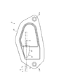
- FIG. 1 shows a grommet 2 according to the first embodiment.
- FIG. 2 shows an AA cross section in FIG.
- the two-dot chain line in the figure represents the control cable 1.
- control cable 1 will be briefly described.
- the long member in the present application refers to the control cable 1, particularly the outer casing 1o.
- the control cable 1 includes an inner cable 1i and an outer casing 1o that covers the inner cable 1i.
- the long member is not limited, and may be an inner cable 1i, a power transmission line, a communication line, or the like.
- a member having a predetermined length and disposed through the inside and the outside such as the inside and outside of the vehicle can be used, and the outer peripheral surface is preferably a smooth surface.
- the grommet 2 holds the control cable 1 in a state where the grommet 2 is attached to an automobile chassis panel or the like.
- the grommet 2 includes a main body portion 21 and an insertion portion 22 provided in the main body portion 21.
- the grommet 2 is made of an elastic material (such as ethylene / propylene / diene rubber (EPDM)).
- EPDM ethylene / propylene / diene rubber
- the material is not limited, and for example, nitrile rubber (NBR) or chloroprene rubber (CR) may be used.
- NBR nitrile rubber
- CR chloroprene rubber
- a material having elasticity may be combined with a part of the material having no elasticity.
- the insertion part 22 made of rubber may be baked on the main body part 21 made of metal.
- the elastic member may be an elastic member that has an elastic function and can be in close contact with the outer casing 1o, which is a long member. Since the control cable 1 is inserted by covering the outer periphery of the long member, a sealing structure is provided. Can be formed.
- the main body 21 refers to a wide and flat portion of the grommet 2.
- the main body 21 is formed in a polygonal shape and closes a cable hole provided in the chassis panel. Further, the main body portion 21 is provided with two bolt holes 21h, and is fixed to the chassis panel by bolts passed through the bolt holes 21h.
- the insertion portion 22 is a portion through which the long member is inserted, and includes a portion where the tubular portion 23 in the grommet 2 is formed in the present embodiment.
- the cylindrical portion 23 is formed with an insertion hole 23h at the center thereof, and has a predetermined thickness that can be held, and thus holds the control cable 1 routed up to the cable hole.
- the insertion hole 23 h is provided with a seal portion 24 on the inner wall, and the control cable 1 is sealed by the seal portion 24.
- the insertion hole 23h is provided with a seal portion 24 on its inner wall, and the outer periphery of the outer casing 1o is sealed by the unevenness of the seal portion 24.
- FIG. 3 shows the insertion part 22 of the grommet 2.
- FIG. 4 shows the unevenness provided in the seal portion 24.
- the insertion portion 22 includes a portion where the cylindrical portion 23 in the grommet 2 is formed.
- the cylindrical portion 23 has openings 23o at both ends (see FIG. 2).
- the opening 23o is formed in a size that allows the control cable 1 to be inserted, and the shape is not particularly limited, but is circular in this embodiment.
- An insertion hole 23h is formed so as to communicate with both openings 23o. That is, the cylindrical part 23 has a shape in which the insertion hole 23h penetrates from one opening 23o to the other opening 23o.
- the insertion hole 23 h is provided with a seal portion 24 on the inner wall thereof, and the outer periphery of the outer casing 1 o is sealed by the unevenness of the seal portion 24.
- the seal portion 24 is provided with irregularities spaced apart in the axial direction, and by sealing the outer periphery of the outer casing 1o, the moisture is prevented from moving inward along the outer periphery of the outer casing 1o, Can exhibit waterproofness.
- the insertion hole 23h should just be provided so that the control cable 1 can be wired over the inside and outside of a vehicle, and is made into the cylindrical form in this embodiment.
- the concave and convex concave portion 24c is formed in an annular shape around the central axis L of the insertion hole 23h. These recesses 24c have the same depth.
- the concavo-convex convex portion 24p is formed in an annular shape around the central axis L of the insertion hole 23h.
- the heights of the convex portions 24p are not the same. That is, the convex part 24p in this grommet 2 has two types of convex part 24p with a high height, and convex part 24p with a low height.
- the convex portion 24p having a high height is defined as “first convex portion 25”
- the convex portion 24p having a low height is defined as “second convex portion 26”.
- the first convex portion 25 is in close contact with the control cable 1 and seals the control cable 1. That is, the first convex portion 25 seals moisture such as rainwater that travels through the outer casing 1 o by being in close contact with the outer casing 1 o of the control cable 1.
- the first convex portion 25 may have an insertion resistance that does not hinder the insertability of the outer casing 1o, which is a long member, and can also have a shape that can be in close contact with the outer shape of the outer casing 1o.
- the “close contact” means a state in which the pressure at the contact portion is increased by the elastically deformed first convex portion 25 pressing the outer periphery of the outer casing 1o strongly, and functionally, moisture such as rainwater is surely secured.
- the cross-sectional shape of the base part 25b is substantially rectangular shape.
- the cross-sectional shape of the top part 25a becomes the substantially wedge shape which becomes thin gradually as the center line L is approached. That is, the cross-sectional shape of the first convex portion 25 extends perpendicularly from the bottom surface of the concave portion 24c toward the central axis L, and gradually decreases from a predetermined height.
- the reason for this shape is to moderately suppress the rigidity at the base and reduce the contact area with the control cable 1. Thereby, the softness
- the inner diameter ⁇ x of the top portion 25a of the first convex portion 25 is between 99% and 65% with respect to the outer diameter ⁇ c of the control cable 1 (see FIG. 5).
- ⁇ x / ⁇ c ⁇ 100 99 to 65 (%)
- the ratio of the inner diameter ⁇ x to the outer diameter ⁇ c can be practically used in the range of 65% or more and 99% or less. However, in order to improve the workability while ensuring the sealing performance, the ratio should be 87% or more and 95% or less. Is preferred.
- the “top portion” means a portion of the first convex portion 25 that is near the top of the axial side of the portion projecting in the axial direction of the insertion hole 23 h, and this portion is the portion of the control cable 1. It is also a part which contacts the outer periphery of the outer casing 1o at the time of insertion, and causes the first convex part 25 to undergo elastic deformation. In the present embodiment, as described above, it is convex, and the reference of the inner diameter is based on the tip of the convex portion in both the first convex portion 25 and the second convex portion 26 described later.
- the second convex portion 26 comes into contact with the control cable 1 and seals the control cable 1. That is, the second convex portion 26 is in contact with the outer casing 1o of the control cable 1 to seal moisture such as rainwater transmitted through the outer casing 1o.
- “Abutting” refers to a state in which the pressure at the contact portion is slightly increased by the elastically deformed second convex portion 26 pressing the outer periphery of the outer casing 1 o weakly. A state in which moisture such as rain water can be supplementarily sealed while facilitating insertion.
- the 2nd convex part 26 has a role which seals water
- the first convex part 25 can ensure the sealing function, it does not necessarily have to be annular.
- the cross-sectional shape of the base part 26b is substantially rectangular shape.
- the cross-sectional shape of the top part 26a becomes the substantially wedge shape which becomes thin gradually as the center line L is approached. That is, the cross-sectional shape of the second convex portion 26 extends perpendicularly from the bottom surface of the concave portion 24c toward the central axis L, and gradually decreases from a predetermined height.
- the reason for this shape is to moderately suppress the rigidity at the base and reduce the contact area with the control cable 1. Thereby, the softness
- the flexibility of the second convex portion 26 can also be realized by deepening the concave portion 24c.
- the height from the bottom face of the recessed part 24c of the 2nd convex part 26 it has the height which can contact
- the inner diameter ⁇ y of the second convex portion 26 when the control cable 1 is inserted, it is provided so as not to cause resistance to insertion and to prevent elastic deformation.
- the inner diameter ⁇ y of the top 26a of the second convex portion 26 is between 100 percent and 92 percent with respect to the outer diameter ⁇ c of the control cable 1 (see FIG. 5).
- a numerical value is calculated by the following mathematical formula.
- Formula: ⁇ y / ⁇ c ⁇ 100 100 to 92 (%)
- the outer diameter ⁇ c of the outer casing 1 o is 7.1 mm
- the inner diameter ⁇ x of the first convex portion 25 is 6.4 mm
- the inner diameter ⁇ y of the second convex portion 26 Is 6.8 mm.
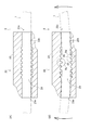
- FIG. 5 shows the insertion portion 22 before and after the control cable 1 is inserted.
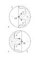
- FIG. 6 is an enlarged view of the region Ra and the region Rb in FIG.
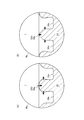
- FIG. 7 shows the insertion portion 22 before and after the control cable 1 is bent.
- FIG. 8 is an enlarged view of the region Rc and the region Rd in FIG. 6 and 8 indicate the deformation direction of the first convex portion 25 or the second convex portion 26.
- the inner diameter ⁇ x of the top portion 25 a of the first convex portion 25 is smaller than the outer diameter ⁇ c of the control cable 1.
- the inner diameter ⁇ y of the top portion 26 a of the second convex portion 26 is substantially the same as the outer diameter ⁇ c of the control cable 1. Therefore, the first convex portion 25 is deformed by the insertion of the control cable 1, and the second convex portion 26 is hardly deformed. For this reason, the first convex portion 25 becomes a resistance when the control cable 1 is inserted, but the second convex portion 26 hardly becomes a resistance.
- the first convex portion 25 and the second convex portion 26 in the grommet 2 are provided alternately, and the first convex portion 25 is disposed at an appropriate interval from the adjacent second convex portion 26. ing. For this reason, even if the first convex portion 25 is deformed by the insertion of the control cable 1, it does not interfere with the adjacent second convex portion 26. That is, even if the first convex portion 25 is deformed by the insertion of the control cable 1 and bulges or bends in the axial direction of the insertion hole 23h, the first convex portion 25 does not contact the adjacent second convex portion 26.
- the first convex portion 25 is easily deformed when the control cable 1 is inserted, and does not have a large resistance that hinders the insertion operation.
- the interval at which the first convex portion 25 and the second convex portion 26 do not interfere with each other is “the long member (control cable 1) is inserted. It is defined as “interval that can be inserted into the hole 23h”.
- the 1st convex part 25 is provided too densely, since it is also considered that the insertion resistance of the control cable 1 becomes large, according to the internal diameter (phi) x of the 1st convex part 25, a space
- the first convex portion 25 comes into close contact with the outer casing 1o of the control cable 1. Further, since the first convex portion 25 has a large amount of displacement before and after the insertion of the control cable 1, the allowance during expansion is large, and even if the control cable 1 is curved, a gap is hardly generated. That is, the first convex portion 25 is flexibly deformed according to the curved shape of the control cable 1 and is always in close contact with the outer casing 1 o of the control cable 1. More specifically, it can be seen that the first convex portion 25 in the region Rc extends according to the curvature of the control cable 1 and maintains a state of being in close contact with the control cable 1.
- the second convex portion 26 comes into contact with the outer casing 1o of the control cable 1. Further, since the second convex portion 26 has a small amount of displacement before and after the insertion of the control cable 1, a contraction margin at the time of contraction is large, and even if the control cable 1 is curved, a gap is hardly generated. That is, the second convex portion 26 is deformed flexibly according to the curved shape of the control cable 1, and always abuts on the outer casing 1 o of the control cable 1. More specifically, it can be seen that the second convex portion 26 in the region Rd is contracted in accordance with the curvature of the control cable 1 and is kept in contact with the control cable 1.
- the grommet 2 has an insertion portion 22.
- the insertion portion 22 includes a cylindrical portion 23 having openings 23o at both ends, an insertion hole 23h that communicates with both openings 23o and through which the control cable 1 is inserted, and a seal that seals the control cable 1 on the inner wall of the insertion hole 23h. Part 24.
- sticker part 24 is with respect to the control cable 1 penetrated by the 1st convex part 25 formed so that contact
- a second convex portion 26 formed so as to be able to contact the outer periphery of the control cable 1.
- the first convex portions 25 are arranged at intervals at which the control cable 1 can be inserted into the insertion holes 23h.
- the second convex portion 26 is disposed between the first convex portions 25.
- the second convex portion 26 is annular in the circumferential direction of the insertion hole 23h, and is formed such that the inner diameter ⁇ y at the top portion 26a is substantially the same as the outer diameter ⁇ c of the control cable 1.
- the first convex portion 25 is annular in the circumferential direction of the insertion hole 23 h, and the inner diameter ⁇ x at the top portion 25 a is smaller than the outer diameter ⁇ c of the control cable 1 and smaller than the inner diameter of the second convex portion 26. It is formed as follows.
- the inner diameter ⁇ y of the top portion 26 a of the second convex portion 26 is between 100 percent and 92 percent with respect to the outer diameter of the control cable 1.
- the grommet 2 can be easily inserted into the control cable 1 and the sealing performance is not deteriorated even if the control cable 1 is bent. That is, if the technical idea of the present invention is used, a long structure can be easily inserted, and a sealing structure in which the sealing performance does not deteriorate even when the long member is curved is realized.
- FIG. 9 shows the shape of the convex portion 24p of the grommet 2 according to another embodiment.
- the shapes of the first convex portion 25 and the second convex portion 26 are represented as one convex portion 24p.
- the cross-sectional shape of the base portion 25b is substantially rectangular (see FIG. 4). This is because the rigidity at the base is moderately suppressed and the flexibility is increased.
- the cross-sectional shape of the base portion 25b is not limited to a substantially rectangular shape.
- a substantially wedge shape that gradually decreases as it approaches the center line L may be used.
- the first convex portion 25 of the grommet 2 according to the first embodiment has a substantially wedge shape that gradually becomes thinner as the cross-sectional shape of the top portion 25a approaches the center line L (see FIG. 4). ).
- the cross-sectional shape of the top portion 25a is not limited to a substantially wedge shape.
- a substantially rectangular shape may be used.
- it can also be set as a substantially circular arc shape like (C).
- it can also be made into a substantially trapezoidal shape as shown in (D).
- work of this control cable 1 becomes easy by inserting the control cable 1 from the down side of an inclined surface to the up side.
- the cross-sectional shape of the base portion 26b is substantially rectangular (see FIG. 4). This is because the rigidity at the base is moderately suppressed and the flexibility is increased.
- the cross-sectional shape of the base portion 26b is not limited to a substantially rectangular shape.
- a substantially wedge shape that gradually decreases as it approaches the center line L may be used.
- the second convex portion 26 of the grommet 2 has a substantially wedge shape that gradually decreases as the cross-sectional shape of the top portion 26a approaches the center line L (see FIG. 4). ).
- the cross-sectional shape of the top portion 26a is not limited to a substantially wedge shape.
- a substantially rectangular shape may be used.
- it can also be set as a substantially circular arc shape like (C).
- it can also be made into a substantially trapezoidal shape as shown in (D).
- work of this control cable 1 becomes easy by inserting the control cable 1 from the down side of an inclined surface to the up side.
- FIG. 10 shows the unevenness provided in the seal portion 24 of the grommet 2 according to another embodiment.
- the first convex portion 25 and the second convex portion 26 of the grommet 2 according to the first embodiment are alternately provided (see FIG. 4). This is because all of the first convex portion 25 and the second convex portion 26 exhibit a stable function.
- the first convex portions 25 can be continuous.
- the 2nd convex part 26 shall be continuous.
- the second convex portion 26 is provided between the first convex portions 25, the first convex portion 25 and the second convex portion 26 are separated and the first convex portion 25 and the first convex portion 25 are separated. Even if each of the two convex portions 26 is provided continuously, it is sufficient that the second convex portion 26 is provided so as to exhibit an auxiliary sealing function, and the second convex portion 26 is the first convex portion. It is also possible to configure appropriately so as not to inhibit the elastic deformation of 25.
- Control cable (long member) 1i Inner cable 1o Outer casing 2 Grommet (elastic member) 21 Main body part 22 Insertion part 23 Cylindrical part 23h Insertion hole 24 Seal part 24c Concave part 24p Convex part 25 First convex part 26 Second convex part ⁇ x Inner diameter at the top part of the first convex part ⁇ y Inner diameter at the top part of the second convex part ⁇ c Outside diameter of control cable
Landscapes
- Engineering & Computer Science (AREA)
- General Engineering & Computer Science (AREA)
- Mechanical Engineering (AREA)
- Health & Medical Sciences (AREA)
- Oral & Maxillofacial Surgery (AREA)
- Gasket Seals (AREA)
- Installation Of Indoor Wiring (AREA)
- Insulating Bodies (AREA)
- Flexible Shafts (AREA)
- Cable Accessories (AREA)
Abstract
Description
数式:φx/φc×100=99~65(%)
外径φcに対する内径φxの割合は、65%以上99%以下の範囲で実用することができるが、シール性を確保しつつ作業性をより向上するために、87%以上95%以下とすることが好ましい。なお、「頂部」とは、第一凸部25の、挿通孔23hの軸方向へ張り出した部分のうちの最も軸側の頂点付近の部分を意味するものであり、この部分がコントロールケーブル1の挿通時にアウターケーシング1oの外周と接触して第一凸部25の弾性変形を生じさせる部分でもある。本実施形態においては、上述のように、凸状とされ、第一凸部25においても、後述の第二凸部26においても、内径の基準は凸状部分の先端を基準としている。
数式:φy/φc×100=100~92(%)
ここで、本実施形態においては、アウターケーシング1oの外径φcが7.1mmであるのに対して、第一凸部25の内径φxが6.4mmとされ、第二凸部26の内径φyが6.8mmとされている。
1i インナーケーブル
1o アウターケーシング
2 グロメット(弾性部材)
21 本体部
22 挿通部
23 筒状部
23h 挿通孔
24 シール部
24c 凹部
24p 凸部
25 第一凸部
26 第二凸部
φx 第一凸部の頂部における内径
φy 第二凸部の頂部における内径
φc コントロールケーブルの外径
Claims (4)
- 長尺部材と、前記長尺部材が挿通されて該長尺部材の外周に密着する挿通部を有する弾性部材と、を備えたシール構造であって、
前記挿通部は、両端に開口を備えた筒状部と、両開口と連通して前記長尺部材が挿通される挿通孔と、前記挿通孔の内壁において前記長尺部材をシールするシール部と、を備え、
前記シール部は、前記挿通孔に挿通された前記長尺部材に対して周周り方向に密着可能に形成された第一凸部と、
前記挿通孔に挿通された前記長尺部材に対して該長尺部材の外周と当接可能に形成された第二凸部と、を有している、ことを特徴とするシール構造。 - 前記第一凸部は、前記長尺部材が前記挿通孔に挿通可能な間隔で配置され、
前記第二凸部は、前記第一凸部の間に配置されている、ことを特徴とする請求項1に記載のシール構造。 - 前記第二凸部は、前記挿通孔の周周り方向に環状であり、頂部における内径が前記長尺部材の外径とほぼ同一となるように形成され、
前記第一凸部は、前記挿通孔の周周り方向に環状であり、頂部における内径が前記長尺部材の外径よりも小さく、かつ前記第二凸部の内径よりも小さくなるように形成されている、ことを特徴とする請求項1又は請求項2に記載のシール構造。 - 前記第二凸部の頂部における内径は、前記長尺部材の外径に対して100パーセントから92パーセントの間にある、ことを特徴とする請求項1から請求項3のいずれか一項に記載のシール構造。
Priority Applications (5)
| Application Number | Priority Date | Filing Date | Title |
|---|---|---|---|
| MX2017000572A MX382170B (es) | 2014-07-28 | 2015-07-27 | Estructura de sello. |
| US15/329,325 US9909612B2 (en) | 2014-07-28 | 2015-07-27 | Seal structure |
| RU2017102504A RU2650229C1 (ru) | 2014-07-28 | 2015-07-27 | Уплотнительная конструкция |
| CN201580029135.3A CN106461080A (zh) | 2014-07-28 | 2015-07-27 | 密封构造 |
| BR112017000965-0A BR112017000965B1 (pt) | 2014-07-28 | 2015-07-27 | Estrutura de vedação |
Applications Claiming Priority (2)
| Application Number | Priority Date | Filing Date | Title |
|---|---|---|---|
| JP2014153367A JP6220320B2 (ja) | 2014-07-28 | 2014-07-28 | シール構造 |
| JP2014-153367 | 2014-07-28 |
Publications (1)
| Publication Number | Publication Date |
|---|---|
| WO2016017565A1 true WO2016017565A1 (ja) | 2016-02-04 |
Family
ID=55217466
Family Applications (1)
| Application Number | Title | Priority Date | Filing Date |
|---|---|---|---|
| PCT/JP2015/071193 Ceased WO2016017565A1 (ja) | 2014-07-28 | 2015-07-27 | シール構造 |
Country Status (7)
| Country | Link |
|---|---|
| US (1) | US9909612B2 (ja) |
| JP (1) | JP6220320B2 (ja) |
| CN (1) | CN106461080A (ja) |
| BR (1) | BR112017000965B1 (ja) |
| MX (1) | MX382170B (ja) |
| RU (1) | RU2650229C1 (ja) |
| WO (1) | WO2016017565A1 (ja) |
Cited By (1)
| Publication number | Priority date | Publication date | Assignee | Title |
|---|---|---|---|---|
| CN106122244A (zh) * | 2016-06-24 | 2016-11-16 | 柳州聚龙科技有限公司 | 刹车线八角环 |
Families Citing this family (2)
| Publication number | Priority date | Publication date | Assignee | Title |
|---|---|---|---|---|
| CN107806467B (zh) * | 2017-10-19 | 2019-07-19 | 江阴市蒋氏汽摩部件有限公司 | 一种防水拉索 |
| JP7695867B2 (ja) * | 2021-11-25 | 2025-06-19 | 株式会社ヨコオ | アンテナ装置 |
Citations (3)
| Publication number | Priority date | Publication date | Assignee | Title |
|---|---|---|---|---|
| JP2009068518A (ja) * | 2007-09-10 | 2009-04-02 | Hi-Lex Corporation | グロメットアッセンブリ |
| JP2011185294A (ja) * | 2010-03-04 | 2011-09-22 | Yazaki Corp | シール部材及びシール構造 |
| JP2011190834A (ja) * | 2010-03-12 | 2011-09-29 | Nok Corp | 配水管継手の密封構造 |
Family Cites Families (10)
| Publication number | Priority date | Publication date | Assignee | Title |
|---|---|---|---|---|
| US5409337A (en) * | 1993-09-02 | 1995-04-25 | Eaton Corporation | Retained seal assembly |
| RU2103775C1 (ru) * | 1996-08-14 | 1998-01-27 | Владимир Петрович Рыдловский | Кабельный проход и способ монтажа кабельного прохода |
| JP3835791B2 (ja) * | 2000-11-15 | 2006-10-18 | 矢崎総業株式会社 | グロメット |
| JP2005069166A (ja) * | 2003-08-27 | 2005-03-17 | Honda Motor Co Ltd | プラグチューブシール取付構造 |
| JP5126999B2 (ja) * | 2008-03-13 | 2013-01-23 | 日本バルカー工業株式会社 | シール材 |
| FR2937112B1 (fr) * | 2008-10-13 | 2010-11-12 | Amphenol Air Lb | Dispositif de maintien etanche d'une conduite, procede de montage etanche d'une conduite a travers une cloison et utilisation d'un tel dispositif pour la traversee etanche d'une cloison d'un reservoir d'aeronef |
| JP2012112397A (ja) * | 2010-11-19 | 2012-06-14 | Aisin Seiki Co Ltd | 圧入部材の取付構造 |
| JP5644698B2 (ja) * | 2011-06-24 | 2014-12-24 | 住友電装株式会社 | グロメット |
| WO2013065701A1 (ja) * | 2011-10-31 | 2013-05-10 | 株式会社ハイレックスコーポレーション | シール構造 |
| US9403433B1 (en) * | 2015-03-30 | 2016-08-02 | Nissan North America, Inc. | Shifter cable assembly of a vehicle |
-
2014
- 2014-07-28 JP JP2014153367A patent/JP6220320B2/ja active Active
-
2015
- 2015-07-27 US US15/329,325 patent/US9909612B2/en active Active
- 2015-07-27 WO PCT/JP2015/071193 patent/WO2016017565A1/ja not_active Ceased
- 2015-07-27 CN CN201580029135.3A patent/CN106461080A/zh active Pending
- 2015-07-27 RU RU2017102504A patent/RU2650229C1/ru active
- 2015-07-27 BR BR112017000965-0A patent/BR112017000965B1/pt active IP Right Grant
- 2015-07-27 MX MX2017000572A patent/MX382170B/es unknown
Patent Citations (3)
| Publication number | Priority date | Publication date | Assignee | Title |
|---|---|---|---|---|
| JP2009068518A (ja) * | 2007-09-10 | 2009-04-02 | Hi-Lex Corporation | グロメットアッセンブリ |
| JP2011185294A (ja) * | 2010-03-04 | 2011-09-22 | Yazaki Corp | シール部材及びシール構造 |
| JP2011190834A (ja) * | 2010-03-12 | 2011-09-29 | Nok Corp | 配水管継手の密封構造 |
Cited By (1)
| Publication number | Priority date | Publication date | Assignee | Title |
|---|---|---|---|---|
| CN106122244A (zh) * | 2016-06-24 | 2016-11-16 | 柳州聚龙科技有限公司 | 刹车线八角环 |
Also Published As
| Publication number | Publication date |
|---|---|
| US9909612B2 (en) | 2018-03-06 |
| BR112017000965B1 (pt) | 2021-11-30 |
| MX382170B (es) | 2025-03-13 |
| US20170204896A1 (en) | 2017-07-20 |
| JP2016031103A (ja) | 2016-03-07 |
| CN106461080A (zh) | 2017-02-22 |
| BR112017000965A2 (pt) | 2017-11-21 |
| RU2650229C1 (ru) | 2018-04-11 |
| MX2017000572A (es) | 2017-05-01 |
| JP6220320B2 (ja) | 2017-10-25 |
Similar Documents
| Publication | Publication Date | Title |
|---|---|---|
| JP5387541B2 (ja) | グロメット | |
| US8981228B2 (en) | Grommet for wire harness | |
| JP5692504B2 (ja) | ガスケット | |
| WO2014024785A1 (ja) | グロメット | |
| JP6220320B2 (ja) | シール構造 | |
| JP5469585B2 (ja) | ワイヤハーネス用のグロメット | |
| JP2011188619A (ja) | ワイヤハーネス用のグロメット | |
| JP6353344B2 (ja) | シール構造及びコントロールケーブルユニット | |
| CN214412142U (zh) | 电缆管道孔封堵装置 | |
| JP4352179B2 (ja) | 樹脂管接続継手 | |
| JP2012067555A (ja) | ライニング体及びそれを用いたライニング構造物 | |
| JP6331210B2 (ja) | パッキンを備えた水洗便器 | |
| JP4845536B2 (ja) | 管端面の防食構造 | |
| US20250286356A1 (en) | Waterproof structure and wire harness | |
| JP5862543B2 (ja) | グロメット及びワイヤーハーネス | |
| JP6812150B2 (ja) | 留め具 | |
| JP2017072159A (ja) | ボールジョイント用ダストカバー | |
| JPH01188789A (ja) | 可とう自在なケーブル保護鋼管 | |
| JP3187116U (ja) | 推進管 | |
| CN214412144U (zh) | 一种电缆管道孔封堵装置 | |
| JP7763313B2 (ja) | コルゲート装着構造 | |
| JP7049372B2 (ja) | パイプ・クランプ用の封止スリーブおよびかかる封止スリーブを有するパイプ・クランプ | |
| KR20170002143U (ko) | 대구경 스파이럴 와운드 가스켓 구조 | |
| JP6505467B2 (ja) | グロメット | |
| JP2006070569A (ja) | 可撓性継手のリブ付管用締付けリング構造 |
Legal Events
| Date | Code | Title | Description |
|---|---|---|---|
| 121 | Ep: the epo has been informed by wipo that ep was designated in this application |
Ref document number: 15827056 Country of ref document: EP Kind code of ref document: A1 |
|
| WWE | Wipo information: entry into national phase |
Ref document number: MX/A/2017/000572 Country of ref document: MX |
|
| WWE | Wipo information: entry into national phase |
Ref document number: 15329325 Country of ref document: US |
|
| NENP | Non-entry into the national phase |
Ref country code: DE |
|
| REG | Reference to national code |
Ref country code: BR Ref legal event code: B01A Ref document number: 112017000965 Country of ref document: BR |
|
| ENP | Entry into the national phase |
Ref document number: 2017102504 Country of ref document: RU Kind code of ref document: A |
|
| 122 | Ep: pct application non-entry in european phase |
Ref document number: 15827056 Country of ref document: EP Kind code of ref document: A1 |
|
| ENP | Entry into the national phase |
Ref document number: 112017000965 Country of ref document: BR Kind code of ref document: A2 Effective date: 20170117 |