WO2016017465A1 - ガス発生器 - Google Patents
ガス発生器 Download PDFInfo
- Publication number
- WO2016017465A1 WO2016017465A1 PCT/JP2015/070635 JP2015070635W WO2016017465A1 WO 2016017465 A1 WO2016017465 A1 WO 2016017465A1 JP 2015070635 W JP2015070635 W JP 2015070635W WO 2016017465 A1 WO2016017465 A1 WO 2016017465A1
- Authority
- WO
- WIPO (PCT)
- Prior art keywords
- peripheral wall
- wall surface
- cup
- cup member
- cylindrical member
- Prior art date
- Legal status (The legal status is an assumption and is not a legal conclusion. Google has not performed a legal analysis and makes no representation as to the accuracy of the status listed.)
- Ceased
Links
Images


Classifications
-
- B—PERFORMING OPERATIONS; TRANSPORTING
- B60—VEHICLES IN GENERAL
- B60R—VEHICLES, VEHICLE FITTINGS, OR VEHICLE PARTS, NOT OTHERWISE PROVIDED FOR
- B60R21/00—Arrangements or fittings on vehicles for protecting or preventing injuries to occupants or pedestrians in case of accidents or other traffic risks
- B60R21/02—Occupant safety arrangements or fittings, e.g. crash pads
- B60R21/16—Inflatable occupant restraints or confinements designed to inflate upon impact or impending impact, e.g. air bags
- B60R21/26—Inflatable occupant restraints or confinements designed to inflate upon impact or impending impact, e.g. air bags characterised by the inflation fluid source or means to control inflation fluid flow
- B60R21/264—Inflatable occupant restraints or confinements designed to inflate upon impact or impending impact, e.g. air bags characterised by the inflation fluid source or means to control inflation fluid flow using instantaneous generation of gas, e.g. pyrotechnic
- B60R21/2644—Inflatable occupant restraints or confinements designed to inflate upon impact or impending impact, e.g. air bags characterised by the inflation fluid source or means to control inflation fluid flow using instantaneous generation of gas, e.g. pyrotechnic using only solid reacting substances, e.g. pellets, powder
-
- B—PERFORMING OPERATIONS; TRANSPORTING
- B01—PHYSICAL OR CHEMICAL PROCESSES OR APPARATUS IN GENERAL
- B01J—CHEMICAL OR PHYSICAL PROCESSES, e.g. CATALYSIS OR COLLOID CHEMISTRY; THEIR RELEVANT APPARATUS
- B01J7/00—Apparatus for generating gases
-
- B—PERFORMING OPERATIONS; TRANSPORTING
- B60—VEHICLES IN GENERAL
- B60R—VEHICLES, VEHICLE FITTINGS, OR VEHICLE PARTS, NOT OTHERWISE PROVIDED FOR
- B60R21/00—Arrangements or fittings on vehicles for protecting or preventing injuries to occupants or pedestrians in case of accidents or other traffic risks
- B60R21/02—Occupant safety arrangements or fittings, e.g. crash pads
- B60R21/16—Inflatable occupant restraints or confinements designed to inflate upon impact or impending impact, e.g. air bags
- B60R21/26—Inflatable occupant restraints or confinements designed to inflate upon impact or impending impact, e.g. air bags characterised by the inflation fluid source or means to control inflation fluid flow
- B60R2021/26029—Ignitors
-
- B—PERFORMING OPERATIONS; TRANSPORTING
- B60—VEHICLES IN GENERAL
- B60R—VEHICLES, VEHICLE FITTINGS, OR VEHICLE PARTS, NOT OTHERWISE PROVIDED FOR
- B60R21/00—Arrangements or fittings on vehicles for protecting or preventing injuries to occupants or pedestrians in case of accidents or other traffic risks
- B60R21/02—Occupant safety arrangements or fittings, e.g. crash pads
- B60R21/16—Inflatable occupant restraints or confinements designed to inflate upon impact or impending impact, e.g. air bags
- B60R21/26—Inflatable occupant restraints or confinements designed to inflate upon impact or impending impact, e.g. air bags characterised by the inflation fluid source or means to control inflation fluid flow
- B60R21/264—Inflatable occupant restraints or confinements designed to inflate upon impact or impending impact, e.g. air bags characterised by the inflation fluid source or means to control inflation fluid flow using instantaneous generation of gas, e.g. pyrotechnic
- B60R2021/2642—Inflatable occupant restraints or confinements designed to inflate upon impact or impending impact, e.g. air bags characterised by the inflation fluid source or means to control inflation fluid flow using instantaneous generation of gas, e.g. pyrotechnic comprising a plurality of combustion chambers or sub-chambers
-
- B—PERFORMING OPERATIONS; TRANSPORTING
- B60—VEHICLES IN GENERAL
- B60R—VEHICLES, VEHICLE FITTINGS, OR VEHICLE PARTS, NOT OTHERWISE PROVIDED FOR
- B60R21/00—Arrangements or fittings on vehicles for protecting or preventing injuries to occupants or pedestrians in case of accidents or other traffic risks
- B60R21/02—Occupant safety arrangements or fittings, e.g. crash pads
- B60R21/16—Inflatable occupant restraints or confinements designed to inflate upon impact or impending impact, e.g. air bags
- B60R21/26—Inflatable occupant restraints or confinements designed to inflate upon impact or impending impact, e.g. air bags characterised by the inflation fluid source or means to control inflation fluid flow
- B60R21/264—Inflatable occupant restraints or confinements designed to inflate upon impact or impending impact, e.g. air bags characterised by the inflation fluid source or means to control inflation fluid flow using instantaneous generation of gas, e.g. pyrotechnic
- B60R21/2644—Inflatable occupant restraints or confinements designed to inflate upon impact or impending impact, e.g. air bags characterised by the inflation fluid source or means to control inflation fluid flow using instantaneous generation of gas, e.g. pyrotechnic using only solid reacting substances, e.g. pellets, powder
- B60R2021/2648—Inflatable occupant restraints or confinements designed to inflate upon impact or impending impact, e.g. air bags characterised by the inflation fluid source or means to control inflation fluid flow using instantaneous generation of gas, e.g. pyrotechnic using only solid reacting substances, e.g. pellets, powder comprising a plurality of combustion chambers or sub-chambers
-
- B—PERFORMING OPERATIONS; TRANSPORTING
- B60—VEHICLES IN GENERAL
- B60R—VEHICLES, VEHICLE FITTINGS, OR VEHICLE PARTS, NOT OTHERWISE PROVIDED FOR
- B60R21/00—Arrangements or fittings on vehicles for protecting or preventing injuries to occupants or pedestrians in case of accidents or other traffic risks
- B60R21/02—Occupant safety arrangements or fittings, e.g. crash pads
- B60R21/16—Inflatable occupant restraints or confinements designed to inflate upon impact or impending impact, e.g. air bags
- B60R21/26—Inflatable occupant restraints or confinements designed to inflate upon impact or impending impact, e.g. air bags characterised by the inflation fluid source or means to control inflation fluid flow
- B60R21/261—Inflatable occupant restraints or confinements designed to inflate upon impact or impending impact, e.g. air bags characterised by the inflation fluid source or means to control inflation fluid flow with means other than bag structure to diffuse or guide inflation fluid
Definitions
- the present invention relates to a gas generator used in an airbag device mounted on an automobile.
- a pyrotechnic gas generator using a gas generating agent is one in which a combustion chamber filled with a gas generating agent is separated by disposing a partition in a housing.
- the partition wall is formed with a through hole for communicating the inside and the outside surrounded by the partition wall.
- a cylinder member or a combination of a cylinder member and a lid member is used as the partition wall.
- US-B No. 7374204 is an invention of an inflator for an airbag device, and describes an inflator having two combustion chambers.
- 3 shows a state before the operation
- FIG. 4 shows a state where only the first igniter 50 is operated
- FIG. 5 shows a state where both the first igniter 50 and the second igniter 58 are operated. is there.
- the second chamber 112 is formed by a combination of a combustion cup 110 and a cap 120 disposed in the housing 70.
- the cap 120 has a through hole 124, but is closed by the peripheral wall surface of the combustion cup 110 before operation (FIG. 3).
- both the first igniter 50 and the second igniter 58 are actuated (FIG. 5)
- the cap 120 moves to the upper wall 72 side due to an increase in the pressure in the second chamber 112
- the closed through hole 124 is opened.
- DISCLOSURE OF THE INVENTION Invention 1 of the present invention comprises: A gas generator having two combustion chambers in a housing having a gas outlet, The two combustion chambers are separated into an inner combustion chamber inside a combustion chamber cup disposed in the housing and an outer combustion chamber outside.
- the combustion chamber cup is a combination of a cup member and a cylindrical member,
- the cup member has a drop-off preventing slit formed in the axial direction from the first end on the bottom surface side to the second end on the opening side on the peripheral wall surface;
- the cylindrical member has a protrusion whose first end opening is fixed to the bottom plate side of the housing and protrudes radially outward on the peripheral wall surface;
- the peripheral wall surface of the cup member has a plurality of through holes formed in the circumferential direction,
- the cup member and the tubular member are The cup member is covered on the second end opening side of the cylindrical member, and the cup member bottom surface is located on the housing top plate side, When the projection of the cylindrical member is fitted on the first end side of the drop-off prevention slit, the peripheral wall surface of the cylindrical member and the peripheral wall surface of the cup member are in direct contact with each other in the radial direction.
- the through hole is closed, In operation, the cup member is stopped by moving in the axial direction until the protrusion on the first end side of the drop-off preventing slit contacts the second end side, and the through hole of the cup member is opened.
- a gas generator is provided.
- Invention 2 of the present invention also provides A gas generator having two combustion chambers in a housing having a gas outlet, The two combustion chambers are separated into an inner combustion chamber inside a combustion chamber cup disposed in the housing and an outer combustion chamber outside.
- the combustion chamber cup is a combination of a cup member and a cylindrical member,
- the cup member has a drop-off preventing slit formed in the axial direction from the first end on the bottom surface side to the second end on the opening side on the peripheral wall surface;
- the cylindrical member has a protrusion whose first end opening is fixed to the bottom plate side of the housing and protrudes radially outward on the peripheral wall surface;
- the peripheral wall surface of the cylindrical member has a plurality of through holes formed in the circumferential direction,
- the cup member and the tubular member are The cup member is covered on the second end opening side of the cylindrical member, and the cup member bottom surface is located on the housing top plate side, When the projection of the cylindrical member is fitted on the first end side of the drop-off prevention s
- the through hole is closed, In operation, the cup member is stopped by moving in the axial direction until the protrusion on the first end side of the drop-off preventing slit contacts the second end side, and the through hole of the cylindrical member is opened.
- a gas generator is provided.
- invention 3 of the present invention provides A gas generator having two combustion chambers in a housing having a gas outlet, The two combustion chambers are separated into an inner combustion chamber inside a combustion chamber cup disposed in the housing and an outer combustion chamber outside.
- the combustion chamber cup is a combination of a cup member and a cylindrical member,
- the cup member has a drop-off preventing slit formed in the axial direction from the first end on the bottom surface side to the second end on the opening side on the peripheral wall surface;
- the cylindrical member has a protrusion whose first end opening is fixed to the bottom plate side of the housing and protrudes radially outward on the peripheral wall surface;
- Both of the peripheral wall surface of the cup member and the peripheral wall surface of the cylindrical member have a plurality of through holes formed in the circumferential direction,
- the cup member and the tubular member are The cup member is covered on the second end opening side of the cylindrical member, and the cup member bottom surface is located on the housing top plate side, When the projection of the cylindrical member is fitted on the first end
- the through hole is closed, During operation, the cup member is stopped by moving in the axial direction until the protrusion on the first end side of the drop-off preventing slit contacts the second end side, and the through hole of the cup member and the cylindrical member A gas generator is provided in which both through holes are opened.
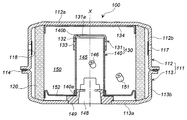
- FIG. 1 is a cross-sectional view of the gas generator of the present invention in the direction of the axis X.
- 2A is a perspective view of the cup member of the combustion chamber cup in FIG. 2A
- FIG. 2B is a perspective view of the cup member of the combustion chamber cup of another embodiment in FIG. 3A
- FIG. 3B is a perspective view of a cylinder member of a combustion chamber cup of another embodiment in FIG. 3B
- FIG. It is a perspective view of a member.
- FIG. 1 is a cross-sectional view of the gas generator of the present invention in the direction of the axis X.
- 2A is a perspective view of the cup member of the combustion chamber cup in FIG. 2A
- FIG. 2B is a perspective view of the cup member of the combustion chamber cup of another embodiment in FIG. 3A
- FIG. 3B is a perspective view of a cylinder member of a combustion chamber cup of another embodiment in FIG. 3B
- FIG. It is a perspective view of a
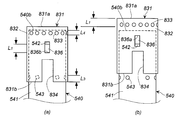
- FIG. 4 is a perspective view of a combustion chamber cup in which a cup member with a through hole and a cylindrical member without a through hole are combined, where (a) shows before operation and (b) shows after operation.
- FIG. 5 is a front view of (a) and (b) of FIG.
- FIG. 6 is a cross-sectional view in the direction of the axis X of a gas generator according to another embodiment of the present invention.
- FIG. 7 is a front view of a combustion chamber cup in which a cup member without a through-hole and a cylindrical member with a through-hole are combined, where (a) shows before operation and (b) shows after operation.
- FIG. 8 is a front view of an embodiment different from FIG. 7, (a) shows before operation, and (b) shows after operation.
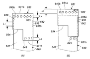
- FIG. 9 is a front view of a combustion chamber cup in which a cup member having a through hole and a cylindrical member having a through hole are combined, where (a) shows before operation and (b) shows after operation.
- FIG. 10 is a front view of an embodiment different from FIG. 9, (a) shows before operation, and (b) shows after operation.
- FIG. 11 is a front view of another embodiment different from FIG. 9, (a) shows before operation, and (b) shows after operation.
- FIG. 12 is a front view of another embodiment different from FIG. 9, (a) shows before operation, and (b) shows after operation.
- the through hole 124 is formed near the bottom surface of the cap 120, and the length from the through hole 124 to the opening of the cap 120 (for the sake of explanation, the “length L”) Is larger).
- the housing 70 receives an increase in internal pressure, and the upper wall 72 and the lower wall 74 of the housing 70 are deformed in the axial direction. There is a risk of falling off.
- the cap 120 is dropped from the combustion cup 110, it opens beyond the opening area defined by the through hole 124, and the pressure in the second chamber 112 changes (decreases), so that the gas generating agent 61 filled inside is filled.
- the present invention provides a gas generator that can maintain operation reliability and can be reduced in weight.
- the gas generator of the present invention has two combustion chambers, and the two combustion chambers are separated by a combustion chamber cup disposed in the housing.
- the combustion chamber cup is one in which one of the openings at both ends of the cylinder is closed, and is composed of a combination of a cylinder member and a cup member.
- the combination of the cylindrical member and the cup member in the present invention is described in US-B No. This corresponds to the combination of the combustion cup 110 and the cap 120 in the invention of FIG. 7374204 (FIGS. 3 to 5).
- the combination of the cylindrical member and the cup member in the present invention has a combination of a protrusion provided on the cylindrical member and a drop-off preventing slit provided on the cup member. This is clearly different from the invention of 7374204.
- the cylindrical member has a protrusion protruding outward in the radial direction on the peripheral wall surface.
- the protrusion may be a part of the cylindrical member deformed, or may be a member to which another member is fixed.
- the drop-off prevention slit formed on the peripheral wall surface of the cup member has a width and a shape capable of fitting the protrusion.
- the drop-off prevention slit may be an open slit formed continuously from the opening or a closed slit that is not connected to the opening as long as it forms a surface that contacts the protrusion.
- the peripheral wall surface of the cup member of invention 1 of the present invention has a plurality of through holes formed in the circumferential direction.
- the through-hole is a combustion gas outlet from the combustion chamber inside the combustion chamber cup and serves as a communication hole with the combustion chamber outside the combustion chamber cup.
- the projection of the cylindrical member is located on the first end side of the drop-off preventing slit of the cup member.
- the through hole of the cup member is closed from the inside.
- the cup member is moved so that the protrusion on the first end side of the drop-off preventing slit is positioned in the second end side direction in response to the increase in internal pressure, and the second end hits the protrusion. To stop moving.
- the through hole of the cup member appears above the second end opening of the cylindrical member and is opened, but the peripheral wall surface on the opening side of the cup member and the periphery on the second end opening side of the cylindrical member.
- the wall surfaces are in contact with each other, and protrusions are fitted into the drop-off prevention slits. For this reason, even when the housing is deformed in the axial direction during operation, there is no possibility that the cup member will fall off. Since the above-described “length L” in the invention of FIG. 7374204 (FIGS. 3 to 5) can be reduced, the weight can be further reduced.
- the combustion chamber cup is composed of a combination of a cup member and a cylindrical member, as in the first aspect, but the peripheral wall surface of the cylindrical member has a plurality of through holes formed in the circumferential direction. However, it is different that the peripheral wall surface of the cup member does not have a plurality of through holes formed in the circumferential direction.
- the through-hole is a combustion gas outlet from the combustion chamber inside the combustion chamber cup and serves as a communication hole with the combustion chamber outside the combustion chamber cup.
- the projection of the cylindrical member is located on the first end side of the drop-off prevention slit of the cup member.
- the through hole of the cylindrical member is closed from the outside.
- the cup member is moved so that the protrusion on the first end side of the drop-off preventing slit is positioned in the second end side direction in response to the increase in internal pressure, and the second end hits the protrusion. To stop moving.
- the combustion chamber cup is composed of a combination of a cup member and a cylindrical member as in each of the inventions 1 and 2, but both the peripheral wall surface of the cup member and the peripheral wall surface of the cylindrical member are circumferential.
- the difference is that it has a plurality of through holes formed in the direction.
- the through-hole is a combustion gas outlet from the combustion chamber inside the combustion chamber cup and serves as a communication hole with the combustion chamber outside the combustion chamber cup.
- the projection of the cylindrical member is located on the first end side of the drop-off prevention slit of the cup member.
- the through hole of the cup member is closed from the inside, and the through hole of the cylindrical member is closed from the outside.
- the cup member is moved so that the protrusion on the first end side of the drop-off preventing slit is positioned in the second end side direction in response to the increase in internal pressure, and the second end hits the protrusion. To stop moving.
- the through hole of the cup member appears above and opens the second opening of the cylindrical member, and the through hole of the cylindrical member appears below and opens the opening of the cup member.
- combustion gas is injected from the height position where an axial direction differs, concentration of the gas injection to an outer combustion chamber can be avoided.
- the peripheral wall surface on the opening side of the cup member and the peripheral wall surface on the second end opening side of the cylindrical member are in contact with each other, and a protrusion is fitted in the drop-off prevention slit. For this reason, even if it is a case where a housing deform
- the protrusion protruding radially outward from the peripheral wall surface of the cylindrical member is cut off at two locations in the axial direction with the peripheral wall surface of the second end opening spaced apart in the peripheral direction. It can be folded. Since the projection is formed by cutting and bending a part of the cylindrical member, the projection is easy and there is no increase in mass due to the formation of the projection.
- the protrusion protruding radially outward from the peripheral wall surface of the cylindrical member is cut in the axial direction of the peripheral wall surface of the second opening, and further bent in the peripheral direction.
- the projection is formed by cutting and bending a part of the cylindrical member, the projection is easy and there is no increase in mass due to the formation of the projection. Furthermore, the drag force against the force from the axial direction (first end opening side) increases.
- the protrusion protruding radially outward from the peripheral wall surface of the cylindrical member may be a protrusion of another member fixed to the peripheral wall surface.
- the protrusions of the separate members are used in this way, the protrusions can be formed at desired positions on the peripheral wall surface, and thus the positional relationship with the drop-off preventing slit can be easily adjusted.
- the cup member is In addition to the drop-off prevention slit formed in the axial direction from the first end on the bottom side to the second end on the opening side, A connection slit formed in the circumferential direction from the second end of the drop-off prevention slit; It can have an introduction slit formed from the connection slit to the opening.
- the drop-off prevention slit is an open system slit communicated with the outside of the cup member via the connection slit and the introduction slit. For this reason, when the protrusion is fitted into the drop-off prevention slit, the protrusion can be fitted into the drop-off prevention slit after passing the protrusion from the opening of the cup member through the introduction slit and the connection slit.
- the width of the introduction slit and the connection slit is preferably larger than the width of the protrusion in order to facilitate the introduction and movement of the protrusion.
- the gas generator of the present invention comprises:
- the drop-off prevention slit of the cup member is formed in the axial direction from the first end portion on the bottom surface side to the second end portion on the opening portion side on the peripheral wall surface, and the second end portion does not reach the opening portion.
- the peripheral wall surface of the cup member has a cut-out portion in which a part without the drop-off prevention slit and the through-hole is cut off,
- the cut-out portion is a combination of a first cut-out portion in which a part of the peripheral wall surface including the opening is cut out, and a second cut-out portion in which a part of the peripheral wall surface facing the first cut-out portion in the radial direction is cut off.
- the cup member has a through hole.
- the drop-off prevention slit is a closed slit that is not connected to the opening of the cup member. For this reason, when the drop-off prevention slit is fitted into the protrusion of the cylindrical member, the fitting work is facilitated if the cup member can be fitted so that the opening of the cup member is pushed outward.
- the cup member can be made of a metal such as flexible stainless steel or aluminum, and the above-described cut-out portion can be formed.
- the shapes of the first cutout portion and the second cutout portion are not particularly limited, but the peripheral wall surface including the opening has a shape such as a square, a rectangle, a trapezoid, or a partial circle (for example, a semicircle). What was cut off is preferable.
- the opening of the cup member can be easily expanded outward in the radial direction, and therefore, the cup member can be easily fitted into the protrusion of the cylindrical member.
- the gas generator of the present invention comprises: At least the peripheral wall surface of the cylindrical member has a plurality of through holes formed in the circumferential direction,
- the peripheral wall surface of the cup member has one or two or more cut-out portions where a part not facing the through hole of the cylindrical member in the thickness direction is cut off,
- the cut portion may be a portion of the peripheral wall surface including the opening of the cup member.
- the tubular member is a gas generator having a through hole
- the cup member may have a through hole or may not have a through hole.
- Good By forming a cut portion in which a portion of the cup member that is not directly facing the through hole of the cylindrical member in the thickness direction is cut, the entire combustion chamber cup including the cup member can be reduced in weight.
- the shape of the cut-out portion is not particularly limited, but it is preferable that the peripheral wall surface including the opening is cut into a shape such as a square, a rectangle, a trapezoid, or a partial circle (for example, a semicircle). US-B No. In the case of the embodiment shown in FIGS.
- the gas generator of the present invention is a combination of a cup member and a cylindrical member as a combustion chamber cup for separating two combustion chambers, and has a movement restricting means in the axial direction of the cup member during operation. I am using something. For this reason, the reliability of the operation can be improved, and the weight can be reduced by using the movement restricting means.
- FIG. 1 The gas generator 10 shown in FIG. This is the same as FIG. 1 of 2011-207326 except for a part.
- JP-A No. In FIG. 1 of 2011-207326, the combination of the second combustion chamber cup 41 and the cup-shaped cover member 50 is provided, but in FIG. 1 of the present invention, instead of the combination, the cup member 131 and the cylindrical member 140 are combined.
- a second combustion chamber cup 130 is used.
- the outer side of the second combustion chamber cup 130 composed of the cup member 131 and the cylindrical member 140 is the first combustion chamber (outer combustion chamber) 31, and the inner side is the second combustion chamber (inner combustion chamber) 46.
- JP-A No. There is no retainer 60 in FIG. 1 of 2011-207326.
- the diffuser shell 12 and the closure shell 13 are welded at the joint 15 to form a housing 11 serving as an outer container.
- a plurality of gas discharge ports 14 are provided on the peripheral surface of the diffuser shell 12, and the gas discharge ports 14 are closed from the inside by a seal tape 16 such as aluminum.
- Two holes are provided in the bottom plate of the closure shell 13, and the two holes are formed so as to be offset from the central axis X of the housing 11 outward in the radial direction.
- a first igniter 21 fixed to the first igniter collar 22 is attached to one hole, and a second igniter 25 fixed to the second igniter collar 26 is attached to the other hole. Yes.
- a cylindrical filter 18 is disposed inside the housing 11, and a cylindrical gap 17 is provided between the outer peripheral surface of the filter 18 and the gas discharge port 14 and the seal tape 16.
- a first combustion chamber 31 is formed inside the filter 18 and is filled with a first gas generating agent 33. Further, an ignition chamber cup 32 and a second combustion chamber cup 130 are arranged adjacent to each other in the first combustion chamber 31 at a radial interval.
- the ignition chamber cup 32 has an opening portion 32a, a top plate 32b, and a peripheral wall portion 32c.
- the ignition chamber cup 32 is fitted into the first igniter collar 22 in a state of covering the first igniter 21 from the opening portion 32a side.
- the ignition chamber cup 32 is arranged such that the central axis X 1 is offset radially outward from the central axis X of the housing 11.
- the peripheral wall 32c of the ignition chamber cup 32 has a constant outer diameter from the top plate 32b to the opening 32a, and a plurality of first communication holes 34 are formed.
- the plurality of first communication holes 34 are closed by a seal member (not shown) before the gas generator 10 is operated, and are opened after the gas generator 10 is operated, so that the first combustion chamber 31 is opened.
- the ignition chamber 30 are communicated with each other.
- the interior of the ignition chamber cup 32 is an ignition chamber 30, and the space excluding the first igniter 21 in the ignition chamber 30 is filled with a known enhancer or gas generating agent as a transfer agent 35.
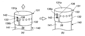
- the second combustion chamber cup 130 is a combination of a cup member 131 and a cylindrical member 140.
- the inside of the second combustion chamber cup 130 becomes the second combustion chamber 46 and is filled with a known second gas generating agent 43.
- the cup member 131 is placed on the second end opening 140b side of the cylindrical member 140, and the bottom surface 131a of the cup member 131 is located on the housing top plate 12a side.
- the cylindrical member 140 is fixed by fitting the first end opening 140 a into the collar 26. By adjusting the inner diameter of the cup member 131 and the outer diameter of the cylindrical member 140, the cup member 131 and the cylindrical member 140 can be fitted into the cylindrical member 140 without any gap therebetween.
- FIGS. 2 and 3 As the cup member 131 and the cylindrical member 140, those shown in FIGS. 2 and 3 can be used.
- FIG. 1 the cup member 131 shown in FIG. 2 (a) is used.
- FIG. 1 there is a gap between the bottom surface 131 a of the cup member 131 and the top plate 12 a of the housing.
- the cup member 131 moves in the axis X direction during operation. Since the movement may be hindered, a sufficiently flexible cushion material that does not hinder the movement of the cup member 131 may be disposed so that the first gas generating agent 33 does not enter.
- the second combustion chamber cup 130 is arranged such that the central axis X 2 is offset radially outward from the central axis X of the housing 11.
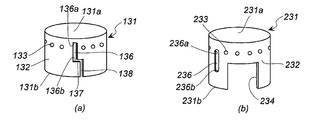
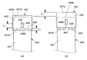
- the cup member 131 shown in FIG. 2A has a bottom surface 131a, a peripheral wall surface 132, and an opening 131b.
- a plurality of through holes 133 are formed at equal intervals in the circumferential direction on the bottom surface 131 a side of the peripheral wall surface 132.
- a drop-off prevention slit 136, a connection slit 137, and an introduction slit 138 are continuously formed in a portion of the peripheral wall surface 132 where the through hole 133 is not formed.
- the drop-off preventing slit 136 is formed in the axial direction from the first end 136a on the bottom surface 131a side to the second end 136b on the opening 131b side.
- connection slit 137 is formed in the circumferential direction from the second end portion 136 b of the drop-off prevention slit 136.
- the introduction slit 138 is formed from the connection slit 137 to the opening 131b. Note that the drop-off prevention slit 136, the connection slit 137, and the introduction slit 138 can be formed at two locations facing the radial direction of the peripheral wall surface 132.
- the cup member 231 shown in FIG. 2B has a bottom surface 231a, a peripheral wall surface 232, and an opening 231b.
- a plurality of through holes 233 are formed at equal intervals in the circumferential direction on the bottom surface 231a side of the peripheral wall surface 232.
- a drop prevention slit 236 is formed in a portion of the peripheral wall surface 232 where the through hole 233 is not formed.
- the drop-off prevention slit 236 is formed in the axial direction from the first end 236a on the bottom surface 231a side to the second end 236b on the opening 231b side.
- the drop-off prevention slits 236 can be formed at two locations facing the radial direction of the peripheral wall surface 232.
- the peripheral wall surface 232 has a cutout portion 234 in which a part without the dropout prevention slit 236 and the through hole 233 is cut off.
- the cut-out portion 234 is also formed on the peripheral wall surface 232 facing directly in the radial direction.
- the two cutout portions 234 are formed to make the opening 231b side of the cup member 231 easier to expand radially outward and to reduce the weight.
- the shape of the cut-out portion 234 may be any shape that can exhibit the above functions, and may be a square, a rectangle, a trapezoid, or a partial circle (such as a semicircle).
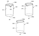
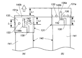
- the cylindrical member 140 shown in FIG. 3A has a first end opening 140a, a peripheral wall surface 141, and a second end opening 140b.
- the peripheral wall surface 141 is formed with two protrusions 142 protruding outward in the radial direction at a portion facing the radial direction.
- the protrusion 142 is obtained by bending the peripheral wall surface 141 of the second end opening 140b at two locations in the axial direction with an interval in the circumferential direction and bending it outward.
- the cylindrical member 240 shown in FIG. 3B has a first end opening 240a, a peripheral wall surface 241 and a second end opening 240b.
- a protrusion 242 protruding outward in the radial direction is formed on the peripheral wall surface 241.
- the protrusion 242 is obtained by cutting the circumferential wall surface 241 of the second end opening 240b in the axial direction, further cutting in the circumferential direction, and bending outward.
- a cylinder member 340 shown in FIG. 3C has a first end opening 340a, a peripheral wall surface 341, and a second end opening 340b.
- a protrusion (cylindrical protrusion) 342 protruding outward in the radial direction is formed on the peripheral wall surface 341.
- the protrusion 342 is obtained by fixing a protrusion of another member to the peripheral wall surface 341 by a method such as welding.
- the protrusion 142 is introduced from the introduction slit 138 and passes through the connection slit 137 and the first end 136a of the drop-off prevention slit 136. Fit into position.
- the width of the protrusion 142 and the width of the introduction slit 138 are set so that the width of the introduction slit 138 is slightly increased to facilitate passage.
- the thickness of the protrusion 142 and the width of the connection slit 137 are set so that the width of the connection slit 137 is slightly increased to facilitate passage.
- the width of the protrusion 142 and the width of the drop-off prevention slit 136 are made slightly larger than the width of the drop-off prevention slit 136 to facilitate passage.
- the protrusion 242 is introduced from the introduction slit 138 and passes through the connection slit 137 to the first end portion 136a of the drop prevention slit 136. Fit into position.
- the thickness of the protrusion 242 and the width of the introduction slit 138 are set so that the width of the introduction slit 138 is slightly increased to facilitate passage.
- the width of the protrusion 242 and the width of the connection slit 137 are set so that the width of the connection slit 137 is slightly increased to facilitate passage.
- the width of the drop-off prevention slit 136 is slightly increased to facilitate passage.
- the protrusion 342 is introduced from the introduction slit 138 and passes through the connection slit 137 and the first end 136a of the drop-off prevention slit 136. Fit into position.
- the outer diameter of the protrusion 342 and the width of the introduction slit 138 are set so that the width of the introduction slit 138 is slightly increased to facilitate passage.
- the outer diameter of the protrusion 342 and the width of the connection slit 137 are set so that the width of the connection slit 137 is slightly increased to facilitate passage.
- the outer diameter of the protrusion 342 and the width of the drop-off prevention slit 136 are made slightly larger than the width of the drop-off prevention slit 136 to facilitate passage.
- the opening 231b side of the cup member 231 is expanded outward in the radial direction, and the first end 236a side of the drop-off prevention slit 236 is placed. Is fitted into the protrusion 142.
- the width of the protrusion 142 and the width of the drop-off prevention slit 236 are set so that the width of the drop-off prevention slit 236 is slightly increased to facilitate fitting.
- the opening 231b side of the cup member 231 is expanded outward in the radial direction, and the first end 236a side of the drop-off prevention slit 236 is placed. Is fitted into the protrusion 242.
- the thickness of the protrusion 242 and the width of the drop-off prevention slit 236 are set so that the width of the drop-off prevention slit 236 is slightly increased to facilitate fitting.
- the opening 231b side of the cup member 231 is expanded radially outward while the first end 236a side of the drop-off prevention slit 236 is placed. Is fitted into the protrusion 342.
- the outer diameter of the protrusion 342 and the width of the drop-off prevention slit 236 are set so that the width of the drop-off prevention slit 236 is slightly increased to facilitate fitting.
- the through hole in the cup member it is preferable to form the through hole in a range that is less than half of the length from the bottom surface side to the opening (range from the bottom surface side) in order to open the through hole reliably.
- the first igniter 21 and the second igniter 25 are configured such that when only the first igniter 21 is activated according to the degree of impact at the time of collision, the first igniter 21 is activated first and the second igniter is activated.
- the igniter 25 is operated with a delay, the first igniter 21 and the second igniter 25 may be operated at the same time.
- the first igniter 21 is activated first and the second igniter 25 is activated. A case where the operation is delayed will be described.
- the operation signal from the control unit is received, the first igniter 21 is activated and ignited, and the transfer charge 35 in the ignition chamber 30 is ignited and burned.
- Combustion products (such as high-temperature gas and flame) enter the first combustion chamber 31 through the first communication hole 34 and ignite and burn the first gas generating agent 33 to generate combustion gas.
- the through hole (second communication hole) 133 formed in the cup member 131 of the second combustion chamber cup 130 is closed from the inside by the peripheral wall surface 141 of the cylindrical member 140, and the second combustion is performed by the combustion gas.
- the second gas generating agent 43 in the chamber 46 is not ignited and burned.
- the combustion gas generated from the first gas generating agent 33 in the first combustion chamber 31 is filtered and cooled through the filter 18, then breaks the seal tape 16 and is discharged from the gas discharge port 14.
- the second igniter 25 is activated and ignited after the first igniter 21, the second gas generating agent 43 in the second combustion chamber 46 is ignited and burned, and combustion gas is generated.
- the cup member 131 slides upward (axial X 2 direction in FIG. 1).
- the drop prevention slit 136 also moves upward.
- the upward sliding of the cup member 131 is stopped when the second end portion 136b hits the protrusion 142, it is generated from the first gas generating agent 33. Even when the housing 11 is deformed in the direction of the axis X in response to the pressure increase caused by the combustion gas, the cup member 131 does not come off the cylinder member 140.
- the cup member 131 moves by a length L1 (corresponding to a length obtained by subtracting the thickness of the protrusion 142 from the axial length of the drop-off prevention slit 136), but the length L1 is changed to the length L2. (L1> L2) (the length from the second end opening 140b of the cylindrical member to the lower end of the through-hole 133 in a state where the protrusion 142 is positioned on the first end 136a side before operation).
- L1> L2 the length from the second end opening 140b of the cylindrical member to the lower end of the through-hole 133 in a state where the protrusion 142 is positioned on the first end 136a side before operation.
- the opening is larger than the total opening area of the through hole 133, and the combustion performance of the second gas generating agent 43 is not stable.
- the cup member 131 is in the cylindrical member 140 during operation. Therefore, the second gas generating agent 43 is stably combusted.
- FIG. 6 is an axial sectional view showing another embodiment of the gas generator 100 of the present invention.
- the gas generator 100 has a housing 111 in which a diffuser shell 112 and a closure shell 113 are laser welded at a joint 114.
- the housing 111 is made of metal such as iron or stainless steel.
- a well-known cylindrical filter 120 is disposed in the housing 111.
- the diffuser shell 112 has a top plate 112a and a peripheral wall portion 112b
- the closure shell 113 has a bottom plate 113a and a peripheral wall portion 113b.
- the required number of gas discharge ports 117 are provided in the diffuser shell 112 and are blocked from the inside by an aluminum seal tape 118 for moisture prevention.
- a retainer 134 is fitted on the top plate 112a side of the diffuser shell.
- a central hole is formed at the center of the bottom plate 113a of the closure shell 113, and a metal collar 149 is fitted and fixed by welding.
- An igniter 148 is attached to the collar 149, and the collar 149 is fixed to the bottom plate 113a.
- a retainer 152 is fitted on the bottom plate 113a side of the closure shell. The retainer 152 can adjust the capacity of the second combustion chamber 150 according to the filling amount of the second gas generating agent 151.
- FIG. 1 shows an example of the maximum capacity, and the retainer 152 is moved in the direction of the top plate 112a as the amount of the second gas generating agent 151 decreases.
- a stainless steel combustion chamber cup 130 is arranged in the housing 111 so as to be concentric with the housing 111.
- the inside of the combustion chamber cup 130 is a first combustion chamber (inner combustion chamber) 145, and the inside of the filter 120 outside the combustion chamber cup 130 is a second combustion chamber (outer combustion chamber) 150.
- a required amount of the first gas generating agent 146 is accommodated in the first combustion chamber 145, and a required amount of the second gas generating agent 151 is accommodated in the second combustion chamber 150.
- Both the first gas generating agent 146 and the second gas generating agent 151 can be known ones (for example, those described in JP-A No. 2005-1998867).
- a combustion temperature lower than the combustion temperature of the first gas generating agent 146 is used.
- the combustion chamber cup 130 is a combination of a cup member 131 and a cylindrical member 140.
- the cup member 131 covers the second end opening 140b side of the cylindrical member 140, and the bottom surface 131a of the cup member 131 is located on the housing top plate 112a side.
- the cylindrical member 140 is fixed by the first end opening 140 a being fitted into the collar 149 and being sandwiched between the collar 149 and the retainer 152. Even when the retainer 152 is moved in the direction of the top plate 112a, the peripheral wall surface 141 of the cylindrical member 140 is still pressed radially inward, so that the cylindrical member 140 is fixed.
- the cup member 131 and the cylindrical member 140 can be fitted into the cylindrical member 140 without any gap therebetween.
- the cup member 131 and the cylindrical member 140 those shown in FIGS. 2 and 3 can be used.
- FIG. 6 the cup member 131 shown in FIG. 2 (a) is used.
- FIG. 6 there is a gap between the bottom surface 131a of the cup member 131 and the top plate 112a.
- the second gas generating agent 151 enters the gap, the movement of the cup member 131 in the direction of the axis X during operation is performed. Since there is a possibility of being hindered, a sufficiently flexible cushioning material that does not hinder movement of the cup member 131 can be arranged so that the second gas generating agent 151 does not enter.
- the cup member 131 and the cylindrical member 140 constituting the combustion chamber cup 130 are in the state shown in FIGS. 4 (a) and 5 (a). Since the through hole 133 of the cup member 131 is below the second opening 140b of the cylindrical member 140, the through hole 133 is closed from the inside by the peripheral wall surface 141. A protrusion 142 of the cylindrical member 140 is fitted on the first end 136 a side of the drop prevention slit 136 of the cup member 131. From the state before the operation shown in FIGS.
- the cup member 131 is moved upward by at least a length L2 from the lower end portion of the through hole 133 to the second end opening portion 140b (axis X in FIG. 1).
- the through hole 133 appears above the second end opening 140b and is opened.
- the igniter 148 When the automobile collides, a command from the impact sensor is received, the igniter 148 is activated, the first gas generating agent 146 in the combustion chamber cup 130 (first combustion chamber 145) is ignited and burned, and the combustion product is removed. generate.
- the pressure in the combustion chamber cup 130 (first combustion chamber 145) increases, the cup member 131 slides upward (in the direction of the axis X in FIG. 6). At this time, the drop prevention slit 136 also moves upward. However, since the upward sliding of the cup member 131 is stopped when the second end portion 136b hits the protrusion 142, the cup member 131 is detached from the cylindrical member 140. There is nothing.
- the cup member 131 moves by a length L1 (corresponding to a length obtained by subtracting the thickness of the protrusion 142 from the length of the drop-off prevention slit 136), but the length L1 is greater than the length L2 described above. (L1> L2), the through hole 133 appears above the second opening 140b and is opened. Therefore, the length L from the lower end of the through hole 133 of the cup member 131 to the opening 131b (that is, the length from the through hole 124 in FIGS. 3 to 5 of US-B No. 7374204 to the opening of the cap 120).
- the through-hole 133 is reliably opened, and the cup member 131 is dropped from the cylindrical member 140 by the combination of the drop-off prevention slit 136 and the protrusion 142. I don't have to.
- the opening is larger than the total opening area of the through-hole 133, and the combustion performance of the first gas generating agent 146 is not stable.
- the cup member 131 is the cylindrical member 140 during operation. The first gas generating agent 146 is stably burned without falling off.
- FIGS. 2 (a) and 3 (b), FIGS. 2 (a) and 3 (c), FIG. 2 (b) and FIG. (A), FIG. 2 (b) and FIG. 3 (b), and FIG. 2 (b) and FIG. 3 (c) may be combined.
- the gas generator of the present invention can use the combustion chamber cup of each of the following embodiments in place of the combustion chamber cup composed of the cylindrical member and the cup member in the gas generator of FIG. 1 or FIG.
- the cup member 431 shown in FIG. 7A has a bottom surface 431a, a peripheral wall surface 432, and an opening 431b.
- a drop prevention slit 436 is formed in the peripheral wall surface 432.
- the drop-off prevention slit 436 is formed in the axial direction from the first end 436a on the bottom surface 431a side to the second end 436b on the opening 431b side.
- the drop-off prevention slits 436 can also be formed at two locations facing the radial direction of the peripheral wall surface 432.
- the cylindrical member 440 shown in FIG. 7A is the same as the cylindrical member 340 shown in FIG. 3C except that the shape of the protrusion and the through hole 443 are provided.
- the cylindrical member 440 has a peripheral wall surface 441 and a second end opening 440b, and has a first end opening on the opposite side of the second end opening 440b.
- a plurality of through holes 443 are formed at equal intervals in the circumferential direction, and further, protrusions 442 protruding outward in the radial direction are formed.
- the plurality of through holes 443 are formed above the half of the height of the cylindrical member 440 (on the second end opening 440b side). If the formation position of the through hole 443 is on the lower side, the cup member 431 is deepened, so that it is difficult to reduce the weight.
- the protrusion 442 is formed around an intermediate position between the second end opening 440 b and the through hole 443.
- the tubular member 440 is covered with a cup member 431 and used in the gas generator of FIG. 1 or FIG. At this time, adjustment is performed so that L1> L3.
- the length L1 corresponds to a length obtained by subtracting the thickness of the protrusion 442 from the axial length of the drop-off prevention slit 436.
- the length L3 is a length from the upper end portion of the through hole 443 to the opening portion 431b when the cup member 431 is attached to the cylindrical member 440 with the projection 442 positioned on the first end portion 436a side before operation. That's it.
- the cup member 431 moves by the length L1, but by setting the length L1 to be larger than the length L3 (L1> L3), the through hole 443 appears below the opening 431b and opens. (FIG. 7B).
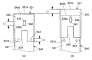
- the cup member 531 shown in FIG. 8A has a bottom surface 531a, a peripheral wall surface 532, and an opening 531b.
- a drop prevention slit 536 is formed in the peripheral wall surface 532.
- the drop-off prevention slit 536 is formed in the axial direction from the first end 536a on the bottom 531a side to the second end 536b on the opening 531b side.
- the drop-off prevention slits 536 can also be formed at two locations facing the radial direction of the peripheral wall surface 532.
- the peripheral wall surface 532 has a cutout portion 534 that is partially cut away without the dropout prevention slit 536.
- the cutout portion 534 is also formed on the peripheral wall surface 532 that faces the radial direction.
- the two cutout portions 534 are formed to make the opening 531b side of the cup member 531 easier to expand radially outward and to reduce the weight.
- the shape of the cut-out portion 534 may be any shape that can exhibit the above functions, and can be a square, a rectangle, a trapezoid, or a partial circle (such as a semicircle).
- the dropout prevention slit 536 and the cutout portion 534 are formed on the same axis, but may not be formed on the same axis.
- the cylindrical member 540 shown in FIG. 8A is the same as the cylindrical member 340 shown in FIG. 3C except that the shape of the protrusion and the through hole 543 are provided.
- the cylindrical member 540 has a peripheral wall surface 541 and a second end opening 540b, and has a first end opening on the opposite side of the second end opening 540b.
- a plurality of through holes 543 are formed in the circumferential wall surface 541 at equal intervals in the circumferential direction, but are not formed in the circumferential wall surface 541 that faces the cutout portion 534 when combined with the cup member 531.
- On the peripheral wall surface 541, a protrusion 542 protruding outward in the radial direction is formed.
- the plurality of through holes 543 are formed at a position about half the height of the cylindrical member 540.
- the protrusion 542 is formed closer to the second end opening 540 b than the intermediate position between the second end opening 540 b and the through hole 543.
- the tubular member 540 is used in the gas generator of FIG. 1 or 6 with the cup member 531 covered.
- the cut-out portion 534 of the cup member 531 is located in a portion where the through wall 541 of the cylindrical wall surface 541 does not have the through hole 543. Since the protrusion 542 of the cylindrical member 540 is fitted into the drop-off prevention slit 536 of the cup member 531, the cup member 531 is prevented from rotating in the circumferential direction, so that the cutout portion 534 overlaps with the through hole 543 in the thickness direction.
- the through hole 543 is closed before operation.
- the cup member 531 moves by the length L1, but by making the length L1 larger than the length L3 (L1> L3), the through hole 543 appears below the opening 531b and opens. (FIG. 8B).
- the cup member 631 shown in FIG. 9A has a bottom surface 631a, a peripheral wall surface 632, and an opening 631b.
- a drop prevention slit 636 is formed in the peripheral wall surface 632.
- the drop-off prevention slit 636 is formed in the axial direction from the first end 636a on the bottom 631a side to the second end 636b on the opening 631b side.
- the drop-off prevention slits 636 can also be formed at two locations facing the radial direction of the peripheral wall surface 632.
- the peripheral wall surface 632 has a cut-out portion 634 in which a part without the drop-off prevention slit 636 is cut out for weight reduction.
- the cutout part 634 has a part of the peripheral wall surface 632 cut out by half in the circumferential direction.
- the cylindrical member 640 shown in FIG. 9A is the same as the cylindrical member 340 shown in FIG. 3C except that it has a through hole 643.
- the cylindrical member 640 has a peripheral wall surface 641 and a second end opening 640b, and has a first opening on the opposite side of the second end opening 640b.
- a plurality of through holes 643 are formed in the circumferential wall surface 641 at equal intervals in the circumferential direction, but are not formed in the circumferential wall surface 641 that faces the cutout portion 634 when combined with the cup member 631.
- the peripheral wall surface 641 is formed with a protrusion 642 protruding outward in the radial direction.
- the plurality of through holes 643 are formed at positions about half the height of the cylindrical member 640.
- the protrusion 642 is formed closer to the second end opening 640 b than the intermediate position between the second end opening 640 b and the through hole 643.
- the tubular member 640 is used in the gas generator of FIG. 1 with the cup member 631 covered.
- the combustion gas is ejected from the through hole 643 of the combustion chamber cup in a specific direction. It can also be made to do.
- the ejection direction can be specified so that the through-hole 643 is positioned in a direction in which the distance from the inner peripheral surface of the filter 18 increases.
- the cutout portion 634 of the cup member 631 is located in a portion where the through wall 643 of the peripheral wall surface 641 of the cylindrical member 640 is not present. Since the protrusion 642 of the cylindrical member 640 is fitted into the drop-off prevention slit 636 of the cup member 631 and the cup member 631 is prevented from rotating in the circumferential direction, the cutout portion 634 overlaps the through hole 643 in the thickness direction.
- the through hole 643 is closed before operation.
- the cup member 631 moves by the length L1, but by setting the length L1 to be larger than the length L3 (L1> L3), the through hole 643 appears below the opening 631b and opens. (FIG. 9B).
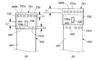
- a cup member 731 shown in FIG. 10A has a bottom surface 731a, a peripheral wall surface 732, and an opening 731b.
- a plurality of through holes 733 are formed at equal intervals in the circumferential direction on the bottom surface 731 a side of the peripheral wall surface 732.
- a drop prevention slit 736 is formed in a portion of the peripheral wall surface 732 where the through hole 733 is not formed.
- the drop-off prevention slit 736 is formed in the axial direction from the first end 736a on the bottom 731a side to the second end 736b on the opening 731b side.
- the drop-off prevention slits 736 can also be formed at two locations facing the radial direction of the peripheral wall surface 732.
- the cylindrical member 440 is the same as the cylindrical member 440 shown in FIG.
- the cylindrical member 440 is covered with a cup member 731 and used in the gas generator of FIG. 1 or FIG. At this time, adjustments are made so that L1> L3 and L1> L4.
- the length L1 corresponds to a length obtained by subtracting the thickness of the protrusion 442 from the axial length of the drop prevention slit 736.
- the length L3 is an opening of the cup member from the upper end of the through hole 443 of the tubular member when the cup member 731 is attached to the tubular member 440 in a state where the projection 442 is positioned on the first end side before operation.
- the length is up to 731b.
- the length L4 extends from the lower end of the through hole 733 of the cup member when the cup member 731 is attached to the cylindrical member 440 with the protrusion 442 positioned on the first end side before the operation. It is the length to the end opening 440b.
- the cup member 731 moves by a length L1.
- the through hole 443 of the cylindrical member appears below the opening 731b of the cup member and is opened, and the length L1 is greater than the above-described length L4.
- the through hole 733 of the cup member appears above the second end opening 440b of the cylindrical member and is opened (FIG. 10B).
- a cup member 831 shown in FIG. 11A has a bottom surface 831a, a peripheral wall surface 832, and an opening 831b.
- a plurality of through holes 833 are formed at equal intervals in the circumferential direction on the bottom surface 831 a side of the peripheral wall surface 832.
- a drop prevention slit 836 is formed in a portion of the peripheral wall surface 832 where the through hole 833 is not formed. The dropout prevention slit 836 is formed in the axial direction from the first end 836a on the bottom 831a side to the second end 836b on the opening 831b side.
- the drop-off prevention slits 836 can also be formed at two locations facing the radial direction of the peripheral wall surface 832.
- the peripheral wall surface 832 has a cutout portion 834 in which a part without the dropout prevention slit 836 and the through hole 833 is cut off.
- the cutout portion 834 is also formed on the peripheral wall surface 832 facing the radial direction.
- the two cutout portions 834 are formed to make the opening 831b side of the cup member 831 easier to expand radially outward and to reduce the weight.
- the shape of the cut-out portion 834 may be any shape as long as it can exhibit the above functions, and may be a square, a rectangle, a trapezoid, a partial circle (such as a semicircle), or the like.
- the drop-off prevention slit 836 and the cutout portion 834 are formed on the same axis, but may not be formed on the same axis.
- the cylindrical member 540 is the same as the cylindrical member
- the tubular member 540 is used in the gas generator of FIG. 1 or 6 with the cup member 831 covered.
- the cut-out portion 834 of the cup member 831 is located at a portion where the through wall 541 of the cylindrical member 540 is not provided with the through hole 543. Since the protrusion 542 of the cylindrical member 540 is fitted in the drop prevention slit 836 of the cup member 831 and the cup member 831 is prevented from rotating in the circumferential direction, the cutout portion 834 overlaps the through hole 543 in the thickness direction.
- the through hole 543 is closed before operation.
- the length L1 corresponds to a length obtained by subtracting the thickness of the protrusion 542 from the axial length of the drop slit 836.
- the length L3 is an opening of the cup member from the upper end of the through hole 543 of the tubular member when the cup member 831 is attached to the tubular member 540 in a state where the projection 542 is positioned on the first end side before operation.
- the length is up to 831b.
- the length L4 extends from the lower end of the through hole 833 of the cup member when the cup member 831 is attached to the cylindrical member 440 with the protrusion 542 positioned on the first end side before the operation.
- the cup member 831 moves by a length L1.
- the through hole 543 of the tubular member appears below the opening 831b of the cup member and is opened, and the length L1 is made larger than the above-described length L4.
- the through hole 833 of the cup member appears above the second opening 540b of the cylindrical member and is opened (FIG. 11B).
- the cup member 931 shown in FIG. 12A has a bottom surface 931a, a peripheral wall surface 932, and an opening 931b.
- a plurality of through holes 933 are formed at equal intervals in the circumferential direction on the bottom surface 931 a side of the peripheral wall surface 932.
- a drop-off prevention slit 936 is formed in a portion of the peripheral wall surface 932 where the through hole 933 is not formed.
- the drop-off prevention slit 936 is formed in the axial direction from the first end 936a on the bottom surface 931a side to the second end 936b on the opening 931b side.
- the drop-off prevention slits 936 can also be formed at two locations facing the radial direction of the peripheral wall surface 932.
- the peripheral wall surface 932 includes a cut-out portion 934 from which a part without the drop-off prevention slit 936 and the through-hole 933 is cut for weight reduction. A part of the peripheral wall surface 932 is cut out by half in the circumferential direction.
- the cylindrical member 640 shown in FIG. 12A is the same as the cylindrical member 640 shown in FIG.
- the cutout portion 934 of the cup member 931 is located in a portion where the through wall 643 of the peripheral wall surface 641 of the cylindrical member 640 is not present. Since the protrusion 642 of the cylindrical member 640 is fitted in the drop-off prevention slit 936 of the cup member 931 and the cup member 931 is prevented from rotating in the circumferential direction, the cutout portion 934 overlaps the through-hole 643 in the thickness direction. The through hole 643 is closed before operation.
- the length L1, L3, and L4 are adjusted so that L1> L3 and L1> L4.
- the length L 1 corresponds to a length obtained by subtracting the thickness of the protrusion 642 from the length of the drop-off slit 936.
- the length L3 is an opening of the cup member from the upper end portion of the through hole 643 of the tubular member when the cup member 931 is attached to the tubular member 640 with the protrusion 642 positioned on the first end side before operation.
- the length is up to 931b.
- the length L4 extends from the lower end of the through hole 933 of the cup member when the cup member 931 is attached to the cylindrical member 640 in a state where the protrusion 642 is positioned on the first end side before the operation.
- the cup member 931 moves by a length L1.
- the through hole 643 of the tubular member appears below the opening 931b of the cup member and is opened, and the length L1 is larger than the length L4.
- the through hole 933 of the cup member appears above the second opening 640b of the cylindrical member and is opened (FIG. 12B).
Landscapes
- Physics & Mathematics (AREA)
- Fluid Mechanics (AREA)
- Engineering & Computer Science (AREA)
- Mechanical Engineering (AREA)
- Chemical & Material Sciences (AREA)
- Organic Chemistry (AREA)
- Chemical Kinetics & Catalysis (AREA)
- Air Bags (AREA)
- Feeding, Discharge, Calcimining, Fusing, And Gas-Generation Devices (AREA)
Priority Applications (4)
| Application Number | Priority Date | Filing Date | Title |
|---|---|---|---|
| DE112015003553.2T DE112015003553B4 (de) | 2014-08-01 | 2015-07-21 | Gaserzeuger mit axial bewegbarem Schalenglied |
| US15/323,680 US9994190B2 (en) | 2014-08-01 | 2015-07-21 | Gas generator |
| KR1020177001054A KR20170040190A (ko) | 2014-08-01 | 2015-07-21 | 가스 발생기 |
| CN201580041178.3A CN106660510B (zh) | 2014-08-01 | 2015-07-21 | 气体发生器 |
Applications Claiming Priority (2)
| Application Number | Priority Date | Filing Date | Title |
|---|---|---|---|
| JP2014157323A JP6282555B2 (ja) | 2014-08-01 | 2014-08-01 | ガス発生器 |
| JP2014-157323 | 2014-08-01 |
Publications (1)
| Publication Number | Publication Date |
|---|---|
| WO2016017465A1 true WO2016017465A1 (ja) | 2016-02-04 |
Family
ID=55217368
Family Applications (1)
| Application Number | Title | Priority Date | Filing Date |
|---|---|---|---|
| PCT/JP2015/070635 Ceased WO2016017465A1 (ja) | 2014-08-01 | 2015-07-21 | ガス発生器 |
Country Status (6)
| Country | Link |
|---|---|
| US (1) | US9994190B2 (enExample) |
| JP (1) | JP6282555B2 (enExample) |
| KR (1) | KR20170040190A (enExample) |
| CN (1) | CN106660510B (enExample) |
| DE (1) | DE112015003553B4 (enExample) |
| WO (1) | WO2016017465A1 (enExample) |
Cited By (2)
| Publication number | Priority date | Publication date | Assignee | Title |
|---|---|---|---|---|
| US11485313B2 (en) * | 2020-06-23 | 2022-11-01 | Autoliv Asp, Inc. | Inflator for a passive vehicle safety device |
| US20240075900A1 (en) * | 2021-05-11 | 2024-03-07 | Daicel Corporation | Igniter Assembly and Gas Generation Device |
Families Citing this family (16)
| Publication number | Priority date | Publication date | Assignee | Title |
|---|---|---|---|---|
| JP6353326B2 (ja) * | 2014-09-16 | 2018-07-04 | 株式会社ダイセル | ガス発生器 |
| DE102015215025B4 (de) * | 2015-08-06 | 2020-09-24 | Joyson Safety Systems Germany Gmbh | Gasgeneratorbaugruppe mit Leitelement |
| WO2017130735A1 (ja) * | 2016-01-26 | 2017-08-03 | 株式会社ダイセル | ガス発生器 |
| JP6930981B2 (ja) * | 2016-08-29 | 2021-09-01 | 株式会社ダイセル | ガス発生器 |
| JP6797072B2 (ja) * | 2017-05-01 | 2020-12-09 | 株式会社ダイセル | ガス発生器 |
| JP6888228B2 (ja) * | 2017-07-20 | 2021-06-16 | 株式会社ダイセル | ガス発生器 |
| JP7199296B2 (ja) * | 2018-10-05 | 2023-01-05 | 日本化薬株式会社 | ガス発生器 |
| JP7175165B2 (ja) * | 2018-11-16 | 2022-11-18 | 日本化薬株式会社 | ガス発生器 |
| JP7175173B2 (ja) * | 2018-12-12 | 2022-11-18 | 日本化薬株式会社 | ガス発生器 |
| JP7306902B2 (ja) | 2019-07-12 | 2023-07-11 | 株式会社ダイセル | ガス発生器 |
| JP7343354B2 (ja) * | 2019-10-16 | 2023-09-12 | 株式会社ダイセル | ガス発生器、及びガス発生器の組立方法 |
| DE102019131394A1 (de) * | 2019-11-21 | 2021-05-27 | Zf Airbag Germany Gmbh | Gasgenerator für ein fahrzeugsicherheitssystem, verfahren zum betreiben eines gasgenerators |
| JP7534871B2 (ja) * | 2020-06-02 | 2024-08-15 | 株式会社ダイセル | ガス発生器及びその製造方法 |
| JP7587443B2 (ja) * | 2021-03-02 | 2024-11-20 | 日本化薬株式会社 | 点火器およびガス発生器 |
| US11479205B2 (en) * | 2021-03-17 | 2022-10-25 | Autoliv Asp, Inc. | Dual stage inflator |
| JP7702305B2 (ja) * | 2021-08-23 | 2025-07-03 | 株式会社ダイセル | エアバッグ装置及びガス発生装置 |
Citations (5)
| Publication number | Priority date | Publication date | Assignee | Title |
|---|---|---|---|---|
| JPH08156737A (ja) * | 1994-12-06 | 1996-06-18 | Nippon Kayaku Co Ltd | エアバッグ用ガス発生器 |
| US5984351A (en) * | 1997-04-11 | 1999-11-16 | Autoliv Asp, Inc. | Dual stage actuation system |
| US6315322B1 (en) * | 1999-03-05 | 2001-11-13 | Trw Inc. | Air bag inflator |
| JP2009517263A (ja) * | 2005-11-28 | 2009-04-30 | オートリブ エーエスピー,インコーポレイティド | インフレータ第二燃焼制御装置 |
| JP2009137478A (ja) * | 2007-12-07 | 2009-06-25 | Daicel Chem Ind Ltd | 車両の人員拘束装置用ガス発生器 |
Family Cites Families (6)
| Publication number | Priority date | Publication date | Assignee | Title |
|---|---|---|---|---|
| US7665764B2 (en) | 2004-01-15 | 2010-02-23 | Daicel Chemical Industries, Ltd. | Gas generator for air bag |
| JP4494023B2 (ja) | 2004-01-15 | 2010-06-30 | ダイセル化学工業株式会社 | エアバッグ用ガス発生器 |
| JP4970813B2 (ja) * | 2006-03-22 | 2012-07-11 | 株式会社ダイセル | 車両の人員拘束装置用ガス発生器 |
| JP5255967B2 (ja) * | 2008-09-19 | 2013-08-07 | 株式会社ダイセル | ガス発生器 |
| JP5462049B2 (ja) * | 2010-03-30 | 2014-04-02 | 株式会社ダイセル | ガス発生器 |
| JP5945152B2 (ja) * | 2012-04-25 | 2016-07-05 | 株式会社ダイセル | ガス発生器 |
-
2014
- 2014-08-01 JP JP2014157323A patent/JP6282555B2/ja active Active
-
2015
- 2015-07-21 KR KR1020177001054A patent/KR20170040190A/ko not_active Withdrawn
- 2015-07-21 CN CN201580041178.3A patent/CN106660510B/zh active Active
- 2015-07-21 WO PCT/JP2015/070635 patent/WO2016017465A1/ja not_active Ceased
- 2015-07-21 DE DE112015003553.2T patent/DE112015003553B4/de active Active
- 2015-07-21 US US15/323,680 patent/US9994190B2/en active Active
Patent Citations (5)
| Publication number | Priority date | Publication date | Assignee | Title |
|---|---|---|---|---|
| JPH08156737A (ja) * | 1994-12-06 | 1996-06-18 | Nippon Kayaku Co Ltd | エアバッグ用ガス発生器 |
| US5984351A (en) * | 1997-04-11 | 1999-11-16 | Autoliv Asp, Inc. | Dual stage actuation system |
| US6315322B1 (en) * | 1999-03-05 | 2001-11-13 | Trw Inc. | Air bag inflator |
| JP2009517263A (ja) * | 2005-11-28 | 2009-04-30 | オートリブ エーエスピー,インコーポレイティド | インフレータ第二燃焼制御装置 |
| JP2009137478A (ja) * | 2007-12-07 | 2009-06-25 | Daicel Chem Ind Ltd | 車両の人員拘束装置用ガス発生器 |
Cited By (3)
| Publication number | Priority date | Publication date | Assignee | Title |
|---|---|---|---|---|
| US11485313B2 (en) * | 2020-06-23 | 2022-11-01 | Autoliv Asp, Inc. | Inflator for a passive vehicle safety device |
| US20240075900A1 (en) * | 2021-05-11 | 2024-03-07 | Daicel Corporation | Igniter Assembly and Gas Generation Device |
| US12275367B2 (en) * | 2021-05-11 | 2025-04-15 | Daicel Corporation | Igniter assembly and gas generation device |
Also Published As
| Publication number | Publication date |
|---|---|
| JP2016034768A (ja) | 2016-03-17 |
| DE112015003553T5 (de) | 2017-04-13 |
| US20170166160A1 (en) | 2017-06-15 |
| CN106660510B (zh) | 2019-03-15 |
| US9994190B2 (en) | 2018-06-12 |
| DE112015003553B4 (de) | 2023-12-21 |
| CN106660510A (zh) | 2017-05-10 |
| KR20170040190A (ko) | 2017-04-12 |
| JP6282555B2 (ja) | 2018-02-21 |
Similar Documents
| Publication | Publication Date | Title |
|---|---|---|
| JP6282555B2 (ja) | ガス発生器 | |
| JP5101923B2 (ja) | 車両の人員拘束用ガス発生器 | |
| JP6009997B2 (ja) | 人員拘束装置用ガス発生器 | |
| EP2552753B1 (en) | Gas generator | |
| EP2841312B1 (en) | Gas generator | |
| JP2016034768A5 (enExample) | ||
| CN109863065B (zh) | 气体发生器 | |
| US10974687B2 (en) | Gas generator | |
| JP6930981B2 (ja) | ガス発生器 | |
| JPWO2017130735A1 (ja) | ガス発生器 | |
| JP2017190003A (ja) | ガス発生器 | |
| JP5021447B2 (ja) | ガス発生器 |
Legal Events
| Date | Code | Title | Description |
|---|---|---|---|
| 121 | Ep: the epo has been informed by wipo that ep was designated in this application |
Ref document number: 15827577 Country of ref document: EP Kind code of ref document: A1 |
|
| WWE | Wipo information: entry into national phase |
Ref document number: 15323680 Country of ref document: US |
|
| ENP | Entry into the national phase |
Ref document number: 20177001054 Country of ref document: KR Kind code of ref document: A |
|
| WWE | Wipo information: entry into national phase |
Ref document number: 112015003553 Country of ref document: DE |
|
| 122 | Ep: pct application non-entry in european phase |
Ref document number: 15827577 Country of ref document: EP Kind code of ref document: A1 |