WO2016017414A1 - 直描型露光装置 - Google Patents
直描型露光装置 Download PDFInfo
- Publication number
- WO2016017414A1 WO2016017414A1 PCT/JP2015/070117 JP2015070117W WO2016017414A1 WO 2016017414 A1 WO2016017414 A1 WO 2016017414A1 JP 2015070117 W JP2015070117 W JP 2015070117W WO 2016017414 A1 WO2016017414 A1 WO 2016017414A1
- Authority
- WO
- WIPO (PCT)
- Prior art keywords
- exposure apparatus
- base material
- support member
- drawing type
- direct drawing
- Prior art date
- Legal status (The legal status is an assumption and is not a legal conclusion. Google has not performed a legal analysis and makes no representation as to the accuracy of the status listed.)
- Ceased
Links
Images





Classifications
-
- B—PERFORMING OPERATIONS; TRANSPORTING
- B41—PRINTING; LINING MACHINES; TYPEWRITERS; STAMPS
- B41C—PROCESSES FOR THE MANUFACTURE OR REPRODUCTION OF PRINTING SURFACES
- B41C1/00—Forme preparation
-
- G—PHYSICS
- G03—PHOTOGRAPHY; CINEMATOGRAPHY; ANALOGOUS TECHNIQUES USING WAVES OTHER THAN OPTICAL WAVES; ELECTROGRAPHY; HOLOGRAPHY
- G03F—PHOTOMECHANICAL PRODUCTION OF TEXTURED OR PATTERNED SURFACES, e.g. FOR PRINTING, FOR PROCESSING OF SEMICONDUCTOR DEVICES; MATERIALS THEREFOR; ORIGINALS THEREFOR; APPARATUS SPECIALLY ADAPTED THEREFOR
- G03F7/00—Photomechanical, e.g. photolithographic, production of textured or patterned surfaces, e.g. printing surfaces; Materials therefor, e.g. comprising photoresists; Apparatus specially adapted therefor
- G03F7/20—Exposure; Apparatus therefor
-
- H—ELECTRICITY
- H05—ELECTRIC TECHNIQUES NOT OTHERWISE PROVIDED FOR
- H05K—PRINTED CIRCUITS; CASINGS OR CONSTRUCTIONAL DETAILS OF ELECTRIC APPARATUS; MANUFACTURE OF ASSEMBLAGES OF ELECTRICAL COMPONENTS
- H05K3/00—Apparatus or processes for manufacturing printed circuits
Definitions
- the present invention relates to a direct-drawing type exposure apparatus that pattern-exposes a photosensitive resin by directly irradiating a photosensitive resin with a light having a wavelength in the ultraviolet region without drawing a mask and drawing a predetermined pattern. is there.
- Screen printing is a technique for printing ink on a printing object through a screen printing plate in which a mesh cloth called a cocoon, which has been made to have a predetermined opening pattern, is stretched around a frame.
- a photosensitive resin is applied to the ridge, exposed to ultraviolet rays through a mask (original plate), exposed, and then unnecessary portions are washed away (developed) to form a predetermined opening pattern. It is done by getting.
- Patent Document 1 Japanese Patent Application Laid-Open No. 11-320968
- DMD digital micromirror device
- FIG. 9 is an explanatory diagram of the direct drawing type exposure apparatus 200 described in the above publication.
- FIG. 9A is a schematic block diagram of the direct drawing type exposure apparatus 200.
- FIG. 9B is a schematic diagram showing a mirror configuration of the DMD 205 used in the direct drawing type exposure apparatus 200.
- FIG. 9C is a partially enlarged view of FIG.
- the DMD 205 includes m microscopic square mirrors M in the horizontal direction (the left-right direction in FIG. 9B and the direction in which the micromirrors M form a row) in the vertical direction ( 9 rows are arranged in the vertical direction in FIG. 9B and in which the rows of micromirrors M are arranged.
- a gap g is provided between the minute mirrors M adjacent to each other in the lateral direction.
- the micromirrors M in each row (M11 to M16) are arranged with a predetermined distance from the micromirrors M in the adjacent upper and lower rows.
- the photosensitive resin PP that is an exposure object is in the form of a film, for example, in the form of a dry film of a single resin, or a liquid resin is applied on a substrate (not shown). After that, it is placed on the table 203 in a dried state.
- the table 203 is movable on the base 202 in the Y direction.
- each micromirror M is configured such that the end Mb is rotatable about a diagonal line connecting the pair of end Ma as a rotation axis.
- the DMD control device 206 individually controls the rotation of each micromirror M of the DMD 205.
- the light having a wavelength in the ultraviolet region output from the light source 201 is converted into parallel light 201 a by the collimator lens 204 and enters the DMD 205.
- the direction of the reflected light of the parallel light 201a is determined by how each incident micromirror M is rotated.
- the reflected light from some of the micromirrors M is condensed by the microlens 207 and becomes an exposure light beam 201b, which is irradiated onto the exposure surface of the photosensitive resin PP, thereby contributing to the exposure.
- the reflected light from another micromirror M is irradiated to a position away from the photosensitive resin PP and does not contribute to exposure.
- the photosensitive resin PP can be subjected to pattern exposure by controlling the individual rotation angle of the micro mirror M of the DMD 205.
- a liquid photosensitive resin PP is applied on the ridge S stretched on the frame body F, and then dried, the screen printing plate is patterned by the direct drawing type exposure apparatus 200. Think about exposure.
- the liquid photosensitive resin PP is applied on the ridge S with a uniform film thickness so that the upper surface PPu and the lower surface PPl in the drawing are parallel to each other. It is assumed that the thickness of the frame F is not uniform.
- the heel S stretched on the frame F is slightly inclined with respect to the upper surface of the table 203. If the inclination angle is ⁇ , the optical axis 201c of the exposure light beam 201b and the upper surface PPu are not orthogonal to each other, and the normal direction PPn of the upper surface PPu is inclined by the angle ⁇ with respect to the optical axis 201c of the exposure light beam 201b. .
- FIG. 10 (B) When exposed and developed in this state, as shown in FIG. 10 (B), it is inclined by an angle ⁇ with respect to the normal direction PPn of the upper surface PPu, and the opening position Au on the upper surface PPu side and the opening position Al on the lower surface PPl side. A misaligned opening pattern is formed.
- Screen printing is performed such that the upper surface PPu of the photosensitive resin in FIG.
- alignment with the printing object is performed from the lower surface PPl side. If the opening position is shifted between the upper surface PPu side and the lower surface PPl side, the ink is actually printed on the printing object even if alignment is performed at the opening position on the lower surface PPl side. Thus, printing misalignment occurs.
- the projection image of the exposure light beam 201b on the upper surface PPu is distorted according to the deviation from the orthogonality. For example, if the cross section perpendicular to the optical axis 201c of the exposure light beam 201b is circular, the exposure light beam 201b is distorted into an ellipse on the upper surface PPu. If the projection image of the exposure light beam 201b on the upper surface PPu has a distortion, the opening pattern is also distorted.
- an object of the present invention is to perform pattern exposure in a state where the optical axis of the exposure light beam is always orthogonal to the exposure surface of the photosensitive resin, even if the thickness of the substrate supporting the photosensitive resin is not uniform. It is to provide a direct drawing type exposure apparatus that can be used.
- the height position of the base material supporting the photosensitive resin at the time of exposure is such that the pattern exposure can be performed with the optical axis of the exposure light beam orthogonal to the exposure surface of the photosensitive resin. Improvements to the mechanism for determining the value are made.
- the direct-drawing type exposure apparatus performs pattern exposure by directly irradiating an exposure light beam in a predetermined pattern onto a film-like photosensitive resin held on a plate-like substrate with the following configuration.
- a direct-drawing exposure apparatus includes a light source that outputs an exposure light beam, a base, a plurality of displacement mechanisms including a drive unit and a drive shaft, a support member that can support the lower surface central region of the substrate, Is provided.
- the plurality of displacement mechanisms can support the lower surface peripheral region of the substrate and operate to displace the substrate in the optical axis direction of the exposure light beam.
- the optical axis of the exposure light beam and the upper surface of the support member are orthogonal to each other in a state where the base member is displaced by a plurality of displacement mechanisms and the upper surface of the support member and the lower surface central region of the support member are in contact with each other. As described above, it is disposed above the base.
- the optical axis of the exposure light beam and the upper surface of the base material in a state where the plurality of displacement mechanisms displace the base material and the upper surface of the support member and the lower surface central region of the base material are in contact with each other. And are orthogonal.
- pattern exposure can be performed in a state where the optical axis of the exposure light beam is always orthogonal to the upper surface (exposure surface) of the photosensitive resin provided on the upper surface of the substrate within an allowable error range. .
- the opening position of the opening pattern does not shift between the upper surface side and the lower surface (alignment surface) side of the photosensitive resin. Further, the opening pattern is not distorted.
- the drive shaft has an elastically deforming portion that is elastically deformed with respect to axial stress.
- the base material is supported by the drive shaft of the displacement mechanism in a state where the elastic deformation portion is deformed by its weight at the initial position.
- the support member receives at least a part of the weight of the base material when the upper surface of the support member comes into contact with the central region of the lower surface of the base material.
- the elastically deforming portion of the drive shaft is reversely deformed so as to return to the original shape as much as the load applied in the axial direction is reduced.
- the elastic deformation portion only slightly reversely deforms. Continue to support. That is, it is avoided that the base material is suddenly supported only by the support member.
- a mesh cloth called a heel stretched as described above is used for the frame, the frame is not supported by the drive shaft, and the lower surface central region of the heel is supported by the support member.
- the heel may be pulled by the weight of the frame and elastically deformed.
- the exposure pattern is deformed by releasing the elastic deformation, which is different from the desired opening pattern.
- a second preferred embodiment of the direct drawing type exposure apparatus further includes a load detection unit that is connected to the drive shaft and detects a load applied in the axial direction of the drive shaft, and a control device.
- the control device performs control so as to give an operation command to stop the operation to the drive unit based on information that informs that the load detected by the load detection unit has decreased to a predetermined value.
- the load applied to the drive shaft reaches a predetermined value as a result of the support member receiving at least a part of the weight of the substrate by the substrate contacting the support member.
- the load detection unit detects the decrease.
- the information is transmitted to the control device, and the control device gives an operation command to stop the operation to the drive unit based on the information.
- the displacement mechanism reliably displaces the base material until the load detection unit detects that the load applied to the drive shaft has decreased to a predetermined value. Therefore, the upper surface of the support member and the center area of the lower surface of the substrate can be reliably brought into contact with each other, and the optical axis of the exposure light beam and the upper surface of the support member can be reliably orthogonal to each other.
- the predetermined value is preferably a load value of about 80 to 99% of the load value detected by the load detection unit before the base material comes into contact with the support member.
- the control unit controls the drive unit to give an operation command to stop the operation.
- the drive unit does not need to displace the drive shaft too much. That is, as in the first preferred embodiment, it is possible to avoid the base material being supported only by the support member.
- the control device stops the operation of the drive unit so that the frame body is continuously supported by the drive shaft.
- the heel is hardly pulled as in the first preferred embodiment. That is, no elastic deformation that cannot be ignored occurs in the heel.
- the upper surface of the support member comes into contact with the central region of the lower surface of the ridge, and the optical axis of the exposure light beam and the ridge It is orthogonal to the top surface.
- the exposure surface of the photosensitive resin applied to the upper surface of the ridge is not inclined with respect to the optical axis of the exposure light beam.
- a third preferred embodiment of the direct-drawing type exposure apparatus is a distance detection unit that detects a distance to the upper surface of the base material corresponding to a location supported by the drive shaft in the lower peripheral edge region of the base material. And a control device.
- the control device gives an operation command for stopping the operation to the drive unit based on information from the distance detection unit that informs that the distance between the distance detection unit and the upper surface of the base material has increased to a predetermined value. To control.
- the distance detection unit detects that the distance between the distance detection unit and the upper surface of the substrate has increased to a predetermined value as a result of the plurality of displacement mechanisms displacing the substrate. .
- the information is transmitted to the control device, and the control device gives an operation command to stop the operation to the drive unit based on the information.
- the displacement mechanism reliably displaces the substrate until the distance detection unit detects that the distance between the distance detection unit and the upper surface of the substrate has increased to a predetermined value. Therefore, both the contact between the upper surface of the support member and the lower surface central region of the base material and the contact between the lower surface peripheral region of the base material and the drive shaft are ensured, and the optical axis of the exposure light beam and the upper surface of the support member are reliably secured. Can be orthogonal.
- the predetermined value is preferably a distance between the distance detection unit and the upper surface of the base material when the upper surface of the support member and the lower surface central region of the base material are in contact with each other.
- the control unit controls the drive unit to give an operation command to stop the operation, thereby driving the drive unit. It is not necessary to displace the shaft too much. That is, as in the first and second preferred embodiments, it can be avoided that the base material is supported only by the support member.
- a base material in which a heel is stretched on a frame body is used, and a state in which the frame body is supported by a drive shaft of a displacement mechanism at an initial position is considered. Then, the drive shaft is displaced by the drive unit, and when the distance detected by the distance detection unit reaches the predetermined value, the control device stops the operation of the drive unit, and the frame body is continuously supported by the drive shaft. Like that. In this state, the heel is hardly pulled as in the first preferred embodiment. That is, no elastic deformation that cannot be ignored occurs in the heel.
- the upper surface of the support member is in contact with the central region of the lower surface of the collar, and the optical axis of the exposure light beam It is perpendicular to the top surface of the ridge.
- the exposure surface of the photosensitive resin applied to the upper surface of the ridge is not inclined with respect to the optical axis of the exposure light beam.
- a tilt detection mechanism and a tilt adjustment mechanism are further provided.
- the control device performs control so that an operation command for adjusting the tilt angle of the base is given to the tilt adjustment mechanism based on information from the tilt detection mechanism.
- control device adjusts the tilt angle of the base by operating the tilt adjustment mechanism based on information from the tilt detection mechanism.
- the inclination angle thereof can be adjusted by adjusting the inclination angle of the base.
- the angle between the optical axis of the exposure light beam and the upper surface of the substrate is orthogonal in the state where the upper surface of the support member and the lower surface central region of the substrate are in contact with each other.
- the optical axis of the exposure light beam and the upper surface of the substrate are orthogonal to each other in a state where the upper surface of the support member and the lower surface central region of the substrate are in contact with each other.
- pattern exposure can be performed in a state where the optical axis of the exposure light beam is always orthogonal to the upper surface (exposure surface) of the photosensitive resin provided on the upper surface of the substrate within an allowable error range. .
- the opening position of the opening pattern does not shift between the upper surface side and the lower surface (alignment surface) side of the photosensitive resin. Further, the opening pattern is not distorted.
- FIG. 3 is a cross-sectional view of the direct drawing type exposure apparatus 100 according to the present invention (a cross-sectional view taken along the line Y1-Y1 in FIG. 2). It is a top view of the principal part of the direct drawing type exposure apparatus 100 concerning this invention.
- FIG. 2 is a cross-sectional view corresponding to FIG. 1 for schematically explaining the positioning of the height position of the base material B by the support member 7 in the direct drawing type exposure apparatus 100 according to the present invention.
- FIG. 6C is a cross-sectional view showing a state where the portion Sa of the heel S near the drive shaft 6a also abuts the upper surface of the support member 7, and as a result, the upper surface of the support member 7 and the lower surface central region of the heel S are in close contact. It is sectional drawing of the state contacted. It is sectional drawing equivalent to FIG. 1 of 1st modification 100A in the direct drawing type exposure apparatus which concerns on this invention. It is sectional drawing equivalent to FIG. 1 of the 2nd modification 100B in the direct drawing type exposure apparatus which concerns on this invention. It is sectional drawing equivalent to FIG. 1 of the 3rd modification 100C in the direct drawing type exposure apparatus which concerns on this invention.
- FIG. 9 is an explanatory diagram for explaining a problem to be solved by the present invention, and FIG. 9A shows a photosensitive resin PP on a ridge S stretched on a frame F having a non-uniform thickness.
- Sectional drawing which shows typically the principal part of the direct drawing type exposure apparatus 200 in the case of carrying out pattern exposure using the direct drawing type exposure apparatus 200 of the background art, (B) is the elements on larger scale of (A). .
- FIG. 1 is a sectional view of a direct drawing type exposure apparatus 100 according to this embodiment.
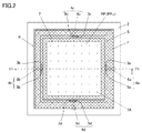
- FIG. 2 is a top view of the main part of the direct drawing type exposure apparatus 100 according to this embodiment.
- FIG. 1 is a cross-sectional view taken along the line Y1-Y1 in FIG.
- a direct drawing type exposure apparatus 100 exposes a film-like photosensitive resin PP held on the upper surface of a plate-like substrate B with the following configuration. Pattern exposure is performed by directly irradiating the light beam 1b in a predetermined pattern.
- the base material B a material in which a mesh cloth called heel S is stretched on the frame F as described above is used.
- a desired material such as a plate-shaped member made of any material can be used.
- the photosensitive resin PP is also in the form of a film as described above, for example, in the form of a dry film of a single resin, or in a state in which a liquid resin is applied on the ridge S and then dried. Things can be used.
- the non-uniformity of the thickness of the photosensitive resin PP is negligible, and the upper surface PPu (exposure surface) is assumed to be substantially parallel to the upper surface of the base material B ( ⁇ S).
- the direct drawing type exposure apparatus 100 includes a light source 1, a base 2, displacement mechanisms 4 a to 4 d, and a support member 7.
- the light source 1 outputs an exposure light beam 1b.
- the exposure light beam 1b is a light beam having a wavelength that causes a chemical change in the photosensitive resin PP.
- a light emitter of the light source 1 for that purpose for example, an ultraviolet laser, an ultra-high pressure mercury lamp, or an LED that emits light having a wavelength in the ultraviolet region can be used.
- the light source 1 may further include a lens system such as a collimator lens or a condenser lens.
- the light source 1 is movable in the horizontal direction and the vertical direction by the horizontal movement mechanism 1h and the vertical movement mechanism 1v. That is, in FIG. 1, pattern exposure is performed by moving the light source 1 horizontally by the horizontal movement mechanism 1 h without moving the base 2. Further, the focus position is adjusted by moving the light source 1 up and down by the vertical movement mechanism 1v.
- pattern exposure In order to perform pattern exposure, the irradiation position of the exposure light beam is changed by using the DMD described in JP-A-11-320968 and a reflecting mirror such as a galvano mirror without moving the light source 1. You may do it. Further, pattern exposure may be performed by moving the base 2 in at least one of the horizontal direction and the vertical direction by at least one of a horizontal movement mechanism and a vertical movement mechanism provided separately.
- the base 2 is not particularly limited in shape, and may be a flat plate or a recess formed by a bottom and a side wall.
- drive units 5a to 5d for driving displacement mechanisms 4a to 4d described later are respectively installed in recesses 3a to 3d provided on the upper surface of the base 2.
- the drive part 5a is installed in the recessed part 3a.
- the drive units 5b to 5d are also installed in the corresponding recesses 3b to 3d, respectively.
- the driving units 5a to 5d may be installed on the upper surface of the flat base 2 where the concave portions 3a to 3d are not provided.
- the displacement mechanisms 4a to 4d include a drive unit and a drive shaft that is displaced by the drive unit.
- the displacement mechanism 4a includes a drive unit 5a and a drive shaft 6a that is displaced by the drive unit 5a.
- the displacement mechanisms 4b to 4d have the same configuration as the displacement mechanism 4a, and include a drive unit 5b and a drive shaft 6b, a drive unit 5c and a drive shaft 6c, a drive shaft 5d and a drive shaft 6d, respectively.
- the drive units 5a to 5d are installed in the corresponding recesses 3a to 3d provided on the upper surface of the base 2, respectively.
- a cylinder stroke adjustment mechanism by pneumatic pressure or hydraulic pressure for example, a linear motion mechanism by a ball screw connected to a servo motor, a stepping motor with a lead screw, or the like can be preferably used.
- the positional relationship between the drive unit and the drive shaft is not limited to that shown in FIG. 1.
- a linear motor in which the drive shaft is installed on the upper surface of the base 2 and the drive unit moves on the drive shaft is used. It may be anything.
- the displacement mechanisms 4a to 4d can support the peripheral area of the lower surface of the base material B by the drive shaft provided in each. Furthermore, the displacement mechanisms 4a to 4d displace the base material B in the optical axis direction of the exposure light beam 1b by driving the drive shafts by the drive units to which the drive shafts are connected.
- the displacement mechanisms 4a to 4d are configured to be able to operate independently.
- the drive units 5a to 5d are set so as to stop the drive of the connected drive shaft at a predetermined position and maintain the state (hold state).
- the optical axis of the exposure light beam 1 b and the upper surface of the support member 7 are orthogonal within an allowable error range in a state where the upper surface of the support member 7 and the lower surface central region of the base material B are in contact with each other.
- the stem 8 is disposed at a predetermined height above the base 2.
- An air passage 8 ⁇ / b> A is provided inside the stem 8.
- the support member 7 has an air passage 7A opened in the upper surface thereof.
- the air passage 7A communicates with a decompression mechanism (not shown) through an air chamber 7R and an air passage 8A formed by the flange portion 8G of the stem 8 and a recess provided on the lower surface of the support member 7.
- a decompression mechanism not shown
- the upper surface of the support member 7 is capable of adsorbing the lower surface central region of the base material B under reduced pressure.
- the direct drawing type exposure apparatus 100 Since the direct drawing type exposure apparatus 100 according to this embodiment has the above-described configuration, the lower surface central region of the base material B is supported in a state where the upper surface of the support member 7 and the lower surface central region of the base material B are in close contact with each other. Adsorbed and fixed by the member 7.
- the upper surface of the support member 7 and the upper surface PPu (exposure surface) of the photosensitive resin PP held on the upper surface of the base material B are parallel to each other.
- the base material B is a screen printing plate including the frame F and the heel S stretched thereon, and the thickness of the frame F is not uniform.
- the base material B is displaced in the optical axis direction of the exposure light beam 1b by the displacement mechanisms 4a and 4b.
- the base material B is displaced in the optical axis direction of the exposure light beam 1b to position the base material B at the time of exposure.
- the thickness (Fa) of the portion of the frame F that is displaced by the displacement mechanism 4a is larger than the thickness (Fb) of the portion that is displaced by the displacement mechanism 4b (see also FIG. 9A).
- the support member 7 allows the optical axis of the exposure light beam 1b and the upper surface of the support member 7 to be allowed when the upper surface of the support member 7 and the lower surface central region of the base material B are in contact with each other.
- the stem 8 is disposed at a predetermined height above the base 2 so as to be orthogonal within a possible error range.
- FIG. 3 (A) shows that the drive shafts 6a and 6b of the displacement mechanisms 4a and 4b supporting the lower surface peripheral region of the base material B are in the initial positions (before the displacement mechanisms 4a and 4b are operated). It is sectional drawing showing the state in a position of (). In addition, in the initial position, the height position H from the upper surface of the base 2 of the edge part which contact
- the height position of the portion Sb close to the drive shaft 6b of the rod S stretched on the frame F is lower than the height position of the portion Sa close to the drive shaft 6a. That is, the portion Sb of the rod S near the drive shaft 6b is closer to the support member 7 than the portion Sa near the drive shaft 6a. Therefore, the normal direction PPn of the upper surface PPu of the photosensitive resin PP is inclined by the angle ⁇ with respect to the optical axis 1c of the exposure light beam 1b.
- FIG. 3B shows a state in which the portion Sb close to the drive shaft 6b of the heel S is in contact with the upper surface of the support member 7 when the displacement mechanisms 4a and 4b are operated and the frame body F is displaced. It is sectional drawing.
- the portion Sa of the kite S close to the drive shaft 6a is not yet in contact with the upper surface of the support member 7. Since the displacement mechanisms 4a and 4b are configured to be able to operate independently, the displacement mechanism 4a continues to move the frame F even when the displacement mechanism 4b is in the hold state.
- FIG. 3C is a cross-sectional view showing a state in which the portion Sa near the drive shaft 6a of the heel S is also in contact with the upper surface of the support member 7 as the displacement mechanism 4a continues to operate and the drive shaft 6a is further displaced. It is. As a result, the upper surface of the support member 7 and the lower surface central region of the flange S are in close contact with each other.
- the upper surface of the support member 7 and the upper surface PPu (exposure surface) of the photosensitive resin PP held on the upper surface of the ridge S are parallel to each other. Therefore, in the above state, the upper surface PPu (exposure surface) of the photosensitive resin PP is at a height position orthogonal to the optical axis of the exposure light beam 1b within an allowable error range.
- the frame F is continuously supported by the drive shafts 6a and 6b. In this state, the heel is hardly pulled because the heel only has a very small frame weight.
- the displacement mechanisms 4a and 4b operate independently in consideration of the elastic deformation of the heel S, and the frame F remains on the drive shaft 6a even after the height position of the base material B is positioned. And 6b continued to be supported.
- the drive shafts 6a and 6b are displaced until they are separated from the lower surface of the frame F, and the base material B May be supported only by the support member 7.
- the displacement mechanisms 4a and 4b can be configured to operate in conjunction with each other.
- the base material B is made of, for example, a highly rigid plate-like member, and is essentially hardly elastically deformed even if the weight of the frame body F is applied.
- the direct drawing type exposure apparatus 100 even if the thickness of the base material B is not uniform, the lower surface central region of the base material B and the upper surface of the support member 7 are used. In this state, the optical axis of the exposure light beam 1b and the upper surface of the base material B are surely orthogonal to each other. Therefore, pattern exposure can be performed in a state where the optical axis of the exposure light beam 1b is orthogonal to the upper surface PPu (exposure surface) of the photosensitive resin PP.
- the driving shafts 6a to 6d sufficiently support the weight of the base material B, the elastic deformation that cannot be ignored in the heel S does not occur. Therefore, the photosensitive resin PP held on the upper surface of the base plate B is also elastically deformed. No state. As a result, the exposure pattern and the opening pattern after development can be matched with high accuracy.
- the opening position of the opening pattern is not shifted between the upper surface PPu side and the lower surface PPl side of the photosensitive resin PP.
- the opening pattern is not distorted, a highly accurate opening pattern can be obtained. That is, when the photosensitive resin PP is used for a printing plate such as a screen printing plate, it is possible to print ink with high accuracy at a desired position where alignment has been performed. Further, the dimensional variation of the print pattern can be reduced.
- FIG. 4 is a cross-sectional view of a direct drawing type exposure apparatus 100A according to the first modification.
- the drive shaft 6a is configured to prevent the base material B from being suddenly supported only by the support member 7 after the upper surface of the support member 7 comes into contact with the lower surface central region of the base material B. To 6d. Therefore, since other parts are the same as those of the direct drawing type exposure apparatus 100 according to the present invention described above, description thereof will be omitted.
- the drive shafts 6a to 6d each include a rigid body portion and an elastic deformation portion.
- the displacement mechanism 6a includes a rigid body portion 6as and an elastic deformation portion 6ae connected to the end of the rigid body portion 6as.
- the drive shafts 6b to 6d have the same configuration as the drive shaft 6a, and include a rigid body portion 6bs and an elastic deformation portion 6be, a rigid body portion 6cs and an elastic deformation portion 6ce, a rigid body portion 6ds and an elastic deformation portion 6de, respectively.
- the elastic deformation portions 6ae to 6de for example, rubber and springs can be preferably used. Further, the positional relationship between the rigid body portion and the elastic deformation portion in the drive shafts 6a to 6d is not limited to that shown in FIG. 4, but for example, the drive shaft may have two rigid body portions connected by the elastic deformation portion. Good.
- the support member 7 receives at least a part of the weight of the substrate B when the upper surface of the support member 7 and the lower surface central region of the substrate B come into contact with each other.
- the upper surface of the support member 7 and the lower surface central region of the base material B come into contact with each other, and the load applied in the axial direction of the drive shafts 6a to 6d is reduced. Is reversely deformed to return to its original shape.
- the displacement mechanisms 4a to 4d further displace the base material B after the upper surface of the support member 7 and the lower surface central region of the base material B contact each other, the elastic deformation portions 6ae to 6de are slightly reversely deformed.
- the displacement mechanisms 4a to 4d continue to support the base material B. That is, it is possible to avoid that the base material B is suddenly supported only by the support member 7.
- the frame F continues to be reliably supported by the drive shafts 6a to 6d even after the height position of the base material B is positioned.
- the heel S is elastically deformed when pulled by the weight of the frame F, in the above configuration, the heel S is only slightly loaded with the weight of the frame F. ⁇ S is hardly pulled.
- the elastic deformation that cannot be ignored is not generated in the heel S.
- the exposure pattern and the opening pattern after development can be matched with high accuracy.
- FIG. 5 is a cross-sectional view of a direct drawing type exposure apparatus 100B according to a second modification.
- the direct drawing type exposure apparatus 100B is connected to each of the drive shafts 6a to 6d (drive shafts 6c and 6d are not shown) and applies a load applied in the axial direction of each of the drive shafts 6a to 6d. It further includes a load detection unit to detect, and a control device 11 to which the load detection unit and the drive unit are connected.
- the load detection unit 9a is attached to the end of the drive shaft 6a that is in contact with the frame F, and is connected to the control device 11.
- the connection state is indicated by a dotted line.
- the control apparatus 11 is connected with the drive part 5a so that an operation command can be given to the drive part 5a based on the information from the load detection part 9a.
- the load detection units 9b to 9d (load detection units 9c and 9d are not shown) are respectively attached to the end portions of the corresponding drive shafts and connected to the control device 11, respectively. Yes.
- the control device 11 is connected to each of the drive units 5b to 5d in the same manner as described above.
- control device 11 Based on the information that informs that the load detected by the load detection units 9a to 9d has decreased to a predetermined value, the control device 11 sends an operation command to stop the operation to the drive unit corresponding to each load detection unit. Control to give.
- load detectors 9a to 9d for example, pressure sensors and load cells can be preferably used. Further, the mounting position of the load detection unit on the drive shafts 6a to 6d is not limited to that shown in FIG. 5, but may be, for example, that two rigid bodies are connected by the load detection unit.
- the load detectors attached to the drive shafts 6a to 6d respectively detect that the load applied to each of the shafts 6a to 6d has decreased to a predetermined value.
- the information is transmitted to the control device 11, and the control device 11 gives an operation command to stop the operation to the drive unit corresponding to the load detection unit that transmitted the information.
- the displacement mechanisms 4a to 4d are configured to be able to operate independently.
- the predetermined value is preferably a load value of about 80 to 99% of the load value detected by the load detection unit before the base material comes into contact with the support member.
- the control device 12 when the load detection unit attached to each of the drive shafts 6a to 6d detects that the load applied to the drive shafts 6a to 6d starts to decrease, the control device 12 causes the corresponding drive unit to Is controlled to give an operation command to stop the operation.
- the drive units 5a to 5d do not need to displace the drive shafts connected to each of them. That is, the base material B can be avoided from being supported only by the support member 7.
- the frame F continues to be reliably supported by the drive shafts 6a to 6d even after the height position of the base material B is positioned.
- the heel S is elastically deformed when pulled by the weight of the frame F, in the above configuration, the heel S is only slightly loaded with the weight of the frame F. ⁇ S is hardly pulled.
- the elastic deformation that cannot be ignored is not generated in the heel S.
- the exposure pattern and the opening pattern after development can be matched with high accuracy.
- the drive shafts 6a to 6d may each include a rigid body portion and an elastic deformation portion (the above-described first embodiment). (See the direct-drawing type exposure apparatus 100A according to a modification).
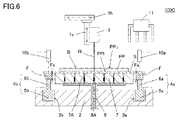
- FIG. 6 is a cross-sectional view of a direct drawing type exposure apparatus 100C according to a third modification.
- the third modification as in the second modification, the upper surface of the support member 7 and the lower surface central region of the heel S described in the embodiment of the direct drawing type exposure apparatus 100 according to the present invention described above are in close contact with each other. Thus, a configuration for reliably detecting the contact state is added. Therefore, since other parts are the same as those of the direct drawing type exposure apparatus 100 according to the present invention described above, description thereof will be omitted.
- the direct-drawing exposure apparatus 100C according to the third modification example has a base material B corresponding to locations supported by drive shafts 6a to 6d (drive shafts 6c and 6d are not shown) on the lower surface of the base material B.
- the distance detection part which each detects the distance to the upper surface of each, and the control apparatus 11 are further provided.
- the distance detection unit 10a is provided at a position that can detect the distance to the upper surface of the base material B, corresponding to the location supported by the drive shaft 6a on the lower surface of the base material B. And it is connected to the control device 11.
- the connection state is represented by a dotted line.
- the distance detection unit 10 a is provided so that its detection axis (one-dot chain line) and the central axis of the drive shaft 6 a are the same.
- the control apparatus 11 is connected with the drive part 5a so that an operation command can be given to the drive part 5a based on the information from the distance detection part 10a.
- the distance detectors 10b to 10d are also provided at positions corresponding to the drive shafts 6b to 6d, respectively, and connected to the control device 11 in the same manner as the distance detector 10a. Has been.
- the distance detectors 10b to 10d are provided so that their detection axes (one-dot chain lines) are the same as the central axes of the corresponding drive shafts 6b to 6d.
- the control device 11 is connected to each of the drive units 5b to 5d in the same manner as described above.
- the control device 11 detects each distance detection unit based on information from the distance detection units 10a to 10d indicating that the distance between each distance detection unit and the upper surface of the base material B has increased to a predetermined value. Control is performed so as to give an operation command to stop the operation to the corresponding drive unit.
- a laser displacement meter can be preferably used as the distance detectors 10a to 10d.
- the distance between the distance detectors 10a to 10d and the upper surface of the base material B is a predetermined distance as a result of the displacement mechanisms 4a to 4d displacing the base material B.
- the distance detectors 10a to 10d detect that the value has increased to the value.
- the information is transmitted to the control device 11, and the control device 11 gives an operation command to stop the operation to the drive unit corresponding to the distance detection unit that transmitted the information.
- the displacement mechanisms 4a to 4d are configured to be able to operate independently.
- the predetermined value is a distance between each of the distance detection units 10a to 10d and the upper surface of the base material B when the upper surface of the support member 7 and the lower surface central region of the base material B are in contact with each other. It is preferable that
- control device 11 controls the corresponding drive unit to give an operation command to stop the operation.
- the drive shafts 6a to 6d may each include a rigid body portion and an elastic deformation portion (the above-described first embodiment). (See the direct-drawing type exposure apparatus 100A according to a modification).
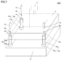
- FIG. 7 is a perspective view of the direct drawing type exposure apparatus 100D according to the fourth modified example seen through the base 2 simplified in illustration.
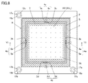
- FIG. 8 is a top view of the main part of the direct drawing type exposure apparatus 100D according to the third modification.
- a mechanism for adjusting the inclination generated for some reason is added to the base 2. Therefore, since other parts are the same as those of the direct drawing type exposure apparatus 100 according to the present invention described above, description thereof will be omitted.
- the recesses 3a to 3d illustrated in FIG. 1, the drive units 5a to 5d installed in the corresponding recesses, the stem 8, and the like are also omitted.
- the direct drawing type exposure apparatus 100D further includes tilt adjustment mechanisms 14a to 14c, tilt detection mechanisms 17a to 17c, and a control device 11.
- the inclination adjusting mechanisms 14a to 14c are installed on the upper surface of the pedestal 13, and include a drive unit and a drive shaft that is displaced by the drive unit.
- the inclination adjustment mechanism 14a includes a drive unit 15a and a drive shaft 16a that is displaced by the drive unit 15a.
- the inclination adjustment mechanisms 14b and 14c have the same configuration as the inclination adjustment mechanism 14a, and include a drive unit 15b, a drive shaft 16b, a drive unit 15c, and a drive shaft 16c, respectively.
- the tilt adjusting mechanisms 14a to 14c are not limited to the above-described mechanisms, and any mechanism can be used as long as the tilt can be adjusted to an arbitrary angle.
- a biaxial tilt stage or tilt unit can be used.
- the drive shafts 16a to 16c are inserted into recesses 12a to 12c provided on the lower surface of the base 2, respectively, and support the base 2 by coming into contact with the top surfaces of the recesses 12a to 12c.
- the illustration of the drive units 15a to 15c is omitted.
- a cylinder stroke adjustment mechanism by pneumatic pressure or hydraulic pressure a linear motion mechanism by a ball screw connected to a servo motor, a stepping motor with a lead screw, or the like can be preferably used.
- each of the inclination detection mechanisms 17a to 17c irradiates predetermined detection spots 18a to 18c on the substrate 2 with laser light, and measures the distance between the base 2 and the inclination detection mechanisms 17a to 17c.
- the control device 11 detects the inclination of the base 2 by comparing the distances of the three points obtained by the inclination detection mechanisms 17a to 17c with each other. Then, control is performed so that an operation command for adjusting the tilt angle of the base 2 is given to the tilt adjusting mechanisms 14a to 14c.
- FIG. 7 shows the tilt adjusting mechanisms 14a to 14c through the base 2, and shows the positional relationship between the tilt adjusting mechanisms 14a to 14c and the tilt detecting mechanisms 17a to 17c.
- the inclination detection mechanism 17a, the detection spot 18a, and the inclination adjustment mechanism 14a are configured to be on the same axis.
- the arrangement relationship between the tilt detection mechanism, the detection spot, and the tilt adjustment mechanism at other positions is the same. That is, the inclination detection mechanism 17b, the detection spot 18b, and the inclination adjustment mechanism 14b are on the same axis, and the inclination detection mechanism 17c, the detection spot 18c, and the inclination adjustment mechanism 14c are on the same axis. Note that the tilt detection mechanism and the detection spot and the corresponding tilt adjustment mechanism do not have to exist on the same axis.
- the tilt detection mechanisms are arranged at three locations to detect the tilt of the base 2, and the tilt angle of the base 2 is adjusted by the corresponding three tilt adjustment mechanisms.
- the control device 11 adjusts the inclination angle of the base 2 by operating the inclination adjustment mechanisms 14a to 14c based on information from the inclination detection mechanisms 17a to 17c.
- the inclination angle thereof can be adjusted by adjusting the inclination angle of the base 2.
- the optical axis of the exposure light beam 1b is adjusted in a state where the upper surface of the support member 7 and the lower surface central region of the base material B are brought into contact with each other by adjusting the inclination angle of the base 2. It can adjust so that the angle with the upper surface of the base material B may become orthogonal. That is, by performing exposure in this state, a more accurate opening pattern can be obtained.
- 100, 100A to 100D Direct drawing type exposure apparatus, 1 light source, 1b exposure light beam, 2 base, 4a to 4d displacement mechanism, 5a to 5d drive part, 6a to 6d drive shaft, 6ae to 6de elastic deformation part, 7 support member 9a to 9d, load detection unit, 10a to 10d, distance detection unit, 11 control device, B base material, PP photosensitive resin.
Landscapes
- Engineering & Computer Science (AREA)
- Manufacturing & Machinery (AREA)
- Physics & Mathematics (AREA)
- General Physics & Mathematics (AREA)
- Microelectronics & Electronic Packaging (AREA)
- Exposure And Positioning Against Photoresist Photosensitive Materials (AREA)
- Container, Conveyance, Adherence, Positioning, Of Wafer (AREA)
- Manufacture Or Reproduction Of Printing Formes (AREA)
Abstract
直描型露光装置(100)は、基材(B)に保持された膜状の感光性樹脂(PP)に、露光光線(1b)を直接照射することによりパターン露光を行なうものであって、露光光線(1b)を出力する光源(1)と、基台(2)と、基材(B)の下面周縁領域を支持可能であり、かつ露光光線(1b)の光軸方向において基材(B)を変位させるように動作する変位機構(4a~4d)と、基材(B)の下面中央領域を支持可能な支持部材(7)とを備える。支持部材(7)は、変位機構(4a~4d)により基材(B)を変位させて、支持部材(7)の上面と基材(B)の下面中央領域とを当接させた状態において、露光光線(1b)の光軸と支持部材(7)の上面とが直交するように、基台(2)の上方に配設される。
Description
この発明は、紫外線領域の波長を有する光線を、マスクを介さず感光性樹脂に直接照射して、所定のパターンを描画することにより、感光性樹脂をパターン露光する直描型露光装置に関するものである。
電子部品の製造における配線パターンおよび電極パターンの形成には、スクリーン印刷が利用されることが多い。
スクリーン印刷は、所定の開口パターンを有するように製版された紗と呼ばれる網目の布が枠体に張られてなるスクリーン印刷版を通して、印刷対象物にインクを印刷する技術である。
スクリーン印刷版の製版は、紗に感光性樹脂を塗布し、マスク(原版)を介して紫外線などを照射して露光した後、不要な部分を洗浄除去(現像)して、所定の開口パターンを得ることにより行なわれている。
ところで、近年、紫外線領域の波長を有する露光光線を、マスクを介さず感光性樹脂に直接照射して、所定のパターンを描画することにより、感光性樹脂をパターン露光する直描型露光装置が普及し始めている。
そのような直描型露光装置の一例として、例えば特開平11-320968号公報(特許文献1)では、デジタル・マイクロミラー・デバイス(以下、DMDと呼称)を用いてパターン露光を行なう直描型露光装置が提案されている。
図9は、上記公報に記載されている直描型露光装置200の説明図である。図9(A)は、直描型露光装置200の概略構成図である。図9(B)は、直描型露光装置200に用いられているDMD205のミラー構成を示す模式図である。図9(C)は、図9(B)の部分拡大図である。
図9(B)に示すように、DMD205は、正方形の微小ミラーMが横方向(図9(B)の左右方向であって、微小ミラーMが列をなす方向)にm個、縦方向(図9(B)の上下方向であって、微小ミラーMの列が並ぶ方向)に6列配置されてなる。横方向において、互いに隣接する微小ミラーMの間には、隙間gが設けられている。各列(M11~M16)の微小ミラーMは、隣接する上下の列における微小ミラーMとそれぞれ所定の距離だけずらせて配置されている。
図9(A)に示すように、露光対象物である感光性樹脂PPは、膜状であって、例えば樹脂単体のドライフィルムの状態で、または液状の樹脂を不図示の基材上に塗布後、乾燥させた状態で、テーブル203に載置される。テーブル203は、ベース202上をY方向に移動自在である。
そして、図9(C)に示すように、各微小ミラーMは、一対の端部Maを結ぶ対角線を回転軸として、端部Mbが回転可能となるように構成されている。DMD制御装置206は、DMD205の各微小ミラーMの回転を個別に制御する。
光源201から出力された紫外線領域の波長を有する光は、コリメーターレンズ204により平行光201aに変換されてDMD205に入射する。そして、平行光201aは、入射した各微小ミラーMがどのように回転されているかにより、各ミラーMによる反射光の方向が決められる。
幾つかの微小ミラーMによる反射光は、マイクロレンズ207により集光されることにより、露光光線201bとなって感光性樹脂PPの露光面に照射され、露光に寄与する。一方、別の微小ミラーMによる反射光は、感光性樹脂PPから離れた位置に照射され、露光に寄与しない。
すなわち、直描型露光装置200では、DMD205の微小ミラーMの個別の回転角を制御することにより、感光性樹脂PPをパターン露光することができる。
ここで、図10(A)に示すように、液状の感光性樹脂PPを枠体Fに張られた紗S上に塗布後、乾燥させたスクリーン印刷版を、直描型露光装置200によりパターン露光することを考える。
上記のスクリーン印刷版において、液状の感光性樹脂PPの紗S上への塗布は、均一な膜厚で、図上での上面PPuと下面PPlとが平行となるように行なわれているが、枠体Fの厚みが均一ではなかったとする。
このようなスクリーン印刷版を、上面PPuを露光面としてテーブル203に載置すると、枠体Fに張られた紗Sは、テーブル203の上面に対してわずかに傾斜する。その傾斜角をθとすると、露光光線201bの光軸201cと上面PPuとは直交せず、露光光線201bの光軸201cに対して、上面PPuの法線方向PPnが角度θだけ傾くことになる。
その状態で露光した後、現像すると、図10(B)に示すように、上面PPuの法線方向PPnに対して角度θだけ傾き、上面PPu側の開口位置Auと下面PPl側の開口位置Alとがずれた開口パターンが形成されてしまう。
スクリーン印刷は、図10(A)における感光性樹脂の上面PPuが印刷対象物に接するようにして行なわれる。一方、印刷対象物との位置合わせは下面PPl側から行なう。上面PPu側と下面PPl側とで開口位置がずれていると、下面PPl側の開口位置で位置合わせを行なっても、実際に印刷対象物にインクが印刷されるのは上面PPu側の開口位置となり、印刷ずれが生じることになる。
また、露光光線201bの光軸201cと上面PPuとが直交していない場合、露光光線201bの上面PPu上における投影像は、直交からのずれに応じて歪むことになる。例えば、露光光線201bの光軸201cに直交する断面が円形であったとすると、上面PPu上では、楕円形に歪んでしまう。露光光線201bの上面PPu上における投影像が歪みを有すると、開口パターンとしても歪みが生じることになる。
そこで、この発明の目的は、感光性樹脂を支持する基材の厚みが不均一であったとしても、露光光線の光軸が感光性樹脂の露光面に対して常に直交する状態でパターン露光ができる直描型露光装置を提供することである。
この発明では、露光光線の光軸が感光性樹脂の露光面に対して直交する状態でパターン露光を行なうことができるようにするため、露光時における感光性樹脂を支持する基材の高さ位置を決める機構についての改良が図られる。
この発明に係る直描型露光装置は、下記の構成により、板状の基材に保持された膜状の感光性樹脂に、露光光線を所定のパターンで直接照射することによりパターン露光を行なう。
この発明に係る直描型露光装置は、露光光線を出力する光源と、基台と、駆動部および駆動軸を含む複数の変位機構と、基材の下面中央領域を支持可能な支持部材と、を備える。
複数の変位機構は、基材の下面周縁領域を支持可能であり、かつ露光光線の光軸方向において基材を変位させるように動作する。支持部材は、複数の変位機構により基材を変位させて、支持部材の上面と基材の下面中央領域とを当接させた状態において、露光光線の光軸と支持部材の上面とが直交するように、基台の上方に配設されている。
上記の直描型露光装置では、複数の変位機構が基材を変位させ、支持部材の上面と基材の下面中央領域とを当接させた状態において、露光光線の光軸と基材の上面とが直交している。
そのため、露光光線の光軸が、基材の上面に設けられている感光性樹脂の上面(露光面)に対して、許容できる誤差範囲内において常に直交する状態で、パターン露光を行なうことができる。
すなわち、感光性樹脂の上面側と下面(位置合わせ面)側とで、開口パターンの開口位置がずれることがない。また、開口パターンの歪みも生じることがない。
したがって、感光性樹脂をスクリーン印刷版などの印刷版に用いた場合、高精度の開口パターンを得ることができるため、位置合わせを行なった所望の箇所に、高精度でインクを印刷することができる。
この発明に係る直描型露光装置における第1の好ましい実施形態は、駆動軸が軸方向の応力に対して弾性変形する弾性変形部を有する。
基材は初期位置においてその重量により弾性変形部を変形させた状態で、変位機構の駆動軸により支持されている。
上記の直描型露光装置では、支持部材の上面と基材の下面中央領域とが当接することにより、基材の重量の少なくとも一部を支持部材が受けるようになる。その結果、駆動軸の弾性変形部は、軸方向にかかる荷重が低減する分、元の形状に戻るように逆変形する。
そのため、支持部材の上面と基材の下面中央領域とが当接した後に、変位機構がさらに少し基材を変位させたとしても、弾性変形部が少し逆変形するだけで、変位機構は基材を支持し続ける。すなわち、基材が急に支持部材のみによって支持されるようになることが避けられる。
例えば、基材として、前述のように紗と呼ばれる網目の布が枠体に張られてなるものが用いられ、枠体が駆動軸によって支持されておらず、紗の下面中央領域が支持部材によって支持されている状態を考える。この状態では、紗は枠体の重量によって引っ張られ、弾性変形する可能性がある。
紗の弾性変形が無視できない場合、弾性変形した状態で露光したとすると、弾性変形が解除されることにより露光パターンは変形し、所望の開口パターンとは異なるものとなってしまう。
一方、上記のように弾性変形部が元の形状に戻るまで、枠体が引き続き駆動軸によって支持されている状態を考える。この状態では、紗にはごくわずかしか枠体の重量がかからないため、紗はほとんど引っ張られない。すなわち、紗に無視できない弾性変形が発生することがない。その結果、露光パターンと現像後の開口パターンとを、高精度で一致させることができる。
したがって、その状態で感光性樹脂を露光することにより、さらに高精度な開口パターンを得ることができる。
この発明に係る直描型露光装置における第2の好ましい実施形態は、駆動軸に接続され、駆動軸の軸方向にかかる荷重を検知する荷重検知部と、制御装置とをさらに備える。
制御装置は、荷重検知部が検知する荷重が、所定の値まで減少したことを伝える情報に基づいて、駆動部に動作を停止する動作指令を与えるように制御する。
上記の直描型露光装置では、基材が支持部材に当接することにより、基材の重量の少なくとも一部を支持部材が受けるようになった結果、駆動軸にかかる荷重が、所定の値まで減少したことを荷重検知部で検知する。その情報は制御装置に送信され、制御装置はその情報に基づいて、駆動部に動作を停止する動作指令を与える。
言い換えると、変位機構は、駆動軸にかかる荷重が所定の値まで減少したことを荷重検知部が検知するまで、基材を確実に変位させる。したがって、支持部材の上面と基材の下面中央領域とを確実に当接させ、露光光線の光軸と支持部材の上面とを確実に直交させることができる。
なお、基材が支持部材に当接すると、当接箇所の近傍にある荷重検知部が検知する荷重は急激に減少する。そして、基材が当接箇所の近くにある駆動軸から離れると、その駆動軸にかかる荷重は検知されなくなる。したがって、上記の所定の値は、基材が支持部材に当接する前に荷重検知部が検知していた荷重値の80~99%程度の荷重値であることが好ましい。
また、上記の直描型露光装置では、駆動軸にかかる荷重の減少が始まったことを荷重検知部が検知した時点で、制御装置が駆動部に動作を停止する動作指令を与えるように制御することにより、駆動部が駆動軸を変位させ過ぎずに済む。すなわち、第1の好ましい実施形態と同様に、基材が支持部材のみによって支持されることを避けることができる。
例えば、基材として、前述のように紗が枠体に張られてなるものが用いられ、初期位置では枠体が変位機構の駆動軸によって支持されている状態を考える。そして、駆動軸にかかる荷重の減少開始を荷重検知部が検知した時点で、制御装置が駆動部に動作を停止させ、枠体が引き続き駆動軸によって支持されるようにする。この状態では、第1の好ましい実施形態のように紗はほとんど引っ張られない。すなわち、紗に無視できない弾性変形が発生することがない。
また、全ての荷重検知部において荷重の減少を検知し、全ての駆動部が動作を停止した状態では、支持部材の上面と紗の下面中央領域とが当接し、露光光線の光軸と紗の上面とは直交している。この状態では、紗の上面に塗布されている感光性樹脂の露光面は、露光光線の光軸に対して傾いていない。その結果、露光パターンと現像後の開口パターンとを、高精度で一致させることができる。
したがって、第1の好ましい実施形態と同様に、さらに高精度な開口パターンを得ることができる。
この発明に係る直描型露光装置における第3の好ましい実施形態は、基材の下面周縁領域の駆動軸により支持されている箇所に対応する、基材の上面までの距離を検出する距離検知部と、制御装置とをさらに備える。
制御装置は、距離検知部からの、距離検知部と基材の上面との間の距離が所定の値まで増加したことを伝える情報に基づいて、駆動部に動作を停止する動作指令を与えるように制御する。
上記の直描型露光装置では、複数の変位機構が基材を変位させた結果、距離検知部と基材の上面との間の距離が所定の値まで増加したことを距離検出部で検知する。その情報は制御装置に送信され、制御装置はその情報に基づいて、駆動部に動作を停止する動作指令を与える。
言い換えると、変位機構は、距離検知部と基材の上面との間の距離が所定の値まで増加したことを距離検知部が検知するまで、基材を確実に変位させる。したがって、支持部材の上面と基材の下面中央領域との当接、および基材の下面周縁領域と駆動軸との当接を両立させ、露光光線の光軸と支持部材の上面とを確実に直交させることができる。
また、上記の所定の値は、支持部材の上面と基材の下面中央領域とが当接した時点での、距離検知部と基材の上面との間の距離であることが好ましい。上記の直描型露光装置では、距離検知部が検知する距離がその値となった時点で、制御装置が駆動部に動作を停止する動作指令を与えるように制御することにより、駆動部が駆動軸を変位させ過ぎずに済む。すなわち、第1および第2の好ましい実施形態と同様に、基材が支持部材のみによって支持されることを避けることができる。
例えば、前述したように、基材として、紗が枠体に張られてなるものが用いられ、初期位置では枠体が変位機構の駆動軸によって支持されている状態を考える。そして、駆動軸を駆動部により変位させ、距離検知部が検知する距離が上記の所定の値となった時点で制御装置が駆動部に動作を停止させ、枠体が引き続き駆動軸によって支持されるようにする。この状態では、第1の好ましい実施形態のように紗はほとんど引っ張られない。すなわち、紗に無視できない弾性変形が発生することがない。
また、全ての距離検知部の検知する距離が所定の距離となり、全ての駆動部が動作を停止した状態では、支持部材の上面と紗の下面中央領域とが当接し、露光光線の光軸と紗の上面とは直交している。この状態では、紗の上面に塗布されている感光性樹脂の露光面は、露光光線の光軸に対して傾いていない。その結果、露光パターンと現像後の開口パターンとを、高精度で一致させることができる。
したがって、第1および第2の好ましい実施形態と同様に、さらに高精度な開口パターンを得ることができる。
この発明に係る直描型露光装置における第4の好ましい実施形態では、傾斜検知機構と、傾斜調整機構とをさらに備える。制御装置は、傾斜検知機構による情報に基づいて、基台の傾斜角を調整する動作指令を、傾斜調整機構に与えるように制御する。
上記の直描型露光装置では、制御装置は、傾斜検知機構による情報に基づいて傾斜調整機構を動作させることにより、基台の傾斜角を調整している。
支持部材は基台上に設置されているので、その傾斜角は、基台の傾斜角を調整することで調整することができる。
したがって、基台の傾斜角を調整することにより、支持部材の上面と基材の下面中央領域とを当接させた状態において、露光光線の光軸と基材の上面との角度が直交となるように調整することができる。すなわち、その状態で露光することにより、さらに高精度な開口パターンを得ることができる。
この発明に係る直描型露光装置では、支持部材の上面と基材の下面中央領域とを当接させた状態において、露光光線の光軸と基材の上面とが直交している。
そのため、露光光線の光軸が、基材の上面に設けられている感光性樹脂の上面(露光面)に対して、許容できる誤差範囲内において常に直交する状態で、パターン露光を行なうことができる。
すなわち、感光性樹脂の上面側と下面(位置合わせ面)側とで、開口パターンの開口位置がずれることがない。また、開口パターンの歪みも生じることがない。
したがって、感光性樹脂をスクリーン印刷版などの印刷版に用いた場合、高精度の開口パターンを得ることができるため、位置合わせを行なった所望の箇所に、高精度でインクを印刷することができる。
以下にこの発明の実施形態を示して、本発明の特徴とするところをさらに詳しく説明する。
<この発明に係る直描型露光装置の実施形態>
この発明に係る直描型露光装置の実施形態について、図1および図2を用いて説明する。
この発明に係る直描型露光装置の実施形態について、図1および図2を用いて説明する。
図1は、この実施形態に係る直描型露光装置100の断面図である。図2は、この実施形態に係る直描型露光装置100の要部の上面図である。図1は、図2のY1-Y1線を含む面の矢視断面図となっている。
図1および図2を参照して、この実施形態に係る直描型露光装置100は、下記の構成により、板状の基材Bの上面に保持された膜状の感光性樹脂PPに、露光光線1bを所定のパターンで直接照射することによりパターン露光を行なう。
図1では、基材Bとして、前述のように紗Sと呼ばれる網目の布が枠体Fに張られてなるものが用いられている。基材Bには、任意の材質の板状部材など、所望のものを用いることができる。感光性樹脂PPも、前述のように、膜状であって、例えば樹脂単体のドライフィルムの状態のものや、液状の樹脂を紗S上に塗布後、乾燥させた状態のものなど、所望のものを用いることができる。
なお、感光性樹脂PPの厚みの不均一は無視できるものとし、上面PPu(露光面)は、基材B(紗S)の上面と実質的に平行となっているとする。
直描型露光装置100は、光源1と、基台2と、変位機構4a~4dと、支持部材7とを含む。
光源1は、露光光線1bを出力する。露光光線1bは、感光性樹脂PPに化学変化を生じさせる波長を有する光線である。そのための光源1の発光体としては、例えば紫外線レーザー、超高圧水銀ランプ、またはLEDなど、紫外線領域の波長を有する光を発するものを用いることができる。光源1は、コリメーターレンズや集光レンズなどのレンズ系をさらに含んでもよい。
図1では、光源1は、水平移動機構1hと上下移動機構1vにより、水平方向および上下方向に移動可能となっている。すなわち、図1では、基台2を動かさず、水平移動機構1hにより光源1を水平移動させてパターン露光を行なう。また、上下移動機構1vにより光源1を上下移動させて焦点位置の調節を行なう。
なお、パターン露光を行なうためには、光源1を移動させずに、上記特開平11-320968号公報に記載のDMDや、ガルバノミラーなどの反射鏡を用いることにより、露光光線の照射位置を変えるようにしてもよい。また、別途設けた水平移動機構および上下移動機構の少なくとも一方により、基台2を水平方向および垂直方向の少なくとも一方に移動させてパターン露光を行なうようにしてもよい。
基台2は、特に形状の限定はなく、平板状のものであっても、底部と側壁とにより形成される凹部を備えるものであってもよい。この実施形態に係る直描型露光装置100では、後述の変位機構4a~4dをそれぞれ駆動させる駆動部5a~5dは、基台2の上面に設けられた凹部3a~3d内にそれぞれ設置される。例えば、駆動部5aは凹部3a内に設置される。駆動部5b~5dも、駆動部5aと同様に、それぞれ対応する凹部3b~3d内に設置される。なお、駆動部5a~5dは、凹部3a~3dの設けられていない平板状の基台2の上面に設置されるようにしてもよい。
変位機構4a~4dは、駆動部と、駆動部により変位する駆動軸とを備える。例えば、変位機構4aは、駆動部5aと、駆動部5aにより変位する駆動軸6aとを備える。変位機構4b~4dも、変位機構4aと同様の構成であり、それぞれ駆動部5bおよび駆動軸6b、駆動部5cおよび駆動軸6c、駆動軸5dおよび駆動軸6dを備える。駆動部5a~5dは、前述のように、基台2の上面に設けられた、対応する凹部3a~3d内にそれぞれ設置されている。
駆動部5a~5dとしては、例えば空圧または油圧によるシリンダーストローク調整機構、サーボモータに接続されたボールねじによる直動機構、およびリードスクリュー付きのステッピングモータなどを好ましく用いることができる。また、駆動部と駆動軸との位置関係は、図1に示したものに限らず、例えば駆動軸が基台2の上面に設置され、その駆動軸上を駆動部が移動するリニアモータのようなものでもよい。
変位機構4a~4dは、それぞれが備える駆動軸により、基材Bの下面周縁領域を支持することができる。さらに、変位機構4a~4dは、駆動軸を、それぞれが接続される駆動部により駆動させることにより、基材Bを露光光線1bの光軸方向において変位させる。
すなわち、変位機構4a~4dを動作させて基材Bを変位させることにより、後述の支持部材7の上面と基材Bの下面中央領域とを当接させた状態とすることができる。
この実施形態に係る直描型露光装置100においては、変位機構4a~4dは、それぞれが独立して動作することができるように構成されている。なお、駆動部5a~5dは、所定の位置で、接続されている駆動軸の駆動を停止し、その状態を維持できるように(ホールド状態となるように)設定されている。
支持部材7は、支持部材7の上面と基材Bの下面中央領域とを当接させた状態において、露光光線1bの光軸と支持部材7の上面とが、許容できる誤差範囲内において直交するように、ステム8により基台2の上方の所定の高さに配設されている。また、ステム8の内部には、空気通路8Aが設けられている。
また、支持部材7は、その上面に開口する空気通路7Aをその内部に有している。この空気通路7Aは、ステム8の鍔部8Gと支持部材7の下面に設けられた凹部とにより形成される空気室7Rおよび空気通路8Aを通じて不図示の減圧機構に連通している。このような構成により、支持部材7の上面は、基材Bの下面中央領域を減圧吸着可能となっている。
この実施形態に係る直描型露光装置100では、上記の構成を有するため、支持部材7の上面と基材Bの下面中央領域とが密着した状態で、基材Bの下面中央領域が、支持部材7により吸着固定される。
したがって、この状態では、支持部材7の上面と基材Bの上面に保持された感光性樹脂PPの上面PPu(露光面)とが平行となっている。
次に、変位機構4a~4dおよび支持部材7による、露光時における基材Bの高さ位置の位置決めについて、図3を用いて説明する。
具体例として、基材Bが枠体Fとそれに張られた紗Sを含むスクリーン印刷版であって、枠体Fの厚みが不均一な場合を考える。説明を簡略化するため、変位機構4aおよび4bにより、基材Bを露光光線1bの光軸方向において変位させるものとする。実際には、変位機構4cおよび4dも含めて、基材Bを露光光線1bの光軸方向において変位させ、露光時における基材Bの高さ位置の位置決めを行なう。
ここで、枠体Fの、変位機構4aで変位させられる箇所の厚み(Fa)が、変位機構4bで変位させられる箇所の厚み(Fb)より厚いとする(図9(A)も参照)。
また、支持部材7は、前述のように、支持部材7の上面と基材Bの下面中央領域とを当接させた状態において、露光光線1bの光軸と支持部材7の上面とが、許容できる誤差範囲内において直交するように、ステム8により基台2の上方の所定の高さに配設されている。
図3(A)は、そのような基材Bの下面周縁領域を支持している変位機構の4aおよび4bのそれぞれの駆動軸6aおよび6bが、初期位置(変位機構4aおよび4bが動作する前の位置)にある状態を表わす断面図である。なお、初期位置において、駆動軸6aおよび6bの枠体Fに当接している端部の、基台2の上面からの高さ位置Hは同一である。
したがって、枠体Fに張られた紗Sの、駆動軸6bに近い部分Sbの高さ位置は、駆動軸6aに近い部分Saの高さ位置より低くなっている。すなわち、紗Sの駆動軸6bに近い部分Sbは、駆動軸6aに近い部分Saより、支持部材7に近くなっている。したがって、露光光線1bの光軸1cに対して、感光性樹脂PPの上面PPuの法線方向PPnは角度θだけ傾いている。
図3(B)は、変位機構4aおよび4bが動作して、枠体Fが変位することにより、紗Sの駆動軸6bに近い部分Sbが、支持部材7の上面に当接した状態を表わす断面図である。
図3(A)の状態から駆動軸6aおよび6bが変位すると、紗Sの駆動軸6bに近い部分Sbが、支持部材7の上面に、FaとFbとの厚みの差の分だけ先に当接する。この時点で変位機構4bの駆動部5bの動作を停止させ、変位機構4bをホールド状態とする。したがって、枠体Fは、引き続き駆動軸6bによっても支持されている。
一方、この時点では、紗Sの駆動軸6aに近い部分Saは、支持部材7の上面にまだ当接していない。変位機構4aおよび4bは独立して動作することができるように構成されているため、変位機構4bがホールド状態になっても、変位機構4aは枠体Fを変位させる動作を続けている。
図3(C)は、変位機構4aが引き続き動作し、駆動軸6aがさらに変位することにより、紗Sの駆動軸6aに近い部分Saも支持部材7の上面に当接した状態を表わす断面図である。その結果、支持部材7の上面と紗Sの下面中央領域とが密着して当接する。
図3(B)の状態から枠体Fの駆動軸6aによって支持されている箇所が変位すると、紗Sの駆動軸6aに近い部分Saも、支持部材7の上面にやがて当接する。この時点で変位機構4aの駆動部5aの動作を停止させ、変位機構4aをホールド状態とする。したがって、枠体Fは、引き続き駆動軸6aによっても支持されている。
以上の段階を経ることにより、この実施形態に係る直描型露光装置100では、支持部材7の上面と紗Sの下面中央領域とが密着して当接するように、基材Bの高さ位置が位置決めされる。この状態では、支持部材7の上面と紗Sの上面に保持された感光性樹脂PPの上面PPu(露光面)とが平行となっている。したがって、上記の状態では、感光性樹脂PPの上面PPu(露光面)は、露光光線1bの光軸と、許容できる誤差範囲内において直交する高さ位置となっている。
さらに、基材Bの高さ位置が位置決めされた後も、枠体Fは駆動軸6aおよび6bによって引き続き支持されている。この状態では、紗にはごくわずかしか枠体の重量がかからないため、紗はほとんど引っ張られない。
なお、上記の説明では、紗Sの弾性変形を考慮して、変位機構4aおよび4bは独立して動作し、基材Bの高さ位置が位置決めされた後も、枠体Fは駆動軸6aおよび6bによって支持され続けるとした。一方、例えば枠体Fの重量が軽く、枠体Fの重量による紗Sの弾性変形が無視できるような場合は、駆動軸6aおよび6bが枠体Fの下面から離れるまで変位し、基材Bが支持部材7のみによって支持されるようにしてもよい。この場合、変位機構4aおよび4bは、それぞれが連動して動作することができるように構成することができる。
なお、このことは、基材Bが例えば剛性の高い板状部材などからなり、仮に枠体Fの重量がかかっても、本質的に弾性変形し難いものである場合についても同様である。
上記の具体例から分かるように、この実施形態に係る直描型露光装置100では、基材Bの厚みが不均一であっても、上記の基材Bの下面中央領域と支持部材7の上面とを当接させた状態において、露光光線1bの光軸と基材Bの上面とは、確実に直交することになる。そのため、露光光線1bの光軸が感光性樹脂PPの上面PPu(露光面)に対して直交する状態で、パターン露光を行なうことができる。
また、基材Bの重量を駆動軸6a~6dが十分支えることにより、紗Sに無視できない弾性変形が発生することがないため、その上面に保持されている感光性樹脂PPも、弾性変形のない状態となる。その結果、露光パターンと現像後の開口パターンとを、高精度で一致させることができる。
したがって、この実施形態に係る直描型露光装置100では、感光性樹脂PPの上面PPu側と下面PPl側とで、開口パターンの開口位置がずれることがない。また、開口パターンの歪みも生じることがないため、高精度な開口パターンを得ることができる。すなわち、感光性樹脂PPをスクリーン印刷版などの印刷版に用いた場合、位置合わせを行なった所望の箇所に、高精度でインクを印刷することができる。また、印刷パターンの寸法ばらつきを小さくすることができる。
<この発明に係る直描型露光装置の実施形態の第1の変形例>
上記の実施形態の第1の変形例に係る直描型露光装置100Aについて、図4を用いて説明する。
上記の実施形態の第1の変形例に係る直描型露光装置100Aについて、図4を用いて説明する。
図4は、第1の変形例に係る直描型露光装置100Aの断面図である。第1の変形例は、支持部材7上面と基材Bの下面中央領域とが当接した後に、基材Bが急に支持部材7のみによって支持されることを防止する構成を、駆動軸6a~6dに付加したものである。したがって、その他の部分については、前述のこの発明に係る直描型露光装置100と同様であるため、説明を省略する。
第1の変形例に係る直描型露光装置100Aは、駆動軸6a~6d(駆動軸6cおよび6dは不図示)がそれぞれ剛体部と弾性変形部とを備える。例えば、変位機構6aは、剛体部6asと、剛体部6asの端部に接続された弾性変形部6aeとを備える。駆動軸6b~6dも、駆動軸6aと同様の構成であり、それぞれ剛体部6bsおよび弾性変形部6be、剛体部6csおよび弾性変形部6ce、剛体部6dsおよび弾性変形部6deを備える。
弾性変形部6ae~6deとしては、例えばゴムおよびばねなどを好ましく用いることができる。また、駆動軸6a~6dにおける剛体部と弾性変形部との位置関係は、図4に示したものに限らず、例えば駆動軸が2本の剛体部を弾性変形部で接続したようなものでもよい。
前述のように、支持部材7の上面と基材Bの下面中央領域とが当接することにより、基材Bの重量の少なくとも一部を支持部材7が受けるようになる。
その結果、第1の変形例では、支持部材7の上面と基材Bの下面中央領域とが当接し、駆動軸6a~6dの軸方向にかかる荷重が低減する分、弾性変形部6ae~6deが元の形状に戻るように逆変形する。
そのため、支持部材7の上面と基材Bの下面中央領域とが当接した後に、変位機構4a~4dがさらに少し基材Bを変位させたとしても、弾性変形部6ae~6deが少し逆変形するだけで、変位機構4a~4dは基材Bを支持し続ける。すなわち、基材Bが急に支持部材7のみによって支持されるようになることが避けられる。
上記の構成においては、基材Bの高さ位置が位置決めされた後も、枠体Fは駆動軸6a~6dによって確実に支持され続ける。前述のように、紗Sが枠体Fの重量によって引っ張られると弾性変形する可能性がある場合であっても、上記の構成では、紗Sにはごくわずかしか枠体Fの重量がかからないため、紗Sはほとんど引っ張られない。
すなわち、紗Sに無視できない弾性変形が発生することがない。その結果、露光パターンと現像後の開口パターンとを、高精度で一致させることができる。
したがって、その状態で感光性樹脂PPを露光することにより、さらに高精度な開口パターンを得ることができる。
<この発明に係る直描型露光装置の実施形態の第2の変形例>
上記の実施形態の第2の変形例に係る直描型露光装置100Bについて、図5を用いて説明する。
上記の実施形態の第2の変形例に係る直描型露光装置100Bについて、図5を用いて説明する。
図5は、第2の変形例に係る直描型露光装置100Bの断面図である。第2の変形例は、前述のこの発明に係る直描型露光装置100の実施形態で説明した、支持部材7の上面と紗Sの下面中央領域とが密着して当接している状態を、確実に検知するための構成を付加したものである。したがって、その他の部分については、前述のこの発明に係る直描型露光装置100と同様であるため、説明を省略する。
第2の変形例に係る直描型露光装置100Bは、駆動軸6a~6d(駆動軸6cおよび6dは不図示)のそれぞれに接続され、駆動軸6a~6dのそれぞれにおける軸方向にかかる荷重を検知する荷重検知部と、荷重検知部および駆動部が接続される制御装置11とをさらに備える。
例えば、荷重検知部9aは、駆動軸6aの枠体Fに当接する端部に取り付けられており、かつ制御装置11と接続されている。図5では、その接続状態を点線で表わしている。また、制御装置11は、荷重検知部9aからの情報に基づいて、駆動部5aに動作指令を与えることができるように、駆動部5aと接続されている。
荷重検知部9b~9d(荷重検知部9cおよび9dは不図示)も、荷重検知部9aと同様に、それぞれ対応する駆動軸の端部に取り付けられており、かつそれぞれ制御装置11と接続されている。また、制御装置11は、上記と同様に、駆動部5b~5dのそれぞれと接続されている。
制御装置11は、荷重検知部9a~9dが検知する荷重が、所定の値まで減少したことを伝える情報に基づいて、それぞれの荷重検知部と対応する駆動部に、動作を停止する動作指令を与えるように制御する。
荷重検知部9a~9dとしては、例えば圧力センサおよびロードセルなどを好ましく用いることができる。また、駆動軸6a~6dにおける荷重検知部の取り付け位置は、図5に示したものに限らず、例えば2本の剛体部を荷重検知部で接続したようなものでもよい。
第2の変形例に係る直描型露光装置100Bでは、基材Bが支持部材7に当接することにより、基材Bの重量の少なくとも一部を支持部材7が受けるようになった結果、駆動軸6a~6dのそれぞれにかかる荷重が、所定の値まで減少したことを、駆動軸6a~6dにそれぞれ取り付けられている荷重検知部で検知する。
その情報は制御装置11に送信され、制御装置11は、情報を送信した荷重検知部に対応する駆動部に、動作を停止する動作指令を与える。この場合、変位機構4a~4dは、それぞれが独立して動作することができるように構成されているようにすることが好ましい。
なお、上記の所定の値は、基材が支持部材に当接する前に荷重検知部が検知していた荷重値の80~99%程度の荷重値であることが好ましい。
上記の構成では、駆動軸6a~6dにかかる荷重の減少が始まったことを、駆動軸6a~6dにそれぞれ取り付けられている荷重検知部が検知した時点で、制御装置12が、対応する駆動部に動作を停止する動作指令を与えるように制御する。
言い換えると、上記の構成により、前述の基材Bの高さ位置の位置決めの説明(図3参照)における、紗Sと支持部材7との当接の確認と、それに基づく変位機構4a~4dのそれぞれの駆動部の動作停止とが、自動的に行なわれる。
それにより、駆動部5a~5dが、それぞれに接続されている駆動軸を変位させ過ぎずに済む。すなわち、基材Bが支持部材7のみによって支持されることを避けることができる。
上記の構成においては、基材Bの高さ位置が位置決めされた後も、枠体Fは駆動軸6a~6dによって確実に支持され続ける。前述のように、紗Sが枠体Fの重量によって引っ張られると弾性変形する可能性がある場合であっても、上記の構成では、紗Sにはごくわずかしか枠体Fの重量がかからないため、紗Sはほとんど引っ張られない。
すなわち、紗Sに無視できない弾性変形が発生することがない。その結果、露光パターンと現像後の開口パターンとを、高精度で一致させることができる。
したがって、その状態で感光性樹脂PPを露光することにより、さらに高精度な開口パターンを得ることができる。
なお、この発明に係る直描型露光装置の実施形態の第2の変形例100Bは、駆動軸6a~6dがそれぞれ剛体部と弾性変形部とを備えるようにしてもよい(前述の第1の変形例に係る直描型露光装置100A参照)。
この場合、駆動軸6a~6dの変位により、基材Bが急に支持部材7のみによって支持されるようになることが避けられる。その結果、露光パターンと現像後の開口パターンとを、高精度で一致させることができる。
<この発明に係る直描型露光装置の実施形態の第3の変形例>
上記の実施形態の第3の変形例に係る直描型露光装置100Cについて、図6を用いて説明する。
上記の実施形態の第3の変形例に係る直描型露光装置100Cについて、図6を用いて説明する。
図6は、第3の変形例に係る直描型露光装置100Cの断面図である。第3の変形例も、第2の変形例と同様に、前述のこの発明に係る直描型露光装置100の実施形態で説明した、支持部材7の上面と紗Sの下面中央領域とが密着して当接している状態を、確実に検知するための構成を付加したものである。したがって、その他の部分については、前述のこの発明に係る直描型露光装置100と同様であるため、説明を省略する。
第3の変形例に係る直描型露光装置100Cは、基材Bの下面の駆動軸6a~6d(駆動軸6cおよび6dは不図示)によりそれぞれ支持されている箇所に対応する、基材Bの上面までの距離をそれぞれ検出する距離検知部と、制御装置11とをさらに備える。
例えば、距離検知部10aは、基材Bの下面の駆動軸6aにより支持されている箇所に対応する、基材Bの上面までの距離を検知することができるような位置に設けられており、かつ制御装置11と接続されている。図6では、その接続状態を点線で表わしている。なお、図6では、距離検知部10aは、その検知軸(一点鎖線)と、駆動軸6aの中心軸とが同一となるように設けられている。また、制御装置11は、距離検知部10aからの情報に基づいて、駆動部5aに動作指令を与えることができるように、駆動部5aと接続されている。
距離検知部10b~10d(距離検知部10cおよび10dは不図示)も、距離検知部10aと同様に、それぞれ駆動軸6b~6dに対応する位置に設けられており、かつそれぞれ制御装置11と接続されている。また、距離検知部10b~10dは、その検知軸(一点鎖線)と、それぞれ対応する駆動軸6b~6dの中心軸とが同一となるように設けられている。さらに、制御装置11は、上記と同様に、駆動部5b~5dのそれぞれと接続されている。
制御装置11は、距離検知部10a~10dからの、それぞれの距離検知部と基材Bの上面との間の距離が所定の値まで増加したことを伝える情報に基づいて、それぞれの距離検知部と対応する駆動部に、動作を停止する動作指令を与えるように制御する。
距離検知部10a~10dとしては、例えばレーザー変位計などを好ましく用いることができる。
第3の変形例に係る直描型露光装置100Cでは、変位機構4a~4dが基材Bを変位させた結果、距離検知部10a~10dと基材Bの上面との間の距離が所定の値まで増加したことを、距離検知部10a~10dで検知する。
その情報は制御装置11に送信され、制御装置11は、情報を送信した距離検知部に対応する駆動部に動作を停止する動作指令を与える。この場合、変位機構4a~4dは、それぞれが独立して動作することができるように構成されているようにすることが好ましい。
また、上記の所定の値は、支持部材7の上面と基材Bの下面中央領域とが当接した時点での、距離検知部10a~10dのそれぞれと基材Bの上面との間の距離であることが好ましい。
上記の構成においては、距離検知部10a~10dが検知する距離がその値となった時点で、制御装置11が、対応する駆動部に動作を停止する動作指令を与えるように制御する。
言い換えると、上記の構成により、前述の第2の変形例に係る直描型露光装置100Bと同様に、紗Sと支持部材7との当接の確認と、それに基づく変位機構4a~4dのそれぞれの駆動部の動作停止とが、自動的に行なわれる。
したがって、第2の変形例に係る直描型露光装置100Bと同様の効果が得られ、基材Bが引き続き駆動軸6a~6dによって支持されるようにした状態で露光することにより、さらに高精度な開口パターンを得ることができる。
なお、この発明に係る直描型露光装置の実施形態の第3の変形例100Cは、駆動軸6a~6dがそれぞれ剛体部と弾性変形部とを備えるようにしてもよい(前述の第1の変形例に係る直描型露光装置100A参照)。
この場合、駆動軸6a~6dの変位により、基材Bが急に支持部材7のみによって支持されるようになることが避けられる。その結果、露光パターンと現像後の開口パターンとを、高精度で一致させることができる。
<この発明に係る直描型露光装置の実施形態の第4の変形例>
上記の実施形態の第4の変形例に係る直描型露光装置100Dについて、図7および図8を用いて説明する。
上記の実施形態の第4の変形例に係る直描型露光装置100Dについて、図7および図8を用いて説明する。
図7は、第4の変形例に係る直描型露光装置100Dにおいて、図示を簡略化した基台2を透視した透視斜視図である。図8は、第3変形例に係る直描型露光装置100Dにおける要部の上面図である。第4の変形例は、基台2について、何らかの理由で発生した傾斜を調整する機構を追加したものである。したがって、その他の部分については、前述のこの発明に係る直描型露光装置100と同様であるため、説明を省略する。例えば、図7では、図1で図示した凹部3a~3d、対応する凹部内に設置された駆動部5a~5d、およびステム8などの図示も省略している。
第4の変形例では、直描型露光装置100Dは、傾斜調整機構14a~14cと、傾斜検知機構17a~17cと、制御装置11とをさらに備える。
傾斜調整機構14a~14cは、台座13の上面に設置されており、駆動部と、駆動部により変位する駆動軸とを備える。例えば、傾斜調整機構14aは、駆動部15aと、駆動部15aにより変位する駆動軸16aとを備える。傾斜調整機構14bおよび14cも、傾斜調整機構14aと同様の構成であり、それぞれ駆動部15bおよび駆動軸16b、駆動部15cおよび駆動軸16cを備える。
なお、傾斜調整機構14a~14cとしては、上記の機構に限らず、任意の角度に傾斜を調整できるものであればよい。例えば、2軸傾斜ステージや傾斜ユニットを用いることができる。
駆動軸16a~16cは、それぞれ基台2の下面に設けられた凹部12a~12cに挿入され、凹部12a~12c内の天面に当接することにより、基台2を支持している。なお、図8においては、駆動部15a~15cの図示を省略している。駆動部15a~15cとしては、例えば空圧または油圧によるシリンダーストローク調整機構、サーボモータに接続されたボールねじによる直動機構、およびリードスクリュー付きのステッピングモータなどを好ましく用いることができる。
傾斜検知機構17a~17cとしては、例えばレーザー変位計などを好ましく用いることができる。傾斜検知機構17a~17cのそれぞれは、基材2上の所定の検知スポット18a~18cにレーザー光を照射して、基台2と傾斜検知機構17a~17cとの間の距離を測定する。
制御装置11は、傾斜検知機構17a~17cにより得られた3点の距離を相互に比較することによって基台2の傾きを検知する。そして、基台2の傾斜角を調整する動作指令を、傾斜調整機構14a~14cに与えるように制御する。
図7では、基台2を透視して傾斜調整機構14a~14cを示し、傾斜調整機構14a~14cと傾斜検知機構17a~17cとの位置関係を示している。例えば、傾斜検知機構17aと検知スポット18aと傾斜調整機構14aとは、同一の軸線上にあるように構成されている。
その他の位置における傾斜検知機構と検知スポットと傾斜調整機構の配置関係も同様である。すなわち、傾斜検知機構17bと検知スポット18bと傾斜調整機構14bとが同一軸線上にあり、傾斜検知機構17cと検知スポット18cと傾斜調整機構14cとが同一軸線上にある。なお、傾斜検知機構および検知スポットと、対応する傾斜調整機構とは、同一軸線上に存在していなくてもよい。
また、図7および図8では、傾斜検知機構を3箇所に配置して基台2の傾きを検知し、対応する3つの傾斜調整機構により、基台2の傾斜角を調整しているが、傾斜検知機構および傾斜調整機構は、それぞれ3つ以上であればよい。さらに、傾斜検知機構および傾斜調整機構の数が異なっていてもよい。
制御装置11は、傾斜検知機構17a~17cによる情報に基づいて、傾斜調整機構14a~14cを動作させることにより、基台2の傾斜角を調整している。
支持部材7は、変位機構4a~4dにより基台2の上方に支持されているので、その傾斜角は、基台2の傾斜角を調整することで調整することができる。
したがって、第4の変形例では、基台2の傾斜角を調整することにより、支持部材7の上面と基材Bの下面中央領域とを当接させた状態において、露光光線1bの光軸と基材Bの上面との角度が直交となるように調整することができる。すなわち、その状態で露光することにより、さらに高精度な開口パターンを得ることができる。
なお、この発明は上記の実施形態に限定されるものではなく、この発明の範囲内において、種々の応用、変形を加えることが可能である。本発明の技術的範囲は請求の範囲によって画定され、また請求の範囲の記載と均等の意味および範囲内でのすべての変更を含むものである。
100,100A~100D 直描型露光装置、1 光源、1b 露光光線、2 基台、4a~4d 変位機構、5a~5d 駆動部、6a~6d 駆動軸、6ae~6de 弾性変形部、7 支持部材、9a~9d 荷重検知部、10a~10d 距離検知部、11 制御装置、B 基材、PP 感光性樹脂。
Claims (5)
- 板状の基材に保持された膜状の感光性樹脂に、露光光線を所定のパターンで直接照射することによりパターン露光を行なう直描型露光装置であって、
露光光線を出力する光源と、
基台と、
駆動部および駆動軸を含み、前記基材の下面周縁領域を支持可能であり、かつ前記露光光線の光軸方向において前記基材を変位させるように動作する複数の変位機構と、
前記基材の下面中央領域を支持可能な支持部材と、を備え、
前記支持部材は、前記複数の変位機構により前記基材を変位させて、前記支持部材の上面と前記基材の下面中央領域とを当接させた状態において、前記露光光線の光軸と前記支持部材の上面とが直交するように、前記基台の上方に配設されている、直描型露光装置。 - 前記駆動軸は、軸方向の応力に対して弾性変形する弾性変形部を有する、請求項1に記載の直描型露光装置。
- 前記駆動軸に接続され、前記駆動軸の軸方向にかかる荷重を検知する荷重検知部と、
制御装置と、をさらに備え、
前記制御装置は、前記荷重検知部が検知する荷重が、所定の値まで減少したことを伝える情報に基づいて、前記駆動部に動作を停止する動作指令を与えるように制御する、請求項1または2に記載の直描型露光装置。 - 前記基材の下面周縁領域の前記駆動軸により支持されている箇所に対応する、前記基材の上面までの距離を検出する距離検知部と、
制御装置と、をさらに備え、
前記制御装置は、前記距離検知部からの、前記距離検知部と前記基材の上面との間の距離が所定の値まで増加したことを伝える情報に基づいて、前記駆動部に動作を停止する動作指令を与えるように制御する、請求項1または2に記載の直描型露光装置。 - 傾斜検知機構と、
傾斜調整機構と、をさらに備え、
前記制御装置は、前記傾斜検知機構による情報に基づいて、前記基台の傾斜角を調整する動作指令を、前記傾斜調整機構に与えるように制御する、請求項3または4に記載の直描型露光装置。
Priority Applications (2)
| Application Number | Priority Date | Filing Date | Title |
|---|---|---|---|
| JP2016538254A JP6399093B2 (ja) | 2014-08-01 | 2015-07-14 | 直描型露光装置 |
| CN201580039965.4A CN106575086B (zh) | 2014-08-01 | 2015-07-14 | 直写型曝光装置 |
Applications Claiming Priority (4)
| Application Number | Priority Date | Filing Date | Title |
|---|---|---|---|
| JP2014158180 | 2014-08-01 | ||
| JP2014-158180 | 2014-08-01 | ||
| JP2015000395 | 2015-01-05 | ||
| JP2015-000395 | 2015-01-05 |
Publications (1)
| Publication Number | Publication Date |
|---|---|
| WO2016017414A1 true WO2016017414A1 (ja) | 2016-02-04 |
Family
ID=55217319
Family Applications (1)
| Application Number | Title | Priority Date | Filing Date |
|---|---|---|---|
| PCT/JP2015/070117 Ceased WO2016017414A1 (ja) | 2014-08-01 | 2015-07-14 | 直描型露光装置 |
Country Status (3)
| Country | Link |
|---|---|
| JP (1) | JP6399093B2 (ja) |
| CN (1) | CN106575086B (ja) |
| WO (1) | WO2016017414A1 (ja) |
Cited By (1)
| Publication number | Priority date | Publication date | Assignee | Title |
|---|---|---|---|---|
| CN110286563A (zh) * | 2019-06-19 | 2019-09-27 | 深圳凯世光研股份有限公司 | 一种循环式扫描曝光机 |
Families Citing this family (4)
| Publication number | Priority date | Publication date | Assignee | Title |
|---|---|---|---|---|
| CN109203750B (zh) * | 2018-08-21 | 2020-05-01 | 嘉兴学院 | 一种柔性电子可延展性互连曲线的电流体动力学直写方法 |
| KR102218961B1 (ko) * | 2020-09-16 | 2021-02-22 | 김숙향 | Pcb 제조용 스텐실 검사 장치 |
| CN112558423A (zh) * | 2020-12-01 | 2021-03-26 | 北京新毅东科技有限公司 | 一种便于调节的双工位直投式光刻机 |
| CN118642335A (zh) * | 2024-06-21 | 2024-09-13 | 源能智创(江苏)半导体有限公司 | 曝光镜头装置的调试方法、曝光镜头装置及直写曝光设备 |
Citations (6)
| Publication number | Priority date | Publication date | Assignee | Title |
|---|---|---|---|---|
| JPH06348030A (ja) * | 1993-06-04 | 1994-12-22 | Dainippon Screen Mfg Co Ltd | 露光装置 |
| JP2007178819A (ja) * | 2005-12-28 | 2007-07-12 | Ushio Inc | 支持機構及び支持機構を使ったマスクステージ |
| JP2007233052A (ja) * | 2006-03-01 | 2007-09-13 | Nikon Corp | 基板ステージ装置、露光装置及びデバイスの製造方法 |
| WO2008129982A1 (ja) * | 2007-04-19 | 2008-10-30 | Nikon Corporation | 基板処理方法及びシステム、並びにデバイス製造方法 |
| JP2009194204A (ja) * | 2008-02-15 | 2009-08-27 | Nikon Corp | 露光装置、露光システムおよびデバイス製造方法 |
| JP2009205023A (ja) * | 2008-02-29 | 2009-09-10 | Nikon Corp | 露光装置、露光方法及びデバイス製造方法 |
Family Cites Families (5)
| Publication number | Priority date | Publication date | Assignee | Title |
|---|---|---|---|---|
| JP2002359170A (ja) * | 2001-05-30 | 2002-12-13 | Nikon Corp | ステージ装置及び露光装置 |
| KR101435123B1 (ko) * | 2005-06-21 | 2014-08-27 | 상에이 기켄 가부시키가이샤 | 노광방법 및 노광장치 |
| JP4899469B2 (ja) * | 2005-12-22 | 2012-03-21 | ウシオ電機株式会社 | 平面ステージ装置 |
| CN101663619B (zh) * | 2007-05-10 | 2012-03-07 | 三荣技研股份有限公司 | 曝光方法及曝光装置 |
| CN102854751B (zh) * | 2011-06-30 | 2014-12-10 | 中国科学院深圳先进技术研究院 | 光刻机调焦调平机构以及光刻机调平机构 |
-
2015
- 2015-07-14 JP JP2016538254A patent/JP6399093B2/ja active Active
- 2015-07-14 CN CN201580039965.4A patent/CN106575086B/zh active Active
- 2015-07-14 WO PCT/JP2015/070117 patent/WO2016017414A1/ja not_active Ceased
Patent Citations (6)
| Publication number | Priority date | Publication date | Assignee | Title |
|---|---|---|---|---|
| JPH06348030A (ja) * | 1993-06-04 | 1994-12-22 | Dainippon Screen Mfg Co Ltd | 露光装置 |
| JP2007178819A (ja) * | 2005-12-28 | 2007-07-12 | Ushio Inc | 支持機構及び支持機構を使ったマスクステージ |
| JP2007233052A (ja) * | 2006-03-01 | 2007-09-13 | Nikon Corp | 基板ステージ装置、露光装置及びデバイスの製造方法 |
| WO2008129982A1 (ja) * | 2007-04-19 | 2008-10-30 | Nikon Corporation | 基板処理方法及びシステム、並びにデバイス製造方法 |
| JP2009194204A (ja) * | 2008-02-15 | 2009-08-27 | Nikon Corp | 露光装置、露光システムおよびデバイス製造方法 |
| JP2009205023A (ja) * | 2008-02-29 | 2009-09-10 | Nikon Corp | 露光装置、露光方法及びデバイス製造方法 |
Cited By (1)
| Publication number | Priority date | Publication date | Assignee | Title |
|---|---|---|---|---|
| CN110286563A (zh) * | 2019-06-19 | 2019-09-27 | 深圳凯世光研股份有限公司 | 一种循环式扫描曝光机 |
Also Published As
| Publication number | Publication date |
|---|---|
| CN106575086B (zh) | 2018-05-18 |
| CN106575086A (zh) | 2017-04-19 |
| JP6399093B2 (ja) | 2018-10-03 |
| JPWO2016017414A1 (ja) | 2017-04-27 |
Similar Documents
| Publication | Publication Date | Title |
|---|---|---|
| JP6399093B2 (ja) | 直描型露光装置 | |
| JP4353923B2 (ja) | リソグラフィ装置及びデバイス製造方法 | |
| JP5727005B2 (ja) | 光学系及びマルチファセットミラー | |
| JP5311341B2 (ja) | 近接露光装置及び近接露光方法 | |
| JP4323479B2 (ja) | リソグラフィ装置、デバイス製造方法および基板テーブル | |
| CN109100920B (zh) | 曝光装置以及物品的制造方法 | |
| US20160033884A1 (en) | Imprint apparatus, imprint method, and device manufacturing method | |
| TWI765527B (zh) | 用於無光罩微影之方法及系統 | |
| WO2016051690A1 (en) | Pattern forming method and method of manufacturing article | |
| JP2014170965A (ja) | リソグラフィ装置およびデバイス製造方法 | |
| JP2016071009A (ja) | 直描型露光装置 | |
| JP2009194204A (ja) | 露光装置、露光システムおよびデバイス製造方法 | |
| JP2016092309A (ja) | 光学装置、投影光学系、露光装置、および物品の製造方法 | |
| US10474041B1 (en) | Digital lithography with extended depth of focus | |
| US10838306B2 (en) | Optical system, in particular for a microlithographic projection exposure apparatus | |
| JP5989233B2 (ja) | リソグラフィ装置およびデバイス製造方法 | |
| JP6008468B2 (ja) | 調整可能な光学素子を有する光学モジュール | |
| JP5209946B2 (ja) | 焦点位置検出方法および描画装置 | |
| KR101784045B1 (ko) | 노광 장치 및 물품의 제조 방법 | |
| US12607943B2 (en) | Exposure apparatus | |
| JP2016017974A (ja) | 直描型露光装置 | |
| JP2010062396A (ja) | 駆動装置、露光装置およびデバイス製造方法 | |
| JP2016017975A (ja) | 直描型露光装置 | |
| KR102636341B1 (ko) | 광학 요소 지지 | |
| KR100945605B1 (ko) | 노광장치 및 디바이스 제조방법 |
Legal Events
| Date | Code | Title | Description |
|---|---|---|---|
| 121 | Ep: the epo has been informed by wipo that ep was designated in this application |
Ref document number: 15826821 Country of ref document: EP Kind code of ref document: A1 |
|
| ENP | Entry into the national phase |
Ref document number: 2016538254 Country of ref document: JP Kind code of ref document: A |
|
| NENP | Non-entry into the national phase |
Ref country code: DE |
|
| 122 | Ep: pct application non-entry in european phase |
Ref document number: 15826821 Country of ref document: EP Kind code of ref document: A1 |