JP6008468B2 - 調整可能な光学素子を有する光学モジュール - Google Patents
調整可能な光学素子を有する光学モジュール Download PDFInfo
- Publication number
- JP6008468B2 JP6008468B2 JP2011096245A JP2011096245A JP6008468B2 JP 6008468 B2 JP6008468 B2 JP 6008468B2 JP 2011096245 A JP2011096245 A JP 2011096245A JP 2011096245 A JP2011096245 A JP 2011096245A JP 6008468 B2 JP6008468 B2 JP 6008468B2
- Authority
- JP
- Japan
- Prior art keywords
- support
- axis
- optical
- pivot
- optical module
- Prior art date
- Legal status (The legal status is an assumption and is not a legal conclusion. Google has not performed a legal analysis and makes no representation as to the accuracy of the status listed.)
- Active
Links
- 230000003287 optical effect Effects 0.000 title claims description 128
- 238000001393 microlithography Methods 0.000 claims description 18
- 238000005286 illumination Methods 0.000 claims description 15
- 239000000758 substrate Substances 0.000 claims description 15
- 238000000034 method Methods 0.000 claims description 14
- 238000012634 optical imaging Methods 0.000 claims description 11
- 238000003384 imaging method Methods 0.000 description 38
- 230000008859 change Effects 0.000 description 14
- 238000010586 diagram Methods 0.000 description 12
- 241000238631 Hexapoda Species 0.000 description 9
- 230000008878 coupling Effects 0.000 description 9
- 238000010168 coupling process Methods 0.000 description 9
- 238000005859 coupling reaction Methods 0.000 description 9
- 230000008901 benefit Effects 0.000 description 6
- 238000006073 displacement reaction Methods 0.000 description 6
- 238000005304 joining Methods 0.000 description 6
- 230000007246 mechanism Effects 0.000 description 5
- 238000009434 installation Methods 0.000 description 4
- 238000004377 microelectronic Methods 0.000 description 3
- 230000007935 neutral effect Effects 0.000 description 3
- 238000013519 translation Methods 0.000 description 3
- 230000014616 translation Effects 0.000 description 3
- 238000001459 lithography Methods 0.000 description 2
- 238000004519 manufacturing process Methods 0.000 description 2
- 230000003068 static effect Effects 0.000 description 2
- 238000013459 approach Methods 0.000 description 1
- 230000001419 dependent effect Effects 0.000 description 1
- 239000012530 fluid Substances 0.000 description 1
- 230000005484 gravity Effects 0.000 description 1
- 230000006872 improvement Effects 0.000 description 1
- 238000007689 inspection Methods 0.000 description 1
- 238000002955 isolation Methods 0.000 description 1
- 239000000463 material Substances 0.000 description 1
- 230000003071 parasitic effect Effects 0.000 description 1
- 238000004904 shortening Methods 0.000 description 1
- 239000007787 solid Substances 0.000 description 1
Images
Classifications
-
- G—PHYSICS
- G03—PHOTOGRAPHY; CINEMATOGRAPHY; ANALOGOUS TECHNIQUES USING WAVES OTHER THAN OPTICAL WAVES; ELECTROGRAPHY; HOLOGRAPHY
- G03F—PHOTOMECHANICAL PRODUCTION OF TEXTURED OR PATTERNED SURFACES, e.g. FOR PRINTING, FOR PROCESSING OF SEMICONDUCTOR DEVICES; MATERIALS THEREFOR; ORIGINALS THEREFOR; APPARATUS SPECIALLY ADAPTED THEREFOR
- G03F7/00—Photomechanical, e.g. photolithographic, production of textured or patterned surfaces, e.g. printing surfaces; Materials therefor, e.g. comprising photoresists; Apparatus specially adapted therefor
- G03F7/70—Microphotolithographic exposure; Apparatus therefor
- G03F7/708—Construction of apparatus, e.g. environment aspects, hygiene aspects or materials
- G03F7/70808—Construction details, e.g. housing, load-lock, seals or windows for passing light in or out of apparatus
- G03F7/70825—Mounting of individual elements, e.g. mounts, holders or supports
-
- G—PHYSICS
- G02—OPTICS
- G02B—OPTICAL ELEMENTS, SYSTEMS OR APPARATUS
- G02B7/00—Mountings, adjusting means, or light-tight connections, for optical elements
- G02B7/18—Mountings, adjusting means, or light-tight connections, for optical elements for prisms; for mirrors
- G02B7/182—Mountings, adjusting means, or light-tight connections, for optical elements for prisms; for mirrors for mirrors
- G02B7/1822—Mountings, adjusting means, or light-tight connections, for optical elements for prisms; for mirrors for mirrors comprising means for aligning the optical axis
- G02B7/1827—Motorised alignment
-
- G—PHYSICS
- G03—PHOTOGRAPHY; CINEMATOGRAPHY; ANALOGOUS TECHNIQUES USING WAVES OTHER THAN OPTICAL WAVES; ELECTROGRAPHY; HOLOGRAPHY
- G03B—APPARATUS OR ARRANGEMENTS FOR TAKING PHOTOGRAPHS OR FOR PROJECTING OR VIEWING THEM; APPARATUS OR ARRANGEMENTS EMPLOYING ANALOGOUS TECHNIQUES USING WAVES OTHER THAN OPTICAL WAVES; ACCESSORIES THEREFOR
- G03B27/00—Photographic printing apparatus
- G03B27/32—Projection printing apparatus, e.g. enlarger, copying camera
- G03B27/52—Details
- G03B27/54—Lamp housings; Illuminating means
-
- G—PHYSICS
- G03—PHOTOGRAPHY; CINEMATOGRAPHY; ANALOGOUS TECHNIQUES USING WAVES OTHER THAN OPTICAL WAVES; ELECTROGRAPHY; HOLOGRAPHY
- G03F—PHOTOMECHANICAL PRODUCTION OF TEXTURED OR PATTERNED SURFACES, e.g. FOR PRINTING, FOR PROCESSING OF SEMICONDUCTOR DEVICES; MATERIALS THEREFOR; ORIGINALS THEREFOR; APPARATUS SPECIALLY ADAPTED THEREFOR
- G03F7/00—Photomechanical, e.g. photolithographic, production of textured or patterned surfaces, e.g. printing surfaces; Materials therefor, e.g. comprising photoresists; Apparatus specially adapted therefor
- G03F7/70—Microphotolithographic exposure; Apparatus therefor
- G03F7/708—Construction of apparatus, e.g. environment aspects, hygiene aspects or materials
- G03F7/70808—Construction details, e.g. housing, load-lock, seals or windows for passing light in or out of apparatus
- G03F7/70833—Mounting of optical systems, e.g. mounting of illumination system, projection system or stage systems on base-plate or ground
Landscapes
- Physics & Mathematics (AREA)
- General Physics & Mathematics (AREA)
- Engineering & Computer Science (AREA)
- Health & Medical Sciences (AREA)
- Environmental & Geological Engineering (AREA)
- Epidemiology (AREA)
- Public Health (AREA)
- Optics & Photonics (AREA)
- Exposure And Positioning Against Photoresist Photosensitive Materials (AREA)
- Condensed Matter Physics & Semiconductors (AREA)
- Manufacturing & Machinery (AREA)
- Computer Hardware Design (AREA)
- Microelectronics & Electronic Packaging (AREA)
- Power Engineering (AREA)
- Exposure Of Semiconductors, Excluding Electron Or Ion Beam Exposure (AREA)
- Lenses (AREA)
- Mounting And Adjusting Of Optical Elements (AREA)
- Lens Barrels (AREA)
Description
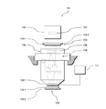
下記の図1〜図6を参照して、本発明による光学モジュールの好適な実施形態を使用した、本発明によるマイクロリソグラフィー用の光学結像装置の好適な実施形態を説明する。この場合、下記の説明を単純化するために、XYZ座標系を導入し、Z方向は垂直方向を示す。しかしながら、本発明の他の変形では、結像装置の構成要素の他のどんな空間的配列も提供できることは、自明である。
下記では、図7(図5と同様の図を示す)を参照して、本発明による光学モジュール209の好適な実施形態を利用した、本発明による結像装置201のさらに好適な実施形態を説明する。その構造および機能性において、結像装置201は基本的には結像装置101に対応し、よってここでは違いのみをカバーする。特に、同様の構成要素には同じ参照番号に100を加えたものを付し、同一の構成要素には同一の参照番号を付す。下記に記載のない限り、これらの同様の構成要素の特性に関しては、第1実施形態に関する上述の説明を明示的に参照する。
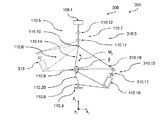
下記では、図8(図5と同様の図を示す)を参照して、本発明による光学モジュール309の好適な実施形態を利用した、本発明による結像装置301のさらに好適な実施形態を説明する。その構造および機能性において、結像装置301は、基本的には結像装置101に対応し、よってここでは違いのみをカバーする。特に、同様の構成要素には同じ参照番号に200を加えたものを付し、同一の構成要素には同一の参照番号を付す。下記に記載のない限り、これらの同様の構成要素の特性に関しては、第1実施形態に関する上述の説明を明示的に参照する。
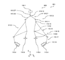
下記に、図9を参照して、本発明による光学モジュール409の好適な実施形態を利用した、本発明による結像装置401のさらに好適な実施形態を説明する。その構造および機能性において、結像装置401は基本的には結像装置101に対応し、よってここでは違いのみをカバーする。特に、同様の構成要素には同じ参照番号に300を加えたものを付し、同一の構成要素には同一の参照番号を付す。下記に記載のない限り、これらの同様の構成要素の特性に関しては、第1実施形態に関する上述の説明を明示的に参照する。
下記に、図10(図9と同様の視点からの図を示す)を参照して、本発明による光学モジュール509の好適な実施形態を利用した、本発明による結像装置501のさらに好適な実施形態を説明する。その構造および機能性において、結像装置501は基本的に結像装置401に対応し、よってここでは違いのみをカバーする。特に、同様の構成要素には同じ参照番号に100を加えたものを付し、同一の構成要素には同一の参照番号を付す。下記に記載のない限り、これらの同様の構成要素の特性に関しては、第4および第5実施形態に関する上述の説明を明示的に参照する。
下記に、図11および図12を参照して、本発明による光学モジュール609の好適な実施形態を利用した、本発明による結像装置601のさらに好適な実施形態を説明する。その構造および機能性において、結像装置601は基本的に結像装置101に対応し、よって、ここでは違いのみをカバーする。特に、同様の構成要素には同じ参照番号に500を加えたものを付し、同一の構成要素には同一の参照番号を付す。下記に記載のない限り、これらの同様の構成要素の特性に関しては、第1実施形態に関する上述の説明を明示的に参照する。
Claims (14)
- 特にマイクロリソグラフィー用の光学モジュールであって、
光学素子、および
支持ユニットを有し、
前記光学素子は、回転対称軸を画定する、少なくとも1つの光学的に利用される領域を有し、
該光学素子を支持するために、前記支持ユニットは3つ以上の支持素子を有し、
該支持素子の各々は、前記光学素子を支持方向に支持し、該支持方向における該支持素子の両端に第1端部と第2端部とを有し、前記第1端部の領域で、前記光学素子と結合され、前記第2端部の領域で、支持構造体と結合され、
少なくとも1つの支持素子は、正確に1つの第1自由度を制限し、
該第1自由度は、回転軸の周りの回転の自由度であって、
該回転軸は、該回転軸が、前記光学的に利用される領域の前記回転対称軸に平行な方向成分を有する方向に配列されることを特徴とする、光学モジュール。 - 前記少なくとも1つの支持素子は、複数のピボット接合部を有する少なくとも1つの接合群を備え、
該接合群の各ピボット接合部は、ピボット軸を画定し、
該ピボット接合部の該ピボット軸は、相互に平行に延びることを特徴とする、請求項1に記載の光学モジュール。 - 前記ピボット接合部の前記ピボット軸は、前記回転軸を横切る方向に延びることを特徴とする、請求項2に記載の光学モジュール。
- 前記接合群は、3つのピボット接合部を備えることを特徴とする、請求項2または3に記載の光学モジュール。
- 前記接合群は、第1ピボット接合部を有する第1接合群であって、それぞれ第1ピボット軸を画定し、
前記少なくとも1つの支持素子は、複数の第2ピボット接合部、特に2つの第2ピボット接合部を有する第2接合群を備え、
前記接合群の各々の第2ピボット接合部は、第2ピボット軸を画定し、
該第2ピボット軸は、相互に平行に延び、
第1ピボット軸と第2ピボット軸は相互に横切る方向に延び、
前記第1ピボット接合部は、前記支持素子に支持力が働く方向に、相互に隣接して配置され、および/または
前記第2ピボット接合部は、前記支持素子に支持力が働く方向に、相互に隣接して配置されることを特徴とする、請求項2〜4の何れかに記載の光学モジュール。 - 前記少なくとも1つの支持素子は、支持セグメントを有し、これは、該支持素子に支持力が働く方向に、前記少なくとも1つの接合群の2つのピボット接合部の間に配置され、
前記光学素子の位置および/または配向を調整するアクチュエータユニットが、前記支持セグメントに係合することを特徴とする、請求項2〜5の何れかに記載の光学モジュール。 - 前記アクチュエータユニットは、該アクチュエータユニットの動作方向における該アクチュエータユニットの両端に第1端部および第2端部を有し、
該アクチュエータユニットは、その第1端部の領域で前記支持素子に係合し、
該アクチュエータユニットは、その第2端部の領域で前記支持構造体に係合し、または、
該アクチュエータユニットは、その第2端部の領域で、支持力が働く方向に、前記支持セグメントに隣接する前記支持素子のさらなる支持セグメントに係合することを特徴とする、請求項6に記載の光学モジュール。 - 前記アクチュエータユニットは、アクチュエータおよびレバーアームを備え、
該レバーアームは前記支持セグメントに剛結合され、
前記支持セグメントを、前記ピボット接合部の前記ピボット軸に平行な軸の周りに旋回させる前記アクチュエータは、前記レバーアームに係合することを特徴とする、請求項6または7に記載の光学モジュール。 - 前記支持ユニットは、正確に5つの支持素子を有することで五脚の形態に設計されることを特徴とする、請求項1〜8の何れかに記載の光学モジュール。
- 前記支持素子のうちの少なくとも2つは、二脚を形成するように配置されることを特徴とする、請求項1〜9の何れかに記載の光学モジュール。
- 前記二脚の支持素子は、それぞれ複数のピボット接合部を備え、
2つのピボット接合部の間の前記支持素子に支持力が働く方向に、それぞれ1つの支持セグメントが配置され、
少なくとも1つの支持セグメントが、前記2つの支持素子の共通セグメントとして設計されることを特徴とする、請求項10に記載の光学モジュール。 - 特にマイクロリソグラフィー用の光学結像装置であって、
第1光学素子群を有する照明装置;
投影パターンを有するマスクを受けるマスク装置;
第2光学素子群を有する投影装置;および
基板を受ける基板装置を備え、
前記照明装置は前記投影パターンを照明するように設計され、
前記投影装置は、前記投影パターンを前記基板上に投影するように設計され、
前記照明装置および/または前記投影装置は、請求項1〜11の内の1つによる光学モジュールを備えることを特徴とする、光学結像装置。 - 特にマイクロリソグラフィー用の光学素子を支持する方法であって、
少なくとも1つの光学的に利用される領域を有し、回転対称軸を画定する該光学素子は、支持ユニットの3つ以上の支持素子によって、支持構造体上に支持され、
少なくとも1つの支持素子によって、正確に1つの第1自由度が制限され、
該第1自由度は、回転軸の周りの回転の自由度であって、
該回転軸は、該軸が前記光学的に利用される領域の前記回転対称軸に平行な方向成分を持つ方向に配列されることを特徴とする、方法。 - 特にマイクロリソグラフィー用の光学モジュールであって、
光学素子、および
支持ユニットを有し、
前記光学素子は、回転対称軸を画定する少なくとも1つの光学的に利用される領域を持ち、
前記光学素子を支持するために、前記支持ユニットは3つ以上の支持素子を有し、
該支持素子の各々は、第1端部と第2端部とを有し、かつ、前記第1端部の領域で、該光学素子と結合され、前記第2端部の領域で、支持構造体と結合され、
前記支持ユニットは、前記回転対称軸の周りの前記光学素子の回転の自由度が制限されるように設計され、該光学素子の位置または配向は、他の5つの自由度では、該支持ユニットを介して空間的に調整可能であることを特徴とする、光学モジュール。
Applications Claiming Priority (2)
| Application Number | Priority Date | Filing Date | Title |
|---|---|---|---|
| DE102010018224.9 | 2010-04-23 | ||
| DE102010018224A DE102010018224A1 (de) | 2010-04-23 | 2010-04-23 | Optisches Modul mit einem verstellbaren optischen Element |
Publications (3)
| Publication Number | Publication Date |
|---|---|
| JP2011232751A JP2011232751A (ja) | 2011-11-17 |
| JP2011232751A5 JP2011232751A5 (ja) | 2014-06-05 |
| JP6008468B2 true JP6008468B2 (ja) | 2016-10-19 |
Family
ID=44815562
Family Applications (1)
| Application Number | Title | Priority Date | Filing Date |
|---|---|---|---|
| JP2011096245A Active JP6008468B2 (ja) | 2010-04-23 | 2011-04-22 | 調整可能な光学素子を有する光学モジュール |
Country Status (4)
| Country | Link |
|---|---|
| US (1) | US10274845B2 (ja) |
| JP (1) | JP6008468B2 (ja) |
| KR (1) | KR101808860B1 (ja) |
| DE (1) | DE102010018224A1 (ja) |
Families Citing this family (2)
| Publication number | Priority date | Publication date | Assignee | Title |
|---|---|---|---|---|
| US9254538B2 (en) | 2013-04-16 | 2016-02-09 | Corning Incorporated | Method of minimizing stacking element distortions in optical assemblies |
| DE102019218609A1 (de) * | 2019-11-29 | 2021-06-02 | Carl Zeiss Smt Gmbh | Abstützung einer optischen einheit |
Family Cites Families (11)
| Publication number | Priority date | Publication date | Assignee | Title |
|---|---|---|---|---|
| JP2000066075A (ja) | 1998-08-17 | 2000-03-03 | Nikon Corp | 光学系及びその製造方法、並びに前記光学系を備えた露光装置 |
| JP2002083766A (ja) | 2000-06-19 | 2002-03-22 | Nikon Corp | 投影光学系、該光学系の製造方法、及び前記光学系を備えた投影露光装置 |
| AU2001277758A1 (en) | 2000-08-18 | 2002-03-04 | Nikon Corporation | Optical element holding device |
| DE10115914A1 (de) * | 2001-03-30 | 2002-10-02 | Zeiss Carl | Vorrichtung zur Lagerung eines optischen Elementes in einer Optik |
| DE10344178B4 (de) * | 2003-09-24 | 2006-08-10 | Carl Zeiss Smt Ag | Halte- und Positioniervorrichtung für ein optisches Element |
| US7515359B2 (en) * | 2004-04-14 | 2009-04-07 | Carl Zeiss Smt Ag | Support device for positioning an optical element |
| JP2008111891A (ja) | 2006-10-30 | 2008-05-15 | Canon Inc | 光学要素の保持装置及びそれを備えた露光装置 |
| KR20080038050A (ko) * | 2006-10-27 | 2008-05-02 | 캐논 가부시끼가이샤 | 광학 요소 유지장치 및 노광 장치 |
| EP1995534A1 (de) * | 2007-05-19 | 2008-11-26 | Fritz Brinkmann | Steuerung und Antrieb eines kippbaren Solarreflektors zur Leistungssteigerung und zum Schutz von flächigen Sonnenkollektoren |
| DE102009044957A1 (de) * | 2008-09-30 | 2010-04-08 | Carl Zeiss Smt Ag | Stützelemente für ein optisches Element |
| US9664982B2 (en) * | 2015-03-12 | 2017-05-30 | Panasonic Intellectual Property Management Co., Ltd. | Optical system driving device, lens barrel, and optical device |
-
2010
- 2010-04-23 DE DE102010018224A patent/DE102010018224A1/de not_active Ceased
-
2011
- 2011-04-21 US US13/091,457 patent/US10274845B2/en active Active
- 2011-04-22 JP JP2011096245A patent/JP6008468B2/ja active Active
- 2011-04-22 KR KR1020110037620A patent/KR101808860B1/ko active IP Right Grant
Also Published As
| Publication number | Publication date |
|---|---|
| US10274845B2 (en) | 2019-04-30 |
| KR101808860B1 (ko) | 2017-12-13 |
| JP2011232751A (ja) | 2011-11-17 |
| US20110261341A1 (en) | 2011-10-27 |
| DE102010018224A1 (de) | 2012-02-16 |
| KR20110118579A (ko) | 2011-10-31 |
Similar Documents
| Publication | Publication Date | Title |
|---|---|---|
| KR101332471B1 (ko) | 대물 렌즈, 특히 반도체 리소그래피용 투사 대물 렌즈 | |
| US9213245B2 (en) | Optical system and multi facet mirror of a microlithographic projection exposure apparatus | |
| US9110388B2 (en) | Projection exposure apparatus with multiple sets of piezoelectric elements moveable in different directions and related method | |
| US7242537B2 (en) | Holding and positioning apparatus for an optical element | |
| CN107077076B (zh) | 微光刻投射曝光装置的光学配置 | |
| US8553202B2 (en) | Projection objective for microlithography | |
| JP2013511843A5 (ja) | ||
| JP5128665B2 (ja) | 寄生負荷最小化光学素子モジュール | |
| WO2008122313A1 (en) | Optical element module with imaging error and position correction | |
| KR20060123509A (ko) | 마이크로리소그래픽 투사 노출 시스템의 투사 렌즈 | |
| US20240159988A1 (en) | Support for an optical element | |
| JP6008468B2 (ja) | 調整可能な光学素子を有する光学モジュール | |
| US9645388B2 (en) | Facet mirror device | |
| JP5127515B2 (ja) | 光学素子保持装置 | |
| TW200947163A (en) | Positioning unit of optical element, optical system, exposure apparatus, adjustment method of optical system | |
| JP6352953B2 (ja) | 光学系の少なくとも1つの素子を作動させる構成体 | |
| KR20140123047A (ko) | 특히 마이크로리소그래피 투영 노광 장치에 사용하기 위한 미러 장치 | |
| KR102694720B1 (ko) | 특히 마이크로리소그래픽 투영 노광 장치용 광학 시스템 | |
| JP5848470B2 (ja) | 寄生負荷最小化光学素子モジュール | |
| JP6240142B2 (ja) | 寄生負荷最小化光学素子モジュール | |
| KR20240055798A (ko) | 변형 가능 렌즈 플레이트를 사용한 배율 조정 가능 투사 시스템 | |
| TW202405507A (zh) | 用於微鏡面陣列之鏡面總成 | |
| JP5695011B2 (ja) | 寄生負荷最小化光学素子モジュール |
Legal Events
| Date | Code | Title | Description |
|---|---|---|---|
| A521 | Request for written amendment filed |
Free format text: JAPANESE INTERMEDIATE CODE: A523 Effective date: 20140421 |
|
| A621 | Written request for application examination |
Free format text: JAPANESE INTERMEDIATE CODE: A621 Effective date: 20140421 |
|
| A977 | Report on retrieval |
Free format text: JAPANESE INTERMEDIATE CODE: A971007 Effective date: 20141226 |
|
| A131 | Notification of reasons for refusal |
Free format text: JAPANESE INTERMEDIATE CODE: A131 Effective date: 20150127 |
|
| A601 | Written request for extension of time |
Free format text: JAPANESE INTERMEDIATE CODE: A601 Effective date: 20150427 |
|
| A601 | Written request for extension of time |
Free format text: JAPANESE INTERMEDIATE CODE: A601 Effective date: 20150526 |
|
| A601 | Written request for extension of time |
Free format text: JAPANESE INTERMEDIATE CODE: A601 Effective date: 20150626 |
|
| A521 | Request for written amendment filed |
Free format text: JAPANESE INTERMEDIATE CODE: A523 Effective date: 20150724 |
|
| A131 | Notification of reasons for refusal |
Free format text: JAPANESE INTERMEDIATE CODE: A131 Effective date: 20160105 |
|
| A601 | Written request for extension of time |
Free format text: JAPANESE INTERMEDIATE CODE: A601 Effective date: 20160315 |
|
| A521 | Request for written amendment filed |
Free format text: JAPANESE INTERMEDIATE CODE: A523 Effective date: 20160628 |
|
| TRDD | Decision of grant or rejection written | ||
| A01 | Written decision to grant a patent or to grant a registration (utility model) |
Free format text: JAPANESE INTERMEDIATE CODE: A01 Effective date: 20160816 |
|
| A61 | First payment of annual fees (during grant procedure) |
Free format text: JAPANESE INTERMEDIATE CODE: A61 Effective date: 20160913 |
|
| R150 | Certificate of patent or registration of utility model |
Ref document number: 6008468 Country of ref document: JP Free format text: JAPANESE INTERMEDIATE CODE: R150 |
|
| R250 | Receipt of annual fees |
Free format text: JAPANESE INTERMEDIATE CODE: R250 |
|
| R250 | Receipt of annual fees |
Free format text: JAPANESE INTERMEDIATE CODE: R250 |
|
| R250 | Receipt of annual fees |
Free format text: JAPANESE INTERMEDIATE CODE: R250 |
|
| R250 | Receipt of annual fees |
Free format text: JAPANESE INTERMEDIATE CODE: R250 |
|
| R250 | Receipt of annual fees |
Free format text: JAPANESE INTERMEDIATE CODE: R250 |
|
| R250 | Receipt of annual fees |
Free format text: JAPANESE INTERMEDIATE CODE: R250 |


