WO2016017413A1 - 蓄電装置 - Google Patents
蓄電装置 Download PDFInfo
- Publication number
- WO2016017413A1 WO2016017413A1 PCT/JP2015/070076 JP2015070076W WO2016017413A1 WO 2016017413 A1 WO2016017413 A1 WO 2016017413A1 JP 2015070076 W JP2015070076 W JP 2015070076W WO 2016017413 A1 WO2016017413 A1 WO 2016017413A1
- Authority
- WO
- WIPO (PCT)
- Prior art keywords
- jig
- electrode terminal
- storage device
- case
- column portion
- Prior art date
- Legal status (The legal status is an assumption and is not a legal conclusion. Google has not performed a legal analysis and makes no representation as to the accuracy of the status listed.)
- Ceased
Links
Images



Classifications
-
- H—ELECTRICITY
- H01—ELECTRIC ELEMENTS
- H01M—PROCESSES OR MEANS, e.g. BATTERIES, FOR THE DIRECT CONVERSION OF CHEMICAL ENERGY INTO ELECTRICAL ENERGY
- H01M50/00—Constructional details or processes of manufacture of the non-active parts of electrochemical cells other than fuel cells, e.g. hybrid cells
- H01M50/50—Current conducting connections for cells or batteries
- H01M50/543—Terminals
- H01M50/564—Terminals characterised by their manufacturing process
- H01M50/567—Terminals characterised by their manufacturing process by fixing means, e.g. screws, rivets or bolts
-
- H—ELECTRICITY
- H01—ELECTRIC ELEMENTS
- H01G—CAPACITORS; CAPACITORS, RECTIFIERS, DETECTORS, SWITCHING DEVICES, LIGHT-SENSITIVE OR TEMPERATURE-SENSITIVE DEVICES OF THE ELECTROLYTIC TYPE
- H01G11/00—Hybrid capacitors, i.e. capacitors having different positive and negative electrodes; Electric double-layer [EDL] capacitors; Processes for the manufacture thereof or of parts thereof
- H01G11/74—Terminals, e.g. extensions of current collectors
-
- H—ELECTRICITY
- H01—ELECTRIC ELEMENTS
- H01M—PROCESSES OR MEANS, e.g. BATTERIES, FOR THE DIRECT CONVERSION OF CHEMICAL ENERGY INTO ELECTRICAL ENERGY
- H01M50/00—Constructional details or processes of manufacture of the non-active parts of electrochemical cells other than fuel cells, e.g. hybrid cells
- H01M50/10—Primary casings; Jackets or wrappings
- H01M50/172—Arrangements of electric connectors penetrating the casing
- H01M50/174—Arrangements of electric connectors penetrating the casing adapted for the shape of the cells
- H01M50/176—Arrangements of electric connectors penetrating the casing adapted for the shape of the cells for prismatic or rectangular cells
-
- H—ELECTRICITY
- H01—ELECTRIC ELEMENTS
- H01M—PROCESSES OR MEANS, e.g. BATTERIES, FOR THE DIRECT CONVERSION OF CHEMICAL ENERGY INTO ELECTRICAL ENERGY
- H01M50/00—Constructional details or processes of manufacture of the non-active parts of electrochemical cells other than fuel cells, e.g. hybrid cells
- H01M50/50—Current conducting connections for cells or batteries
- H01M50/543—Terminals
- H01M50/547—Terminals characterised by the disposition of the terminals on the cells
- H01M50/55—Terminals characterised by the disposition of the terminals on the cells on the same side of the cell
-
- H—ELECTRICITY
- H01—ELECTRIC ELEMENTS
- H01M—PROCESSES OR MEANS, e.g. BATTERIES, FOR THE DIRECT CONVERSION OF CHEMICAL ENERGY INTO ELECTRICAL ENERGY
- H01M50/00—Constructional details or processes of manufacture of the non-active parts of electrochemical cells other than fuel cells, e.g. hybrid cells
- H01M50/50—Current conducting connections for cells or batteries
- H01M50/543—Terminals
- H01M50/552—Terminals characterised by their shape
- H01M50/553—Terminals adapted for prismatic, pouch or rectangular cells
-
- Y—GENERAL TAGGING OF NEW TECHNOLOGICAL DEVELOPMENTS; GENERAL TAGGING OF CROSS-SECTIONAL TECHNOLOGIES SPANNING OVER SEVERAL SECTIONS OF THE IPC; TECHNICAL SUBJECTS COVERED BY FORMER USPC CROSS-REFERENCE ART COLLECTIONS [XRACs] AND DIGESTS
- Y02—TECHNOLOGIES OR APPLICATIONS FOR MITIGATION OR ADAPTATION AGAINST CLIMATE CHANGE
- Y02E—REDUCTION OF GREENHOUSE GAS [GHG] EMISSIONS, RELATED TO ENERGY GENERATION, TRANSMISSION OR DISTRIBUTION
- Y02E60/00—Enabling technologies; Technologies with a potential or indirect contribution to GHG emissions mitigation
- Y02E60/10—Energy storage using batteries
Definitions
- the present invention relates to a power storage device in which an electrode terminal is fastened to a wall portion by a nut screwed into a male screw portion of a pole column portion.
- a secondary battery (power storage device) having a large capacity includes a case, and an electrode assembly and an electrolytic solution are accommodated in the case. Electrode terminals for transmitting and receiving electricity to and from the electrode assembly are connected to the electrode assembly through conductive members. In addition, the electrode terminal has a pole portion that penetrates the lid of the case and projects out of the case. The pole column portion has a male screw portion on the outer peripheral surface. In such a structure, the electrode terminal connected to the electrode assembly is fastened to the lid by screwing a nut into the male screw portion.
- the secondary battery is used by connecting an external conducting member (for example, a bus bar) to the tip end surface of the pole portion of the electrode terminal.
- an external conducting member for example, a bus bar
- a recess having an inner peripheral surface is provided in the pole column portion, a female screw portion is formed on the inner peripheral surface, and a fixing member such as a bolt is attached to the female screw portion.
- a fixing member such as a bolt is attached to the female screw portion.
- the external conducting member is formed by a plate-like member having an insertion portion, and the conducting member is sandwiched between the tip surface of the pole column portion and the fixing member.
- the electrode terminal is prevented from rotating by engaging a jig with the tip surface of the pole column part
- the nut is screwed
- An object of the present invention is to provide a power storage device that can suppress a protruding portion from being formed on the tip surface of a pole column portion when a nut is screwed together.
- a power storage device for achieving the above object includes a case having a wall portion, an electrode assembly housed in the case, and an electrode terminal that exchanges electricity with the electrode assembly.
- the electrode terminal includes a pole column portion protruding from the wall portion of the case, and a male screw portion provided on an outer peripheral surface of the pole column portion.
- the electrode terminal is fastened to the wall portion by a nut screwed into the male screw portion.
- the polar column portion has a tip surface located in a protruding direction of the polar column portion.
- the electrode terminal has a jig recess provided on the distal end surface.
- the jig recess has a shape other than a perfect circle in plan view, and the jig recess has an engaging portion that can be engaged with a jig inserted into the jig recess.
- the pole column portion has a deformation absorbing portion that is recessed from the tip surface at the opening edge of the jig recess on the tip surface.
- the partial top view which shows a pole part, the recessed part for jig
- the perspective view which shows the state which inserts a jig
- (A) is a fragmentary sectional view which shows the state which inserted the jig
- (B) is the elements on larger scale of (A). Sectional drawing which expands and shows an electrode terminal and a conduction member.
- the battery module 10 includes a plurality of secondary batteries 20, and the secondary battery 20 is a lithium ion secondary battery having an external appearance. Adjacent secondary batteries 20 are connected by a bus bar 11.
- the bus bar 11 is a rectangular metal plate, and has insertion holes 11a on both sides in the longitudinal direction.
- the bus bar 11 is fixed to the secondary battery 20 by a fixing member 12 inserted through the insertion hole 11a.
- the fixing member 12 has a bolt shape, and includes a shaft portion 12a having an external thread on the outer peripheral surface, and a disk-shaped head portion 12b having a larger diameter than the shaft portion 12a.
- the secondary battery 20 as the power storage device includes a case 21 that forms the outer shape of the secondary battery 20.
- the case 21 includes a rectangular cylindrical case main body 22 and a rectangular flat plate-like lid body 23 that closes the opening of the case main body 22.
- the secondary battery 20 includes an electrode assembly 24 housed in a case 21 and two electrode terminals 31 that exchange electricity with the electrode assembly 24.
- the two electrode terminals 31 are arranged at an interval in the longitudinal direction of the lid body 23.
- the two electrode terminals 31 include a positive terminal and a negative terminal.
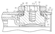
- the electrode terminal 31 has a plate-like base 32. From the center of the base 32, a cylindrical pole column 33 is erected. The pole portion 33 and the base portion 32 are integral and are both made of copper. The pole portion 33 has a male screw portion 34 on the outer peripheral surface.
- the base portion 32 is located in the case 21, and the pole column portion 33 protrudes from the base portion 32 toward the outside of the case 21. Specifically, the pole portion 33 protrudes outside the case 21 through the through hole 25 provided in the lid body 23 as a wall portion.
- the electrode terminal 31 is fastened to the case 21 by screwing the nut 35 into the pole portion 33 protruding outside the case 21.
- a cylindrical insulating member 27 is provided between the inner peripheral surface of the through hole 25 and the outer peripheral surface of the pole column portion 33.
- a rubber seal member 29 is interposed between the facing surfaces of the lid body 23 and the base portion 32 so as to surround the through hole 25.
- the through hole 25 is sealed by the seal member 29.
- a resin-made and cylindrical terminal cover 50 is attached to the base 32 of the electrode terminal 31, and the electrode terminal 31 is insulated from the lid body 23.
- the base 32 is defined as the base end and the side opposite to the base 32 is defined as the tip in the protruding direction of the polar column portion 33 from the lid body 23.
- the pole portion 33 has a jig recess 37 that opens to the distal end surface 36 in the protruding direction.
- the jig recess 37 is recessed from the distal end surface 36 toward the base 32.
- the jig concave portion 37 has a shape other than a perfect circle in a plan view as viewed from the protruding direction of the pole column portion 33.
- the planar shape of the jig recess 37 is a hexagonal shape.
- the jig concave portion 37 is recessed in a hexagonal shape from the distal end surface 36 toward the proximal end of the pole column portion 33. And the recessed part 37 for jig
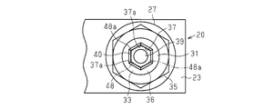
- the jig concave portion 37 has six engaging portions 37a at regular intervals.
- a jig 48 made of metal can be engaged with the jig recess 37.
- the jig 48 is a rod having a hexagonal cross section over the entire axial direction.
- the jig 48 has an engaging protrusion 48a at a corner formed by the adjacent side surfaces intersecting each other.
- the jig 48 has six engaging protrusions 48a at regular intervals.
- the jig 48 when the jig 48 is inserted into the jig concave portion 37, the six engaging portions 37 a of the jig concave portion 37 and the six engaging protrusions 48 a of the jig 48 are formed. Engagement is possible, and an engagement point is formed.
- the jig 48 has a length that protrudes from the tip surface 36 in a state where the engaging protrusion 48 a is engaged with the engaging portion 37 a of the jig recess 37.
- the electrode terminal 31 has a female screw part 39 behind the jig recess 37.
- the shaft portion 12 a of the fixing member 12 can be screwed into the female screw portion 39.
- the dimension (area) in plan view of the female thread portion 39 is smaller than the dimension (area) in plan view of the jig recess 37.
- the shaft portion 12 a of the fixing member 12 can be screwed into the female screw portion 39 through the jig recess 37.
- the pole portion 33 has a deformation absorbing portion 40 along the opening edge of the distal end surface 36 of the jig recess 37.
- the deformation absorbing portion 40 has a hexagonal shape in plan view that matches the shape of the concave portion 37 for jig, and is provided over the entire opening edge of the concave portion 37 for jig.
- transformation absorption part 40 exists in the position near the front end surface 36 rather than the engaging part 37a in the protrusion direction of the pole part 33.
- FIG. Further, the deformation absorbing portion 40 is provided along the opening edge of the jig concave portion 37 at a portion recessed from the distal end surface 36 of the pole column portion 33.
- the deformation absorbing portion 40 In the cross section along the protruding direction of the polar column portion 33, the deformation absorbing portion 40 is inclined downward toward the central axis of the polar column portion 33 as it goes from the distal end surface 36 to the proximal end. Therefore, the deformation absorbing portion 40 has a tapered shape whose diameter increases from the proximal end to the distal end of the polar column portion 33 along the protruding direction of the polar column portion 33.
- the deformation absorbing portion 40 is located in the gap S (region) formed by being recessed from the distal end surface 36 of the polar column portion 33.
- a pair of electrode terminals 31 are connected to the electrode assembly 24 by welding.
- the lid body 23 With the sealing member 29 and the terminal cover 50 mounted on the base portion 32 of the electrode terminal 31, the lid body 23 is placed on the terminal cover 50, and the pole column portion 33 of each electrode terminal 31 is inserted into each through hole 25.
- an insulating member 27 is interposed between the inner peripheral surface of the through hole 25 and the pole column portion 33. Then, as shown in FIG. 5, the electrode assembly 24, the electrode terminal 31, the seal member 29, the terminal cover 50, the insulating member 27, and the lid body 23 are integrated.
- the jig concave portion 37 and the deformation absorbing portion 40 of the electrode terminal 31 are directed upward.
- a deformed portion 33 a is formed in the polar column portion 33 that is deformed so that the polar column portion 33 rises toward the tip surface 36.
- the deformation of the polar column portion 33 occurs as a deformation of the deformation absorbing portion 40 in the gap S, and the deformation of the polar column portion 33 is absorbed by the deformation absorbing portion 40.
- the deformation absorbing part 40 is set to be larger than the volume of the deformation part 33a.
- each electrode terminal 31 is fastened to the lid body 23.
- the electrode assembly 24 is accommodated in the case body 22, the lid body 23 is joined to the case body 22, and the case 21 is formed.
- the battery 20 is assembled.
- the shaft portion 12 a of the fixing member 12 is inserted into the insertion hole 11 a of the bus bar 11, and the shaft portion 12 a is connected to each electrode terminal 31. Screwed into the female screw portion 39. And the bus-bar 11 is pressed toward the front end surface 36 of each polar-column part 33 by the head 12b. As a result, the portion of the bus bar 11 positioned around the insertion hole 11 a, that is, the portion in contact with the distal end surface 36 is pressed against each distal end surface 36. Then, the different rechargeable batteries 20 are electrically connected by the bus bar 11 with the electrode terminals 31 having different polarities.
- the deformation absorbing portion 40 is formed at a position recessed from the tip surface 36 along the opening edge of the jig recess 37. For this reason, even if the pole column 33 is deformed when the nut 35 is screwed in a state where the electrode terminal 31 is prevented from rotating by the jig 48, the deformation is absorbed in the region recessed from the distal end surface 36. It occurs as a deformation of the part 40. For this reason, even if the polar column portion 33 is deformed, the protruding portion is prevented from being formed on the distal end surface 36. As a result, when the bus bar 11 is fixed to the electrode terminal 31, the bus bar 11 does not run on the protruding portion, and the bus bar 11 can be brought into contact with the entire front end surface 36. The contact area is not reduced.
- the deformation absorbing portion 40 is provided over the entire opening edge of the jig recess 37. Therefore, even if a deformation occurs in any place on the inner surface of the jig recess 37, the deformation is absorbed as a deformation in the deformation absorbing portion 40, and a protruding portion is not formed on the distal end surface 36.
- the deformation absorbing portion 40 has a shape that expands in diameter from the proximal end toward the distal end along the protruding direction of the polar column portion 33. For this reason, it becomes easy to insert the shaft portion 12 a when inserting the jig 48 into the concave portion 37 for jig or screwing the fixing member 12 into the female screw portion 39.
- the deformation absorbing portion 40 has a tapered shape that increases in diameter as it goes from the proximal end to the distal end along the protruding direction of the polar column portion 33.
- the engaging protrusion 48a of the jig 48 and the engaging portion of the jig recess 37 are used. A wide area of engagement with 37a can be secured, and accompanying rotation of the electrode terminal 31 can be suppressed.
- the above embodiment may be modified as follows.
- the deformation absorbing portion 40 is not provided over the entire opening edge of the jig recess 37, and may be provided, for example, at an opening edge corresponding to one engaging portion 37a, or a plurality of engagements. You may be provided in the opening edge corresponding to the part 37a. Further, the deformation absorbing portion 40 may be provided along half of the opening edge of the jig recess 37. That is, the position where the deformation absorbing portion 40 is provided may be changed as appropriate.
- the planar view shape of the jig recess 37 may not be a hexagonal shape, but may be an arbitrary polygonal shape such as a triangular shape, a quadrangular shape, a pentagonal shape, or the like. Further, the planar shape of the jig concave portion 37 may be an elliptical shape or an arbitrary rounded shape such as an oval track shape. In short, the shape of the jig recess 37 in plan view may be arbitrarily changed as long as the jig can be engaged with the jig recess 37 and the electrode terminal 31 can be prevented from rotating.
- the deformation absorbing portion 40 does not have to have a tapered shape in which the diameter increases as it goes from the proximal end to the distal end along the protruding direction of the polar column portion 33.
- the deformation absorbing portion 40 has a shape that can absorb the deformation of the polar column portion 33 in the recess. If there is, the shape may be changed as appropriate.
- the bus bar 11 is connected to the electrode terminal 31 by screwing the fixing member 12 to the female screw portion 39, but is not limited thereto.
- the bus bar 11 may be connected to the electrode terminal 31 by welding the bus bar 11 to the distal end surface 36 of the electrode terminal 31.
- the electrode terminal 31 has a female screw part 39 for connecting the bus bar 11, but the female screw part 39 may be omitted.
- the wall portion is embodied in the lid body 23 of the case 21, but the wall portion may be a side wall of the case main body 22.
- a member connected to the tip surface 36 of the electrode terminal 31 is not limited to the bus bar 11 that connects the secondary batteries 20 to form the battery module 10.
- a member that connects the secondary battery 20 and an external device may be used. In this case, the same effect can be obtained.
- the secondary battery 20 is a lithium ion secondary battery, but is not limited thereto, and may be another type of secondary battery.
- the present invention may be embodied in any power storage device such as an electric double layer capacitor.
Landscapes
- Chemical & Material Sciences (AREA)
- Chemical Kinetics & Catalysis (AREA)
- Electrochemistry (AREA)
- General Chemical & Material Sciences (AREA)
- Engineering & Computer Science (AREA)
- Manufacturing & Machinery (AREA)
- Power Engineering (AREA)
- Microelectronics & Electronic Packaging (AREA)
- Connection Of Batteries Or Terminals (AREA)
- Electric Double-Layer Capacitors Or The Like (AREA)
- Sealing Battery Cases Or Jackets (AREA)
Abstract
蓄電装置は、ケース及び電極端子を備える。電極端子は、ケースの壁部から突出した極柱部と、該極柱部の外周面に設けられた雄ねじ部とを有する。電極端子は、極柱部の先端面に設けられた治具用凹部を有する。治具用凹部の平面視形状は、真円以外の形状である。治具用凹部は、治具用凹部に挿入された治具に係合可能な係合部を有する。極柱部は、先端面での治具用凹部の開口縁に、先端面より凹んだ変形吸収部を有する。
Description
本発明は、極柱部の雄ねじ部に螺合されたナットにより電極端子が壁部に締結されている蓄電装置に関する。
二次電池やキャパシタのような蓄電装置は再充電可能であり、繰り返し使用することができるため電源として広く利用されている。一般に、容量の大きな二次電池(蓄電装置)はケースを備え、そのケース内に電極組立体及び電解液が収容されている。電極組立体と電気を授受するための電極端子が、導電部材を介して電極組立体に接続されている。また、電極端子は、ケースの蓋を貫通して、ケース外に突出する極柱部を有する。この極柱部は外周面に雄ねじ部を備える。そして、このような構造にて、電極組立体に接続された電極端子は、雄ねじ部にナットを螺合することで蓋に締結されている。
電極端子にナットを螺合する際、ナットと共に電極端子が連れ回りすると、電極端子に一体の導電部材がケースに接触して短絡の原因になる虞がある。そこで、ナットを螺合する際に電極端子の連れ回りを抑制するために、例えば、特許文献1に開示の技術を採用することが考えられる。具体的には、電極端子において、極柱部の先端面に治具が係合可能な凹部が形成される。その凹部に治具を係合させ、かつ治具を回転不能にした状態で、電極端子の雄ねじ部にナットが螺合される。
二次電池は、電極端子における極柱部の先端面に外部の導通部材(例えば、バスバー)を接続して使用される。この導通部材を極柱部に接続する方法として、極柱部に内周面を有する凹部を設け、その内周面に雌ねじ部を形成しておき、この雌ねじ部にボルトのような固定部材を螺合する方法がある。このとき、外部の導通部材は、挿通部を有する板状部材により形成され、この導通部材は、極柱部の先端面と固定部材とで挟持される。
しかし、極柱部の先端面に治具を係合させて電極端子の回り止めを行う構造においては、ナットを螺合する際、極柱部において治具に係合した部分には、電極端子が回転しようとする力を受け止めることに伴う応力が発生する。その応力によって極柱部の先端面が盛り上がるように突出部が形成されてしまうことがある。すると、固定部材で導通部材を極柱部に固定した際、導通部材は、極柱部の先端面ではなく、先端面から盛り上がった突出部にしか接触しない。そのため、電極端子と導通部材との接触面積が減少してしまう。
本発明の目的は、ナットを螺合する際に、極柱部の先端面に突出部が形成されることを抑制することができる蓄電装置を提供することにある。
上記目的を達成するための蓄電装置は、壁部を有するケースと、前記ケース内に収容された電極組立体と、前記電極組立体と電気を授受する電極端子とを備える。前記電極端子は、前記ケースの前記壁部から突出した極柱部と、前記極柱部の外周面に設けられた雄ねじ部とを有する。前記雄ねじ部に螺合されたナットにより前記電極端子が前記壁部に締結されている。前記極柱部は、該極柱部の突出方向に位置する先端面を有する。前記電極端子は、前記先端面に設けられた治具用凹部を有する。前記治具用凹部の平面視形状が真円以外の形状であり、前記治具用凹部は、治具用凹部に挿入された治具に係合可能な係合部を有する。前記極柱部は、前記先端面での前記治具用凹部の開口縁に、前記先端面より凹んだ変形吸収部を有する。
以下、蓄電装置を二次電池に具体化した一実施形態を図1~図7にしたがって説明する。
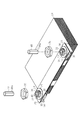
図1に示すように、電池モジュール10は複数の二次電池20を備え、二次電池20は外観が角型のリチウムイオン二次電池である。隣り合う二次電池20同士は、バスバー11によって接続されている。
図1に示すように、電池モジュール10は複数の二次電池20を備え、二次電池20は外観が角型のリチウムイオン二次電池である。隣り合う二次電池20同士は、バスバー11によって接続されている。
図1及び図7に示すように、バスバー11は、矩形板状の金属板であり、長手方向の両側に挿通孔11aを有する。また、バスバー11は、挿通孔11aに挿通された固定部材12によって二次電池20に固定されている。固定部材12は、ボルト状であり、外周面に雄ねじを有する軸部12aと、軸部12aより大径をなす円板状の頭部12bとを有する。
図2に示すように、蓄電装置としての二次電池20は、その外形を構成するケース21を備えている。ケース21は、矩形筒状のケース本体22と、ケース本体22の開口部を塞ぐ矩形平板状の蓋体23とから構成されている。二次電池20は、ケース21に収容されている電極組立体24と、電極組立体24と電気を授受する二つの電極端子31とを備えている。二つの電極端子31は、蓋体23の長手方向に間隔を空けて配置されている。二つの電極端子31は、正極端子及び負極端子を含む。
図3に示すように、電極端子31は、板状の基部32を有している。基部32の中央からは、円筒状の極柱部33が立設している。極柱部33と、基部32とは、一体であり、ともに銅製である。極柱部33は、外周面に雄ねじ部34を有している。基部32は、ケース21内に位置しており、極柱部33は、基部32からケース21外に向けて突出している。具体的にいえば、極柱部33は、壁部としての蓋体23に設けられた貫通孔25を貫通してケース21の外部に突出している。
そして、ケース21外に突出した極柱部33にナット35を螺合することで、電極端子31がケース21に締結されている。貫通孔25の内周面と極柱部33の外周面との間には、円筒状をなす絶縁部材27が設けられている。また、蓋体23と基部32の対向面同士の間には、貫通孔25を囲むようにゴム製のシール部材29が介装されている。シール部材29によって貫通孔25がシールされている。また、電極端子31の基部32には、樹脂製及び円筒状の端子カバー50が装着され、電極端子31が蓋体23から絶縁されている。
図3及び図4に示すように、極柱部33の蓋体23からの突出方向において、基部32を基端、基部32とは反対側を先端と定義する。極柱部33は、突出方向の先端面36に開口する治具用凹部37を有する。この治具用凹部37は、先端面36から基部32に向けて凹んでいる。治具用凹部37は、極柱部33の突出方向から見た平面視で真円以外の形状である。具体的には、治具用凹部37の平面視形状は六角形状である。治具用凹部37は、極柱部33の基端に向けて先端面36から六角形状に凹んでいる。そして、治具用凹部37は、6つの内側面のうち、隣り合う内側面同士が交わって形成された角部に係合部37aを有する。治具用凹部37は6つの係合部37aを等間隔おきに有する。
図5並びに図6(A)及び図6(B)に示すように、治具用凹部37には、金属製の治具48が係合可能である。治具48は、軸方向全体に亘って断面六角形の棒状である。治具48は、隣り合う側面同士が交わって形成された角部に係合突部48aを有する。治具48は6つの係合突部48aを等間隔おきに有する。
そして、図4に示すように、治具48が治具用凹部37に挿入されると、治具用凹部37の6つの係合部37aと、治具48の6つの係合突部48aが係合可能となり、係合箇所が形成されるようになっている。また、治具48は、係合突部48aを治具用凹部37の係合部37aに係合させた状態で、先端面36から突出する長さを有する。
図3に示すように、電極端子31は、治具用凹部37より奥に雌ねじ部39を有する。この雌ねじ部39には、バスバー11を電極端子31の極柱部33に接続するために、上述の固定部材12の軸部12aが螺合可能である。また、雌ねじ部39の平面視の寸法(面積)は、治具用凹部37の平面視の寸法(面積)より小さい。固定部材12の軸部12aは、治具用凹部37を貫通して雌ねじ部39に螺合可能である。
図3及び図4に示すように、極柱部33は、治具用凹部37の先端面36での開口縁に沿って変形吸収部40を有する。変形吸収部40は、治具用凹部37の平面視形状に合わせた平面視六角環状であり、治具用凹部37の開口縁全体に亘って設けられている。そして、変形吸収部40は、極柱部33の突出方向において、係合部37aよりも先端面36に近い位置にある。また、変形吸収部40は、治具用凹部37の開口縁に沿って、極柱部33の先端面36から凹んだ部分に設けられている。極柱部33の突出方向に沿った断面では、変形吸収部40は、先端面36から基端に向かうに従い、極柱部33の中心軸に向けて下り傾斜している。したがって、極柱部33の突出方向に沿って、極柱部33の基端から先端に向かうに従い、変形吸収部40は拡径したテーパ形状である。
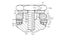
このため、治具用凹部37に治具48が挿入された状態では、図6(B)の2点鎖線に示すように、変形吸収部40と、治具48の各側面との間には隙間Sが画定される。この隙間Sは、極柱部33の突出方向に沿って基端から先端に向かう方向では徐々に広がっている。よって、変形吸収部40は、極柱部33の先端面36から凹むことで形成された隙間S(領域)内に位置していることになる。
次に、二次電池20の製造方法について作用とともに説明する。
図示しないが、電極組立体24に一対の電極端子31が溶接によって接続される。電極端子31の基部32にシール部材29及び端子カバー50が装着された状態で、端子カバー50に蓋体23が載せられて、各貫通孔25に各電極端子31の極柱部33が挿通される。さらに、貫通孔25の内周面と極柱部33との間に絶縁部材27を介装される。すると、図5に示すように、電極組立体24と、電極端子31と、シール部材29と、端子カバー50と、絶縁部材27と、蓋体23とが一体化される。
図示しないが、電極組立体24に一対の電極端子31が溶接によって接続される。電極端子31の基部32にシール部材29及び端子カバー50が装着された状態で、端子カバー50に蓋体23が載せられて、各貫通孔25に各電極端子31の極柱部33が挿通される。さらに、貫通孔25の内周面と極柱部33との間に絶縁部材27を介装される。すると、図5に示すように、電極組立体24と、電極端子31と、シール部材29と、端子カバー50と、絶縁部材27と、蓋体23とが一体化される。
次に、電極組立体24における積層方向の一面が下面となるように電極組立体24を横倒しにした状態で、電極端子31の治具用凹部37及び変形吸収部40を上方に向けられる。
図6(A)及び図6(B)に示すように、各治具用凹部37内に治具48を挿入することにより、図4の2点鎖線に示すように、治具48の係合突部48aを治具用凹部37の係合部37aに係合可能とした箇所が6箇所形成される。そして、両治具48を、図示しない工具で回り止めした状態で各極柱部33の雄ねじ部34にナット35が螺合される。
その結果、ナット35を雄ねじ部34に螺合する際、回り止めされた治具48の係合突部48aに対し、治具用凹部37の係合部37aが係合し、ナット35による電極端子31の連れ回りが抑制される。このとき、極柱部33における係合部37aには、電極端子31が回転しようとする力を受け止めることに伴って応力が発生する。
すると、図6(B)に示すように、その応力によって、極柱部33には、先端面36に向けて極柱部33が盛り上がるように変形した変形部33aが形成される。しかし、この極柱部33の変形は、隙間S内での変形吸収部40の変形として発生しており、極柱部33の変形は、変形吸収部40に吸収されることとなる。変形吸収部40は、変形部33aの体積よりも大きくなるように設定されている。
そして、ナット35の螺合が完了すると、各電極端子31が蓋体23に締結される。次に、治具48を治具用凹部37から抜き取った後、電極組立体24をケース本体22内に収容するとともに、蓋体23をケース本体22に接合し、ケース21を形成すると、二次電池20が組立てられる。
図1及び図7に示すように、複数の二次電池20を接続する場合は、固定部材12の軸部12aがバスバー11の挿通孔11aに挿通され、その軸部12aが各電極端子31の雌ねじ部39に螺合される。そして、頭部12bによって、バスバー11が各極柱部33の先端面36に向けて押圧される。それにより、挿通孔11aの周囲に位置するバスバー11の部分、即ち先端面36と接触する部分が各先端面36に押し付けられる。すると、バスバー11によって、異なる二次電池20が異なる極性の電極端子31同士で電気的に接続される。
上記実施形態によれば、以下のような効果を得ることができる。
(1)電極端子31において、治具用凹部37の開口縁に沿って先端面36から凹む位置に変形吸収部40が形成されている。このため、治具48によって電極端子31を回り止めした状態でナット35を螺合した際、極柱部33が変形しても、その変形は、先端面36から凹んだ領域内での変形吸収部40の変形として発生する。このため、極柱部33が変形しても、先端面36に突出部が形成されてしまうことが抑制される。その結果、電極端子31にバスバー11を固定した際、バスバー11が突出部に乗り上げてしまうことがなく、バスバー11を先端面36の全面に接触させることができ、バスバー11と電極端子31との接触面積が減少することが無くなる。
(1)電極端子31において、治具用凹部37の開口縁に沿って先端面36から凹む位置に変形吸収部40が形成されている。このため、治具48によって電極端子31を回り止めした状態でナット35を螺合した際、極柱部33が変形しても、その変形は、先端面36から凹んだ領域内での変形吸収部40の変形として発生する。このため、極柱部33が変形しても、先端面36に突出部が形成されてしまうことが抑制される。その結果、電極端子31にバスバー11を固定した際、バスバー11が突出部に乗り上げてしまうことがなく、バスバー11を先端面36の全面に接触させることができ、バスバー11と電極端子31との接触面積が減少することが無くなる。
(2)変形吸収部40は、治具用凹部37の開口縁の全体に亘って設けられている。したがって、治具用凹部37の内面のいずれの場所に変形が発生しても、その変形は変形吸収部40での変形として吸収され、先端面36に突出部が形成されてしまうことが無い。
(3)変形吸収部40は、極柱部33の突出方向に沿って基端から先端に向かう程、拡径する形状とした。このため、治具用凹部37に対する治具48の挿入や、雌ねじ部39へ固定部材12を螺合する際の、軸部12aの挿入が行いやすくなる。
(4)変形吸収部40は、極柱部33の突出方向に沿って基端から先端に向かう程、拡径するテーパ形状である。例えば、変形吸収部40を、テーパ形状ではなく、雌ねじ部39より大径、かつ同心円状とした場合と比べると、治具48の係合突部48aと、治具用凹部37の係合部37aとの係合面積を広く確保でき、電極端子31の連れ回りを抑制できる。
上記実施形態は以下のように変更してもよい。
○ 変形吸収部40は、治具用凹部37の開口縁の全体に亘って設けられず、例えば、一つの係合部37aに対応した開口縁に設けられていてもよいし、複数の係合部37aに対応した開口縁に設けられていてもよい。また、変形吸収部40は、治具用凹部37の開口縁の半分に沿って設けられていてもよい。すなわち、変形吸収部40を設ける位置は、適宜変更してもよい。
○ 変形吸収部40は、治具用凹部37の開口縁の全体に亘って設けられず、例えば、一つの係合部37aに対応した開口縁に設けられていてもよいし、複数の係合部37aに対応した開口縁に設けられていてもよい。また、変形吸収部40は、治具用凹部37の開口縁の半分に沿って設けられていてもよい。すなわち、変形吸収部40を設ける位置は、適宜変更してもよい。
○ 治具用凹部37の平面視形状は、六角形状でなくてもよく、三角形状、四角形状、五角形状等、任意の多角形状でもよい。また、治具用凹部37の平面形状は、楕円形状や、オーバルトラック形状等のように丸みを帯びた任意の形状でもよい。要は、治具用凹部37に治具が係合でき、電極端子31を回り止めできる真円以外の形状であれば、治具用凹部37の平面視形状は任意に変更してもよい。
○ 変形吸収部40は、極柱部33の突出方向に沿って基端から先端に向かう程、拡径するテーパ形状でなくてもよく、極柱部33の変形を凹み内で吸収できる形状であれば、その形状は適宜変更してもよい。
○ 実施形態では、電極端子31に対するバスバー11の接続は、雌ねじ部39への固定部材12の螺合によって行ったが、これに限らない。例えば、電極端子31に対するバスバー11の接続は、電極端子31の先端面36へのバスバー11の溶接によって行ってもよい。
○ 実施形態では、電極端子31は、バスバー11を接続するための雌ねじ部39を有する構成であったが、雌ねじ部39は無くてもよい。
○ 実施形態では、壁部をケース21の蓋体23に具体化したが、壁部はケース本体22の側壁であってもよい。
○ 実施形態では、壁部をケース21の蓋体23に具体化したが、壁部はケース本体22の側壁であってもよい。
○ 電極端子31の先端面36に接続される部材は、電池モジュール10を形成するために二次電池20同士を接続するバスバー11に限定されない。例えば、二次電池20と外部機器とを接続する部材であってもよく、この場合でも同様の効果が得られる。
○ 二次電池20は、リチウムイオン二次電池であったが、これに限らず、他の種類の二次電池であってもよい。
○ 本発明を電気二重層コンデンサ等の任意の蓄電装置に具体化してもよい。
○ 本発明を電気二重層コンデンサ等の任意の蓄電装置に具体化してもよい。
Claims (5)
- 壁部を有するケースと、
前記ケース内に収容された電極組立体と、
前記電極組立体と電気を授受する電極端子とを備え、
前記電極端子は、前記ケースの前記壁部から突出した極柱部と、前記極柱部の外周面に設けられた雄ねじ部とを有し、
前記雄ねじ部に螺合されたナットにより前記電極端子が前記壁部に締結されており、
前記極柱部は、該極柱部の突出方向に位置する先端面を有し、
前記電極端子は、前記先端面に設けられた治具用凹部を有し、
前記治具用凹部の平面視形状が真円以外の形状であり、前記治具用凹部は、治具用凹部に挿入された治具に係合可能な係合部を有し、
前記極柱部は、前記先端面での前記治具用凹部の開口縁に、前記先端面より凹んだ変形吸収部を有する蓄電装置。 - 前記変形吸収部は、前記開口縁の全体に亘って設けられている請求項1に記載の蓄電装置。
- 前記蓄電装置は二次電池である請求項1又は請求項2に記載の蓄電装置。
- 前記変形吸収部は、前記極柱部の突出方向において前記治具用凹部より先端に向かうに従い拡径している請求項1~3の何れか一項に記載の蓄電装置。
- 前記壁部は、前記ケースの蓋体である請求項1~4の何れか一項に記載の蓄電装置。
Applications Claiming Priority (2)
| Application Number | Priority Date | Filing Date | Title |
|---|---|---|---|
| JP2014155092A JP5804156B1 (ja) | 2014-07-30 | 2014-07-30 | 蓄電装置 |
| JP2014-155092 | 2014-07-30 |
Publications (1)
| Publication Number | Publication Date |
|---|---|
| WO2016017413A1 true WO2016017413A1 (ja) | 2016-02-04 |
Family
ID=54544749
Family Applications (1)
| Application Number | Title | Priority Date | Filing Date |
|---|---|---|---|
| PCT/JP2015/070076 Ceased WO2016017413A1 (ja) | 2014-07-30 | 2015-07-13 | 蓄電装置 |
Country Status (2)
| Country | Link |
|---|---|
| JP (1) | JP5804156B1 (ja) |
| WO (1) | WO2016017413A1 (ja) |
Citations (6)
| Publication number | Priority date | Publication date | Assignee | Title |
|---|---|---|---|---|
| JP2005203178A (ja) * | 2004-01-14 | 2005-07-28 | Honda Motor Co Ltd | バッテリの端子接続構造 |
| JP2009301874A (ja) * | 2008-06-13 | 2009-12-24 | Toyota Motor Corp | 電極構造 |
| JP2014044871A (ja) * | 2012-08-27 | 2014-03-13 | Toyota Industries Corp | 蓄電装置 |
| JP2014102971A (ja) * | 2012-11-20 | 2014-06-05 | Toyota Industries Corp | 蓄電装置、及び該蓄電装置の製造方法 |
| JP2014102898A (ja) * | 2012-11-16 | 2014-06-05 | Toyota Industries Corp | 蓄電装置 |
| JP2014220116A (ja) * | 2013-05-08 | 2014-11-20 | 株式会社豊田自動織機 | 蓄電装置及び蓄電装置の製造方法 |
-
2014
- 2014-07-30 JP JP2014155092A patent/JP5804156B1/ja not_active Expired - Fee Related
-
2015
- 2015-07-13 WO PCT/JP2015/070076 patent/WO2016017413A1/ja not_active Ceased
Patent Citations (6)
| Publication number | Priority date | Publication date | Assignee | Title |
|---|---|---|---|---|
| JP2005203178A (ja) * | 2004-01-14 | 2005-07-28 | Honda Motor Co Ltd | バッテリの端子接続構造 |
| JP2009301874A (ja) * | 2008-06-13 | 2009-12-24 | Toyota Motor Corp | 電極構造 |
| JP2014044871A (ja) * | 2012-08-27 | 2014-03-13 | Toyota Industries Corp | 蓄電装置 |
| JP2014102898A (ja) * | 2012-11-16 | 2014-06-05 | Toyota Industries Corp | 蓄電装置 |
| JP2014102971A (ja) * | 2012-11-20 | 2014-06-05 | Toyota Industries Corp | 蓄電装置、及び該蓄電装置の製造方法 |
| JP2014220116A (ja) * | 2013-05-08 | 2014-11-20 | 株式会社豊田自動織機 | 蓄電装置及び蓄電装置の製造方法 |
Also Published As
| Publication number | Publication date |
|---|---|
| JP2016031908A (ja) | 2016-03-07 |
| JP5804156B1 (ja) | 2015-11-04 |
Similar Documents
| Publication | Publication Date | Title |
|---|---|---|
| JP6090571B2 (ja) | 蓄電装置 | |
| JP6356874B2 (ja) | 無溶接円筒形電池パック装置 | |
| KR101292276B1 (ko) | 에너지 저장장치 모듈용 단자 연결 장치 | |
| JP6379906B2 (ja) | 電池パック | |
| JP5423856B1 (ja) | 蓄電装置及び蓄電モジュール | |
| KR102073193B1 (ko) | 배터리 팩 | |
| JP2013021327A (ja) | エネルギー貯蔵体ケース及びそれを含むエネルギー貯蔵装置 | |
| JP6048304B2 (ja) | 蓄電装置及び蓄電装置の製造方法 | |
| KR102056366B1 (ko) | 전지팩의 셀 모듈 및 그 조립 방법 | |
| CN104798158B (zh) | 蓄电设备以及蓄电模块 | |
| JP6044454B2 (ja) | 蓄電装置モジュール | |
| JP6103226B2 (ja) | 蓄電装置 | |
| WO2016009786A1 (ja) | 蓄電装置 | |
| JP2014179197A (ja) | 二次電池の接続構造およびこれを備えた二次電池装置 | |
| JP5804156B1 (ja) | 蓄電装置 | |
| JP6308068B2 (ja) | 蓄電装置 | |
| US10033025B2 (en) | Energy storage device including projecting portion located between bus bar and fastening member, and energy storage apparatus | |
| JP6255941B2 (ja) | 蓄電モジュールの製造方法 | |
| JP6171810B2 (ja) | 蓄電装置の製造方法および蓄電装置 | |
| JP6032027B2 (ja) | 蓄電モジュール | |
| JP5994554B2 (ja) | 蓄電装置及び蓄電モジュール | |
| JP6344148B2 (ja) | 電池パック | |
| US20210143513A1 (en) | Energy storage apparatus | |
| JP6131815B2 (ja) | 蓄電装置 | |
| JP2009231139A (ja) | 二次電池 |
Legal Events
| Date | Code | Title | Description |
|---|---|---|---|
| 121 | Ep: the epo has been informed by wipo that ep was designated in this application |
Ref document number: 15827509 Country of ref document: EP Kind code of ref document: A1 |
|
| NENP | Non-entry into the national phase |
Ref country code: DE |
|
| 122 | Ep: pct application non-entry in european phase |
Ref document number: 15827509 Country of ref document: EP Kind code of ref document: A1 |