WO2016017316A1 - 媒体鑑別装置及び媒体処理装置 - Google Patents
媒体鑑別装置及び媒体処理装置 Download PDFInfo
- Publication number
- WO2016017316A1 WO2016017316A1 PCT/JP2015/067640 JP2015067640W WO2016017316A1 WO 2016017316 A1 WO2016017316 A1 WO 2016017316A1 JP 2015067640 W JP2015067640 W JP 2015067640W WO 2016017316 A1 WO2016017316 A1 WO 2016017316A1
- Authority
- WO
- WIPO (PCT)
- Prior art keywords
- medium
- transport
- unit
- banknote
- actuator
- Prior art date
- Legal status (The legal status is an assumption and is not a legal conclusion. Google has not performed a legal analysis and makes no representation as to the accuracy of the status listed.)
- Ceased
Links
Images


Classifications
-
- G—PHYSICS
- G07—CHECKING-DEVICES
- G07D—HANDLING OF COINS OR VALUABLE PAPERS, e.g. TESTING, SORTING BY DENOMINATIONS, COUNTING, DISPENSING, CHANGING OR DEPOSITING
- G07D7/00—Testing specially adapted to determine the identity or genuineness of valuable papers or for segregating those which are unacceptable, e.g. banknotes that are alien to a currency
- G07D7/04—Testing magnetic properties of the materials thereof, e.g. by detection of magnetic imprint
Definitions
- the present disclosure relates to a medium discrimination device and a medium processing device, and is suitably applied to, for example, an automatic teller machine (ATM) that handles banknotes as a medium.
- ATM automatic teller machine
- a deposit / withdrawal unit that delivers banknotes to / from a user
- a transport unit that transports banknotes
- a discrimination unit that discriminates inserted banknotes
- temporarily inserts banknotes have been proposed that have a temporary holding section for holding the banknote, a banknote storage for storing banknotes for each denomination, a control section for controlling the whole, and the like.
- the automatic teller machine separates and loads banknotes inserted into a deposit / withdrawal unit by a user in a deposit transaction, conveys them to a discrimination unit by a transport unit, makes a discrimination, and based on the discrimination result
- the transporting destination is determined by the control unit and then stored in the temporary holding unit. Thereafter, the automatic teller machine transports and stores the banknotes stored in the temporary storage unit to the determined transport destinations.
- banknotes are printed with magnetic ink at a predetermined location from the standpoint of counterfeiting.
- some automatic teller machines have been proposed that discriminate the type or authenticity of banknotes by detecting magnetism from this magnetic ink using a magnetic sensor as a discrimination unit (for example, Japanese Patent Application Laid-Open No. 2013-2013). -254525 (see especially FIG. 3)).
- some automatic teller machines have a switcher for switching the conveyance route of banknotes in the conveyance unit.
- This switch is comprised by the blade which contact
- the actuator has a built-in solenoid coil, for example, generates a magnetic force based on the supplied electric power, and rotates the blade using this magnetic force.
- the influence of the actuator on the magnetic sensor is reduced as much as possible by covering the discrimination part with a housing made of a magnetic material and disposing the actuator at a location away from the discrimination part. .
- This disclosure has been made in consideration of the above points, and proposes a medium discrimination device and a medium processing device capable of ensuring both the accuracy of detection of magnetism from a medium and downsizing.
- the medium is sequentially arranged at intervals that are narrower than the length in the conveyance direction of the medium along the conveyance path for conveying the medium, and the medium is sandwiched and conveyed from the intersecting direction intersecting the conveyance path.
- a first, second and third transport rollers a magnetic sensor which is disposed between the first transport roller and the second transport roller and detects magnetism from the medium; a second transport roller and a third transport roller; Located between the transport rollers, a blade that switches the traveling direction of the medium by rotating around the shaft, a solenoid coil, an actuator that drives the blade, and surrounds the actuator to shield the magnetism of the actuator And a support made of a nonmagnetic material and supporting the magnetic shield at a distance from the actuator.
- the solenoid coil of the actuator may be disposed on the opposite side of the magnetic sensor across the transport path with respect to the intersecting direction.
- the solenoid coil of the actuator may be arranged at a position farther from the shaft than the magnetic sensor.
- a guide made of a non-magnetic material and guiding the medium along the transport path may be further provided, and the magnetic shield may be attached to the guide.
- the housing of the actuator may be made of a magnetic material
- the magnetic shield may cover a range wider than the housing of the actuator with respect to a crossing direction intersecting the transport path.
- the magnetic shield may be open at both ends in the intersecting direction.
- the shaft of the blade may be made of a magnetic material
- the output shaft of the actuator may be connected to the shaft via a connecting member made of a nonmagnetic material.
- the second aspect of the present disclosure is sequentially arranged along a transport path for transporting a medium to be traded with a user at intervals smaller than the length in the transport direction of the medium, and intersects the transport path.
- a first, a second and a third transport roller for sandwiching and transporting the medium from the intersecting direction; a magnetic sensor which is arranged between the first transport roller and the second transport roller and detects magnetism from the medium;
- a blade disposed between the second conveyance roller and the third conveyance roller, which switches a traveling direction of the medium by rotating around a shaft; an actuator that incorporates a solenoid coil and drives the blade;
- the magnetic sensor and the actuator are arranged according to the arrangement of each roller. While being close to each other, the influence of the actuator on the magnetic sensor can be minimized.
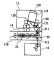
- the automatic teller machine 1 is configured with a box-shaped housing 2 as the center, and is installed in, for example, a financial institution, for example, a deposit process or a withdrawal process with a customer. Transactions related to cash.
- the housing 2 is provided with a customer-facing unit 3 at a location where it is easy to insert bills or operate with a touch panel while the customer is facing the front side.
- the customer reception unit 3 directly exchanges cash and cards, for example, with the customer, and is also configured to receive information about transactions and accept operational instructions.
- the card entry / exit port 4, the deposit / withdrawal port 5, An operation display unit 6, a numeric keypad 7, and a receipt issuing port 8 are provided.
- Card entry / exit 4 is a portion where various cards such as cash cards are inserted or ejected.
- a card processing unit (not shown) for reading account numbers and the like magnetically recorded on various cards is provided on the back side of the card slot 4.
- the deposit / withdrawal port 5 discharges the banknotes withdrawn to the customer as well as the banknotes deposited by the customer.
- the deposit / withdrawal port 5 is opened or closed by driving a shutter.
- the banknote is comprised, for example with the rectangular paper.
- the operation display unit 6 is a touch panel in which an LCD (Liquid Crystal Display) for displaying an operation screen at the time of a transaction and a touch sensor for inputting a transaction type, a password, a transaction amount, and the like are integrated.
- the numeric keypad 7 is a physical key that accepts input of numbers such as “0” to “9”, and is used when an input operation such as a password or transaction amount is performed.
- the receipt issuing port 8 issues a receipt on which transaction details are printed at the end of transaction processing.
- a receipt processing unit (not shown) for printing transaction contents and the like on the receipt is provided on the back side of the receipt issuing port 8.
- the side of the automated teller machine 1 facing the customer is the front side, the opposite is the rear side, the left and right are the left side and the right side as viewed from the customer facing the front side, and the upper side and the lower side. Is defined and explained.
- a main control unit 9 that performs overall control of the entire automatic teller machine 1, a banknote depositing and dispensing machine 10 that performs various processes related to banknotes, and the like.
- the main control unit 9 is configured around a CPU (Central Processing Unit) (not shown), and reads and executes a predetermined program from a ROM (Read Only Memory), a flash memory, etc. (not shown), thereby executing deposit processing and output.
- Various processing such as gold processing is performed.
- the main control unit 9 includes a storage unit including a RAM (Random Access Memory), a hard disk drive, a flash memory, and the like, and stores various information in the storage unit.
- the banknote depositing and dispensing machine 10 includes a plurality of portions that perform various processes relating to banknotes as a medium.
- the banknote depositing / dispensing machine 10 is roughly divided into an upper block 10U that occupies an upper part of the vertical center and a lower block 10L that closes the lower part.
- the upper block 10U includes a banknote control unit 11 that performs overall control, a deposit / withdrawal unit 12 that exchanges banknotes with customers, a transport unit 13 that transports banknotes to each unit, a discrimination unit 14 that discriminates banknotes, and banknotes.
- Temporary holding unit 15 for temporarily storing and counterfeit bill storage 18 for storing banknotes discriminated from counterfeit bills are provided.
- the banknote control unit 11 is configured around a CPU (not shown) as in the case of the main control unit 9, and determines a banknote transport destination by reading and executing a predetermined program from a ROM or flash memory (not shown). Various processes such as a process and a process for controlling the operation of each unit are performed. Moreover, the banknote control part 11 has a memory
- the deposit / withdrawal unit 12 is located at the upper front in the upper block 10U.
- This depositing / withdrawing unit 12 has a container 12A for accommodating banknotes deposited by customers and banknotes to be withdrawn to customers, and the upper part thereof can be opened and closed by a shutter 12B.
- a plurality of banknotes are accommodated in the container 12A in a state in which the paper sheets are stacked with the paper surface facing in the front-rear direction, that is, in a state aligned along the front-rear direction.
- the depositing / dispensing unit 12 includes a taking-in unit 12C and a discharging unit 12D respectively disposed before and after the lower end of the container 12A, and a depositing / dispensing transport unit 12E that transports bills and switches the transport path. Yes.
- the deposit / withdrawal unit 12 When taking in banknotes in the container 12A, the deposit / withdrawal unit 12 separates the banknotes in the container 12A one by one by the taking-in part 12C, and feeds them downward at predetermined time intervals. It is transferred to the transport unit 13 via 12E. Further, when the banknotes are sequentially delivered from the transport unit 13, the deposit / withdrawal unit 12 sequentially transports the banknotes to the discharge unit 12D by the deposit / withdrawal transport unit 12E, and sequentially discharges the banknotes into the container 12A by the discharge unit 12D. And accumulate.
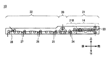
- the transport unit 13 is positioned at the lower end portion in the upper block 10U, that is, so as to traverse the vertical center of the entire bill depositing / dispensing machine 10 in the front-rear direction, and is generally thin in the vertical direction and elongated in the front-rear direction. It has become.
- a large number of rotating rollers, guides for guiding banknotes, and the like are appropriately arranged in the transporting unit 13, and the linear shape that transports mainly along the front-rear direction with the short direction of the banknote as the traveling direction.
- the conveyance path is formed.
- Each switching unit is constituted by a member called a blade (shown by a triangle in the figure) and a plurality of rollers arranged around the member.
- the blade is long in the left-right direction and is formed in a wedge shape when viewed from the left-right direction.
- the blade is driven by a rotary actuator, which will be described later, and is rotated to change the inclination direction, thereby switching the bill conveyance direction in two ways.
- Each roller is arrange
- the transport unit 13 is roughly composed of a first transport unit 21 on the front side, a second transport unit 22 on the rear side, and a temporary hold switching unit 20 that connects the two. ing.
- the temporary holding switching unit 20 is configured as a so-called three-way blade by a blade positioned at the center and rollers positioned on the front side, the rear side, and the upper side of the blade.
- the 1st switching part 24 is arrange
- the rear portion of the discrimination unit 14 in the first transport unit 21 is also referred to as a rear portion 21B.
- the 2nd switching part 25, the 3rd switching part 26, the 4th switching part 27, and the fake note switching part 28 are arrange
- route in the 2nd conveyance part 22 functions also as the conveyance path
- the discrimination unit 14 incorporates a plurality of types of sensors, recognizes the denomination, authenticity, correctness (whether or not it is damaged), etc., of the banknotes being conveyed, and determines the recognition result as a banknote control unit. 11 (details will be described later).
- the temporary storage unit 15 employs a so-called tape escrow method, and stores the banknotes by winding the banknotes together with the tape on the peripheral side surface of the cylindrical drum, and the banknotes by peeling the tape from the peripheral side surface. It comes to pay out.
- the fake ticket storage 18 is provided in a position near the rear end in the upper block 10U and immediately above the transport unit 13, and has a space for storing bills therein.
- a counterfeit banknote a banknote determined as a forged banknote (hereinafter referred to as a counterfeit banknote) by the discrimination section 14 and the banknote control section 11 to be described later is transported by the transport section 13, the counterfeit storage 18 stores this. .
- the transport unit 13 forms a linear transport path along the front-rear direction by the first transport unit 21, the temporary holding switching unit 20, and the second transport unit 22, and the banknotes are mainly transferred along the transport path.
- the transport path is switched by a plurality of switching units.
- the lower block 10L is covered with a strong safe casing 10S on all peripheral sides thereof.
- a reject box 16 for storing banknotes that should not be reused and five banknote storage boxes 17 (17A, 17B, 17C, 17D and 17E) for storing reusable banknotes.
- chamber 16 and the banknote storage 17 are comprised so that attachment or detachment with respect to the safe housing
- the reject box 16 is located on the foremost side in the lower block 10L, is formed in a rectangular parallelepiped shape that is long in the vertical direction, and has a space for collecting and storing banknotes therein.
- the reject box 16 stores the banknote therein.
- Each banknote storage 17 is configured in the same manner, and is formed in a rectangular parallelepiped shape that is long in the vertical direction and has a space for accumulating and storing banknotes therein.
- Each banknote storage 17 has a preset denomination of banknotes to be stored.
- the banknote storage 17 is transported by the transport unit 13 according to the denomination of the banknotes determined by the discrimination unit 14 and the banknote control unit 11 that the degree of damage is small and can be reused.
- the banknotes are collected and stored inside. Moreover, if the banknote storage 17 receives the instruction
- a conveyance guide 30 is arranged in the discrimination section 14 so as to tie approximately the center in the vertical direction along the front-rear direction.
- the conveyance guide 30 includes an upper conveyance guide 30A on the upper side and a lower conveyance guide 30B on the lower side.
- the upper conveyance guide 30A and the lower conveyance guide 30B are both made of a resin material, and a gap of about 5 mm is formed between the lower surface of the upper conveyance guide 30A and the upper surface of the lower conveyance guide 30B, and this gap is conveyed.
- the route is W1.
- short conveyance paths W2 and W3 respectively extending in the vertical direction from the branch point P1 which is the front end of the conveyance path W1 are formed by the conveyance guide 30 at the front end portion in the discrimination unit 14.
- the transport path W2 is connected to the upper deposit / withdrawal unit 12 (FIG. 2) at the upper end. Further, the transport path W3 is connected to the reject container 16 (FIG. 2) at the lower end.
- a transport roller 31 is disposed near the upper end of the transport path W2.
- the transport roller 31 is a group of rollers each having a short cylindrical or disc-shaped roller with a central axis directed in the left-right direction and arranged discretely in the left-right direction, one pair before and after the transport path W2. It arrange
- one of the roller pairs is rotationally driven clockwise or oppositely in the figure by supplying a driving force from a power source (not shown), and the other is driven to rotate.
- a transport roller 32 is disposed near the lower end of the transport path W3.
- the transport roller 32 is configured in the same manner as the transport roller 31, and a pair of rollers is arranged so as to sandwich the transport path W3 from the front-rear direction.
- the detection guide, the conveyance roller, the switching unit, and the like are provided in the conveyance guide 30 so as to be sequentially arranged along the conveyance path W1.
- a reject switching unit 23 is disposed in the vicinity of the front end (that is, the branch point P1) of the transport path W1. Behind the reject switching unit 23, in order from the front side along the conveyance path W1, the conveyance roller 33, the magnetic detection unit 34, the conveyance roller 35, the light emission detection unit 36, the conveyance roller 37, the thickness detection unit 38, and the conveyance A roller 39 is arranged. Further, the reject switching unit 23 is provided with a blade 42 that switches the banknote traveling direction at a position between the transport roller 31 and the transport roller 33 (details will be described later).
- the transport rollers 33, 35, 37 and 39 are configured in the same manner as the transport rollers 31 and 32, respectively. Further, between the transport rollers 33 and 35, between the transport rollers 35 and 37, between the transport rollers 37 and 39, between the transport rollers 33 and 31, and between the transport rollers 33 and 32, the transport path W1, W2, or W3 The distance along the length is shorter than the length along the traveling direction of the banknote, that is, the length of the short side.
- the discriminating unit 14 rotates each of the transport rollers 31, 32, 33, 35, 37, and 39 (hereinafter collectively referred to as a discrimination transport roller group), so that the banknote is always one of the transport rollers. Can be transferred to each other while being sandwiched between them, and can be transported along the transport path W1, W2 or W3.
- a magnetic sensor 34A is disposed above the transport path W1, and a contact roller 34B is disposed below the transport path W1.
- the magnetic sensor 34A detects magnetism from the banknote when a banknote transported along the transport path W1 by the differential transport roller group is pressed by the contact roller 34B, and the detection result is detected by the banknote control unit 11 (FIG. 2). To send.
- the magnetic sensor 34A has a relatively high sensitivity so as to detect weak magnetism contained in the banknote. For this reason, when there is a member that generates magnetism or a member that rotates or moves in a magnetized state around the magnetic sensor 34A, the magnetic sensor 34A may be affected by the magnetism and may not be able to correctly detect the magnetism of the bill. sell.
- the light emission detection unit 36 includes optical modules 36A and 36B arranged so as to face each other with the transport path W1 sandwiched from above and below.
- the optical modules 36 ⁇ / b> A and 36 ⁇ / b> B are configured similarly to each other, and incorporate a light emitting element that emits light, such as an LED (Light Emitting Diode), and a light receiving element that receives the light.
- the optical modules 36A and 36B are arranged so that one light emitting element and the other light receiving element face each other.
- the light receiving element is an imaging element formed linearly along the left-right direction.
- the light emission detector 36 detects transmitted light and reflected light on both sides of the banknote transported on the transport path W1 by simultaneously or sequentially performing light emission and light reception in both the optical modules 36A and 36B.
- the detection result is sent to the banknote control unit 11 (FIG. 2).
- this detection result is obtained by imaging a banknote in a straight line along the left-right direction, and by connecting these along the transport direction, a planar image obtained by imaging the banknote can be obtained.
- the banknote control unit 11 is either a genuine banknote (so-called genuine note) or a counterfeit (so-called counterfeit) based on the detection results supplied from the magnetic sensor 34A and the light emission detection unit 36, respectively. And the denomination and degree of damage.
- the thickness detector 38 includes a movable roller 38A attached to the upper conveyance guide 30A so as to be movable in the vertical direction, a fixed roller 38B attached to the lower conveyance guide 30B and not movable in the vertical direction, and the vertical direction of the movable roller 38A. And a movement amount sensor 38C for detecting the movement amount to the.
- the thickness detection unit 38 sandwiches the bill between the movable roller 38A and the fixed roller 38B. At this time, the movable roller 38A moves upward by an amount of movement corresponding to the thickness of the sandwiched banknote.
- the movement amount sensor 38C detects the movement amount of the movable roller 38A and notifies the banknote control unit 11 (FIG. 2) of the detection result as the banknote thickness.
- the banknote control unit 11 Based on the detection result supplied from the thickness sensor, the banknote control unit 11 corresponds to the thickness of the banknotes being conveyed on the conveyance path W1, is equivalent to one sheet, or two sheets. It is judged whether it corresponds to the above. Thereby, the banknote control part 11 is not conveying a banknote, is normally conveying only one banknote, or is conveying two or more banknotes piled up (namely, is carrying out multiple feeding). Can be recognized.
- the movable roller 38A and the fixed roller 38B are made of a material that is not easily deformed, for example, a metal material, in order to accurately detect the thickness of an extremely thin banknote, for example, about 0.1 mm.
- a metal material often has magnetism, and the surrounding magnetic field can be changed with its rotation.
- the light emission detection unit 36 is disposed between the magnetic detection unit 34 and the thickness detection unit 38, and the magnetic detection unit 34 and the thickness detection unit 38 are separated as much as possible in the front-rear direction, thereby moving the movable roller.
- the influence of magnetism on the magnetic sensor 34A of the magnetic detection unit 34 by the 38A and the fixed roller 38B is suppressed as much as possible.
- the reject switching unit 23 is roughly composed of a rotary actuator 41, a blade 42, and a magnetic shield 43.
- the rotary actuator 41 has a configuration in which a solenoid coil 46 is incorporated in a frame 45 that covers the periphery, and an output shaft 47 is disposed so as to penetrate the inside and outside of the frame. It has become.
- the frame 45 is made of a metal material having magnetism, and is formed into a flat box shape that is relatively thin in the left-right direction by processing a plate-like member, and a space is provided therein.
- the solenoid coil 46 is formed of a so-called electromagnet, and generates a magnetic force when supplied with electric power. That is, the frame 45 can protect each component of the rotary actuator 41 from the outside and can shield the magnetic field generated by the solenoid coil 46 to some extent.
- a power transmission mechanism (not shown) is incorporated.
- the power transmission mechanism incorporates a magnet that can move in the front-rear direction, a member that rotates according to the position of the magnet, and the like. For this reason, this power transmission mechanism converts the magnetic force generated in the solenoid coil 46 into a driving force in the rotational direction and transmits it to the output shaft 47.
- the output shaft 47 is formed in a relatively short cylindrical shape with the central axis directed in the left-right direction, and rotates about the central axis in a range of, for example, about 45 degrees by the driving force transmitted from the transmission mechanism.
- the right end of the output shaft 47 protrudes to the left of the left side surface of the frame 45, that is, outward.
- the rotary actuator 41 aligns the vertical position (ie, height) of the center axis of the output shaft 47 with the substantially vertical center of the transport path W1.
- the rotary actuator 41 has the solenoid coil 46 positioned almost directly below the output shaft 47.
- the solenoid coil 46 is located on the opposite side of the magnetic sensor 34A across the transport path W1. For this reason, the distance L2 from the magnetic sensor 34A to the solenoid coil 46 is longer than the distance L1 from the magnetic sensor 34A to the output shaft 47.
- the blade 42 (FIG. 5) is formed in a triangular prism shape with the central axis directed in the left-right direction as a whole, and is an isosceles triangle shape or wedge shape with the apex angle directed rearward when viewed from the left-right direction.
- the blade 42 is penetrated in the left-right direction by the shaft 48 at a position near the center as viewed from the left-right direction.
- the shaft 48 is made of a metal material having magnetism, and is formed in an elongated cylindrical shape with the central axis directed in the left-right direction.
- the shaft 48 is supported by the conveyance guide 30 via a bearing 49 at the left end.
- the shaft 48 is connected to the output shaft 47 via the connecting member 50 at the right end. For this reason, like the output shaft 47, the shaft 48 and the connecting member 50 are positioned so that the vertical position (that is, the height) is substantially aligned with the vertical center of the transport path W1 (FIG. 7).
- the connecting member 50 is made of, for example, a resin material, and is physically connected without directly contacting the output shaft 47 and the shaft 48, that is, in a state where they are separated on the magnetic circuit.
- the blade 42 is integrated with the shaft 48, the connecting member 50, and the output shaft 47. For this reason, the blade 42 can rotate around the shaft 48 together with the output shaft 47 of the rotary actuator 41.
- the blade 42 is rotated so that the apex angle is positioned downward, so that the upper surface thereof is continuous with the upper surface of the lower transport guide 30B, and the transport path W1 and the transport path W2 And connect. Further, as shown by a broken line in FIG. 7, the blade 42 is rotated so that the apex angle is positioned upward, so that the lower surface thereof is continuous with the lower surface of the upper transport guide 30A, and the transport path W1 and the transport path W3 are connected. Connect.
- the reject switching unit 23 rotates the blade 42 by the rotary actuator 41 to connect the transport path W1 and the transport path W2 or connect the transport path W1 and the transport path W3.
- the transport route is switched.
- the magnetic shield 43 is formed in a rectangular cylindrical shape covering the front, rear, left and right of the rotary actuator 41, and the upper and lower surfaces thereof are open.
- the magnetic shield 43 is configured by bending a magnetic metal plate member, for example, a steel plate having a thickness of about 2 to 3 mm.
- the upper end of the magnetic shield 43 is higher than the upper end of the frame 45 in the rotary actuator 41, and the lower end thereof is lower than the lower end of the frame 45. Covering. That is, the magnetic shield 43 covers a range wider than the frame 45 of the rotary actuator 41 in the vertical direction.
- an insertion hole through which the output shaft 47 is inserted is formed on the upper side of the left side plate of the magnetic shield 43.
- the inner diameter of the insertion hole is sufficiently larger than the outer diameter of the output shaft 47, and the magnetic shield 43 and the output shaft 47 are avoided from contacting each other on the magnetic circuit.
- the magnetic shield 43 is fixed to the left side surface of the frame 45 of the rotary actuator 41 via the attachment member 51 on the inner surface (right surface) of the left side plate.
- the attachment member 51 is made of a nonmagnetic resin material.
- the magnetic shield 43 is fixed to the right side surface of the conveyance guide 30 on the outer surface (left surface) of the left side plate.
- the transport guide 30 is made of a nonmagnetic resin material.
- the magnetic shield 43 is separated on the magnetic circuit from any of the conveyance guide 30, each member attached thereto, and the frame 45 of the rotary actuator 41.
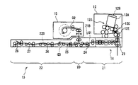
- FIGS. 9, 10, and 11 are enlarged views of the deposit / withdrawal unit 12, the transport unit 13, the discrimination unit 14, and the temporary storage unit 15 in the upper block 10 ⁇ / b> U of the banknote depositing / dispensing machine 10. .
- the banknote control unit 11 when the banknote control unit 11 receives an operation input for starting the deposit process via the operation display unit 6 (FIG. 1) by the customer, the bill control unit 11 starts the deposit counting process and the shutter 12 ⁇ / b> B of the deposit / withdrawal unit 12. Is opened and bills are inserted into the container 12A.
- the banknote control part 11 receives the operation input which starts taking in of a banknote via the operation display part 6, the shutter 12B will be closed and the banknote in the said container 12A will be isolate
- the first transport unit 21 sequentially transfers the banknotes received from the deposit / withdrawal unit 12 backward by the reject switching unit 23 of the discrimination unit 14. Moreover, the discrimination part 14 discriminates each banknote sequentially by each sensor, conveying a banknote back inside, and delivers the said banknote to the rear part 21B of the 1st conveyance part 21 from a back side, and the discrimination result is a banknote. It is sent to the control unit 11.
- the banknote control unit 11 first determines the degree of damage, denomination, or authenticity of each banknote based on the acquired discrimination result. Next, the banknote control unit 11 is a deposit acceptance banknote that can be recognized as a normal banknote for each banknote and can continue the subsequent processing, or is a deposit reject banknote that should be returned to the customer once because it cannot be recognized as a normal banknote. Determine whether.
- the banknote control part 11 carries out the rejection store
- the 1st conveyance part 21 switches a conveyance path
- the temporary hold switching unit 20 switches to a conveyance path according to the discrimination result for each banknote based on the control of the banknote control unit 11. Specifically, the temporary holding switching unit 20 advances and stores the deposit acceptance banknote and the counterfeit bill to the upper temporary holding unit 15 as indicated by the arrow Q2, and indicates the deposit reject banknote BL by the arrow Q3. In this way, it is advanced into the second transport unit 22 and stored in the transport path storage unit 22S.
- the banknote control unit 11 finishes taking in all banknotes from the container 12A of the deposit / withdrawal unit 12, if the deposit reject banknote BL is stored in the transport path storage unit 22S, this is indicated by an arrow Q4. It is conveyed to the deposit / withdrawal unit 12 (that is, reversely sent), returned to the customer, and confirmed and re-entered. On the other hand, the banknote control unit 11 completes the deposit counting process if the deposit reject banknote BL is not stored in the transport path storage unit 22S.
- the banknote control unit 11 calculates the deposit amount based on the total result of the denomination and the number of the banknotes taken in from the deposit / withdrawal unit 12 and displays a predetermined operation instruction screen on the operation display unit 6. The amount is presented to the customer and the customer is allowed to select whether or not to continue the deposit process.
- the banknote control unit 11 sequentially receives all banknotes held in the temporary holding unit 15 by the temporary holding switching unit 20, the first transport unit 21, and the discrimination unit 14 when the customer instructs to stop the deposit process. It is conveyed forward and returned into the container 12A of the deposit / withdrawal unit 12, and the shutter 12B is opened and returned to the customer.
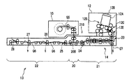
- the banknote control unit 11 starts the deposit storage process as shown in FIG. Specifically, the banknote control unit 11 first starts the maneuvering process in the temporary storage unit 15 to sequentially feed out the stored banknotes (payment acceptance banknotes) as indicated by the arrow Q5, and the temporary temporary storage switching downstream. Delivered to part 20.
- the banknote control unit 11 first starts the maneuvering process in the temporary storage unit 15 to sequentially feed out the stored banknotes (payment acceptance banknotes) as indicated by the arrow Q5, and the temporary temporary storage switching downstream. Delivered to part 20.
- the banknote control part 11 switches the conveyance path
- the banknote control part 11 conveys the said banknote to the said conveyance destination, and each accommodates it by controlling suitably each switching part of the 1st conveyance part 21 and the 2nd conveyance part 22 according to the conveyance destination of each banknote. .
- the banknote control part 11 stores the reject banknote which should not be reused in the rejection store
- the banknotes stored in each banknote storage 17 and banknotes determined to be counterfeit can be stored in the counterfeit storage 18.
- the banknote depositing / dispensing machine 10 stores the banknotes in the temporary storage unit while determining the transport destination of each banknote when the banknotes are identified in the preceding deposit counting process in the depositing process, and is instructed to continue the depositing process. In the subsequent deposit storage process, each banknote is transported to a transport destination that has already been determined.
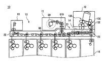
- the banknote control unit 11 first receives a predetermined operation input including a withdrawal amount from the customer via the operation display unit 6 (FIG. 1), and determines the denomination and number of banknotes according to the withdrawal amount. Subsequently, the banknote control unit 11 pays out the banknotes stored in a state of being accumulated in each banknote storage 17 according to the determined denomination and number, and separates the banknotes one by one for downstream first conveyance. The paper is sequentially transferred to the unit 21 or the second transport unit 22.
- the banknote control unit 11 appropriately forwards the banknotes stored in the banknote storages 17B to 17E by appropriately switching the switching units of the second transport unit 22 as indicated by an arrow Q8, and temporarily holding the banknotes.
- the first transfer unit 21 is transferred via the switching unit 20.
- the banknote control unit 11 stores the banknote stored in the banknote storage 17A once in the temporary storage unit 15 via the temporary storage switching unit 20, as indicated by the arrow Q9, and then as indicated by the arrow Q10.
- the temporary storage unit 15 is sequentially advanced to advance forward in the first transport unit 21.
- the banknote control part 11 discriminates the banknote which advances the inside of the 1st conveyance part 21 by the discrimination part 14, and sends out the discrimination result to the banknote control part 11 (FIG. 2). In response to this, the banknote control unit 11 determines the transport destination as the deposit / withdrawal unit 12 or the reject box 16 according to the discrimination result of the banknote.
- the banknote control unit 11 As shown in FIG. 13, the upper deposit / withdrawal unit 12 and the rear discrimination unit in the reject switching unit 23 of the first transport unit 21. 14 is formed, and as shown by an arrow Q11, the banknote is conveyed to the downstream depositing / dispensing portion 12 and discharged into the container 12A.
- the reject switching unit 23 connects the rear discrimination unit 14 and the lower reject box 16. A path is formed, and the bill is conveyed to and stored in the downstream reject box 16 as indicated by an arrow Q12.
- the discrimination unit 14 detects the running state by the thickness detection unit 38 located on the upstream side, sends the detection result to the banknote control unit 11 (FIG. 2), and then the light emission detection unit 36 located on the downstream side. And the detection result by the magnetic detection part 34 is sent to the banknote control part 11.
- FIG. 1 the banknote control part 11 acquires the detection result by the light emission detection part 36 and the magnetic detection part 34, after determining the conveyance destination of each banknote according to a driving
- the banknote control part 11 when it is detected by the light emission detection part 36 and the magnetic detection part 34 that the banknote is not normal and should not be withdrawn, the banknote control part 11 is in the process of conveying as shown by an arrow Q13 in FIG. 14A.
- the banknote is stopped immediately, that is, in the middle of being conveyed by the depositing / dispensing conveyance unit 12E of the discrimination unit 14 or the depositing / dispensing unit 12.
- the banknote control unit 11 reversely feeds the banknote to the rear side of the discrimination unit 14, and then sets the transport destination of the banknote as the reject box 16 and rejects it.
- the switching unit 23 is switched and conveyed to the reject box 16 as indicated by an arrow Q15.
- the shutter 12B is opened to allow the customer to take out the banknotes.
- the banknote depositing / dispensing machine 10 deposits / withdraws banknotes according to the withdrawal amount from each banknote storage 17 while switching the transport path by the reject switching unit 23 based on the discrimination result by the discrimination unit 14 in the withdrawal process. It is transported to the section 12 and delivered to the customer.
- the banknote depositing and dispensing machine 10 of the automatic teller machine 1 incorporates the discrimination unit 14 in the first transport unit 21 located on the front side of the transport unit 13.
- the discrimination unit 14 a discrimination conveyance roller group and a plurality of detection units are arranged, and in addition to this, a reject switching unit 23 is arranged.
- the thickness detection unit 38 is arranged on the rearmost side in order to detect an abnormality in conveyance such as double feeding at the earliest stage in the withdrawal process.
- the magnetic detection part 34 is arrange
- the length in the longitudinal direction of the first conveyance unit 21 of the conveyance unit 13 is set in the discrimination unit 14 in order to meet the demand for minimization as much as possible.
- the reject switching unit 23 is arranged in the area.
- the rotary actuator 41 of the reject switching unit 23 is arranged at a location relatively close to the magnetic sensor 34A of the magnetic detection unit 34.
- the magnetic sensor 34A may detect the magnetism generated by the solenoid coil 46 in the rotary actuator 41 as magnetic noise.
- the magnetic shield 43 is disposed so as to surround the front, rear, left and right of the rotary actuator 41 in the reject switching unit 23 (FIG. 5).
- the discrimination part 14 can shield effectively the magnetism which generate
- the discrimination unit 14 can arrange the rotary actuator 41 and the magnetic sensor 34A closer to each other by arranging the magnetic shield 43. This can contribute to downsizing and further downsizing of the banknote depositing and dispensing machine 10 and the automatic teller machine 1.
- the magnetic shield 43 is provided by the attachment member 51 so as to be spaced apart from the frame 45 of the rotary actuator 41 by a certain amount. For this reason, the discrimination part 14 can suppress the fall of the shielding effect of a magnetic field by making it hard to generate
- the magnetic shield 43 is directly brought into contact only with the resin conveyance guide 30 and the mounting member 51, and is not brought into contact with other members, particularly magnetic metal members. For this reason, the discrimination part 14 can isolate
- the discrimination unit 14 inevitably determines the positions of the blades 42 with respect to the transport paths W1, W2, and W3, and accordingly, the positions of the shaft 48 and the output shaft 47 are also determined.
- the rejection switching part 23 is arrange
- the solenoid coil 46 is positioned almost directly below the output shaft 47 in the rotary actuator 41. This means that the solenoid coil 46 is disposed at a position farthest from the magnetic sensor 34A among positions that can be disposed under various restrictions in the discrimination unit 14. For this reason, the discrimination unit 14 can minimize the influence of the magnetic field exerted on the magnetic sensor 34A from the solenoid coil 46.
- the magnetic shield 43 is arranged in the discrimination portion 14 to be configured as small as possible so as to be spaced apart from the frame 45 of the rotary actuator 41 in the front, rear, left and right directions (FIG. 5). For this reason, the magnetic shield 43 is less likely to cause magnetic saturation as compared with the case where the magnetic shield 43 is disposed in the immediate vicinity of the frame 45, and a part of the magnetic field can be returned to the frame 45 side without reaching the magnetic shield 43. it can.
- the magnetic shield 43 does not require a structure that enhances the shielding effect of the magnetic field more than necessary, for example, using a material with high magnetic permeability or processing a plate member having a large thickness.
- the required cost can be kept low.
- the banknote depositing and dispensing machine 10 of the automatic teller machine 1 incorporates the discrimination unit 14 in the first conveyance unit 21 located on the front side of the conveyance unit 13, and the discrimination conveyance roller group in the discrimination unit 14.
- a plurality of detection units are arranged, and in addition to this, a reject switching unit 23 is arranged.
- a magnetic shield 43 is disposed so as to surround the front, rear, left and right of the frame 45 in the rotary actuator 41.
- the discrimination unit 14 is forced to place the rotary actuator 41 at a position relatively close to the magnetic sensor 34A of the magnetic detection unit 34 due to size and arrangement restrictions.
- the magnetic field generated by the solenoid coil 46 is shielded from the magnetic shield. 43 can be effectively shielded, and the possibility of affecting the magnetic sensor 34A as magnetic noise can be greatly reduced.
- the magnetic sensor 34A of the magnetic detection unit 34 is disposed above the transport path W1, and the output shaft 47 is disposed below the transport path W1, that is, on the opposite side across the transport path W1.
- the case where the solenoid coil 46 is disposed at a position almost directly below the distance L2 and the distance L2 is made larger than the distance L1 has been described.
- the solenoid coil 46 may be disposed at a position substantially deviated from directly below the output shaft 47, or the solenoid coil 46 is the same as the upper side of the transport path W1, that is, the transport path W1. It may be arranged on the side. In this case, the distance L2 may be smaller than the distance L1. In these cases, it is only necessary that the magnetic shield 43 can sufficiently reduce the influence of magnetism from the rotary actuator 41 to the magnetic sensor 34 ⁇ / b> A. *
- the magnetic shield 43 is attached to the conveyance guide 30 .
- the present disclosure is not limited to this, and may be fixed to various members such as a member constituting the outer shell of the discrimination unit 14, or may be fixed only to the frame 45 by the mounting member 51. good. Further, when fixing to another member, it is desirable to separate the magnetic shield 43 from another magnetic material on the magnetic circuit, for example, by attaching via an intermediate member made of resin.
- the attachment member 51 having a rectangular parallelepiped shape is interposed between the left side surface of the frame 45 and the inner side surface of the left side plate of the magnetic shield 43, and the magnetic shield 43 is fixed to the frame 45.
- the present disclosure is not limited to this.
- a hollow prismatic mounting member that fills a gap with the magnetic shield 43 on each of the front, back, left, and right sides of the frame 45 is configured, and the frame 45 is connected to the frame 45 via the mounting member.
- the magnetic shield 43 may be fixed. In this case, the magnetic shield 43 may not be fixed to the transport guide 30.
- the frame 45 of the rotary actuator 41 is made of a magnetic material to have a function of shielding magnetism, and the upper end of the magnetic shield 43 is made higher than the upper end of the frame 45.
- the case where the lower end of the magnetic shield 43 is made lower than the lower end of the frame 45 has been described.
- the present disclosure is not limited to this.
- the upper end of the magnetic shield 43 may be lower than the upper end of the frame 45, and the lower end of the magnetic shield 43 may be higher than the lower end of the frame 45.
- the case where the upper and lower portions of the magnetic shield 43 are opened and the magnetism is shielded only on the front, rear, left and right side surfaces has been described.
- the present disclosure is not limited to this.
- the upper and lower portions of the magnetic shield 43 may be closed.
- the shaft 48 is made of a magnetic material and is connected by the connecting member 50 made of a nonmagnetic material so that the shaft 48 and the output shaft 47 are not in direct contact with each other has been described.
- the present disclosure is not limited to this.
- the shaft 48 may be made of a nonmagnetic material, and the shaft 48 and the output shaft 47 may be connected to each other by the connecting member 50.
- the present disclosure is not limited to this.
- the present disclosure may be applied to a banknote processing apparatus (so-called teller machine) or the like that is installed at a window of a financial institution and is mainly used by employees of the financial institution.
- the present disclosure may be applied to various apparatuses that handle various paper-like media such as various kinds of money vouchers and securities, or admission tickets and boarding tickets.
- the present disclosure is not limited to the above-described embodiments and other embodiments.
- the present disclosure covers the scope of the embodiment in which some or all of the above-described embodiments and other embodiments described above are arbitrarily combined, or the embodiment in which some are extracted. It is.
- the conveyance rollers 35, 33 and 31 as the first, second and third conveyance rollers, the magnetic sensor 34A as the magnetic sensor, the blade 42 as the blade, and the magnetic shield The case where the medium discrimination device is configured by the magnetic shield 43 and the mounting member 51 as the support has been described.
- the present disclosure is not limited to this, and a medium discrimination device is configured by the first, second, and third transport rollers, the magnetic sensor, the blade, the magnetic shield, and the support that have various other configurations. Also good.
- This disclosure can also be used in an automated teller machine or the like that performs transaction processing related to banknote deposits and withdrawals with customers.
Landscapes
- Physics & Mathematics (AREA)
- General Physics & Mathematics (AREA)
- Inspection Of Paper Currency And Valuable Securities (AREA)
- Separation, Sorting, Adjustment, Or Bending Of Sheets To Be Conveyed (AREA)
Priority Applications (1)
| Application Number | Priority Date | Filing Date | Title |
|---|---|---|---|
| CN201580033470.0A CN106463009B (zh) | 2014-07-31 | 2015-06-18 | 介质鉴别装置和介质处理装置 |
Applications Claiming Priority (2)
| Application Number | Priority Date | Filing Date | Title |
|---|---|---|---|
| JP2014-155704 | 2014-07-31 | ||
| JP2014155704A JP6303898B2 (ja) | 2014-07-31 | 2014-07-31 | 媒体鑑別装置及び媒体処理装置 |
Publications (1)
| Publication Number | Publication Date |
|---|---|
| WO2016017316A1 true WO2016017316A1 (ja) | 2016-02-04 |
Family
ID=55217221
Family Applications (1)
| Application Number | Title | Priority Date | Filing Date |
|---|---|---|---|
| PCT/JP2015/067640 Ceased WO2016017316A1 (ja) | 2014-07-31 | 2015-06-18 | 媒体鑑別装置及び媒体処理装置 |
Country Status (3)
| Country | Link |
|---|---|
| JP (1) | JP6303898B2 (https=) |
| CN (1) | CN106463009B (https=) |
| WO (1) | WO2016017316A1 (https=) |
Families Citing this family (2)
| Publication number | Priority date | Publication date | Assignee | Title |
|---|---|---|---|---|
| CN108573564B (zh) * | 2017-03-13 | 2021-08-24 | 山东新北洋信息技术股份有限公司 | 纸币处理装置及纸币处理方法 |
| KR102545829B1 (ko) * | 2021-03-17 | 2023-06-20 | 주식회사 케이티앤지 | 에어로졸 생성 장치 |
Citations (2)
| Publication number | Priority date | Publication date | Assignee | Title |
|---|---|---|---|---|
| JPS63278193A (ja) * | 1987-05-11 | 1988-11-15 | 沖電気工業株式会社 | 循環式紙幣入出金装置 |
| JP2003054811A (ja) * | 2001-08-13 | 2003-02-26 | Oki Electric Ind Co Ltd | 搬送方向切替装置と媒体表裏反転収納装置 |
Family Cites Families (6)
| Publication number | Priority date | Publication date | Assignee | Title |
|---|---|---|---|---|
| JPS59191688A (ja) * | 1983-04-15 | 1984-10-30 | 株式会社東芝 | 紙葉類の磁性検知装置 |
| CN201255890Y (zh) * | 2008-09-22 | 2009-06-10 | 管洪安 | 点钞机专用磁头与磁头屏蔽罩装置 |
| JP5375912B2 (ja) * | 2011-09-22 | 2013-12-25 | 沖電気工業株式会社 | 媒体鑑別装置及び媒体取引装置 |
| CN202632400U (zh) * | 2012-03-08 | 2012-12-26 | 上海理工大学 | 设有货币面值识别器的验钞机 |
| CN103839320A (zh) * | 2012-11-23 | 2014-06-04 | 北京嘉岳同乐极电子有限公司 | 用于金融鉴伪机的磁传感器及其制作方法 |
| CN103646462A (zh) * | 2013-07-25 | 2014-03-19 | 浙江方泰电器有限公司 | 一种卧式纸币清分机 |
-
2014
- 2014-07-31 JP JP2014155704A patent/JP6303898B2/ja not_active Expired - Fee Related
-
2015
- 2015-06-18 CN CN201580033470.0A patent/CN106463009B/zh not_active Expired - Fee Related
- 2015-06-18 WO PCT/JP2015/067640 patent/WO2016017316A1/ja not_active Ceased
Patent Citations (2)
| Publication number | Priority date | Publication date | Assignee | Title |
|---|---|---|---|---|
| JPS63278193A (ja) * | 1987-05-11 | 1988-11-15 | 沖電気工業株式会社 | 循環式紙幣入出金装置 |
| JP2003054811A (ja) * | 2001-08-13 | 2003-02-26 | Oki Electric Ind Co Ltd | 搬送方向切替装置と媒体表裏反転収納装置 |
Also Published As
| Publication number | Publication date |
|---|---|
| CN106463009A (zh) | 2017-02-22 |
| CN106463009B (zh) | 2019-06-21 |
| JP2016033700A (ja) | 2016-03-10 |
| JP6303898B2 (ja) | 2018-04-04 |
Similar Documents
| Publication | Publication Date | Title |
|---|---|---|
| JP6252056B2 (ja) | 紙幣入出金装置及び紙幣取引装置 | |
| JP6409502B2 (ja) | 媒体処理装置及び媒体取引装置 | |
| JP5795990B2 (ja) | 紙葉類取扱装置及び自動取引装置 | |
| WO2016038963A1 (ja) | 媒体処理装置及び媒体取引装置 | |
| WO2013140686A1 (ja) | 媒体収納繰出装置及び媒体取引装置 | |
| US11535477B2 (en) | Medium processing device and automatic transaction device | |
| JP2014112440A (ja) | 媒体取引装置 | |
| JP6561657B2 (ja) | 紙葉類処理装置及び紙葉類鑑別装置 | |
| JPH09147193A (ja) | 紙幣入出金装置 | |
| JP6303898B2 (ja) | 媒体鑑別装置及び媒体処理装置 | |
| JP7218507B2 (ja) | 媒体処理装置及び自動取引装置 | |
| JP5834849B2 (ja) | 媒体搬送装置及び媒体取引装置 | |
| JP6237911B2 (ja) | 媒体搬送識別装置及び媒体取引装置 | |
| JP7647370B2 (ja) | 媒体処理装置及び媒体取引装置 | |
| JP5277757B2 (ja) | 紙幣処理装置 | |
| JP2021056554A (ja) | 現金処理装置 | |
| KR101969860B1 (ko) | 환류식 금융자동화기기의 수표/지폐 입출금장치 및 그 운영방법 | |
| JP2010231262A (ja) | 紙葉取扱装置 | |
| JP6409525B2 (ja) | 帯電防止機構及び媒体取引装置 | |
| JP2015036933A (ja) | 媒体集積装置及び媒体取引装置 | |
| JPS6222195A (ja) | 紙幣入金装置 | |
| JP7226039B2 (ja) | 媒体処理装置及び自動取引装置 | |
| JP2016057687A (ja) | 媒体処理装置 | |
| JP2014016717A (ja) | 媒体処理装置及び媒体処理プログラム | |
| JP2017010149A (ja) | 媒体処理装置および自動取引装置 |
Legal Events
| Date | Code | Title | Description |
|---|---|---|---|
| 121 | Ep: the epo has been informed by wipo that ep was designated in this application |
Ref document number: 15827464 Country of ref document: EP Kind code of ref document: A1 |
|
| NENP | Non-entry into the national phase |
Ref country code: DE |
|
| 122 | Ep: pct application non-entry in european phase |
Ref document number: 15827464 Country of ref document: EP Kind code of ref document: A1 |