WO2016017029A1 - 部品装着方法および部品装着装置 - Google Patents
部品装着方法および部品装着装置 Download PDFInfo
- Publication number
- WO2016017029A1 WO2016017029A1 PCT/JP2014/070345 JP2014070345W WO2016017029A1 WO 2016017029 A1 WO2016017029 A1 WO 2016017029A1 JP 2014070345 W JP2014070345 W JP 2014070345W WO 2016017029 A1 WO2016017029 A1 WO 2016017029A1
- Authority
- WO
- WIPO (PCT)
- Prior art keywords
- component
- clamping
- mounting
- data
- standard
- Prior art date
Links
Images


Classifications
-
- H—ELECTRICITY
- H05—ELECTRIC TECHNIQUES NOT OTHERWISE PROVIDED FOR
- H05K—PRINTED CIRCUITS; CASINGS OR CONSTRUCTIONAL DETAILS OF ELECTRIC APPARATUS; MANUFACTURE OF ASSEMBLAGES OF ELECTRICAL COMPONENTS
- H05K13/00—Apparatus or processes specially adapted for manufacturing or adjusting assemblages of electric components
- H05K13/04—Mounting of components, e.g. of leadless components
- H05K13/046—Surface mounting
-
- H—ELECTRICITY
- H05—ELECTRIC TECHNIQUES NOT OTHERWISE PROVIDED FOR
- H05K—PRINTED CIRCUITS; CASINGS OR CONSTRUCTIONAL DETAILS OF ELECTRIC APPARATUS; MANUFACTURE OF ASSEMBLAGES OF ELECTRICAL COMPONENTS
- H05K13/00—Apparatus or processes specially adapted for manufacturing or adjusting assemblages of electric components
- H05K13/04—Mounting of components, e.g. of leadless components
- H05K13/0404—Pick-and-place heads or apparatus, e.g. with jaws
- H05K13/0408—Incorporating a pick-up tool
-
- H—ELECTRICITY
- H05—ELECTRIC TECHNIQUES NOT OTHERWISE PROVIDED FOR
- H05K—PRINTED CIRCUITS; CASINGS OR CONSTRUCTIONAL DETAILS OF ELECTRIC APPARATUS; MANUFACTURE OF ASSEMBLAGES OF ELECTRICAL COMPONENTS
- H05K13/00—Apparatus or processes specially adapted for manufacturing or adjusting assemblages of electric components
- H05K13/08—Monitoring manufacture of assemblages
- H05K13/085—Production planning, e.g. of allocation of products to machines, of mounting sequences at machine or facility level
- H05K13/0853—Determination of transport trajectories inside mounting machines
Definitions
- the present invention relates to a component mounting method and a component mounting apparatus for mounting a plurality of components on a board, and more particularly, to a method and apparatus for avoiding that a component mounting tool for clamping a component interferes with a mounted component.
- the component mounting machine includes a substrate transfer device, a component supply device, and a component transfer device.
- the component transfer device has a component mounting tool that transports and mounts a component collected from the component supply device to a positioned substrate, and a drive mechanism that drives the component mounting device.
- a typical example of the component mounting tool is a suction nozzle of a type that sucks a component using negative pressure.
- the suction position at which the suction nozzle sucks a component is determined in advance based on the shape of each component. Normally, the suction position of each part is set to the center of the body of the part, whereby the part is sucked above the center of gravity, so that the suction operation and the mounting operation are stabilized.
- the holder in the component mounting method of Patent Document 1, when the holder (suction nozzle) protrudes from the side end surface of the mounted component and there is an existing component (mounted component) adjacent to the mounting position, the holder interferes with the existing component.
- the offset amount for not performing the calculation is obtained, and the component supply unit (component supply position) and the holder are offset by the offset amount when the holder holds the mounted component. According to this, even if the mounting conditions are such that the parts are closely spaced, interference can be avoided and a reduction in productivity can be suppressed.
- the surface mounter disclosed in Patent Document 2 also includes interference prevention processing control means similar to the technique disclosed in Patent Document 1.
- JP 2002-335097 A Japanese Patent No. 4896757
- the component mounting tool includes a mounting tool of a type in which a part is clamped by a plurality of claw portions, and a so-called mechanical chuck nozzle.
- a type of mounting tool that selects and functions the suction by the negative pressure and the clamping by the claw portion in other words, a mounting tool that has both the suction nozzle and the mechanical chuck nozzle (commonly known as an OF Crow nozzle).
- the mechanical chuck nozzle the plurality of claw portions that sandwich the side surface of the component always protrude from the component, expand by an opening operation at the time of mounting, and further protrude from the component. Therefore, the interference with the mechanical chuck nozzle mounted component tends to be expected to occur more frequently than the suction nozzle interference disclosed in Patent Documents 1 and 2, and the avoidance method is difficult.
- one suction position of the component is determined, whereas in the mechanical chuck nozzle, a plurality of clamping positions of the component are determined. That is, the method for designating the relative positional relationship between the mechanical chuck nozzle and the parts is different from that of the suction nozzle. For this reason, even if the technique for avoiding the interference of the suction nozzle with the mounted parts is applied to the mechanical chuck nozzle as it is, it is not necessarily effective. For example, when the pair of claw portions of the mechanical chuck nozzle sandwich the two short sides of the rectangular component, it interferes with the mounted component, but there are cases where the interference can be avoided by sandwiching the two long sides. Such an avoidance method cannot be expressed by a method of designating one suction position.
- the present invention has been made in view of the problems of the background art described above, and when using a component mounting tool that sandwiches a component with a plurality of claw portions, the plurality of claw portions when the component is opened on a substrate. It is an object of the present invention to provide a component mounting method that can prevent a position and an opening operation from interfering with a mounted component so that the component can be mounted.
- the invention of the component mounting method according to claim 1 that solves the above-described problem is a plurality of components that are picked up by sandwiching a component at a component supply position, and the component is opened on a substrate to mount the component at a predetermined position on the substrate.
- a component mounting method using a component mounting tool that has a claw portion and is movably mounted between the component supply position and the substrate, and for a mounted component that is already mounted on the substrate thus, the clamping position of the component to be clamped by the plurality of claw portions is determined so that the positions and opening operations of the plurality of claw portions when the component is opened do not interfere with each other.
- a component mounting apparatus having a plurality of claw portions for picking up a component at a component supply position, opening the component on a substrate, and mounting the component at a predetermined position on the substrate.
- a component mounting apparatus comprising a component mounting device that is mounted so as to be movable between the component supply position and the substrate, wherein the component is attached to the mounted component that is already mounted on the substrate.
- the apparatus further includes a clamping position determining unit that determines a clamping position of the component that is clamped by the plurality of claw sections.
- the component mounting method it is possible to tentatively determine the clamping position of the component clamped by the plurality of claws based on the shape of the component to be mounted, the dimensions of each component, and the mounting coordinate position on the board. it can. Then, the position of the plurality of claw portions and the coordinate range of the opening operation when the component is released on the board can be obtained, and it can be determined whether or not it interferes with the mounted component. As a result of the determination, if there is no interference, a temporarily determined clamping location can be adopted, and if there is interference, the final clamping location can be determined so as not to interfere by changing the temporarily determined clamping location. Thereby, interference can be avoided and the part can be mounted.
- the invention of the component mounting method according to claim 1 can be implemented. Accordingly, the invention of the component mounting method according to claim 6 produces the same effect as that of the method invention according to claim 1.
- the component mounter includes a substrate transfer device, a component supply device, a component transfer device, and the like.
- the substrate transfer device carries in the substrate, positions it at the component mounting position, and carries out the substrate on which the component is mounted.
- the component supply device sequentially supplies components to the component supply position.
- the component supply device includes, for example, a plurality of feeder devices arranged in a row.
- the component transfer device conveys the component collected from the component supply position of the component supply device to the positioned substrate and mounts it at a predetermined mounting coordinate position on the substrate.
- the component transfer device includes an adsorption nozzle and a mechanical chuck nozzle 1, a mounting head 9, and an XY drive mechanism.
- the suction nozzle and the mechanical chuck nozzle 1 are attached to the mounting head 9 in a replaceable manner. Without being limited thereto, the suction nozzle and the mechanical chuck nozzle 1 may be attached to separate mounting heads, or may be mounted side by side on one mounting head.
- the mounting head 9 is movably mounted on an XY drive mechanism.
- the XY drive mechanism drives the mounting head 9 in two horizontal directions to move the suction nozzle and the mechanical chuck nozzle 1 between the component supply position and the substrate.
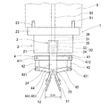
- FIG. 1 is a front view illustrating the configuration of the mechanical chuck nozzle 1.
- the mechanical chuck nozzle 1 is an embodiment of the component mounting tool of the present invention that clamps a component with a plurality of claws. As illustrated, the mechanical chuck nozzle 1 is mounted on the lower side of the mounting head 9.
- the mechanical chuck nozzle 1 includes a main body part 2, an air driving part 3, a clamping mechanism part 4, a pair of claw parts 51 and 52, and the like.
- the main body 2 includes a main body base 21, a mounting flange 22, and a swinging support 24.
- the main body base 21 is a rectangular parallelepiped member.
- a disc-shaped mounting flange portion 22 is integrally provided on the upper side of the main body base portion 21.
- a plurality of positioning protrusions 23 are erected on the upper surface of the mounting flange portion 22. Each positioning projection 23 is fitted into a plurality of positioning holes 91 formed in the lower surface of the mounting head 9.
- the mounting flange portion 22 is detachably attached to the mounting head 9 by a method such as screwing, a clamping mechanism, or suction using negative pressure. Thereby, the rotation position and height position of the mechanical chuck nozzle 1 with respect to the mounting head 9 are determined.
- the upper surface of the mounting flange portion 22 is in close contact with the lower surface of the mounting head 9 to maintain airtightness.
- a pair of front and rear swing support portions 24 are stretched downward from the lower front portion and rear portion of the main body base 21.
- a support point 25 is provided near the lower end of the swing support part 24.
- the air driving unit 3 is provided inside the main body base 21.
- the air driving unit 3 includes an air cylinder 31, an air piston 32, and an air flow path 36.
- the air cylinder 31 is a bottomed cylindrical member having a bottom on the upper side and opening downward.
- the air piston 32 is formed by a piston member 33 that slides up and down in the air cylinder 31 and a drive member 34 that extends downward from the piston member 33.
- An air cylinder 31 and a piston member 33 define an airtight cylinder chamber 35.
- An air flow path 36 is formed through the bottom of the air cylinder 31 and facing upward.
- the air flow path 36 reaches the upper surface of the mounting flange portion 22, and further communicates with the air supply / discharge path 92 of the mounting head 9.
- the air flow path 36 supplies air from a not-shown air supply / discharge section provided in the mounting head 9 to the cylinder chamber 35 and discharges air in the reverse direction.
- the clamping mechanism portion 4 is disposed between a pair of front and rear swing support portions 24 on the lower side of the main body base 21.
- the clamping mechanism unit 4 is a link mechanism including a horizontal link member 41, a pair of left and right vertical link members 42 and 43, and a pair of finger members 44 and 45.
- the horizontal link member 41 extends in the left-right direction in FIG.
- An intermediate portion of the horizontal link member 41 is fixed to the lower end of the drive member 34 of the air piston 32.
- Horizontal support points 411 and 412 are provided at both ends of the horizontal link member 41, respectively.
- the pair of left and right vertical link members 42 and 43 extend in the vertical direction.
- the upper ends of the vertical link members 42 and 43 are supported by horizontal support points 411 and 412.
- Vertical support points 421 and 431 are provided at the lower ends of the vertical link members 42 and 43, respectively.
- Each of the pair of finger members 44 and 45 is a member refracted in a “ ⁇ ” shape.
- Oscillation fulcrums 441 and 451 are provided at the refraction locations of the pair of finger members 44 and 45, respectively.
- the two swing support points 441 and 451 are supported by the support point 25 of the swing support part 24 side by side in the front and back direction in FIG.
- the pair of finger members 44 and 45 are arranged so as to intersect each other. That is, the upper end of the first finger member 44 is supported by the vertical support point 421 of the left vertical link member 42 in the drawing, and the lower portion extends to the lower right in the drawing.
- the upper end of the second finger member 45 is supported by the vertical support point 431 of the right vertical link member 43 in the drawing, and the lower portion extends to the lower left in the drawing.
- the pair of finger members 44 and 45 swing around the swing support points 441 and 451.
- the lower part of the pair of finger members 44 and 45 spreads in an “eight” shape.
- Claw portions 51 and 52 are screwed and fixed to the opposing surfaces of the lower portions of the pair of finger members 44 and 45, respectively.
- the pair of claw portions 51 and 52 can be exchanged according to the type of components to be sandwiched.
- the component mounting method of the first embodiment will be described.
- the positions and opening operations of the pair of claw portions 51 and 52 when the mechanical chuck nozzle 1 opens the components do not interfere with the mounted components mounted on the board.
- the clamping location of the component clamped by the pair of claw portions 51 and 52 is determined.
- the component mounting method of the first embodiment is realized by an arithmetic processing function by software of a computer, and is performed before the production of a board is started.
- a calculation result obtained by the computer executing the component mounting method of the first embodiment is transferred from the computer to the control unit of the component mounting machine.
- the component transfer device of the component mounter can mount the component while avoiding interference.
- standard clamping locations that are normally clamped between the pair of claw portions 51 and 52 are defined on the side surfaces of the body of each component.
- the standard clamping location of each part is defined using body center data and standard angle data.
- the body center data indicates the position of the center of the body of the part.
- the standard angle data indicates the direction angle at which the standard clamping location is located with respect to the center of the body.
- the reference of the direction angle is that the long side direction of the part outline is the X-axis direction, and the direction angle is 0 ° when the two claw portions 51 and 52 are positioned in the positive and negative directions of the X-axis as viewed from the center of the body. And Therefore, the direction angle is 90 ° when the two claw portions 51 and 52 are positioned in the positive and negative directions of the Y axis as viewed from the center of the body.
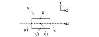
- FIG. 2 is a plan view illustrating the standard clamping locations R1 and R2 of the rectangular component P1.
- the outer shape of the body matches the part outer shape. Therefore, the body center data of the rectangular part P1 represents the position of the center C1 of the part outline shown.
- the standard angle data of the rectangular part P1 is defined as a direction angle of 0 °. Accordingly, when the auxiliary line AL1 parallel to the X axis is drawn through the center C1 of the component outer shape, the intersection between the auxiliary line AL1 and the component outer surface becomes the standard clamping locations R1 and R2.
- the standard clamping locations R1 and R2 are located on the side surface of the midpoint of the short side of the rectangular component P1. If the standard angle data of the rectangular part P1 is defined as a direction angle of 90 °, the standard clamping locations U1 and U2 are located on the side surface of the midpoint of the long side of the rectangular part P1. Thus, if it clamps from both sides so that the center C1 of the component P1 may be pinched
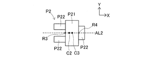
- FIG. 3 is a plan view illustrating the standard clamping locations R3 and R4 of the part P2 where the terminal portion P22 protrudes from the body P21.
- the component P2 is formed by projecting three low-profile terminal portions P22 from a tall body P21 into an asymmetric shape. Therefore, in the component P2, the outer shape of the body P21 does not match the component outer shape.
- part which protrudes from the body P21 is not limited to the terminal part P22.
- the center C2 of the part outline of the part P2 is used for the purpose of specifying the mounting coordinate position.
- the body center data of the part P2 represents the position of the center C3 of the rectangular body P21.
- the standard angle data of the part P2 is defined as a direction angle of 0 °. Therefore, when the auxiliary line AL2 parallel to the X-axis is drawn through the center C3 of the body P21, the intersections of the auxiliary line AL2 and the body outer surface become standard clamping locations R3 and R4.
- the control unit of the component mounting machine grasps the deviation amount of the center C3 of the body P21 with respect to the center C2 of the component outer shape, that is, the center deviation amount, and reflects it in the component mounting operation.
- the computer usually determines the sampling conditions at the component supply position so that the pair of claw portions 51 and 52 of the mechanical chuck nozzle 1 clamp the standard clamping locations R1 to R4 of the components P1 and P2. However, when the pair of claw portions 51 and 52 sandwich the standard sandwiching locations R1 to R4 of the parts P1 and P2, it is an exception when they interfere with the mounted parts. In this case, the computer determines the sampling condition at the component supply position so as to avoid interference by changing the clamping location of the components P1 and P2 from the standard clamping locations R1 to R4.
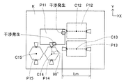
- FIG. 4 is a plan view of the substrate K for illustrating the case where the pair of claw portions 51 and 52 of the mechanical chuck nozzle 1 interfere with a mounted component when the standard clamping portion of the component is clamped.
- FIG. 5 is a plan view of the substrate K illustrating the function of changing the part holding position from the standard holding position to avoid interference.
- the large component P11, the two rectangular components P12, P13, and the two hexagonal components P14, P15 are mounted on the board K in the order described.
- the two rectangular parts P12 and P13 and the two hexagonal parts P14 and P15 are mounted using the mechanical chuck nozzle 1.
- the body center data of the rectangular parts P12 and P13 represents the centers C12 and C13 of the part outline. Further, the standard angle data of the rectangular parts P12 and P13 is defined as a direction angle of 0 °. According to this rule, the standard clamping locations of the rectangular parts P12 and P13 are the sides of the two short sides. Further, the body center data of the hexagonal parts P14 and P15 represents the centers C14 and C15 of the part outline. Further, the standard angle data of the hexagonal parts P14 and P15 is defined as a direction angle of 90 °. According to this rule, the standard clamping locations of the hexagonal parts P14 and P15 are two side surfaces parallel to the X axis.
- the computer can grasp the component arrangement status shown in FIG. 4 based on the shape of each component P11 to P15, the dimensions of each component, and the mounting coordinate position on the substrate K.
- the large component P11 to be mounted first is indicated by a solid line as the mounted component P11
- the components P12 to P15 to be mounted second and subsequent are indicated by a broken line.
- two rectangular parts P12 and P13 are arranged side by side on the right side of the large part P11 in the drawing, and two hexagonal parts P14 and P15 are arranged on the lower side of the large part P11 in the figure. It is arranged with.
- the computer determines the positions of the pair of claw portions 51 and 52 (standard) when opening the parts P12 to P15 based on the body center data and the standard angle data of the parts P12 to P15 to be mounted after the second. And the coordinate range of the opening operation can be obtained.
- the positions of the pair of claw portions 51 and 52 and the coordinate range of the opening operation are shown by a pair of isosceles trapezoids facing each other. The positional relationship between the pair of isosceles trapezoids corresponds to the open dimension Lm shown in FIG.
- the computer targets the rectangular part P12 and the hexagonal part P14 in which interference occurs, and changes the clamping part from the standard clamping part to avoid the interference as shown in FIG.
- the computer determines that the standard clamping location is clamped in the rectangular part P13 and the hexagonal part P15 in which no interference occurs.
- the clamping center shift data is data indicating the shift amount of the clamping center shifted from the center of the body of the part.
- the sandwiching center shift data can be expressed using the shift amount in the X-axis direction and the shift amount in the Y-axis direction, and is not limited to this. In the case of non-zero data in which at least one of the shift amounts in the X-axis direction and the Y-axis direction is not zero, the sandwiching center shifts from the center of the body.
- the angle data is data indicating a directional angle at which the clamping portion is located with reference to the clamping center.
- the computer sets the clamping center shift data to zero data. That is, the computer sets both the amounts of deviation in the X-axis direction and the Y-axis direction to zero. In addition, the computer matches the angle data to the standard angle data. As can be seen from the above description, the computer corresponds to the holding portion determining means of the present invention.
- the computer sets the shift amount in the X-axis direction of the sandwiching center shift data regarding the rectangular part P12 to zero, and sets the shift amount Y1 in the Y-axis direction.
- the clamping center W12 shifts by a shift amount Y1 in the Y-axis direction from the center C12 of the external shape of the rectangular part P12.
- the computer matches the angle data regarding the rectangular part P12 with the standard angle data. Then, the position of the pair of claw portions 51 and 52 that sandwich the rectangular part P12 and the coordinate range of the opening operation move by Y1 in the Y-axis direction, and interference is avoided.
- the above-described sandwiching center shift data is applied to the sampling conditions at the component supply position. As a result, the relative positional relationship between the rectangular component P12 and the pair of claw portions 51 and 52 at the component supply position changes from the normal amount by the shift amount Y1, and the sampling operation is performed.
- the computer may change the sandwiching center shift data regarding the rectangular part P12 to zero data and change the angle data to a direction angle of 90 °.
- claw parts 51 and 52 moves to the side surface of the two long sides of the rectangular component P12.
- the rectangular component P13 is not yet mounted
- the computer sets the sandwiching center shift data related to the hexagonal part P14 as zero data, and makes the angle angle of the angle data 150 ° different from the direction angle 90 ° of the reference angle data.
- claw parts 51 and 52 which clamps the hexagonal component P14 moves to the side surface adjacent to counterclockwise from the side surface of a standard clamping location, and interference is avoided.
- the component mounting method includes a pair of claw portions 51 and 52 that clamp and collect a component at a component supply position, open the component on the substrate, and mount the component at a predetermined position on the substrate.
- a component mounting method using the mechanical chuck nozzle 1 mounted so as to be movable between the component supply position and the substrate, and the components P12 to P15 are attached to the mounted component P11 already mounted on the substrate K.
- the positions of the parts P12 to P15 sandwiched between the pair of claws 51 and 52 are determined so that the positions of the pair of claws 51 and 52 when they are opened and the opening operation do not interfere with each other.
- the clamping positions of the parts P12 to P15 sandwiched between the pair of claws 51 and 52 are temporarily held as standard. Can be defined as a place. Then, the position of the pair of claws 51 and 52 when the components P12 to P15 are opened on the board K and the coordinate range of the opening operation can be obtained, and it can be determined whether or not they interfere with the mounted component P11. If there is no interference as a result of the determination, the standard clamping location can be adopted, and if there is interference, the final clamping location can be determined so as not to interfere by changing the standard clamping location. As a result, the components P12 to P15 can be mounted while avoiding interference.
- the component defines a standard clamping location that is normally clamped between the pair of claw portions 51 and 52, and the pair of claw portions 51 and 52 is the standard of the components P12 and P14.
- the clamping part is clamped, when at least one of the positions of the pair of claws 51 and 52 and the opening operation interferes with the mounted part P11, the clamping part of the parts P12 and P14 is changed from the standard clamping part to cause interference. To avoid.
- a standard pinching point that can stabilize the sampling operation and the mounting operation is usually used, and the pinching point is changed from the standard pinching point only when interference occurs. Therefore, it is possible to reliably avoid interference while maintaining the stability of the sampling operation and the mounting operation.
- the standard clamping locations of the components P12 to P15 are determined on the side surfaces of the bodies of the components P12 to P15, and the center of the body (the centers of the component outlines C12 to C15)
- the standard angle data indicating the direction angle at which the standard clamping location is located with respect to the center of the body, and the clamping location of the parts P12 and P14 is the center of the body of the part P12 (part outline) Parts P13 and P15, which are defined using sandwiching center shift data indicating the shift amount of the sandwiching center W12 shifted from the center C12) and angle data indicating the direction angle where the sandwiching position is located with reference to the sandwiching center.
- the clamping center deviation data is set to zero data
- the angle data is set to the standard angle data.
- the clamping center change in which the clamping center deviation data is non-zero data and the angle change in which the angle data is different from the standard angle data Make at least one change.
- the combination of the component transfer device including the mechanical chuck nozzle 1 and the computer corresponding to the sandwiching location determining means constitutes the component mounting device according to the embodiment of the present invention.
- the component mounting apparatus of embodiment can implement the component mounting method of 1st Embodiment. Therefore, the component mounting apparatus according to the embodiment has the same effect as the component mounting method according to the first embodiment.
- the configuration of the component mounter and the mechanical chuck nozzle 1 used in the component mounting method of the second embodiment is the same as that of the first embodiment.
- the first method is compared with the second method to avoid interference. To decide.
- the first method is a method of changing the part clamping part described in the first embodiment from the standard clamping part.
- the second method is a method of changing the mounting order of a plurality of components.
- FIG. 6 is a diagram conceptually showing a part of the data structure of production job data.
- Production job data is based on substrate sequence data, and is configured by organically connecting a large number of data such as component shape data and nozzle specification data. These data may be held centrally in one place, or may be held dispersedly in a plurality of places and accessible to each other.
- the computer that performs the arithmetic processing of the component mounting method according to the second embodiment holds the production job data or can access the production job data.
- Substrate sequence data is produced for each type of substrate K to be produced.
- the board sequence data a plurality of types of parts to be mounted on the board K, a mounting order, a component supply position, and a mounting coordinate position are defined. Further, the sandwiching center shift data and the angle data necessary for determining the sampling conditions at the component supply position are also defined in the board sequence data.
- the substrate sequence data is finally determined by calculation processing performed by the computer for optimization and interference avoidance.
- Part shape data is linked corresponding to the type of parts in the board sequence data.
- the component shape data is unique to each component type and is shared by a plurality of board sequence data.
- the part shape data indicates the part name, the dimensions of each part, the nozzle used, and the like.
- a use nozzle is a nozzle used normally in order to extract
- body center data, standard angle data, and a center shift amount indicating a standard clamping portion are also defined in the part shape data.
- ⁇ Nozzle spec data is linked corresponding to the used nozzles in the part shape data.
- the nozzle specification data is unique to each type of nozzle, and is shared for a plurality of component shape data.
- the nozzle specification data indicates the nozzle name and the dimensions of each part.
- the nozzle specification data of the mechanical chuck nozzle 1 indicates an opening dimension Lm when the pair of claw portions 51 and 52 are opened, a minimum separation dimension when the pair is closed, and the like. Further, for example, the size of the suction opening is shown in the nozzle specification data of the suction nozzle.
- FIG. 7 is a diagram showing a calculation processing flow for optimizing the substrate sequence data and avoiding interference.
- the computer creates substrate sequence data SD0 by normal production optimization.
- the normal production optimization means minimizing the mounting cycle time without considering interference with the mounted parts of the mechanical chuck nozzle 1.
- the mounting cycle time is a time that is expected to be necessary for mounting all the plurality of components on the board.
- the mounting cycle time is a total value such as the replacement time of the suction nozzle and the mechanical chuck nozzle 1 in the mounting head 9 of the component transfer apparatus, the component sampling time of each nozzle, the movement time, and the component mounting time. Therefore, the mounting cycle time depends on the mounting order of a plurality of components, the arrangement order of the types of components at a plurality of component supply positions of the component supply apparatus, and the like. Normal production optimization can be carried out by applying various known techniques.
- step S2 the computer determines whether interference with the mounted component of the mechanical chuck nozzle 1 occurs when the component is mounted based on the substrate sequence data SD0. If no interference occurs, the computer proceeds to step S3, decides to adopt the substrate sequence data SD0, and ends the calculation processing flow. If interference occurs, the computer proceeds to step S4, and determines whether the interference can be avoided by changing the mounting order. The computer proceeds to step S5 if the interference can be avoided, and proceeds to step S7 if the interference cannot be avoided.
- step S5 the computer changes the mounting order from the board sequence data SD0 to avoid interference, performs optimization again, and then creates board sequence data SD2. In the optimization again, it is investigated whether or not a useless portion is generated in the movement path of the mounting head 9 as a result of changing the mounting order. If a useless part has occurred, the order of component mounting and the order of component types are further changed within a range where interference can be avoided.
- the calculation process in step S5 corresponds to the second method of the present invention.
- the computer estimates the second mounting cycle time T2 when the component is mounted based on the board sequence data SD2, and then proceeds to step S7.
- step S7 the computer determines whether or not interference can be avoided by changing the sandwiching location.
- the computer proceeds to step S8 if the interference can be avoided, and proceeds to step S10 if the interference cannot be avoided.
- step S8 the computer changes the holding position from the substrate sequence data SD0 to avoid interference, performs optimization again, and creates the substrate sequence data SD1.
- the method for changing the clamping portion has been described in the first embodiment. Further, in the re-optimization, the waste of the movement path of the mounting head 9 and the waste of the operation of the mechanical chuck nozzle 1 are eliminated after changing the clamping portion.
- the calculation process in step S8 corresponds to the first method of the present invention.
- the computer estimates the first mounting cycle time T1 when the component is mounted based on the board sequence data SD1, and then proceeds to step S10.
- step S10 the computer investigates the presence / absence of the first mounting cycle time T1 and the second mounting cycle time T2.
- the computer proceeds to step S11, decides to adopt the substrate sequence data SD1, and ends the calculation processing flow.
- the computer proceeds to step S12, decides to adopt the substrate sequence data SD2, and ends the calculation processing flow. If both the first mounting cycle time T1 and the second mounting cycle time T2 are present, the computer proceeds to step S13 and compares the first mounting cycle time T1 and the second mounting cycle time T2 with each other. If the first mounting cycle time T1 is smaller, the computer proceeds to step S11, otherwise proceeds to step S12. As a result, the computer can decide to adopt the board sequence data on the side with the shorter mounting cycle time.
- step S14 If neither the first mounting cycle time T1 nor the second mounting cycle time T2 is present, the computer proceeds to step S14, performs an abnormal process, and ends the arithmetic processing flow.
- the abnormal process for example, notification is made that interference cannot be avoided. In this case, interference cannot be avoided by changing the mounting order and changing the clamping part. Accordingly, it is necessary to take measures such as using a special mechanical chuck nozzle or changing the design of the component arrangement on the substrate.
- the standard clamping location of the component is defined as body center data and standard angle data in the component shape data holding various quantities related to the shape of the component.
- the actual clamping position of the parts is defined as clamping center shift data and angle data in the board sequence data that defines the mounting order and mounting coordinate positions of a plurality of parts to be mounted on the board.
- the standard clamping location is defined in the part shape data unique to each type of component, and the actual clamping location that can change depending on the type of board is individually defined in each board sequence data.
- the actual clamping location is defined in the part shape data. Therefore, it is necessary to produce new part shape data every time the actual clamping position changes. For this reason, a plurality of part shape data are mixed in spite of being one kind of part, and the management of data is complicated and an error tends to occur.
- the first mounting for avoiding the interference by the first method (step S8) of changing the clamping position of the component from the standard clamping position
- the second mounting cycle time T2 in the case of avoiding interference by the second method (step S5) of estimating the cycle time T1 and changing the mounting order of a plurality of components defined in the board sequence data, and the first mounting Of the cycle time T1 and the second mounting cycle time T2, the method on the short side is employed.
- the clamping center shift data may be left as zero data, and the clamping position may be changed by another method in which the mechanical chuck nozzle 1 is replaced with a dedicated mechanical chuck nozzle.
- the dedicated mechanical chuck nozzle is obtained by translating the arrangement position of the pair of claw parts 51 and 52 with respect to the main body part 2 of the mechanical chuck nozzle 1 by a deviation amount Y1 (moving in the front and back direction in FIG. 1).
- the mechanical chuck nozzle 1 described in the first embodiment is an example of a component mounting tool that clamps a component with a plurality of claws, and a component mounting tool having a different configuration may be used.
- Various other modifications and applications of the present invention are possible.
Landscapes
- Engineering & Computer Science (AREA)
- Manufacturing & Machinery (AREA)
- Microelectronics & Electronic Packaging (AREA)
- Operations Research (AREA)
- Supply And Installment Of Electrical Components (AREA)
Abstract
Description
3:エア駆動部 4:挟持機構部 51、52:爪部
9:装着ヘッド
Lm:開放寸法 K:基板 P1:長方形部品
P2:部品 P21:ボディ P22:端子部
P11:大型部品(装着済み部品)
P12、P13:長方形部品 P14、P15:六角形部品
C1、C2、C12~C15:部品外形の中心
C3:部品のボディの中心
R1~R4:標準挟持箇所
W12:挟持中心 Y1:偏移量
Claims (6)
- 部品供給位置で部品を挟持して採取し、基板上で前記部品を開放して前記基板の所定位置に前記部品を装着する複数の爪部を有して、前記部品供給位置と前記基板との間を移動可能に装架された部品装着具を用いる部品装着方法であって、
既に前記基板に装着された装着済み部品に対して、前記部品を開放するときの前記複数の爪部の位置および開放動作が干渉しないように、前記複数の爪部が挟持する前記部品の挟持箇所を決定する部品装着方法。 - 前記部品は、前記複数の爪部に通常挟持される標準挟持箇所が規定されており、
前記複数の爪部が前記部品の前記標準挟持箇所を挟持すると、前記装着済み部品に対して前記複数の爪部の位置および開放動作の少なくとも一方が干渉するときに、前記部品の挟持箇所を前記標準挟持箇所から変更して干渉を回避する請求項1に記載の部品装着方法。 - 前記部品の標準挟持箇所は、前記部品のボディの側面に規定されており、かつ、前記ボディの中心を示すボディ中心データ、および前記ボディの中心を基準として前記標準挟持箇所が位置する方向角度を示す標準角度データを用いて規定され、
前記部品の挟持箇所は、前記部品のボディの中心から偏移した挟持中心の偏移量を示す挟持中心偏移データ、および前記挟持中心を基準として前記挟持箇所が位置する方向角度を示す角度データを用いて規定され、
前記部品の挟持箇所を前記標準挟持箇所から変更しないときに、前記挟持中心偏移データをゼロデータとし、かつ、前記角度データを前記標準角度データに一致させ、
前記部品の挟持箇所を前記標準挟持箇所から変更するときに、前記挟持中心偏移データを非ゼロデータとする挟持中心変更、および、前記角度データを前記標準角度データと異なるデータにする角度変更の少なくとも一方の変更を行う請求項2に記載の部品装着方法。 - 前記部品の標準挟持箇所は、前記部品の形状に関する諸量を保持する部品シェイプデータに規定され、
前記部品の挟持箇所は、前記基板に装着する複数の部品の装着順序および装着座標位置を定めた基板シーケンスデータに規定される請求項2または3に記載の部品装着方法。 - 前記基板に前記複数の部品を装着する所要時間を装着サイクルタイムとし、
前記複数の爪部が前記部品の前記標準挟持箇所を挟持すると、前記装着済み部品に対して前記複数の爪部の位置および開放動作の少なくとも一方が干渉するときに、
前記部品の挟持箇所を前記標準挟持箇所から変更する第1方法により前記干渉を回避する場合の第1装着サイクルタイムを推定し、
前記基板シーケンスデータに定められた前記複数の部品の装着順序を変更する第2方法により前記干渉を回避する場合の第2装着サイクルタイムを推定し、
前記第1装着サイクルタイムおよび前記第2装着サイクルタイムのうち短時間の側の方法を採用する請求項4に記載の部品装着方法。 - 部品供給位置で部品を挟持して採取し、基板上で前記部品を開放して前記基板の所定位置に前記部品を装着する複数の爪部を有して、前記部品供給位置と前記基板との間を移動可能に装架された部品装着具を備える部品装着装置であって、
既に前記基板に装着された装着済み部品に対して、前記部品を開放するときの前記複数の爪部の位置および開放動作が干渉しないように、前記複数の爪部が挟持する前記部品の挟持箇所を決定する挟持箇所決定手段をさらに備える部品装着装置。
Priority Applications (5)
| Application Number | Priority Date | Filing Date | Title |
|---|---|---|---|
| JP2016537704A JP6426742B2 (ja) | 2014-08-01 | 2014-08-01 | 部品装着方法および部品装着装置 |
| EP14898630.0A EP3177128B1 (en) | 2014-08-01 | 2014-08-01 | Component mounting method and component mounting device |
| PCT/JP2014/070345 WO2016017029A1 (ja) | 2014-08-01 | 2014-08-01 | 部品装着方法および部品装着装置 |
| CN201480080744.7A CN106664822B (zh) | 2014-08-01 | 2014-08-01 | 元件装配方法及元件装配装置 |
| US15/500,708 US10477750B2 (en) | 2014-08-01 | 2014-08-01 | Component mounting method and component mounting device |
Applications Claiming Priority (1)
| Application Number | Priority Date | Filing Date | Title |
|---|---|---|---|
| PCT/JP2014/070345 WO2016017029A1 (ja) | 2014-08-01 | 2014-08-01 | 部品装着方法および部品装着装置 |
Publications (1)
| Publication Number | Publication Date |
|---|---|
| WO2016017029A1 true WO2016017029A1 (ja) | 2016-02-04 |
Family
ID=55216964
Family Applications (1)
| Application Number | Title | Priority Date | Filing Date |
|---|---|---|---|
| PCT/JP2014/070345 WO2016017029A1 (ja) | 2014-08-01 | 2014-08-01 | 部品装着方法および部品装着装置 |
Country Status (5)
| Country | Link |
|---|---|
| US (1) | US10477750B2 (ja) |
| EP (1) | EP3177128B1 (ja) |
| JP (1) | JP6426742B2 (ja) |
| CN (1) | CN106664822B (ja) |
| WO (1) | WO2016017029A1 (ja) |
Cited By (2)
| Publication number | Priority date | Publication date | Assignee | Title |
|---|---|---|---|---|
| WO2018051451A1 (ja) * | 2016-09-15 | 2018-03-22 | 富士機械製造株式会社 | 電子部品クランプ装置用のテンプレート及びそれを用いた確認方法 |
| WO2019077671A1 (ja) * | 2017-10-17 | 2019-04-25 | 株式会社Fuji | 装着ヘッドおよび部品装着機 |
Families Citing this family (4)
| Publication number | Priority date | Publication date | Assignee | Title |
|---|---|---|---|---|
| US10939598B2 (en) * | 2015-06-10 | 2021-03-02 | Fuji Corporation | Control device and control method for reducing a position error of a component mounting machine |
| WO2019058470A1 (ja) * | 2017-09-21 | 2019-03-28 | 株式会社Fuji | 装着部品保持用チャックおよび部品装着機 |
| WO2019097671A1 (ja) * | 2017-11-17 | 2019-05-23 | 株式会社Fuji | 演算装置 |
| US11846806B2 (en) * | 2020-09-09 | 2023-12-19 | Ciena Corporation | Stress compensating pick-up tool |
Citations (4)
| Publication number | Priority date | Publication date | Assignee | Title |
|---|---|---|---|---|
| JPH02219179A (ja) * | 1989-02-21 | 1990-08-31 | Hitachi Ltd | 対話型部品配置評価方法とその装置 |
| JPH069888U (ja) * | 1991-12-25 | 1994-02-08 | 富士通テン株式会社 | チャック装置 |
| JP2774841B2 (ja) * | 1989-11-28 | 1998-07-09 | パイオニア株式会社 | 画像認識部品装着装置における部品把持位置設定方法 |
| JP2007194673A (ja) * | 1999-12-07 | 2007-08-02 | Matsushita Electric Ind Co Ltd | 部品実装方法、その装置、及び記録媒体 |
Family Cites Families (18)
| Publication number | Priority date | Publication date | Assignee | Title |
|---|---|---|---|---|
| US4146924A (en) * | 1975-09-22 | 1979-03-27 | Board Of Regents For Education Of The State Of Rhode Island | System for visually determining position in space and/or orientation in space and apparatus employing same |
| DE3044860C2 (de) | 1980-11-28 | 1987-04-09 | Blaupunkt-Werke Gmbh, 3200 Hildesheim | Verfahren und Vorrichtung zur Bestückung gedruckter Schaltungen |
| US4412293A (en) * | 1981-03-30 | 1983-10-25 | Kelley Robert B | Robot system which acquires cylindrical workpieces from bins |
| US4598456A (en) * | 1984-10-19 | 1986-07-08 | Westinghouse Electric Corp. | Assembly system for electronic circuit boards |
| US4663821A (en) * | 1985-12-16 | 1987-05-12 | Zenith Electronics Corporation | Component handling apparatus |
| JP2541220B2 (ja) * | 1987-05-19 | 1996-10-09 | ソニー株式会社 | 電子部品装着装置 |
| JP3041404B2 (ja) * | 1990-11-16 | 2000-05-15 | セイコーインスツルメンツ株式会社 | オートサンプリング機構 |
| US5903663A (en) * | 1995-02-15 | 1999-05-11 | Tiede GmbH & Co.Risprufanlagen | Automatic error recognition apparatus |
| JP3504394B2 (ja) * | 1995-09-08 | 2004-03-08 | 松下電器産業株式会社 | 部品配列のデータ作成方法 |
| JP4037593B2 (ja) | 1999-12-07 | 2008-01-23 | 松下電器産業株式会社 | 部品実装方法及びその装置 |
| JP2002219179A (ja) * | 2001-01-24 | 2002-08-06 | Toshinobu Iwakura | 管の中にワイヤーを挿入して剛性を高めた医療用の吸引カテーテルと、そのワイヤーの装着装置 |
| JP2002335097A (ja) | 2001-05-11 | 2002-11-22 | Matsushita Electric Ind Co Ltd | 部品実装方法および装置 |
| JP3999509B2 (ja) | 2001-12-11 | 2007-10-31 | シチズンホールディングス株式会社 | 電子部品の組付装置及び組付方法 |
| JP2004221167A (ja) | 2003-01-10 | 2004-08-05 | Matsushita Electric Ind Co Ltd | 電子部品実装方法及び実装装置 |
| JP4896757B2 (ja) | 2007-02-09 | 2012-03-14 | ヤマハ発動機株式会社 | 表面実装機 |
| NL2001790C2 (nl) * | 2008-07-11 | 2010-01-12 | Fico Bv | Inrichting en werkwijze voor het zagen van elektronische componenten. |
| CH705802B1 (de) * | 2011-11-25 | 2016-04-15 | Esec Ag | Einrichtung für die Montage von Halbleiterchips. |
| KR101866179B1 (ko) | 2012-06-06 | 2018-06-11 | 가부시키가이샤 후지 | 부품 삽입 조립 장치 |
-
2014
- 2014-08-01 US US15/500,708 patent/US10477750B2/en active Active
- 2014-08-01 CN CN201480080744.7A patent/CN106664822B/zh active Active
- 2014-08-01 WO PCT/JP2014/070345 patent/WO2016017029A1/ja active Application Filing
- 2014-08-01 JP JP2016537704A patent/JP6426742B2/ja active Active
- 2014-08-01 EP EP14898630.0A patent/EP3177128B1/en active Active
Patent Citations (4)
| Publication number | Priority date | Publication date | Assignee | Title |
|---|---|---|---|---|
| JPH02219179A (ja) * | 1989-02-21 | 1990-08-31 | Hitachi Ltd | 対話型部品配置評価方法とその装置 |
| JP2774841B2 (ja) * | 1989-11-28 | 1998-07-09 | パイオニア株式会社 | 画像認識部品装着装置における部品把持位置設定方法 |
| JPH069888U (ja) * | 1991-12-25 | 1994-02-08 | 富士通テン株式会社 | チャック装置 |
| JP2007194673A (ja) * | 1999-12-07 | 2007-08-02 | Matsushita Electric Ind Co Ltd | 部品実装方法、その装置、及び記録媒体 |
Cited By (7)
| Publication number | Priority date | Publication date | Assignee | Title |
|---|---|---|---|---|
| WO2018051451A1 (ja) * | 2016-09-15 | 2018-03-22 | 富士機械製造株式会社 | 電子部品クランプ装置用のテンプレート及びそれを用いた確認方法 |
| CN109716879A (zh) * | 2016-09-15 | 2019-05-03 | 株式会社富士 | 电子元件夹持装置用的模板及使用了该模板的确认方法 |
| JPWO2018051451A1 (ja) * | 2016-09-15 | 2019-06-24 | 株式会社Fuji | 電子部品クランプ装置用のテンプレート及びそれを用いた確認方法 |
| EP3515164A4 (en) * | 2016-09-15 | 2019-09-04 | Fuji Corporation | TEMPLATE FOR ELECTRONIC COMPONENT TIGHTENING DEVICE AND VERIFICATION METHOD USING THE SAME |
| US10645851B2 (en) * | 2016-09-15 | 2020-05-05 | Fuji Corporation | Template for electronic component clamping device and confirmation method using same |
| CN109716879B (zh) * | 2016-09-15 | 2020-09-25 | 株式会社富士 | 电子元件夹持装置用的模板及使用了该模板的确认方法 |
| WO2019077671A1 (ja) * | 2017-10-17 | 2019-04-25 | 株式会社Fuji | 装着ヘッドおよび部品装着機 |
Also Published As
| Publication number | Publication date |
|---|---|
| CN106664822A (zh) | 2017-05-10 |
| EP3177128B1 (en) | 2020-10-14 |
| JPWO2016017029A1 (ja) | 2017-05-18 |
| US20170223881A1 (en) | 2017-08-03 |
| JP6426742B2 (ja) | 2018-11-21 |
| EP3177128A4 (en) | 2017-08-09 |
| EP3177128A1 (en) | 2017-06-07 |
| US10477750B2 (en) | 2019-11-12 |
| CN106664822B (zh) | 2019-07-09 |
Similar Documents
| Publication | Publication Date | Title |
|---|---|---|
| WO2016017029A1 (ja) | 部品装着方法および部品装着装置 | |
| JP6019409B2 (ja) | 電子部品実装装置及び電子部品実装方法 | |
| JP7068150B2 (ja) | ハンド、ロボットシステム及びワーク取り出し方法 | |
| US8794685B2 (en) | Robot hand and robot | |
| US8975552B2 (en) | Workpiece holder for holding a plurality of plate workpieces used for wire electric discharge machine | |
| TWI483335B (zh) | Grain bonding machine and bonding method | |
| JPWO2017145349A1 (ja) | ロボットアーム制御システム | |
| WO2014132292A1 (ja) | 吸着ノズルおよび表面実装機 | |
| JP4968282B2 (ja) | 部品実装装置 | |
| WO2015052753A1 (ja) | チャック装置及び部品装着機 | |
| JP2011177862A (ja) | 把持装置 | |
| JP6420533B2 (ja) | 作業装置 | |
| JP2009125867A (ja) | 産業用ロボットのハンド装置 | |
| JP7075498B2 (ja) | 作業機 | |
| JPWO2017125996A1 (ja) | 部品装着機 | |
| WO2015029142A1 (ja) | 組立システムおよび組立品の生産方法 | |
| JP5501917B2 (ja) | チャック装置 | |
| WO2018216147A1 (ja) | 部品把持具 | |
| WO2018189862A1 (ja) | 作業機 | |
| JP6022167B2 (ja) | 部品保持ヘッド、および、部品保持ヘッドを備えた装着作業機 | |
| JP5364179B2 (ja) | ワークの装着装置 | |
| JP5906901B2 (ja) | ロボットハンド、ロボット、及び取外方法 | |
| JP2009154253A (ja) | 産業用ロボットのハンド装置 | |
| JP2006140274A (ja) | ノズル交換ユニットにおけるノズル収納構造および表面実装機 | |
| JPWO2017056181A1 (ja) | 部品チャック装置および部品装着装置 |
Legal Events
| Date | Code | Title | Description |
|---|---|---|---|
| 121 | Ep: the epo has been informed by wipo that ep was designated in this application |
Ref document number: 14898630 Country of ref document: EP Kind code of ref document: A1 |
|
| ENP | Entry into the national phase |
Ref document number: 2016537704 Country of ref document: JP Kind code of ref document: A |
|
| REEP | Request for entry into the european phase |
Ref document number: 2014898630 Country of ref document: EP |
|
| WWE | Wipo information: entry into national phase |
Ref document number: 2014898630 Country of ref document: EP |
|
| WWE | Wipo information: entry into national phase |
Ref document number: 15500708 Country of ref document: US |
|
| NENP | Non-entry into the national phase |
Ref country code: DE |