WO2016013502A1 - 振れ止め装置 - Google Patents
振れ止め装置 Download PDFInfo
- Publication number
- WO2016013502A1 WO2016013502A1 PCT/JP2015/070487 JP2015070487W WO2016013502A1 WO 2016013502 A1 WO2016013502 A1 WO 2016013502A1 JP 2015070487 W JP2015070487 W JP 2015070487W WO 2016013502 A1 WO2016013502 A1 WO 2016013502A1
- Authority
- WO
- WIPO (PCT)
- Prior art keywords
- oil
- tube
- inner pipe
- pipe
- bar
- Prior art date
- Legal status (The legal status is an assumption and is not a legal conclusion. Google has not performed a legal analysis and makes no representation as to the accuracy of the status listed.)
- Ceased
Links
Images

Classifications
-
- B—PERFORMING OPERATIONS; TRANSPORTING
- B23—MACHINE TOOLS; METAL-WORKING NOT OTHERWISE PROVIDED FOR
- B23B—TURNING; BORING
- B23B13/00—Arrangements for automatically conveying or chucking or guiding stock
- B23B13/02—Arrangements for automatically conveying or chucking or guiding stock for turning-machines with a single working-spindle
-
- B—PERFORMING OPERATIONS; TRANSPORTING
- B23—MACHINE TOOLS; METAL-WORKING NOT OTHERWISE PROVIDED FOR
- B23B—TURNING; BORING
- B23B13/00—Arrangements for automatically conveying or chucking or guiding stock
- B23B13/08—Arrangements for reducing vibrations in feeding-passages or for damping noise
-
- B—PERFORMING OPERATIONS; TRANSPORTING
- B23—MACHINE TOOLS; METAL-WORKING NOT OTHERWISE PROVIDED FOR
- B23B—TURNING; BORING
- B23B13/00—Arrangements for automatically conveying or chucking or guiding stock
- B23B13/12—Accessories, e.g. stops, grippers
Definitions
- the present invention relates to a steady rest provided with a guide tube inserted in a spindle of a machine tool.
- the steady rest device has a chuck opening / closing pipe fitted in the main spindle of the automatic lathe and a cylindrical steady rest jig arranged inside the chuck opening / closing driving pipe.
- An outer diameter oil groove formed on the surface for sending the lubricating oil in the forward direction of the main shaft by rotation of the main shaft, and an inner diameter oil groove formed on the inner peripheral surface for sending the lubricating oil in the rear direction of the main shaft by rotating the main shaft A bar steadying device is known (for example, Patent Document 2).
- Japanese Patent No. 3713397 (refer to FIGS. 1 and 7 in particular)
- Japanese Patent Laid-Open No. 7-299604 (refer to FIGS. 1 and 2 in particular)
- the present invention solves the problems of the prior art as described above, that is, the object of the present invention is to prevent the oil in the guide tube from being collected without splashing with a simple structure. Is to provide a device.
- the invention according to claim 1 includes a guide tube made of a material into which a material to be processed by a machine tool is inserted, oil flows through the guide tube, passes through the material through the guide tube, and passes to the machine tool.
- the guide tube includes an outer tube that extends along the axial direction, and an inner tube that is supported in the outer tube via a predetermined gap. A material is inserted into the inner pipe, an oil return path is formed by a gap between the outer pipe and the inner pipe, and oil introduced into the inner pipe is discharged through the oil return path.
- the invention according to claim 2 provides an inner tube support for supporting the inner tube with respect to the outer tube in the gap between the outer tube and the inner tube in addition to the configuration of the steady rest device according to claim 1.
- the above-described problems are further solved by disposing a body and providing an oil circulation part for allowing oil to flow freely in the inner tube support.
- the oil in the inner pipe is guided to the end of the inner pipe to the oil return path side.
- the invention according to claim 4 is described above by providing the guide portion with a funnel-shaped tapered surface for guiding the passage of the material in addition to the configuration of the steady rest device according to claim 3. The problem is further solved.
- the guide tube is inserted into the main shaft of the machine tool.
- the steady rest device of the present invention includes a material guide tube through which a material to be processed by a machine tool is inserted, oil is circulated in the guide tube, and the material passes through the guide tube and is supplied to the machine tool. Not only can the vibration of the material during rotation be suppressed, but also the following specific effects can be achieved.
- the oil return path is formed by the gap between the outer pipe and the inner pipe, and the oil introduced into the inner pipe is discharged through the oil return path. Oil can be collected smoothly by preventing the oil from splashing.
- the inner pipe is stabilized with respect to the outer pipe without obstructing the flow of oil in the oil return path. Since it is supported, the vibration of the inner tube can be prevented and the vibration of the material can be prevented more reliably.
- the oil that has flowed to the end side in the inner tube is smoothly transferred to the oil return path. I can guide you.
- the material tip is guided and guided by the tapered surface when the material tip passes. Can be smoothly supplied.
- the outer tube of the guide tube inserted into the spindle of the machine tool Since the oil return path is formed by the gap with the inner pipe, the oil can be smoothly recovered by preventing the oil from scattering in the main shaft.
- FIG. 1 is a schematic cross-sectional view of a main spindle portion of a machine tool provided with a bar steadying device according to an embodiment of the present invention.
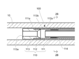
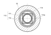
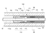
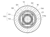
- FIG. 2B-2B sectional view of FIG. 2A. The figure which showed the bar in FIG. 2A. The figure which showed the bar in FIG. 2B.
- the present invention includes a material guide tube into which a material to be processed by a machine tool is inserted, oil is circulated in the guide tube, and the material passes through the guide tube and is supplied to the machine tool.
- the guide tube includes an outer tube extending in the axial direction and an inner tube supported in the outer tube via a predetermined gap, and a material is inserted into the inner tube.
- the oil recirculation path is formed by the gap between the outer pipe and the inner pipe, and the oil introduced into the inner pipe is discharged through the oil recirculation path to prevent the oil from scattering. Any specific embodiment may be used as long as it can be recovered smoothly.
- the oil flowing toward the main shaft front end side in the inner pipe inner peripheral oil flow path may be transferred to the inner pipe outer peripheral side oil flow path at the front end portion and flowing back to the main shaft rear end side.
- the guide tube material may be any material as long as it suppresses the vibration of the rotating material.
- the machine tool M has a main shaft 10 and a bar steadying device 100 as a steadying device on a base 20.
- the main shaft 10 is rotatably supported by the main shaft base 11, and a bar W (see FIGS. 3A and 3B), which is a material, is inserted and supplied from the rear side through the bar steadying device 100.
- the bar W is gripped by the chuck 10a.
- the main shaft 10 is rotationally driven by a built-in motor 14 provided between the main shaft base 11 and the main shaft 10.
- the headstock 11 is slidably supported on a main spindle Z-axis rail 12 provided on the base 20. Between the headstock 11 and the base 20, a linear motor including a mover 13 on the side of the mainhead 11 and a stator 21 on the side of the base 20 is provided.
- the headstock 11 is configured to be position-controllable in the axial direction (Z-axis direction) by a linear motor serving as a driving device.
- the bar steadying device 100 has an inner insertion tube 110 with a distal end side inserted into the main shaft 10 as a guide tube.
- An intubation support 120 for supporting the rear end side of the intubation 110 is fixed on the base 20 via a bracket 22.
- the inner intubation 110 is fixed to the inner intubation support 120 by a fixing screw 124 via a support block 123.
- the inner intubation 110 includes an outer tube 111, an inner tube 112, and a cap 113.
- the outer tube 111 extends along the axial direction, and the rear end portion is inserted into the support block 123 and fixed integrally therewith.
- the inner tube 112 is inserted into the outer tube 111 via a predetermined gap.
- the rear end of the inner tube 112 is inserted into the support block 123 and protrudes rearward of the outer tube 111 within the support block 123 and is integrally fixed.
- the bar W is inserted into the inner pipe 112, and the inner diameter of the inner pipe 112 is formed to a size that supports the bar W in a rotatable manner in accordance with the diameter of the bar W.
- the distal end of the outer tube 111 protrudes forward from the distal end of the inner tube 112, and the cap 113 has the outer tube 111 such that a gap G ⁇ b> 3 is formed between the inner tube distal end portion 112 a of the inner tube 112 and the cap 113.
- the bar W protrudes from the inner tube 112, passes through the cap 113, and protrudes from the inner tube 110.
- the cap 113 is formed with a bar insertion hole 113a through which the bar W passes.
- the space in the inner pipe 112 communicates with the gap G1 between the inner pipe 112 and the outer pipe 111 through the gap G3.
- the support block 123 is provided with an oil injection part 121 (see FIG. 1) communicating with the inner pipe 112.
- oil injection part 121 see FIG. 1
- the supplied oil enters the inner pipe 112 from the inside of the inner pipe 112 using the gap G1 as an oil return path of the inner pipe. It can flow to the inner pipe outer peripheral side oil flow path C1 (gap G1) through the gap G3.
- the support block 123 is provided with an oil discharge part 122 (see FIG. 1) communicating with the inner pipe outer peripheral side oil flow path C1, and oil flowing through the inner pipe outer peripheral side oil flow path C1 is supplied from the oil discharge part 122. Discharged.
- a suction pump (not shown) may be connected to the oil discharge portion 122 so that the oil is discharged from the oil discharge portion 122 by the suction pump.
- a plurality of inner tube supports 114 that support the inner tube 112 with respect to the outer tube 111 are provided in the gap G1 between the outer tube 111 and the inner tube 112 in the axial direction.
- the inner tube support 114 stably supports the inner tube 112 with respect to the outer tube 111 while maintaining the gap G1.
- the inner tube supports 114 are arranged at equal intervals in the axial direction of the inner intubation 110.
- the inner pipe support 114 has an oil circulation notch 114a penetrating in the axial direction and is equally spaced in the circumferential direction as an example of an oil circulation section that allows oil to flow in the axial direction.
- an oil circulation section that allows oil to flow in the axial direction.
- Four are formed so that the outer periphery is notched. Due to the oil circulation notch 114a, the inner pipe support 114 does not hinder the flow of oil in the inner pipe outer peripheral oil passage C1.
- the oil can smoothly flow between the cap 113 side and the oil discharge portion 122 side via the oil circulation notch 114a in the inner pipe outer peripheral side oil passage C1.
- the oil circulation notch 114a is formed as the oil circulation portion, but the oil may be circulated by forming a hole penetrating in the axial direction.
- the oil circulation notch 114a is disposed on the inner peripheral side of the outer tube in the radial direction, but may be disposed on the outer peripheral side of the inner tube.
- This bar steadying device 100 is arranged so that the inner intubation 110 is inserted into the main shaft 10.
- the bar W is supplied from a material supply device (not shown), passes through the inner tube 112 and the cap 113, protrudes from the inner tube 110, is inserted into the chuck 10a of the main shaft 10, and protrudes a predetermined length from the chuck 10a. It is gripped by the chuck 10a.
- oil is supplied from the oil injection portion 121, so that the oil passes through the gap G2 between the inner tube 112 and the rod W and is oil on the inner circumferential side of the inner tube 112 and the cap 113.
- the flow path C 2 As the flow path C 2, it flows from the inner pipe inner peripheral oil flow path C 2 through the gap G 3 to the inner pipe outer peripheral oil flow path C 1 (gap G 1), and is discharged from the oil discharge portion 122.
- the inner pipe outer peripheral side oil flow path C1 and the inner pipe inner peripheral side oil flow path C2 are formed wider than the gap G4 between the bar insertion hole 113a and the bar W.
- a funnel-shaped tapered surface 113b that is gradually reduced in diameter toward the tip end side of the main shaft is continuously formed on the periphery of the bar insertion hole 113a of the cap 113.
- the taper surface 113b is expected to have an effect of easily changing the direction of the oil flowing in the inner pipe inner peripheral oil passage C2 toward the main shaft tip in the inner tube 110 toward the inner pipe outer peripheral oil passage C1. You can also.
- the oil in the inner pipe inner peripheral oil flow path C2 can be smoothly flowed into the inner pipe outer peripheral oil flow path C1 by the suction of oil by the suction pump.
- an inner tube 110 is supported by an outer tube 111 extending along the axial direction, and an inner tube supported within the outer tube 111 via a predetermined gap G1.
- Oil that is provided in the inner tube 112 is inserted into the inner tube 112, the rod W is inserted into the inner tube 112, and the outer tube 111 and the inner tube 112 form an oil passage C ⁇ b> 1 on the outer periphery of the inner tube 112. Is discharged through the inner pipe outer peripheral side oil flow path C1, so that the oil in the inner intubation 110 can be collected smoothly without scattering by a simple structure.
- an inner tube support 114 that supports the inner tube 112 with respect to the outer tube 111 is disposed in the gap G1 between the outer tube 111 and the inner tube 112, and oil flows through the inner tube support 114 in a freely flowing manner.
- the vibration of the inner pipe 112 is prevented without obstructing the oil flow in the inner pipe outer periphery side oil flow path C1, and the rod is surely secured.
- the vibration of the material W can be prevented.
- a cap 113 as a guide part for guiding the oil in the inner pipe 112 to the inner pipe outer peripheral side oil passage C1 side on the end side of the inner pipe 112, the oil flow is made smooth. Can do.
- the cap 113 with a funnel-shaped tapered surface 113b for guiding the passage of the bar W, the bar W is smoothly supplied when the new bar W is supplied to the chuck 10a at the tip of the spindle.
- the oil moves to the oil flow path C1 on the outer periphery side of the inner tube and can be smoothly turned back to the main shaft rear end side.
- the inner intubation tube 110 as the guide tube is inserted into the main shaft 10, but the inner intubation tube 110 may be disposed behind the main shaft 10 without being inserted into the main shaft 10. Further, it is desirable that the distal end of the inner intubation 110 is located as close to the chuck 10a of the main shaft 10 as possible.
- the space for maintenance can be formed between the support base 31 that supports the guide bush unit 30 and the main shaft 10. Must be configured.
- a minimum space in the Z-axis direction in which the main shaft 10 can move by a stroke required for machining is secured between the front end of the inner tube 110 and the chuck 10a side, and the rear end of the main shaft base 11 is supported.
- a predetermined space is provided between the tip of the block 123.
Landscapes
- Engineering & Computer Science (AREA)
- Mechanical Engineering (AREA)
- Turning (AREA)
Abstract
簡単な構造で案内管内のオイルを飛散させずに回収することができる振れ止め装置を提供すること。 工作機械で加工される材料(W)が挿通される材料(W)の案内管(110)を備え、この案内管(110)内にオイルが流通され、材料(W)を案内管(110)に貫通して工作機械に供給することによって、材料(W)の振れを抑制する振れ止め装置(100)において、案内管(110)が、軸線方向に沿って延設した外管(111)と、この外管(111)内に所定の間隙を介して支持される内管(112)とを備え、内管(112)内に材料(W)が挿入され、外管(111)と内管(112)との間隙によってオイル還流路(C1)が形成され、内管(112)内に導入されるオイルがオイル還流路(C1)を介して排出されるように構成されたことを特徴とする振れ止め装置(100)。
Description
本発明は、工作機械の主軸内に挿着した案内管を備えた振れ止め装置に関するものである。
従来、振れ止め装置として、棒材加工装置の中空管の中間部に設けられたオイル注入口からオイルが中空管の棒材通路の中に供給され、棒材が中空管の棒材通路の中に収容された状態で棒材が高速回転し、棒材の周面がオイルを連れ回って、棒材と棒材通路を構成する内壁面との間の隙間に油膜が形成され、棒材全体が中空管の中心軸線に向かって持ち上げられるものが知られている(例えば、特許文献1)。
また、振れ止め装置として、自動旋盤の主軸内に嵌装されたチャック開閉管およびチャック開閉駆動管の内部に配設された円筒状の振れ止め治具を有し、振れ止め治具が、外周面に形成されて主軸の回転によって潤滑油を主軸の前方方向に送る外径油溝と、内周面に形成されて主軸の回転によって潤滑油を主軸の後方方向に送る内径油溝とを備えている棒材振れ止め装置が知られている(例えば、特許文献2)。
しかしながら、上述した特許文献1に記載された棒材加工装置では、中空管の両端が開放された構造であったため、棒材と棒材通路の内壁面との間に満たされたオイルが中空管の両端からそのまま流出して先端側である主軸先端部で飛散してしまうという問題があった。
また、上述した特許文献2に記載された棒材振れ止め装置では、複数の円筒状の振れ止め治具のそれぞれに外径油溝および内径油溝を形成して潤滑油の流れを制御する構造であったため、構造が複雑になってしまうという問題があった。
また、上述した特許文献2に記載された棒材振れ止め装置では、複数の円筒状の振れ止め治具のそれぞれに外径油溝および内径油溝を形成して潤滑油の流れを制御する構造であったため、構造が複雑になってしまうという問題があった。
そこで、本発明は、前述したような従来技術の問題を解決するものであって、すなわち、本発明の目的は、簡単な構造で案内管内のオイルを飛散させずに回収することができる振れ止め装置を提供することである。
本請求項1に係る発明は、工作機械で加工される材料が挿通される材料の案内管を備え、該案内管内にオイルが流通され、前記材料を前記案内管に貫通して前記工作機械に供給することによって、前記材料の振れを抑制する振れ止め装置において、前記案内管が、軸線方向に沿って延設した外管と、該外管内に所定の間隙を介して支持される内管とを備え、前記内管内に材料が挿入され、前記外管と内管との間隙によってオイル還流路が形成され、前記内管内に導入されるオイルが前記オイル還流路を介して排出されるように構成されたことにより、前述した課題を解決するものである。
本請求項2に係る発明は、請求項1に記載された振れ止め装置の構成に加えて、前記外管と内管との間隙に、前記外管に対して内管を支持する内管支持体を配設し、該内管支持体にオイルを流通自在に流動させるオイル流通部を設けたことにより、前述した課題をさらに解決するものである。
本請求項3に係る発明は、請求項1または請求項2に記載された振れ止め装置の構成に加えて、前記内管の端部側に、前記内管内のオイルをオイル還流路側に案内する案内部を設けたことにより、前述した課題をさらに解決するものである。
本請求項4に係る発明は、請求項3に記載された振れ止め装置の構成に加えて、前記案内部に、前記材料の通過を案内する漏斗状のテーパ面を設けたことにより、前述した課題をさらに解決するものである。
本請求項5に係る発明は、請求項1乃至請求項4のいずれか1つに記載された振れ止め装置の構成に加えて、前記案内管が、前記工作機械の主軸内に挿入されて配置されたことにより、前述した課題をさらに解決するものである。
本発明の振れ止め装置は、工作機械で加工される材料が挿通される材料の案内管を備え、案内管内にオイルが流通され、材料を案内管に貫通して工作機械に供給することにより、回転時の材料の振れを抑制することができるばかりでなく、以下のような特有の効果を奏することができる。
本請求項1に係る発明の振れ止め装置によれば、外管と内管との間隙によってオイル還流路が形成され、内管内に導入されるオイルがオイル還流路を介して排出されるため、オイルの飛散を防止してオイルを円滑に回収できる。
本請求項2に係る発明の振れ止め装置によれば、請求項1に係る発明が奏する効果に加えて、オイル還流路におけるオイルの流れを妨げることなく外管に対して内管が安定して支持されるため、内管の振動を防止してより確実に材料の振動を防止することができる。
本請求項3に係る発明の振れ止め装置によれば、請求項1または請求項2に係る発明が奏する効果に加えて、内管内を端部側へ流れたオイルを、円滑にオイル還流路に案内することができる。
本請求項4に係る発明の振れ止め装置によれば、請求項3に係る発明が奏する効果に加えて、材料先端が通過する際に材料先端がテーパ面によって誘導案内されるため、材料の主軸への供給を円滑に行うことができる。
本請求項5に係る発明の振れ止め装置によれば、請求項1乃至請求項4のいずれかに係る発明が奏する効果に加えて、工作機械の主軸内に挿通された案内管の外管と内管との間隙によってオイル還流路が形成されるため、主軸内においてオイルの飛散を防止してオイルを円滑に回収できる。
本発明は、工作機械で加工される材料が挿通される材料の案内管を備え、この案内管内にオイルが流通され、材料を案内管に貫通して工作機械に供給することによって、材料の振れを抑制する振れ止め装置において、案内管が、軸線方向に沿って延設した外管と、この外管内に所定の間隙を介して支持される内管とを備え、内管内に材料が挿入され、外管と内管との間隙によってオイル還流路が形成され、内管内に導入されるオイルがオイル還流路を介して排出されるように構成されたことにより、オイルの飛散を防止してオイルを円滑に回収するものであれば、その具体的な実施態様は、如何なるものであっても構わない。
例えば、案内管内において内管内周側オイル流路を主軸先端部側へ流れるオイルが先端部分で内管外周側オイル流路へ移り主軸後端部側へ折り返すように流れる構成とすることができる。
案内管の材料は、回転する材料の振れを抑制するものであれば、如何なるものであってもよい。
案内管の材料は、回転する材料の振れを抑制するものであれば、如何なるものであってもよい。
図1に示すように、工作機械Mは、主軸10と、振れ止め装置としての棒材振れ止め装置100とを基台20上に有している。
主軸10は、主軸台11に回転駆動自在に支持され、後方側から棒材振れ止め装置100を介して材料である棒材W(図3A及び図3B参照)が挿入供給され、主軸先端部のチャック10aで棒材Wを把持する。
本実施例では、主軸10は、主軸台11と主軸10との間に設けられたビルトインモータ14によって回転駆動される。
主軸10は、主軸台11に回転駆動自在に支持され、後方側から棒材振れ止め装置100を介して材料である棒材W(図3A及び図3B参照)が挿入供給され、主軸先端部のチャック10aで棒材Wを把持する。
本実施例では、主軸10は、主軸台11と主軸10との間に設けられたビルトインモータ14によって回転駆動される。
主軸台11は、基台20に設けられた主軸Z軸レール12上にスライド自在に支持されている。主軸台11と基台20との間には、主軸台11側の可動子13と、基台20側の固定子21とを備えたリニアモータが設けられている。主軸台11は、駆動装置となるリニアモータによって軸線方向(Z軸方向)で位置制御可能に構成されている。
棒材振れ止め装置100は、先端側が主軸10内に挿着される内挿管110を案内管として有している。
基台20上には、内挿管110の後端側を支持する内挿管支持台120がブラケット22を介して固定されている。内挿管110は支持ブロック123を介して固定ネジ124によって内挿管支持台120に固定されている。
棒材振れ止め装置100は、先端側が主軸10内に挿着される内挿管110を案内管として有している。
基台20上には、内挿管110の後端側を支持する内挿管支持台120がブラケット22を介して固定されている。内挿管110は支持ブロック123を介して固定ネジ124によって内挿管支持台120に固定されている。
図2Aおよび図3Aに示すように、内挿管110は、外管111と、内管112と、キャップ113とを備えている。
外管111は、軸線方向に沿って延設され、後端部分が支持ブロック123に挿入されて一体的に固定されている。
内管112は、外管111内に所定の間隙を介して挿入されている。内管112の後端は、支持ブロック123内に挿入され、支持ブロック123内で外管111の後方に突出して一体的に固定されている。棒材Wは内管112内に挿入され、内管112の内径は棒材Wの径に応じて、棒材Wを回転自在に支持するようなサイズに形成されている。
外管111の先端は、内管112の先端より前方に突出しており、キャップ113は、内管112の内管先端部112aとキャップ113との間に間隙G3が形成されるように外管111の外管先端部111aに嵌着されている。棒材Wは内管112から突出し、キャップ113を通過して内挿管110から突出する。キャップ113には、棒材Wが通過する棒材挿通穴113aが形成されている。
外管111は、軸線方向に沿って延設され、後端部分が支持ブロック123に挿入されて一体的に固定されている。
内管112は、外管111内に所定の間隙を介して挿入されている。内管112の後端は、支持ブロック123内に挿入され、支持ブロック123内で外管111の後方に突出して一体的に固定されている。棒材Wは内管112内に挿入され、内管112の内径は棒材Wの径に応じて、棒材Wを回転自在に支持するようなサイズに形成されている。
外管111の先端は、内管112の先端より前方に突出しており、キャップ113は、内管112の内管先端部112aとキャップ113との間に間隙G3が形成されるように外管111の外管先端部111aに嵌着されている。棒材Wは内管112から突出し、キャップ113を通過して内挿管110から突出する。キャップ113には、棒材Wが通過する棒材挿通穴113aが形成されている。
内管112内の空間は、間隙G3を介して、内管112と外管111との間隙G1と連通している。支持ブロック123には内管112内に連通するオイル注入部121(図1参照)が設けられている。図示しないポンプによってオイル注入部121から内管112内にオイルが供給されると、供給されたオイルは、間隙G1をオイル還流路である内管外周側オイル流路C1として、内管112内から間隙G3を介して内管外周側オイル流路C1(間隙G1)に流れることができる。
支持ブロック123には内管外周側オイル流路C1に連通するオイル排出部122(図1参照)が設けられており、内管外周側オイル流路C1を流通するオイルは、オイル排出部122から排出される。
なお、オイル排出部122に、図示しない吸引ポンプを接続して設け、該吸引ポンプによってオイル排出部122からオイルを排出するように構成することもできる。
なお、オイル排出部122に、図示しない吸引ポンプを接続して設け、該吸引ポンプによってオイル排出部122からオイルを排出するように構成することもできる。
本実施例では、外管111と内管112との間隙G1に、内管112を外管111に対して支持する内管支持体114が、軸線方向に複数設けられている。
内管支持体114により、間隙G1を維持して、外管111に対して内管112が安定して支持される。
なお、本実施形態では、各内管支持体114は、内挿管110の軸線方向に等間隔で配置されている。
内管支持体114により、間隙G1を維持して、外管111に対して内管112が安定して支持される。
なお、本実施形態では、各内管支持体114は、内挿管110の軸線方向に等間隔で配置されている。
図2Bおよび図3Bに示すように、内管支持体114は、軸線方向に貫通するオイル流通用切欠き部114aが、オイルを軸線方向に流通自在なオイル流通部の一例として周方向に等間隔に外周を切り欠くようにして4つ形成されている。
オイル流通用切欠き部114aにより、内管支持体114が、内管外周側オイル流路C1におけるオイルの流れを妨げることはない。
オイルは、内管外周側オイル流路C1において、オイル流通用切欠き部114aを介して、キャップ113側とオイル排出部122側との間を円滑に流動することができる。
なお、本実施例では、オイル流通部としてオイル流通用切欠き部114aを形成したが、軸線方向に貫通した孔を形成してオイルを流通させてもよい。
また、本実施例では、オイル流通用切欠き部114aを、径方向における外管内周側に配設したが、内管外周側に配設してもよい。
オイル流通用切欠き部114aにより、内管支持体114が、内管外周側オイル流路C1におけるオイルの流れを妨げることはない。
オイルは、内管外周側オイル流路C1において、オイル流通用切欠き部114aを介して、キャップ113側とオイル排出部122側との間を円滑に流動することができる。
なお、本実施例では、オイル流通部としてオイル流通用切欠き部114aを形成したが、軸線方向に貫通した孔を形成してオイルを流通させてもよい。
また、本実施例では、オイル流通用切欠き部114aを、径方向における外管内周側に配設したが、内管外周側に配設してもよい。
本棒材振れ止め装置100は、内挿管110が主軸10内に挿入されるように配置されている。
棒材Wは、図示しない材料供給装置から供給され、内管112及びキャップ113を貫通して内挿管110から突出し、主軸10のチャック10aに挿入され、チャック10aから所定の長さ突出した状態でチャック10aによって把持される。内管112及びキャップ113内に棒材Wが挿入された状態で、オイル注入部121からオイルを供給することによって、オイルは、内管112と棒材Wとの間隙G2を内管内周側オイル流路C2として、内管内周側オイル流路C2から間隙G3を介して内管外周側オイル流路C1(間隙G1)に流れ、オイル排出部122から排出される。
なお、内管外周側オイル流路C1および内管内周側オイル流路C2は、棒材挿通穴113aと棒材Wとの間隙G4より広く形成されている。
この状態で主軸10を回転駆動すると、棒材Wは、従来同様内挿管110(内管112)内でオイルを介して安定的に振れが抑制され、チャック10aから突出した部分が、刃物台に保持された加工用工具によって高精度に加工される。
棒材Wは、図示しない材料供給装置から供給され、内管112及びキャップ113を貫通して内挿管110から突出し、主軸10のチャック10aに挿入され、チャック10aから所定の長さ突出した状態でチャック10aによって把持される。内管112及びキャップ113内に棒材Wが挿入された状態で、オイル注入部121からオイルを供給することによって、オイルは、内管112と棒材Wとの間隙G2を内管内周側オイル流路C2として、内管内周側オイル流路C2から間隙G3を介して内管外周側オイル流路C1(間隙G1)に流れ、オイル排出部122から排出される。
なお、内管外周側オイル流路C1および内管内周側オイル流路C2は、棒材挿通穴113aと棒材Wとの間隙G4より広く形成されている。
この状態で主軸10を回転駆動すると、棒材Wは、従来同様内挿管110(内管112)内でオイルを介して安定的に振れが抑制され、チャック10aから突出した部分が、刃物台に保持された加工用工具によって高精度に加工される。
なお、本実施例では、キャップ113の棒材挿通穴113aの周縁に、主軸先端部側へ向かって漸次縮径する漏斗状のテーパ面113bが連続して形成されている。
これにより、棒材Wの先端は、棒材挿通穴113aを通過する際に、先端がテーパ面113bによって安定して誘導案内され、キャップ113部分での引っ掛かり等が防止される。
また、テーパ面113bによって、内挿管110内において内管内周側オイル流路C2を主軸先端部側へ流れるオイルを、内管外周側オイル流路C1に向かって方向転換し易くする効果を期待することもできる。
なおオイル排出部122に、吸引ポンプを設けることによって、該吸引ポンプによるオイルの吸引で、内管内周側オイル流路C2のオイルを円滑に内管外周側オイル流路C1に流すことができる。
これにより、棒材Wの先端は、棒材挿通穴113aを通過する際に、先端がテーパ面113bによって安定して誘導案内され、キャップ113部分での引っ掛かり等が防止される。
また、テーパ面113bによって、内挿管110内において内管内周側オイル流路C2を主軸先端部側へ流れるオイルを、内管外周側オイル流路C1に向かって方向転換し易くする効果を期待することもできる。
なおオイル排出部122に、吸引ポンプを設けることによって、該吸引ポンプによるオイルの吸引で、内管内周側オイル流路C2のオイルを円滑に内管外周側オイル流路C1に流すことができる。
本発明の実施例である棒材振れ止め装置100は、内挿管110が、軸線方向に沿って延設した外管111と、この外管111内に所定の間隙G1を介して支持される内管112とを備え、内管112内に棒材Wが挿入され、外管111と内管112との間隙によって内管外周側オイル流路C1が形成され、内管112内に導入されるオイルが内管外周側オイル流路C1を介して排出されるように構成されたことにより、簡単な構造で内挿管110内のオイルを飛散させずに円滑に回収することができる。
また、外管111と内管112との間隙G1に、外管111に対して内管112を支持する内管支持体114を配設し、この内管支持体114にオイルを流通自在に流動させるオイル流通部としてのオイル流通用切欠き部114aを有していることにより、内管外周側オイル流路C1におけるオイルの流れを妨げることなく内管112の振動を防止してより確実に棒材Wの振動を防止することができる。
さらに、内管112の端部側に、内管112内のオイルを内管外周側オイル流路C1側に案内する案内部としてのキャップ113を設けたことにより、オイルの流れを円滑にすることができる。
また、キャップ113に、棒材Wの通過を案内する漏斗状のテーパ面113bを設けたことにより、新しい棒材Wを主軸先端部のチャック10aへ供給する際に棒材Wを円滑に供給し、オイルが内管外周側オイル流路C1へ移り主軸後端部側へ円滑に折り返すことができる。
さらに、内管112の端部側に、内管112内のオイルを内管外周側オイル流路C1側に案内する案内部としてのキャップ113を設けたことにより、オイルの流れを円滑にすることができる。
また、キャップ113に、棒材Wの通過を案内する漏斗状のテーパ面113bを設けたことにより、新しい棒材Wを主軸先端部のチャック10aへ供給する際に棒材Wを円滑に供給し、オイルが内管外周側オイル流路C1へ移り主軸後端部側へ円滑に折り返すことができる。
なお、本実施例では、案内管としての内挿管110を主軸10に挿入したが、内挿管110を主軸10に挿入せずに、主軸10の後方に配置してもよい。
また、内挿管110の先端は、可能な限り主軸10のチャック10aの近傍に位置することが望ましい。ただし、主軸10のメンテナンス等を行う場合、主軸10の前方に比較的大きなスペースが必要となる。このため本実施形態のように主軸10の前方にガイドブッシュユニット30が配置されている場合、ガイドブッシュユニット30を支持する支持台31と主軸10の間に前記メンテナンス用のスペースを形成できるように構成する必要がある。
また、内挿管110の先端は、可能な限り主軸10のチャック10aの近傍に位置することが望ましい。ただし、主軸10のメンテナンス等を行う場合、主軸10の前方に比較的大きなスペースが必要となる。このため本実施形態のように主軸10の前方にガイドブッシュユニット30が配置されている場合、ガイドブッシュユニット30を支持する支持台31と主軸10の間に前記メンテナンス用のスペースを形成できるように構成する必要がある。
本実施例の場合、内挿管110の先端とチャック10a側との間に、主軸10が加工に必要なストローク分移動できる最低限のZ軸方向の空間を確保し、主軸台11後端と支持ブロック123先端との間に、所定の空間が設けられている。チャック10aの交換等、主軸10のメンテナンス等を行う場合、主軸台11を前記ストローク分後退させ、さらに固定ネジ124を緩めて支持ブロック123を内挿管支持台120に対して移動自在として、主軸台11と内挿管110を一体的に後退させることで、前記メンテナンス用のスペースを容易に形成することができる。これにより内挿管110の先端をチャック10aに可能な限り近接させ、棒材Wの振れ抑制を効果的に行うことが可能となる。
100 ・・・ 棒材振れ止め装置
110 ・・・ 内挿管
111 ・・・ 外管
111a ・・・ 外管先端部
112 ・・・ 内管
112a ・・・ 内管先端部
113 ・・・ キャップ(案内部)
113a ・・・ 棒材挿通穴
113b ・・・ テーパ面
114 ・・・ 内管支持体
114a ・・・ オイル流通用切欠き部(オイル流通部)
120 ・・・ 内挿管支持台
121 ・・・ オイル注入部
122 ・・・ オイル排出部
123 ・・・ 支持ブロック
124 ・・・ 固定ネジ
C1 ・・・ 内管外周側オイル流路(オイル還流路)
C2 ・・・ 内管内周側オイル流路
G1 ・・・ (内管と外管との)間隙
G2 ・・・ (内管と棒材との)間隙
G3 ・・・ (内管先端部とキャップとの)間隙
G4 ・・・ (棒材挿通穴と棒材との)間隙
M ・・・ 工作機械
10 ・・・ 主軸
10a ・・・ チャック(主軸先端部)
11 ・・・ 主軸台
12 ・・・ 主軸Z軸レール
13 ・・・ 可動子
20 ・・・ 基台
21 ・・・ 固定子
W ・・・ 棒材
110 ・・・ 内挿管
111 ・・・ 外管
111a ・・・ 外管先端部
112 ・・・ 内管
112a ・・・ 内管先端部
113 ・・・ キャップ(案内部)
113a ・・・ 棒材挿通穴
113b ・・・ テーパ面
114 ・・・ 内管支持体
114a ・・・ オイル流通用切欠き部(オイル流通部)
120 ・・・ 内挿管支持台
121 ・・・ オイル注入部
122 ・・・ オイル排出部
123 ・・・ 支持ブロック
124 ・・・ 固定ネジ
C1 ・・・ 内管外周側オイル流路(オイル還流路)
C2 ・・・ 内管内周側オイル流路
G1 ・・・ (内管と外管との)間隙
G2 ・・・ (内管と棒材との)間隙
G3 ・・・ (内管先端部とキャップとの)間隙
G4 ・・・ (棒材挿通穴と棒材との)間隙
M ・・・ 工作機械
10 ・・・ 主軸
10a ・・・ チャック(主軸先端部)
11 ・・・ 主軸台
12 ・・・ 主軸Z軸レール
13 ・・・ 可動子
20 ・・・ 基台
21 ・・・ 固定子
W ・・・ 棒材
Claims (5)
- 工作機械で加工される材料が挿通される材料の案内管を備え、該案内管内にオイルが流通され、前記材料を前記案内管に貫通して前記工作機械に供給することによって、前記材料の振れを抑制する振れ止め装置において、
前記案内管が、軸線方向に沿って延設した外管と、該外管内に所定の間隙を介して支持される内管とを備え、
前記内管内に材料が挿入され、
前記外管と内管との間隙によってオイル還流路が形成され、前記内管内に導入されるオイルが前記オイル還流路を介して排出されるように構成されたことを特徴とする振れ止め装置。 - 前記外管と内管との間隙に、前記外管に対して内管を支持する内管支持体を配設し、該内管支持体にオイルを流通自在に流動させるオイル流通部を設けたことを特徴とする請求項1に記載の振れ止め装置。
- 前記内管の端部側に、前記内管内のオイルをオイル還流路側に案内する案内部を設けたことを特徴とする請求項1または請求項2に記載の振れ止め装置。
- 前記案内部に、前記材料の通過を案内する漏斗状のテーパ面を設けたことを特徴とする請求項3に記載の振れ止め装置。
- 前記案内管が、前記工作機械の主軸内に挿入されて配置されたことを特徴とする請求項1乃至請求項4のいずれか1つに記載の振れ止め装置。
Priority Applications (1)
| Application Number | Priority Date | Filing Date | Title |
|---|---|---|---|
| JP2016535908A JP6720077B2 (ja) | 2014-07-23 | 2015-07-17 | 振れ止め装置 |
Applications Claiming Priority (2)
| Application Number | Priority Date | Filing Date | Title |
|---|---|---|---|
| JP2014-149815 | 2014-07-23 | ||
| JP2014149815 | 2014-07-23 |
Publications (1)
| Publication Number | Publication Date |
|---|---|
| WO2016013502A1 true WO2016013502A1 (ja) | 2016-01-28 |
Family
ID=55163028
Family Applications (1)
| Application Number | Title | Priority Date | Filing Date |
|---|---|---|---|
| PCT/JP2015/070487 Ceased WO2016013502A1 (ja) | 2014-07-23 | 2015-07-17 | 振れ止め装置 |
Country Status (3)
| Country | Link |
|---|---|
| JP (1) | JP6720077B2 (ja) |
| TW (1) | TW201603919A (ja) |
| WO (1) | WO2016013502A1 (ja) |
Citations (4)
| Publication number | Priority date | Publication date | Assignee | Title |
|---|---|---|---|---|
| JPS6263001A (ja) * | 1985-09-10 | 1987-03-19 | サメカ ソシエテ アノニム | 単軸旋盤の棒材案内装置 |
| JPS6420903A (en) * | 1987-06-24 | 1989-01-24 | Sameka Sa | Device for guiding bar for automatic lathe and manufacture thereof |
| JPH0994703A (ja) * | 1995-09-29 | 1997-04-08 | Alps Tool:Kk | 棒材供給機 |
| JP3713397B2 (ja) * | 1998-10-02 | 2005-11-09 | 株式会社育良精機製作所 | 棒材加工装置および棒材供給機 |
-
2015
- 2015-07-17 JP JP2016535908A patent/JP6720077B2/ja active Active
- 2015-07-17 WO PCT/JP2015/070487 patent/WO2016013502A1/ja not_active Ceased
- 2015-07-17 TW TW104123221A patent/TW201603919A/zh unknown
Patent Citations (4)
| Publication number | Priority date | Publication date | Assignee | Title |
|---|---|---|---|---|
| JPS6263001A (ja) * | 1985-09-10 | 1987-03-19 | サメカ ソシエテ アノニム | 単軸旋盤の棒材案内装置 |
| JPS6420903A (en) * | 1987-06-24 | 1989-01-24 | Sameka Sa | Device for guiding bar for automatic lathe and manufacture thereof |
| JPH0994703A (ja) * | 1995-09-29 | 1997-04-08 | Alps Tool:Kk | 棒材供給機 |
| JP3713397B2 (ja) * | 1998-10-02 | 2005-11-09 | 株式会社育良精機製作所 | 棒材加工装置および棒材供給機 |
Also Published As
| Publication number | Publication date |
|---|---|
| JP6720077B2 (ja) | 2020-07-08 |
| TW201603919A (zh) | 2016-02-01 |
| JPWO2016013502A1 (ja) | 2017-04-27 |
Similar Documents
| Publication | Publication Date | Title |
|---|---|---|
| CN1212218C (zh) | 加工机械的主轴装置 | |
| CN101360579B (zh) | 深孔切削装置 | |
| US8262326B2 (en) | Machining unit for a milling and drilling machine | |
| SE517946C2 (sv) | Borrenhet med tre skär samt kylkanal | |
| CN102355970A (zh) | 转塔刀架的冷却剂供给结构 | |
| US7331742B2 (en) | Spindle unit of machine tool | |
| JPS6263001A (ja) | 単軸旋盤の棒材案内装置 | |
| CN101687256B (zh) | 用于料棒定心的定心卡盘 | |
| DE102019005181B4 (de) | Spindelvorrichtung | |
| WO2016013502A1 (ja) | 振れ止め装置 | |
| DE602005000867D1 (de) | Auswerfeinheit für Werkzeugmaschine | |
| JPS59196102A (ja) | 多軸旋盤用案内棒装置 | |
| EP0999003A8 (en) | Bar processing apparatus & Bar loader | |
| CN103438094A (zh) | 机床主轴轴承结构 | |
| JP6606512B2 (ja) | シャフト機械加工防振デバイス | |
| CN109604744B (zh) | 大长径比内螺纹拉丝系统及拉丝方法 | |
| JP4847386B2 (ja) | 棒材移送装置及び工作機械 | |
| JP4149717B2 (ja) | 旋盤における振れ止め装置 | |
| JP2005186254A (ja) | 工具ホルダ、及び、工具へのミスト供給方法 | |
| KR100643925B1 (ko) | 피넛 홀 가공을 위한 가이딩 장치 | |
| JPH07299604A (ja) | 自動旋盤の棒材振れ止め方法及び装置 | |
| CN110202393A (zh) | 一种用于镗铣主轴上镗杆的静压支撑机构及其方法 | |
| CN208195669U (zh) | 一种线轨数控车床 | |
| JP5374127B2 (ja) | 主軸装置 | |
| EP2020268A1 (en) | Bar guide tube for lathes |
Legal Events
| Date | Code | Title | Description |
|---|---|---|---|
| 121 | Ep: the epo has been informed by wipo that ep was designated in this application |
Ref document number: 15824517 Country of ref document: EP Kind code of ref document: A1 |
|
| ENP | Entry into the national phase |
Ref document number: 2016535908 Country of ref document: JP Kind code of ref document: A |
|
| NENP | Non-entry into the national phase |
Ref country code: DE |
|
| 122 | Ep: pct application non-entry in european phase |
Ref document number: 15824517 Country of ref document: EP Kind code of ref document: A1 |