WO2016013204A1 - タンク蓋ユニット及び燃料供給装置 - Google Patents
タンク蓋ユニット及び燃料供給装置 Download PDFInfo
- Publication number
- WO2016013204A1 WO2016013204A1 PCT/JP2015/003634 JP2015003634W WO2016013204A1 WO 2016013204 A1 WO2016013204 A1 WO 2016013204A1 JP 2015003634 W JP2015003634 W JP 2015003634W WO 2016013204 A1 WO2016013204 A1 WO 2016013204A1
- Authority
- WO
- WIPO (PCT)
- Prior art keywords
- space
- fuel
- drive circuit
- tank
- lid unit
- Prior art date
- Legal status (The legal status is an assumption and is not a legal conclusion. Google has not performed a legal analysis and makes no representation as to the accuracy of the status listed.)
- Ceased
Links
Images







Classifications
-
- F—MECHANICAL ENGINEERING; LIGHTING; HEATING; WEAPONS; BLASTING
- F02—COMBUSTION ENGINES; HOT-GAS OR COMBUSTION-PRODUCT ENGINE PLANTS
- F02M—SUPPLYING COMBUSTION ENGINES IN GENERAL WITH COMBUSTIBLE MIXTURES OR CONSTITUENTS THEREOF
- F02M37/00—Apparatus or systems for feeding liquid fuel from storage containers to carburettors or fuel-injection apparatus; Arrangements for purifying liquid fuel specially adapted for, or arranged on, internal-combustion engines
- F02M37/04—Feeding by means of driven pumps
- F02M37/08—Feeding by means of driven pumps electrically driven
- F02M37/10—Feeding by means of driven pumps electrically driven submerged in fuel, e.g. in reservoir
- F02M37/103—Mounting pumps on fuel tanks
-
- B—PERFORMING OPERATIONS; TRANSPORTING
- B60—VEHICLES IN GENERAL
- B60K—ARRANGEMENT OR MOUNTING OF PROPULSION UNITS OR OF TRANSMISSIONS IN VEHICLES; ARRANGEMENT OR MOUNTING OF PLURAL DIVERSE PRIME-MOVERS IN VEHICLES; AUXILIARY DRIVES FOR VEHICLES; INSTRUMENTATION OR DASHBOARDS FOR VEHICLES; ARRANGEMENTS IN CONNECTION WITH COOLING, AIR INTAKE, GAS EXHAUST OR FUEL SUPPLY OF PROPULSION UNITS IN VEHICLES
- B60K15/00—Arrangement in connection with fuel supply of combustion engines or other fuel consuming energy converters, e.g. fuel cells; Mounting or construction of fuel tanks
- B60K15/03—Fuel tanks
-
- B—PERFORMING OPERATIONS; TRANSPORTING
- B60—VEHICLES IN GENERAL
- B60K—ARRANGEMENT OR MOUNTING OF PROPULSION UNITS OR OF TRANSMISSIONS IN VEHICLES; ARRANGEMENT OR MOUNTING OF PLURAL DIVERSE PRIME-MOVERS IN VEHICLES; AUXILIARY DRIVES FOR VEHICLES; INSTRUMENTATION OR DASHBOARDS FOR VEHICLES; ARRANGEMENTS IN CONNECTION WITH COOLING, AIR INTAKE, GAS EXHAUST OR FUEL SUPPLY OF PROPULSION UNITS IN VEHICLES
- B60K15/00—Arrangement in connection with fuel supply of combustion engines or other fuel consuming energy converters, e.g. fuel cells; Mounting or construction of fuel tanks
- B60K15/03—Fuel tanks
- B60K15/035—Fuel tanks characterised by venting means
-
- F—MECHANICAL ENGINEERING; LIGHTING; HEATING; WEAPONS; BLASTING
- F02—COMBUSTION ENGINES; HOT-GAS OR COMBUSTION-PRODUCT ENGINE PLANTS
- F02M—SUPPLYING COMBUSTION ENGINES IN GENERAL WITH COMBUSTIBLE MIXTURES OR CONSTITUENTS THEREOF
- F02M37/00—Apparatus or systems for feeding liquid fuel from storage containers to carburettors or fuel-injection apparatus; Arrangements for purifying liquid fuel specially adapted for, or arranged on, internal-combustion engines
- F02M37/0076—Details of the fuel feeding system related to the fuel tank
-
- H—ELECTRICITY
- H01—ELECTRIC ELEMENTS
- H01R—ELECTRICALLY-CONDUCTIVE CONNECTIONS; STRUCTURAL ASSOCIATIONS OF A PLURALITY OF MUTUALLY-INSULATED ELECTRICAL CONNECTING ELEMENTS; COUPLING DEVICES; CURRENT COLLECTORS
- H01R13/00—Details of coupling devices of the kinds covered by groups H01R12/70 or H01R24/00 - H01R33/00
- H01R13/46—Bases; Cases
- H01R13/52—Dustproof, splashproof, drip-proof, waterproof, or flameproof cases
- H01R13/5202—Sealing means between parts of housing or between housing part and a wall, e.g. sealing rings
-
- H—ELECTRICITY
- H02—GENERATION; CONVERSION OR DISTRIBUTION OF ELECTRIC POWER
- H02K—DYNAMO-ELECTRIC MACHINES
- H02K11/00—Structural association of dynamo-electric machines with electric components or with devices for shielding, monitoring or protection
-
- H—ELECTRICITY
- H02—GENERATION; CONVERSION OR DISTRIBUTION OF ELECTRIC POWER
- H02K—DYNAMO-ELECTRIC MACHINES
- H02K11/00—Structural association of dynamo-electric machines with electric components or with devices for shielding, monitoring or protection
- H02K11/30—Structural association with control circuits or drive circuits
- H02K11/33—Drive circuits, e.g. power electronics
-
- H—ELECTRICITY
- H02—GENERATION; CONVERSION OR DISTRIBUTION OF ELECTRIC POWER
- H02K—DYNAMO-ELECTRIC MACHINES
- H02K5/00—Casings; Enclosures; Supports
- H02K5/04—Casings or enclosures characterised by the shape, form or construction thereof
- H02K5/12—Casings or enclosures characterised by the shape, form or construction thereof specially adapted for operating in liquid or gas
-
- B—PERFORMING OPERATIONS; TRANSPORTING
- B60—VEHICLES IN GENERAL
- B60K—ARRANGEMENT OR MOUNTING OF PROPULSION UNITS OR OF TRANSMISSIONS IN VEHICLES; ARRANGEMENT OR MOUNTING OF PLURAL DIVERSE PRIME-MOVERS IN VEHICLES; AUXILIARY DRIVES FOR VEHICLES; INSTRUMENTATION OR DASHBOARDS FOR VEHICLES; ARRANGEMENTS IN CONNECTION WITH COOLING, AIR INTAKE, GAS EXHAUST OR FUEL SUPPLY OF PROPULSION UNITS IN VEHICLES
- B60K15/00—Arrangement in connection with fuel supply of combustion engines or other fuel consuming energy converters, e.g. fuel cells; Mounting or construction of fuel tanks
- B60K15/03—Fuel tanks
- B60K15/035—Fuel tanks characterised by venting means
- B60K15/03504—Fuel tanks characterised by venting means adapted to avoid loss of fuel or fuel vapour, e.g. with vapour recovery systems
- B60K2015/03509—Fuel tanks characterised by venting means adapted to avoid loss of fuel or fuel vapour, e.g. with vapour recovery systems with a droplet separator in the vent line
-
- F—MECHANICAL ENGINEERING; LIGHTING; HEATING; WEAPONS; BLASTING
- F02—COMBUSTION ENGINES; HOT-GAS OR COMBUSTION-PRODUCT ENGINE PLANTS
- F02M—SUPPLYING COMBUSTION ENGINES IN GENERAL WITH COMBUSTIBLE MIXTURES OR CONSTITUENTS THEREOF
- F02M37/00—Apparatus or systems for feeding liquid fuel from storage containers to carburettors or fuel-injection apparatus; Arrangements for purifying liquid fuel specially adapted for, or arranged on, internal-combustion engines
- F02M37/04—Feeding by means of driven pumps
- F02M37/08—Feeding by means of driven pumps electrically driven
- F02M2037/085—Electric circuits therefor
-
- F—MECHANICAL ENGINEERING; LIGHTING; HEATING; WEAPONS; BLASTING
- F02—COMBUSTION ENGINES; HOT-GAS OR COMBUSTION-PRODUCT ENGINE PLANTS
- F02M—SUPPLYING COMBUSTION ENGINES IN GENERAL WITH COMBUSTIBLE MIXTURES OR CONSTITUENTS THEREOF
- F02M37/00—Apparatus or systems for feeding liquid fuel from storage containers to carburettors or fuel-injection apparatus; Arrangements for purifying liquid fuel specially adapted for, or arranged on, internal-combustion engines
- F02M37/04—Feeding by means of driven pumps
- F02M37/08—Feeding by means of driven pumps electrically driven
- F02M37/10—Feeding by means of driven pumps electrically driven submerged in fuel, e.g. in reservoir
-
- H—ELECTRICITY
- H02—GENERATION; CONVERSION OR DISTRIBUTION OF ELECTRIC POWER
- H02K—DYNAMO-ELECTRIC MACHINES
- H02K2205/00—Specific aspects not provided for in the other groups of this subclass relating to casings, enclosures, supports
- H02K2205/09—Machines characterised by drain passages or by venting, breathing or pressure compensating means
Definitions
- the present disclosure relates to a tank lid unit and a fuel supply device provided therewith.
- Patent Document 1 discloses a device that houses a drive circuit for driving a fuel pump in a fuel tank.
- the circuit housing part that partitions the protective space that protects the drive circuit from the external space of the fuel tank is above the lid body part that closes the through hole of the fuel tank. It is integrally molded.
- the fuel vapor in which the fuel in the fuel tank is vaporized depends on the resin that forms the lid body portion and the circuit housing portion. It is assumed that the light penetrates the protective space sequentially and enters the protected space. The fuel vapor that has entered the protection space in this way may cause a failure of the drive circuit by continuing to contact the drive circuit protected in the protection space, and thus needs to be improved.
- the present inventors have conducted research on a technique for providing a ventilation space communicating with an external space between the lid main body portion and the bottom portion of the circuit housing portion. According to such a technique, the fuel vapor that has permeated through the lid main body portion is allowed to escape from the ventilation space to the external space, so that the permeation amount at the bottom of the circuit housing portion can be suppressed.
- the present disclosure has been made in view of the above-described points, and an object of the present disclosure is to provide a tank lid unit that avoids a failure of a drive circuit, and a fuel supply device provided with such a tank lid unit. is there.
- the tank lid unit as the first disclosure is In a tank lid unit that is assembled in a through hole of a fuel tank and accommodates a drive circuit for driving a fuel pump in the fuel tank, A lid main body portion that is formed of a permeable resin that allows fuel vapor to pass therethrough and closes the through hole; A circuit housing part that is integrally formed above the lid main body with a permeable resin and partitions the protective space that protects the drive circuit from the external space of the fuel tank, and the ventilation space that communicates with the external space A circuit housing portion having a bottom portion interposed therebetween, a side portion surrounding the protective space above the bottom portion, and a vent hole penetrating between the protective space and the external space on the side portion; An intermediate portion in the extending direction is embedded in the bottom portion so as to extend between the fuel pump and the drive circuit via the bottom portion, and an interface between the bottom portion and the intermediate portion is above the vent hole.
- a terminal exposed to the protected space It is attached to the outer side of the side facing the external space and covers the vent hole, thereby allowing fuel vapor to be discharged from the vent hole to the external space and restricting liquid from entering the vent hole from the external space.
- a liquid-proof air-permeable membrane A liquid-proof air-permeable membrane.
- a ventilation space communicating with the external space of the fuel tank is opened between the lid main body portion and the bottom portion of the upper circuit housing portion. Therefore, the fuel vapor that has permeated through the lid main body part is allowed to escape from the ventilation space to the external space, so that the permeation amount at the bottom of the circuit housing part can be suppressed.
- an intermediate portion in the extending direction is embedded in the bottom portion. Therefore, a clearance is generated at the interface between the intermediate portion of the terminal and the bottom of the embedding destination, and there is a concern that fuel vapor may enter through the clearance into the protection space where the interface is exposed. Therefore, according to the first disclosure, the interface between the bottom portion of the circuit housing portion and the intermediate portion of the terminal is exposed to the protective space above the vent hole. According to this, the fuel vapor that has entered the protective space is led to the vent hole located below the exposed portion of the interface due to the specific gravity heavier than that of the air, so that it is difficult to reach the drive circuit.
- the fuel vapor is discharged from the vent hole penetrating between the protective space and the external space in the side portion of the circuit housing portion to the external space by the liquid-proof air-permeable film covering the vent hole. Is acceptable. Therefore, the fuel vapor that has entered the protective space is gradually dissipated from the vent hole to the external space, so that it is difficult to accumulate in the protective space that protects the drive circuit. Further, according to the first disclosure, intrusion of liquid from the external space to the vent hole is regulated by the liquid-proof vent film covering the vent hole. Therefore, it is difficult for the liquid in the external space to reach the drive circuit protected in the protective space inside the vent hole.
- the liquid-proof air-permeable membrane is attached to the outer surface facing the external space in the side portion of the circuit housing portion, so even if pressed by the liquid pressure in the external space, Is difficult to peel off.
- the liquid-proof air-permeable membrane that is difficult to peel off can exert a fuel vapor discharge permitting function and a liquid intrusion restricting function for a long time.
- the fuel vapor in the fuel tank keeps coming into contact with the drive circuit, and also prevents the liquid in the external space from coming into contact with the drive circuit, thereby avoiding the failure of the drive circuit. It becomes possible to do.
- the fuel supply device as the second disclosure is: Along with a fuel pump that supplies fuel from inside the fuel tank to the outside of the fuel tank, A tank lid unit according to the first disclosure is provided.
- the operation reliability of the fuel pump driven by the drive circuit is avoided while avoiding the failure of the drive circuit. It is possible to secure.
- FIG. 6 is a sectional view taken along line VI-VI in FIG. 5. It is the VII-VII sectional view taken on the line of FIG. It is a perspective view which expands and shows the tank lid unit of FIG. It is a schematic diagram for demonstrating the characteristic of the tank cover unit of FIG.
- FIG. 8 is a view taken along line XX in FIG. 7. It is a figure which expands and shows the tank cover unit of the fuel supply apparatus by 2nd embodiment, Comprising: It is sectional drawing corresponding to FIG.
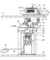
- the fuel supply device 1 As shown in FIGS. 1 to 3, the fuel supply device 1 according to the first embodiment of the present disclosure is mounted on a fuel tank 2 of a vehicle.
- the fuel supply device 1 supplies fuel from the fuel tank 2 to an internal combustion engine outside the tank 2.
- the vertical and horizontal directions in FIGS. 1 to 3 showing the mounting state of the fuel supply device 1 to the fuel tank 2 substantially coincide with the vertical and horizontal directions of the vehicle on the horizontal plane.
- the fuel supply device 1 includes a tank lid unit 10, a sub tank 20, a holding cover 30, an adjustment mechanism 40, a pump unit 50, and a liquid level sensor 60.
- elements 20, 30, 40, 50, 60 other than the tank lid unit 10 in the fuel supply device 1 are accommodated in the fuel tank 2.
- the tank lid unit 10 is assembled in a through hole 2b penetrating the top plate portion 2a in the fuel tank 2 formed in a hollow shape by resin. As shown in FIGS. 1 to 8, the tank lid unit 10 includes a lid body portion 11, a circuit housing portion 12, a drive circuit 13, a heat radiation cover portion 14, a pump terminal 15, a sensor terminal 16, a connection terminal 17, and a fuel pipe portion 18. have.
- the lid main body 11 is formed in a substantially flat plate shape as a whole with resin.
- the lid body 11 is fitted and assembled to the through hole 2b of the top plate 2a from the outside, thereby closing the through hole 2b above the fuel in the fuel tank 2.
- the fuel vapor in which the fuel in the fuel tank 2 is vaporized accumulates above the fuel.
- a permeable resin hereinafter simply referred to as “permeable resin” that allows fuel vapor to permeate, for example, polyacetal resin (POM) that has excellent fuel resistance is employed. ing.
- POM polyacetal resin
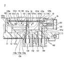
- the circuit casing 12 is integrally formed with the lid main body 11 by a permeable resin. As shown in FIGS. 6 and 7, the circuit housing 12 is formed in a bottomed cup shape with the internal space serving as the protection space 120. The circuit housing 12 is located above the lid body 11 in the external space 3 of the fuel tank 2. Due to this positional relationship, fuel vapor that has accumulated in the fuel tank 2 and has permeated through the lid main body 11 at the bottom 121 (hereinafter referred to as “housing bottom”) 121 of the circuit housing 12 can be transmitted to the protection space 120. ing.
- the drive circuit 13 is an electronic circuit accommodated in the protection space 120 in order to drive the fuel pump 52 (see FIG. 2) of the pump unit 50.
- the drive circuit 13 is formed by mounting a plurality of circuit elements (not shown) such as an IC, a chip capacitor, and a resistance element on both sides or one side of the printed wiring board 130.
- the printed wiring board 130 is a glass epoxy board, for example, and is formed in a flat plate shape.
- the printed wiring board 130 is held by a side part (hereinafter referred to as “housing side part”) 122 surrounding the protection space 120 above the housing bottom part 121. With such a holding form, the printed wiring board 130 is disposed in the upper space portion 120 a that is a separated portion of the protective space 120 that is spaced above the housing bottom 121.
- the heat dissipation cover part 14 is formed in a lid shape from metal.
- the heat radiating cover portion 14 is fitted and assembled to the upper end edge portion of the housing side portion 122 of the circuit housing portion 12, thereby closing the opening 122 a of the housing side portion 122.
- the heat radiating cover 14 is in contact with an IC (not shown) that generates a large amount of heat among circuit elements mounted on the printed wiring board 130 in the drive circuit 13, thereby radiating heat.
- the function can be demonstrated.
- the circuit housing portion 12 together with the heat dissipation cover portion 14 configured as described above cooperates to cover the protective space 120, thereby partitioning the protective space 120 from the external space 3 of the fuel tank 2 in a liquid-tight and air-tight manner, and driving.
- the circuit 13 is protected.
- the pump terminals 15 are formed in a stepped and elongated plate shape with metal, and a pair of pump terminals 15 are provided so as to extend in the vertical direction at intervals.
- an intermediate portion 152 between the end portions 150 and 151 in the extending direction is embedded in the lid main body portion 11 and the housing bottom portion 121 by metal insert molding into a permeable resin.
- One end 150 of each pump terminal 15 projects downward in the fuel tank 2, and is used for electrical connection with the fuel pump 52 in the pump unit 50.
- the other end portion 151 of each pump terminal 15 protrudes from the housing bottom 121 to the upper protection space 120, and is electrically connected to the printed wiring board 130 in the space upper portion 120 a of the space 120.
- each pump terminal 15 extends between the fuel pump 52 and the drive circuit 13 through the lid main body 11 and the housing bottom 121.
- the metal forming each pump terminal 15 for example, tin-plated brass having excellent fuel resistance is adopted.
- the electrical connection between each pump terminal 15 and the printed wiring board 130 is realized by soldering the upper end portions 151 of the terminals 15 through the through-holes of the printed wiring board 130 from below to above. Yes.
- the sensor terminals 16 are formed in a substantially L-shaped elongated flat plate shape with metal, and a pair of sensor terminals 16 are provided so as to extend in the vertical direction at intervals.
- an intermediate portion 162 between end portions 160 and 161 in the extending direction is embedded in the lid main body portion 11 and the casing bottom portion 121 by metal insert molding into a permeable resin.
- One end portion 160 of each sensor terminal 16 protrudes downward in the fuel tank 2 and is provided for electrical connection with the liquid level sensor 60.
- the other end portion 161 of each sensor terminal 16 protrudes to the side exposed in the external space 3 so that it can be electrically connected to an engine control circuit (not shown) of the internal combustion engine.
- the sensor signal of the liquid level sensor 60 is output to the engine control circuit.
- the metal forming each sensor terminal 16 for example, tin-plated brass similar to the pump terminal 15 is adopted.
- connection terminal 17 is formed in a substantially L-shaped elongated flat plate shape with metal, and a plurality of connection terminals 17 are provided so as to extend in the lateral direction at intervals.
- each connection terminal 17 an intermediate portion between the end portions 170 and 171 in the extending direction is embedded in the casing side portion 122 by metal insert molding into a permeable resin.
- One end portion 170 of each connection terminal 17 protrudes from the housing side portion 122 to the inner protection space 120, and is electrically connected to the drive circuit 13 in the space 120.
- the other end portion 171 of each connection terminal 17 protrudes to the side exposed in the external space 3 so that it can be electrically connected to the engine control circuit.
- the drive of the fuel pump 52 is controlled via the drive circuit 13 in accordance with a command from the engine control circuit.
- the forming metal of each connection terminal 17 for example, tin-plated brass similar to the pump terminal 15 is adopted.
- the fuel pipe portion 18 is integrally formed with the lid main body portion 11 by a permeable resin.
- the fuel pipe portion 18 protrudes downward from the lid main body portion 11 in the fuel tank 2, thereby serving for connection to the fuel filter 53 downstream of the fuel pump 52 in the pump unit 50.
- the fuel pipe portion 18 protrudes from the lid main body portion 11 into the upper external space 3 so as to be connected to a connection pipe portion (not shown) of the internal combustion engine.
- the sub tank 20 is formed in a bottomed cup shape from resin.
- the sub tank 20 is installed on the bottom 2 c of the fuel tank 2.
- the sub tank 20 stores the fuel transferred from the fuel tank 2 by the jet pump 55 in the pump unit 50.
- the holding cover 30 is formed in a lid shape with resin.
- the holding cover 30 is fitted and assembled to the upper edge of the sub tank 20.
- the holding cover 30 closes the opening of the sub tank 20 in the fuel tank 2 by this fitting form.
- the holding cover 30 has a holding hole 31 penetrating in the vertical direction.
- the holding cover 30 has one accommodating portion 32 extending in a cylindrical shape upward on each side of the holding hole 31.
- the adjusting mechanism 40 has a pair of support columns 41 and elastic members 42, respectively.
- Each support column 41 is formed of a metal in a cylindrical shape, and is arranged extending in the vertical direction. The upper end of each column 41 is attached to the lower part of the lid main body 11.
- Each column 41 is inserted into the corresponding accommodating portion 32 below the upper end portion. With this insertion form, each support column 41 is slidable in the vertical direction with respect to the holding cover 30.
- Each elastic member 42 is made of a metal coil spring, and is interposed between the corresponding accommodating portion 32 and the lid main body portion 11.
- Each elastic member 42 generates a restoring force by compressing and elastically deforming according to the relative position between the housing portion 32 and the lid main body portion 11. Due to the generation of the restoring force, each elastic member 42 presses the sub tank 20 integrally coupled to the holding cover 30 toward the lower bottom 2c side of the fuel tank 2.
- the pump unit 50 is accommodated in the sub tank 20 except for the upper part thereof.
- the pump unit 50 includes a suction filter 51, a fuel pump 52, a fuel filter 53, a pressure regulator 54, and a jet pump 55.
- the suction filter 51 is provided at the lowermost part of the pump unit 50.
- the suction filter 51 is connected to the suction port of the fuel pump 52.
- the suction filter 51 filters fuel sucked into the fuel pump 52 from the sub tank 20 to remove large foreign matters in the fuel.
- the fuel pump 52 is provided above the suction filter 51 in the pump unit 50.
- the fuel pump 52 is electrically connected to each pump terminal 15 via a flexible wiring 56 that can be bent. Under such electrical connection, the fuel pump 52 operates under drive control from the drive circuit 13 to pressurize and discharge the intake fuel from the suction filter 51.
- the fuel filter 53 is provided around the fuel pump 52 in the pump unit 50.
- the fuel filter 53 is formed by housing a filter element (not shown) such as a honeycomb filter medium in a filter case 53a.
- the filter case 53a is held by the inner peripheral portion of the holding hole 31 in a state of passing through the holding cover 30 in the vertical direction.
- the filter case 53 a is connected to the discharge port of the fuel pump 52 and is connected to the fuel pipe portion 18 via a flexible tube 57 that can be bent.
- the fuel filter 53 filters the fuel that is discharged from the fuel pump 52 into the filter case 53a and then travels toward the fuel pipe portion 18 to remove fine foreign matters in the fuel.
- the pressure regulator 54 is provided on the side of the fuel filter 53 in the pump unit 50.
- the pressure regulator 54 is connected to a formation part of a path toward the fuel pipe portion 18 in the filter case 53a.
- the pressure regulator 54 adjusts the pressure of the fuel supplied from the fuel filter 53 to the fuel pipe portion 18.
- the jet pump 55 is connected to a discharge port that discharges surplus fuel during pressure regulation in the pressure regulator 54.
- the jet pump 55 transfers the fuel in the fuel tank 2 into the sub tank 20 by generating a negative pressure by ejecting excess fuel discharged from the pressure regulator 54.
- the liquid level sensor 60 is fitted on the outer peripheral portion of the sub tank 20.
- the liquid level sensor 60 is a sender gauge in this embodiment, and is electrically connected to each sensor terminal 16 via a flexible wiring 61 that can be bent. Under such electrical connection, the liquid level sensor 60 detects the angle of rotation by the rotation of the arm 63 according to the vertical movement of the float 62 floating on the fuel in the fuel tank 2.
- the liquid level sensor 60 sends a sensor signal indicating the liquid level to each sensor terminal 16. Output.
- circuit casing and related structure Next, among the components included in the tank lid unit 10, the circuit housing portion 12 and the liquid-proof air-permeable membrane 19 that is a related structure will be described in detail.
- a housing bottom part 121 is provided so as to open a ventilation space 124 between the circuit body part 12 and the lid body part 11 below.
- the housing bottom 121 has a plurality of rib portions 121 a that divide the lower ventilation space 124 in the lateral direction and are connected to the lid body 11.
- the ventilation space 124 forms a dividing space portion 124a at a location where the rib portions 121a are sandwiched in the lateral direction.
- the divided space portions 124 a at each location are communicated with the space 3 by opening toward the external space 3.
- the intermediate portion 152 of each pump terminal 15 is embedded in one specific rib portion 121as in the present embodiment.
- the housing bottom 121 has a protruding portion 121 c so as to protrude above the lowermost inner surface 121 b facing the protection space 120.
- an intermediate portion 152 is embedded in any of the pump terminals 15 serving as the specific terminals in the overhang portion 121c located immediately above the specific rib portion 121as.
- the overhanging part 121c has an interface 121d formed between each pump terminal 15 and the intermediate part 152 among the pump terminals 15 via the specific rib part 121as at the upper end surface 121cu below the printed wiring board 130. It is exposed to the protective space 120.
- a space upper portion 120a in which the printed wiring board 130 is disposed in the protection space 120 and is electrically connected to the end portion 151 of each pump terminal 15 is an upper end surface that is an exposed portion of such an interface 121d. It is located above 121cu.
- the separation distance Da at which the upper end surface 121cu is separated from the lowermost inner surface 121b of the housing bottom 121 is the separation distance Db at which the lower mounting surface 130a of the printed wiring board 130 is separated from the lowermost inner surface 121b. It is set larger than half Db / 2.
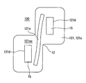
- the housing bottom 121 has a convex wall 121 e so as to protrude above the exposed upper end surface 121 cu of the interface 121 d in the overhang 121 c.
- the convex wall portion 121e is formed in a corrugated plate shape between the intermediate portions 152 of the pump terminals 15 spaced apart in the lateral direction.
- the convex wall portion 121e is formed with a protruding height that does not reach the printed wiring board 130 located in the upper space upper portion 120a.
- the circuit housing portion 12 has a vent hole 126 so as to penetrate the housing side portion 122 between the protective space 120 and the external space 3.
- the ventilation holes 126 are formed in a straight cylindrical hole shape, and a pair of ventilation holes 126 are provided in the horizontal direction.
- the opening area on the external space 3 side in each ventilation hole 126 is set to be smaller than the opening area of the ventilation space 124, that is, the total area of the opening area of the divided space portion 124a.
- the separation distance Dc at which the uppermost portion 126a of each vent hole 126 is separated from the lowermost inner surface 121b is such that the lower mounting surface 130a of the printed wiring board 130 is separated from the lowermost inner surface 121b.
- the liquid-proof air-permeable membrane 19 is formed into a circular thin film from an elastomer.
- a pair of liquid-proof air-permeable membranes 19 are provided corresponding to the respective air holes 126.
- Each liquid-proof air-permeable membrane 19 has a surface area larger than the opening area of the corresponding air hole 126 on the external space 3 side.
- Each liquid-proof air-permeable membrane 19 covers the entire opening on the external space 3 side of the corresponding air hole 126 by being attached to the outer side surface 122 b facing the external space 3 in the housing side portion 122.
- Each liquid-proof air-permeable membrane 19 has both the air-permeability that allows the discharge of fuel vapor from the corresponding vent hole 126 to the external space 3 and the liquid-proof property that restricts the entry of liquid into the corresponding vent hole 126. It has many fine holes of about 1 ⁇ m.
- the forming elastomer of each liquid-proof air-permeable membrane 19 for example, a material having a higher fuel vapor permeability than a water permeability is employed as a liquid.
- an elastomer or the like obtained by combining a polytetrafluoroethylene film and a polyurethane polymer is employed as the forming elastomer for each liquid-proof air-permeable membrane 19.
- each liquid-proof air-permeable membrane 19 is held from the outer peripheral side by a plurality of holding guides 122 c that are formed to protrude from the outer side surface 122 b of the housing side portion 122.
- the ventilation space 124 communicating with the external space 3 of the fuel tank 2 is opened between the lid main body 11 and the casing bottom 121 above it. Therefore, the fuel vapor that has permeated through the lid main body 11 is allowed to escape from the ventilation space 124 to the external space 3, thereby suppressing the permeation amount at the housing bottom 121.
- the intermediate portion 152 in the extending direction is embedded in the bottom 121 of the pump terminal 15 extending between the fuel pump 52 and the drive circuit 13 via the housing bottom 121. Therefore, since a clearance is generated at the interface 121d between the intermediate portion 152 and the housing bottom 121 of the burying destination, there is a concern that fuel vapor may enter the protective space 120 where the interface 121d is exposed through the clearance. The Therefore, according to the first embodiment, the interface 121 d between the casing bottom 121 and the intermediate portion 152 is exposed to the protective space 120 above the vent hole 126. According to this, the fuel vapor that has entered the protection space 120 is guided to the vent hole 126 below the exposed portion of the interface 121d due to the specific gravity heavier than air, so that it is difficult to reach the drive circuit 13. .
- the fuel vapor to the external space 3 from the vent hole 126 penetrating between the protective space 120 and the external space 3 in the housing side part 122 is covered by the liquid-proof air-permeable film 19 covering the vent hole 126. Discharge is allowed. Therefore, the fuel vapor that has entered the protection space 120 is gradually dissipated from the vent hole 126 to the external space 3, so that it is difficult to accumulate in the protection space 120 that protects the drive circuit 13. Furthermore, according to the first embodiment, the intrusion of liquid from the external space 3 to the vent hole 126 is regulated by the liquid-proof air-permeable film 19 that covers the vent hole 126.
- the liquid-proof air-permeable membrane 19 is attached to the outer side surface 122b facing the external space 3 in the casing side portion 122, so that the outer side surface even when pressed by the liquid pressure in the external space 3 It becomes difficult to peel off from 122b.
- the liquid-proof air-permeable membrane 19 that is difficult to peel off can exhibit a fuel vapor discharge permitting function and a liquid intrusion restricting function for a long time.
- the tank lid unit 10 of the first embodiment as described above, the fuel vapor in the fuel tank 2 is kept in contact with the drive circuit 13 and the liquid in the external space 3 is also prevented from coming into contact with the drive circuit 13. Thus, the failure of the drive circuit 13 can be avoided. Moreover, according to the fuel supply device 1 provided with such a tank lid unit 10, it is possible to avoid the failure of the drive circuit 13 and ensure the operational reliability of the fuel pump 52 driven by the circuit 13. Become.
- the ventilation space 124 is opened between the casing bottom 121 and the lid body 11 below the casing 121, so that the heat generated by the drive circuit 13 above the bottom 121 is not covered by the lid. It becomes difficult to be transmitted to the main body 11. According to this, it is possible to suppress the lid main body 11 from being thermally deformed and causing fuel vapor leakage from between the through hole 2b.
- the uppermost portion 126a of the air hole 126 and the exposed portion of the interface 121d with respect to the lowermost inner surface 121b of the housing bottom 121 are the distance Db of the drive circuit 13 from the lowermost inner surface 121b. They are separated by a distance Dc that is smaller than half and a distance Da that is larger than half. According to this, the exposed part of the interface 121d farther from the lowermost inner surface 121b than half of the separation distance Db is at an upper position with respect to the vent hole 126 closer to the lowermost inner surface 121b than half of the distance Db. Can be placed correctly. Therefore, even the fuel vapor that has entered the protection space 120 through the clearance of the interface 121d can suppress the contact itself with the drive circuit 13 and increase the reliability of the failure avoidance effect of the drive circuit 13.
- the drive circuit 13 disposed there is electrically connected to the pump terminal 15 at a spaced apart location from the housing bottom 121 above the exposed location of the interface 121d in the protective space 120. . Therefore, it is difficult for the fuel vapor to reach the electrical connection portion of the drive circuit 13 with the pump terminal 15 through the clearance of the interface 121d exposed below. Thereby, in the drive circuit 13, it becomes possible to avoid that fuel vapor contacts the electrical connection part with the pump terminal 15 and fails.
- the overhanging portion 121c that protrudes upward from the lowermost inner surface 121b facing the protection space 120 in the housing bottom 121 is an exposed portion of the interface 121d that forms the intermediate portion 152.
- the air hole 126 is spaced apart from the lowermost inner surface 121 b above the vent hole 126. According to this, the fuel vapor that has entered the protection space 120 through the clearance of the interface 121d can be reliably prevented from reaching the drive circuit 13, and the reliability of the failure avoidance effect of the drive circuit 13 can be improved. .
- each ventilation hole 126 is smaller than the opening area of the ventilation space 124 on the external space 3 side. Therefore, the size required to cover the vent hole 126 can be reduced as much as possible for the liquid-proof air-permeable membrane 19 attached to the outer side surface 122 b facing the external space 3 in the housing side portion 122. Moreover, since the opening area of the ventilation space 124 is larger than the opening area of each ventilation hole 126, the escape amount of the fuel vapor that has permeated through the lid main body 11 through the ventilation space 124 can be increased.
- the permeation amount that passes through the housing bottom 121 without allowing the fuel vapor to escape can be reduced, and in combination with the action of the vent hole 126 and the liquid-proof air-permeable membrane 19, A failure of the drive circuit 13 due to the permeated vapor can be avoided.
- the intermediate part 152 exposes the interface 121d to the protection space 120 through the rib part 121a of the casing bottom part 121.
- the rib portion 121 a is divided into the ventilation space 124 and connected to the lid main body portion 11. Can be reinforced by using. According to this, it is possible to maintain the shape of the protection space 120 that protects the drive circuit 13 by the circuit housing portion 12, and to avoid a failure of the drive circuit 13 due to the deformation of the housing portion 12.
- the convex wall portion is located above the exposed portion of the interface 121d formed by the intermediate portion 152 of the terminals 15 and the housing bottom portion 121. 121e is formed to protrude. Therefore, even if the liquid in the external space 3 enters the protective space 120, the distance that the intruding liquid travels between the pump terminals 15 along the surface of the housing bottom 121 is determined by the protrusion of the convex wall 121e. Can be increased accordingly. According to this, it is possible to avoid the insulation state between the pump terminals 15 being lowered by the liquid and causing the drive circuit 13 to malfunction.
- the second embodiment of the present disclosure is a modification of the first embodiment.
- the housing bottom portion 2121 of the second embodiment has a concave wall portion 2121e so as to protrude downward from the upper end surface 121cu of the protruding portion 121c where the interface 121d is exposed.
- the concave wall portion 2121e is formed in a rectangular groove shape between the intermediate portions 152 of the pump terminals 15 spaced apart in the lateral direction. At the same time, the concave wall portion 2121e is formed with a depth that does not reach the lowermost inner surface 121b.
- the concave wall portion is formed below the exposed portion of the interface 121d where the intermediate portion 152 of the terminals 15 forms the housing bottom portion 121.
- a recess 2121e is formed. Therefore, even if the liquid in the external space 3 enters the protective space 120, the distance that the intruding liquid travels between the pump terminals 15 along the surface of the housing bottom 121 is determined by the concave portion of the concave wall 2121e. Can be increased accordingly. According to this, it is possible to avoid the insulation state between the pump terminals 15 being lowered by the liquid and causing the drive circuit 13 to malfunction. Other operational effects can be exhibited on the same principle as in the first embodiment.
- the protective space 120 may be filled with a filler such as an epoxy resin that protects the drive circuit 13. Even in this case, the fuel vapor and the liquid reach the drive circuit 13 through the clearance between the circuit housing portion 12 and the filler and the air holes 126, respectively, as in the first and second embodiments. It can be suppressed by the same principle.
- the one air-hole 126 instead of the liquid-proof air-permeable film 19, the one air-hole 126 may be covered with a liquid-proof film without air permeability or the same permeable resin as the resin for forming the elements 11 and 12.
- the opening area of each ventilation hole 126 is set larger than the opening area of the ventilation space 124 (the total area of the opening area of the divided space portion 124a) on the external space 3 side. May be.
- the number of pump terminals 15 may be set to one or a plurality other than a pair.
- the convex wall portion 121e or the concave wall portion 2121e may be provided only in a part of the portions between the pump terminals 15. In this case, among the three or more pump terminals 15, only the terminal 15 provided with the convex wall part 121e or the concave wall part 2121e between them corresponds to the specific terminal.
- the convex wall part 121e or the concave wall part 2121e may not be provided at all.
- the separation distance Dc of the uppermost portion 126a and the separation distance Da of the exposed portion are set to You may set larger than the half of the separation distance Db.
- the separation distance Dc of the uppermost portion 126a and the separation distance Da of the exposed portion are driven. You may set smaller than the half of the separation distance Db of the circuit 13.
Landscapes
- Engineering & Computer Science (AREA)
- Chemical & Material Sciences (AREA)
- Combustion & Propulsion (AREA)
- Mechanical Engineering (AREA)
- Power Engineering (AREA)
- General Engineering & Computer Science (AREA)
- Life Sciences & Earth Sciences (AREA)
- Sustainable Development (AREA)
- Sustainable Energy (AREA)
- Transportation (AREA)
- Microelectronics & Electronic Packaging (AREA)
- Cooling, Air Intake And Gas Exhaust, And Fuel Tank Arrangements In Propulsion Units (AREA)
Abstract
Description
燃料タンクの貫通孔に組み付けられ、燃料タンク内の燃料ポンプを駆動するために駆動回路を収容するタンク蓋ユニットにおいて、
燃料蒸気を透過させる透過性樹脂により形成され、貫通孔を閉塞する蓋本体部と、
透過性樹脂により蓋本体部の上方に一体成形され、駆動回路を保護する保護空間を燃料タンクの外部空間から仕切る回路筐体部であって、外部空間と連通する通気空間を蓋本体部との間にあける底部と、底部の上方において保護空間を囲む側部と、側部において保護空間と外部空間との間を貫通する通気孔とを、有する回路筐体部と、
底部を経由して燃料ポンプと駆動回路との間を延伸するように、当該延伸方向の中間部が底部に埋設されるターミナルであって、底部と中間部との界面が通気孔よりも上方において、保護空間に露出するターミナルと、
側部のうち外部空間に面する外側面に装着されて通気孔を覆うことにより、通気孔から外部空間への燃料蒸気の排出を許容し且つ外部空間から通気孔への液体の侵入を規制する防液通気膜とを、備える。
燃料タンク内から燃料タンク外へ向かって燃料を供給する燃料ポンプと共に、
第一開示のタンク蓋ユニットが設けられる。
図1~3に示すように、本開示の第一実施形態による燃料供給装置1は、車両の燃料タンク2に搭載される。燃料供給装置1は、燃料タンク2内から同タンク2外の内燃機関へと燃料を供給する。尚、燃料タンク2への燃料供給装置1の搭載状態を示す各図1~3の上下方向及び横方向は、水平面上における車両の鉛直方向及び水平方向と実質的に一致している。
まず、燃料供給装置1の基本構成につき、説明する。燃料供給装置1は、タンク蓋ユニット10、サブタンク20、保持カバー30、調整機構40、ポンプユニット50及び液面センサ60を備えている。ここで、燃料供給装置1のうちタンク蓋ユニット10以外の要素20,30,40,50,60は、燃料タンク2内に収容される。
次に、タンク蓋ユニット10が備える構成要素のうち特に、回路筐体部12とその関連構造である防液通気膜19とについて、詳細に説明する。
以上説明した第一実施形態の作用効果を、以下に説明する。
図11に示すように本開示の第二実施形態は、第一実施形態の変形例である。第二実施形態の筐体底部2121は、張出部121cのうち界面121dの露出した上端面121cuよりも下方へ突出するように、凹壁部2121eを有している。凹壁部2121eは、横方向に間隔をあけた各ポンプターミナル15の中間部152間において、矩形溝状に形成されている。それと共に凹壁部2121eは、下方の最下内面121bまでは達しない深さをもって、形成されている。
以上、本開示の複数の実施形態について説明したが、本開示は、それらの実施形態に限定して解釈されるものではなく、本開示の要旨を逸脱しない範囲内において種々の実施形態及び組み合わせに適用することができる。
Claims (9)
- 燃料タンク(2)の貫通孔(2b)に組み付けられ、前記燃料タンク内の燃料ポンプ(52)を駆動するために駆動回路(13)を収容するタンク蓋ユニット(10)において、
燃料蒸気を透過させる透過性樹脂により形成され、前記貫通孔を閉塞する蓋本体部(11)と、
前記透過性樹脂により前記蓋本体部の上方に一体成形され、前記駆動回路を保護する保護空間(120)を前記燃料タンクの外部空間(3)から仕切る回路筐体部(12)であって、前記外部空間と連通する通気空間(124)を前記蓋本体部との間にあける底部(121,2121)と、前記底部の上方において前記保護空間を囲む側部(122)と、前記側部において前記保護空間と前記外部空間との間を貫通する通気孔(126)とを、有する回路筐体部と、
前記底部を経由して前記燃料ポンプと前記駆動回路との間を延伸するように、当該延伸方向の中間部(152)が前記底部に埋設されるターミナル(15)であって、前記底部と前記中間部との界面(121d)が前記通気孔よりも上方において、前記保護空間に露出するターミナルと、
前記側部のうち前記外部空間に面する外側面(122b)に装着されて前記通気孔を覆うことにより、前記通気孔から前記外部空間への前記燃料蒸気の排出を許容し且つ前記外部空間から前記通気孔への液体の侵入を規制する防液通気膜(19)とを、備えるタンク蓋ユニット。 - 前記駆動回路は、前記保護空間のうち前記界面が露出する露出箇所(121cu)よりも上方において、前記底部から離間して配置され、
前記底部の最下内面(121b)に対する前記通気孔の最上部(126a)の離間距離(Dc)は、前記最下内面に対する前記駆動回路の離間距離(Db)の半分よりも小さく、
前記最下内面に対する前記露出箇所の離間距離(Da)は、前記最下内面に対する前記駆動回路の離間距離(Db)の半分よりも大きい請求項1に記載のタンク蓋ユニット。 - 前記駆動回路は、前記保護空間のうち前記界面が露出する露出箇所(121cu)よりも上方において、前記底部から離間した離間箇所(120a)に配置され、
前記ターミナルは、前記離間箇所において前記駆動回路と電気接続される請求項1又は2に記載のタンク蓋ユニット。 - 前記底部は、前記保護空間に面する最下内面(121b)よりも上方へ張り出す張出部(121c)を、有し、
前記保護空間のうち前記中間部が前記張出部となす前記界面の露出箇所(121cu)は、前記通気孔よりも前記最下内面から上方に離間する請求項1~3のいずれか一項に記載のタンク蓋ユニット。 - 前記外部空間側において前記通気孔の開口面積は、前記通気空間の開口面積よりも小さい請求項1~4のいずれか一項に記載のタンク蓋ユニット。
- 前記底部は、前記通気空間を分断して前記蓋本体部に接続されるリブ部(121a)を、有し、
前記中間部は、前記リブ部を経由して前記底部との前記界面を前記保護空間に露出させる請求項1~5のいずれか一項に記載のタンク蓋ユニット。 - 前記ターミナルとして、互いに間をあける複数の特定ターミナルを、備え、
前記底部(121)には、前記保護空間において各前記特定ターミナルの前記中間部が前記底部となす前記界面の露出箇所(121cu)よりも上方へ突出する凸壁部(121e)が、各前記特定ターミナルの間に形成される請求項1~6のいずれか一項に記載のタンク蓋ユニット。 - 前記ターミナルとして、互いに間をあける複数の特定ターミナルを、備え、
前記底部(2121)には、前記保護空間において各前記特定ターミナルの前記中間部が前記底部となす前記界面の露出箇所よりも下方へ凹陥する凹壁部(2121e)が、各前記特定ターミナルの間に形成される請求項1~6のいずれか一項に記載のタンク蓋ユニット。 - 燃料タンク内から前記燃料タンク外へ向かって燃料を供給する燃料ポンプ(52)と共に、
請求項1~8のいずれか一項に記載のタンク蓋ユニット(10)が設けられた燃料供給装置。
Priority Applications (3)
| Application Number | Priority Date | Filing Date | Title |
|---|---|---|---|
| KR1020167037056A KR20170012483A (ko) | 2014-07-22 | 2015-07-21 | 탱크 덮개 유닛 및 연료 공급 장치 |
| US15/327,783 US10072621B2 (en) | 2014-07-22 | 2015-07-21 | Tank lid unit and fuel supply device |
| KR1020187030876A KR101978839B1 (ko) | 2014-07-22 | 2015-07-21 | 탱크 덮개 유닛 및 연료 공급 장치 |
Applications Claiming Priority (2)
| Application Number | Priority Date | Filing Date | Title |
|---|---|---|---|
| JP2014-148630 | 2014-07-22 | ||
| JP2014148630A JP6233227B2 (ja) | 2014-07-22 | 2014-07-22 | タンク蓋ユニット及び燃料供給装置 |
Publications (1)
| Publication Number | Publication Date |
|---|---|
| WO2016013204A1 true WO2016013204A1 (ja) | 2016-01-28 |
Family
ID=55162748
Family Applications (1)
| Application Number | Title | Priority Date | Filing Date |
|---|---|---|---|
| PCT/JP2015/003634 Ceased WO2016013204A1 (ja) | 2014-07-22 | 2015-07-21 | タンク蓋ユニット及び燃料供給装置 |
Country Status (4)
| Country | Link |
|---|---|
| US (1) | US10072621B2 (ja) |
| JP (1) | JP6233227B2 (ja) |
| KR (2) | KR101978839B1 (ja) |
| WO (1) | WO2016013204A1 (ja) |
Families Citing this family (10)
| Publication number | Priority date | Publication date | Assignee | Title |
|---|---|---|---|---|
| JP6495093B2 (ja) * | 2015-05-14 | 2019-04-03 | 愛三工業株式会社 | 燃料供給装置 |
| US10259313B2 (en) * | 2016-03-30 | 2019-04-16 | Walbro Llc | Fuel pump assembly with removable supports |
| US10549631B2 (en) | 2016-03-30 | 2020-02-04 | Walbro Llc | Fuel pump assembly with removable and/or movable supports |
| KR101821588B1 (ko) * | 2016-04-22 | 2018-01-25 | 주식회사 코아비스 | 방열 성능을 개선한 연료펌프 모듈 및 이를 제조하는 연료펌프 모듈 제조방법 |
| WO2019122201A1 (en) | 2017-12-20 | 2019-06-27 | Plastic Omnium Advanced Innovation And Research | Fuel tank comprising a temperature sensor |
| WO2019122219A1 (en) * | 2017-12-20 | 2019-06-27 | Plastic Omnium Advanced Innovation And Research | A tank comprising a pressure sensor and another sensor |
| KR102006850B1 (ko) * | 2018-01-22 | 2019-08-02 | 만도헬라일렉트로닉스(주) | 차량용 연료탱크의 커버 어셈블리 |
| KR102575414B1 (ko) * | 2018-06-18 | 2023-09-05 | 현대자동차주식회사 | 차량용 연료시스템의 컨트롤러 |
| US11614095B2 (en) * | 2020-01-07 | 2023-03-28 | Honda Motor Co., Ltd. | Fuel pump cover |
| IT202100031277A1 (it) * | 2021-12-14 | 2023-06-14 | Taco Italia S R L | Circolatore di fluido |
Citations (2)
| Publication number | Priority date | Publication date | Assignee | Title |
|---|---|---|---|---|
| JP2006103624A (ja) * | 2004-10-08 | 2006-04-20 | Hitachi Ltd | 燃料タンク用蓋体ユニット |
| JP2008291701A (ja) * | 2007-05-23 | 2008-12-04 | Denso Corp | 燃料供給装置 |
Family Cites Families (13)
| Publication number | Priority date | Publication date | Assignee | Title |
|---|---|---|---|---|
| JP3794879B2 (ja) * | 1999-09-30 | 2006-07-12 | 株式会社日立製作所 | 燃料供給装置 |
| JP2005155602A (ja) * | 2003-11-07 | 2005-06-16 | Denso Corp | 燃料供給装置 |
| JP3936327B2 (ja) | 2003-11-25 | 2007-06-27 | 東海興業株式会社 | 樹脂成形防水ケース部材 |
| JP2007056820A (ja) * | 2005-08-26 | 2007-03-08 | Denso Corp | 燃料供給装置 |
| US7497208B2 (en) * | 2006-07-11 | 2009-03-03 | Denso Corporation | Fuel supply device having shielded in-tank fuel pump for use in automotive vehicle |
| JP4737126B2 (ja) * | 2007-03-27 | 2011-07-27 | 株式会社デンソー | 燃料タンク用電気コネクタ |
| US7806109B2 (en) * | 2007-06-01 | 2010-10-05 | Aisan Kogyo Kabushiki Kaisha | Fuel supply apparatus |
| JP2009036101A (ja) * | 2007-08-01 | 2009-02-19 | Aisan Ind Co Ltd | 燃料供給装置 |
| JP2009091936A (ja) * | 2007-10-05 | 2009-04-30 | Aisan Ind Co Ltd | 燃料ポンプ用制御装置 |
| JP4969661B2 (ja) | 2010-01-20 | 2012-07-04 | 三菱電機株式会社 | 電子制御ユニット及びその製造方法 |
| JP2014053382A (ja) | 2012-09-05 | 2014-03-20 | Denso Corp | 筺体及び電子装置 |
| KR101543100B1 (ko) * | 2013-12-02 | 2015-08-07 | 현대자동차주식회사 | 컨트롤러 일체형 연료펌프 모듈 |
| US9745931B2 (en) * | 2015-12-01 | 2017-08-29 | Delphi Technologies, Inc. | Fuel system with a fuel pump control module and a heat sink |
-
2014
- 2014-07-22 JP JP2014148630A patent/JP6233227B2/ja not_active Expired - Fee Related
-
2015
- 2015-07-21 US US15/327,783 patent/US10072621B2/en not_active Expired - Fee Related
- 2015-07-21 WO PCT/JP2015/003634 patent/WO2016013204A1/ja not_active Ceased
- 2015-07-21 KR KR1020187030876A patent/KR101978839B1/ko not_active Expired - Fee Related
- 2015-07-21 KR KR1020167037056A patent/KR20170012483A/ko not_active Abandoned
Patent Citations (2)
| Publication number | Priority date | Publication date | Assignee | Title |
|---|---|---|---|---|
| JP2006103624A (ja) * | 2004-10-08 | 2006-04-20 | Hitachi Ltd | 燃料タンク用蓋体ユニット |
| JP2008291701A (ja) * | 2007-05-23 | 2008-12-04 | Denso Corp | 燃料供給装置 |
Also Published As
| Publication number | Publication date |
|---|---|
| JP6233227B2 (ja) | 2017-11-22 |
| JP2016023592A (ja) | 2016-02-08 |
| US20170211530A1 (en) | 2017-07-27 |
| KR101978839B1 (ko) | 2019-05-15 |
| US10072621B2 (en) | 2018-09-11 |
| KR20170012483A (ko) | 2017-02-02 |
| KR20180120781A (ko) | 2018-11-06 |
Similar Documents
| Publication | Publication Date | Title |
|---|---|---|
| JP6233227B2 (ja) | タンク蓋ユニット及び燃料供給装置 | |
| CN109094481B (zh) | 电子部件单元、线束以及通气部防水构造 | |
| JP6390412B2 (ja) | タンク蓋ユニット及び燃料供給装置 | |
| JP3936327B2 (ja) | 樹脂成形防水ケース部材 | |
| WO2014073096A1 (ja) | 電子部品収容構造 | |
| CN108291506B (zh) | 燃料供给装置 | |
| JP2006103624A (ja) | 燃料タンク用蓋体ユニット | |
| JP2005129861A (ja) | 樹脂成形防水ケース部材 | |
| JP6459947B2 (ja) | タンク蓋ユニット及び燃料供給装置 | |
| CN107076072A (zh) | 燃料供给装置 | |
| JP2012136172A (ja) | 電子装置 | |
| JP4285139B2 (ja) | 車両用液圧制御装置 | |
| CN115397146A (zh) | 用于电子部件的外壳和控制单元 | |
| JP2004357462A (ja) | 防水構造を備えた車両用制御器 | |
| JP6683010B2 (ja) | 電子装置、及び、フィルタ装置 | |
| CN110050121B (zh) | 燃料箱盖单元 | |
| JP2004052564A (ja) | 燃料タンクの圧力調整バルブ | |
| KR102464635B1 (ko) | 전자 제어 장치 | |
| US7299791B2 (en) | Pump spacer/dampening structure for fuel delivery system | |
| JP2019041559A (ja) | 電子制御ユニット | |
| JP2011035239A (ja) | 通気筐体 | |
| EP4539497A1 (en) | Microphone assembly for a vehicle with a housing cover comprising a first grid and a second grid | |
| JP2005047428A (ja) | 車両用液圧制御装置 |
Legal Events
| Date | Code | Title | Description |
|---|---|---|---|
| 121 | Ep: the epo has been informed by wipo that ep was designated in this application |
Ref document number: 15823943 Country of ref document: EP Kind code of ref document: A1 |
|
| ENP | Entry into the national phase |
Ref document number: 20167037056 Country of ref document: KR Kind code of ref document: A |
|
| WWE | Wipo information: entry into national phase |
Ref document number: 15327783 Country of ref document: US |
|
| NENP | Non-entry into the national phase |
Ref country code: DE |
|
| 122 | Ep: pct application non-entry in european phase |
Ref document number: 15823943 Country of ref document: EP Kind code of ref document: A1 |