WO2016013129A1 - ピストンおよび緩衝器 - Google Patents
ピストンおよび緩衝器 Download PDFInfo
- Publication number
- WO2016013129A1 WO2016013129A1 PCT/JP2014/075585 JP2014075585W WO2016013129A1 WO 2016013129 A1 WO2016013129 A1 WO 2016013129A1 JP 2014075585 W JP2014075585 W JP 2014075585W WO 2016013129 A1 WO2016013129 A1 WO 2016013129A1
- Authority
- WO
- WIPO (PCT)
- Prior art keywords
- piston
- port
- valve seat
- piston body
- cylinder
- Prior art date
- Legal status (The legal status is an assumption and is not a legal conclusion. Google has not performed a legal analysis and makes no representation as to the accuracy of the status listed.)
- Ceased
Links
Images





Classifications
-
- F—MECHANICAL ENGINEERING; LIGHTING; HEATING; WEAPONS; BLASTING
- F16—ENGINEERING ELEMENTS AND UNITS; GENERAL MEASURES FOR PRODUCING AND MAINTAINING EFFECTIVE FUNCTIONING OF MACHINES OR INSTALLATIONS; THERMAL INSULATION IN GENERAL
- F16F—SPRINGS; SHOCK-ABSORBERS; MEANS FOR DAMPING VIBRATION
- F16F9/00—Springs, vibration-dampers, shock-absorbers, or similarly-constructed movement-dampers using a fluid or the equivalent as damping medium
- F16F9/32—Details
- F16F9/3207—Constructional features
- F16F9/3214—Constructional features of pistons
-
- F—MECHANICAL ENGINEERING; LIGHTING; HEATING; WEAPONS; BLASTING
- F16—ENGINEERING ELEMENTS AND UNITS; GENERAL MEASURES FOR PRODUCING AND MAINTAINING EFFECTIVE FUNCTIONING OF MACHINES OR INSTALLATIONS; THERMAL INSULATION IN GENERAL
- F16F—SPRINGS; SHOCK-ABSORBERS; MEANS FOR DAMPING VIBRATION
- F16F9/00—Springs, vibration-dampers, shock-absorbers, or similarly-constructed movement-dampers using a fluid or the equivalent as damping medium
- F16F9/10—Springs, vibration-dampers, shock-absorbers, or similarly-constructed movement-dampers using a fluid or the equivalent as damping medium using liquid only; using a fluid of which the nature is immaterial
- F16F9/14—Devices with one or more members, e.g. pistons, vanes, moving to and fro in chambers and using throttling effect
- F16F9/16—Devices with one or more members, e.g. pistons, vanes, moving to and fro in chambers and using throttling effect involving only straight-line movement of the effective parts
- F16F9/18—Devices with one or more members, e.g. pistons, vanes, moving to and fro in chambers and using throttling effect involving only straight-line movement of the effective parts with a closed cylinder and a piston separating two or more working spaces therein
- F16F9/19—Devices with one or more members, e.g. pistons, vanes, moving to and fro in chambers and using throttling effect involving only straight-line movement of the effective parts with a closed cylinder and a piston separating two or more working spaces therein with a single cylinder and of single-tube type
-
- F—MECHANICAL ENGINEERING; LIGHTING; HEATING; WEAPONS; BLASTING
- F16—ENGINEERING ELEMENTS AND UNITS; GENERAL MEASURES FOR PRODUCING AND MAINTAINING EFFECTIVE FUNCTIONING OF MACHINES OR INSTALLATIONS; THERMAL INSULATION IN GENERAL
- F16F—SPRINGS; SHOCK-ABSORBERS; MEANS FOR DAMPING VIBRATION
- F16F9/00—Springs, vibration-dampers, shock-absorbers, or similarly-constructed movement-dampers using a fluid or the equivalent as damping medium
- F16F9/32—Details
- F16F9/34—Special valve constructions; Shape or construction of throttling passages
-
- F—MECHANICAL ENGINEERING; LIGHTING; HEATING; WEAPONS; BLASTING
- F16—ENGINEERING ELEMENTS AND UNITS; GENERAL MEASURES FOR PRODUCING AND MAINTAINING EFFECTIVE FUNCTIONING OF MACHINES OR INSTALLATIONS; THERMAL INSULATION IN GENERAL
- F16F—SPRINGS; SHOCK-ABSORBERS; MEANS FOR DAMPING VIBRATION
- F16F9/00—Springs, vibration-dampers, shock-absorbers, or similarly-constructed movement-dampers using a fluid or the equivalent as damping medium
- F16F9/32—Details
- F16F9/34—Special valve constructions; Shape or construction of throttling passages
- F16F9/348—Throttling passages in the form of annular discs or other plate-like elements which may or may not have a spring action, operating in opposite directions or singly, e.g. annular discs positioned on top of the valve or piston body
-
- F—MECHANICAL ENGINEERING; LIGHTING; HEATING; WEAPONS; BLASTING
- F16—ENGINEERING ELEMENTS AND UNITS; GENERAL MEASURES FOR PRODUCING AND MAINTAINING EFFECTIVE FUNCTIONING OF MACHINES OR INSTALLATIONS; THERMAL INSULATION IN GENERAL
- F16F—SPRINGS; SHOCK-ABSORBERS; MEANS FOR DAMPING VIBRATION
- F16F9/00—Springs, vibration-dampers, shock-absorbers, or similarly-constructed movement-dampers using a fluid or the equivalent as damping medium
- F16F9/32—Details
- F16F9/34—Special valve constructions; Shape or construction of throttling passages
- F16F9/348—Throttling passages in the form of annular discs or other plate-like elements which may or may not have a spring action, operating in opposite directions or singly, e.g. annular discs positioned on top of the valve or piston body
- F16F9/3481—Throttling passages in the form of annular discs or other plate-like elements which may or may not have a spring action, operating in opposite directions or singly, e.g. annular discs positioned on top of the valve or piston body characterised by shape or construction of throttling passages in piston
-
- F—MECHANICAL ENGINEERING; LIGHTING; HEATING; WEAPONS; BLASTING
- F16—ENGINEERING ELEMENTS AND UNITS; GENERAL MEASURES FOR PRODUCING AND MAINTAINING EFFECTIVE FUNCTIONING OF MACHINES OR INSTALLATIONS; THERMAL INSULATION IN GENERAL
- F16F—SPRINGS; SHOCK-ABSORBERS; MEANS FOR DAMPING VIBRATION
- F16F9/00—Springs, vibration-dampers, shock-absorbers, or similarly-constructed movement-dampers using a fluid or the equivalent as damping medium
- F16F9/32—Details
- F16F9/56—Means for adjusting the length of, or for locking, the spring or damper, e.g. at the end of the stroke
-
- B—PERFORMING OPERATIONS; TRANSPORTING
- B22—CASTING; POWDER METALLURGY
- B22F—WORKING METALLIC POWDER; MANUFACTURE OF ARTICLES FROM METALLIC POWDER; MAKING METALLIC POWDER; APPARATUS OR DEVICES SPECIALLY ADAPTED FOR METALLIC POWDER
- B22F3/00—Manufacture of workpieces or articles from metallic powder characterised by the manner of compacting or sintering; Apparatus specially adapted therefor ; Presses and furnaces
- B22F3/02—Compacting only
- B22F3/03—Press-moulding apparatus therefor
- B22F2003/033—Press-moulding apparatus therefor with multiple punches working in the same direction
-
- B—PERFORMING OPERATIONS; TRANSPORTING
- B22—CASTING; POWDER METALLURGY
- B22F—WORKING METALLIC POWDER; MANUFACTURE OF ARTICLES FROM METALLIC POWDER; MAKING METALLIC POWDER; APPARATUS OR DEVICES SPECIALLY ADAPTED FOR METALLIC POWDER
- B22F3/00—Manufacture of workpieces or articles from metallic powder characterised by the manner of compacting or sintering; Apparatus specially adapted therefor ; Presses and furnaces
- B22F3/02—Compacting only
- B22F3/03—Press-moulding apparatus therefor
-
- B—PERFORMING OPERATIONS; TRANSPORTING
- B22—CASTING; POWDER METALLURGY
- B22F—WORKING METALLIC POWDER; MANUFACTURE OF ARTICLES FROM METALLIC POWDER; MAKING METALLIC POWDER; APPARATUS OR DEVICES SPECIALLY ADAPTED FOR METALLIC POWDER
- B22F5/00—Manufacture of workpieces or articles from metallic powder characterised by the special shape of the product
- B22F5/008—Manufacture of workpieces or articles from metallic powder characterised by the special shape of the product of engine cylinder parts or of piston parts other than piston rings
-
- B—PERFORMING OPERATIONS; TRANSPORTING
- B60—VEHICLES IN GENERAL
- B60G—VEHICLE SUSPENSION ARRANGEMENTS
- B60G2202/00—Indexing codes relating to the type of spring, damper or actuator
- B60G2202/20—Type of damper
- B60G2202/24—Fluid damper
-
- F—MECHANICAL ENGINEERING; LIGHTING; HEATING; WEAPONS; BLASTING
- F16—ENGINEERING ELEMENTS AND UNITS; GENERAL MEASURES FOR PRODUCING AND MAINTAINING EFFECTIVE FUNCTIONING OF MACHINES OR INSTALLATIONS; THERMAL INSULATION IN GENERAL
- F16F—SPRINGS; SHOCK-ABSORBERS; MEANS FOR DAMPING VIBRATION
- F16F2226/00—Manufacturing; Treatments
- F16F2226/04—Assembly or fixing methods; methods to form or fashion parts
-
- F—MECHANICAL ENGINEERING; LIGHTING; HEATING; WEAPONS; BLASTING
- F16—ENGINEERING ELEMENTS AND UNITS; GENERAL MEASURES FOR PRODUCING AND MAINTAINING EFFECTIVE FUNCTIONING OF MACHINES OR INSTALLATIONS; THERMAL INSULATION IN GENERAL
- F16F—SPRINGS; SHOCK-ABSORBERS; MEANS FOR DAMPING VIBRATION
- F16F2232/00—Nature of movement
- F16F2232/08—Linear
-
- F—MECHANICAL ENGINEERING; LIGHTING; HEATING; WEAPONS; BLASTING
- F16—ENGINEERING ELEMENTS AND UNITS; GENERAL MEASURES FOR PRODUCING AND MAINTAINING EFFECTIVE FUNCTIONING OF MACHINES OR INSTALLATIONS; THERMAL INSULATION IN GENERAL
- F16F—SPRINGS; SHOCK-ABSORBERS; MEANS FOR DAMPING VIBRATION
- F16F9/00—Springs, vibration-dampers, shock-absorbers, or similarly-constructed movement-dampers using a fluid or the equivalent as damping medium
- F16F9/06—Springs, vibration-dampers, shock-absorbers, or similarly-constructed movement-dampers using a fluid or the equivalent as damping medium using both gas and liquid
- F16F9/064—Units characterised by the location or shape of the expansion chamber
- F16F9/065—Expansion chamber provided on the upper or lower end of a damper, separately there from or laterally on the damper
Definitions
- the present invention relates to a piston and a shock absorber.
- a piston that is slidably inserted into a cylinder of a shock absorber divides the inside of the cylinder into two pressure chambers, and the expansion side port through which hydraulic oil passes when the shock absorber extends and the shock absorber contract And a pressure side port through which hydraulic oil passes.
- Leaf valves are stacked above and below this type of piston. The outlet ends of the extension side port and the compression side port are opened and closed by these leaf valves. When the shock absorber expands and contracts, a damping force is generated by the leaf valve providing resistance to the flow of hydraulic oil passing through the expansion side port and the compression side port.
- the piston speed is low in the low-speed region, particularly with respect to the damping force characteristic on the extension side, from the viewpoint of improving the riding comfort of the vehicle. Therefore, a characteristic is required in which the damping force quickly rises and the rate of increase of the damping force with respect to the piston speed becomes small when the piston speed reaches the high speed range.
- the shock absorber can firmly suppress the vibration of the vehicle body when the piston speed is in the low speed range, and the damping force is excessive when the piston speed is in the high speed range. Can be suppressed. As a result, the riding comfort of the vehicle can be improved.
- JP2013-190044A discloses a shock absorber having these configurations.
- the leaf valve is easily bent and a gap formed between the valve seat and the leaf valve is increased when the leaf valve is separated from the valve seat.
- the resistance of the port is small, the resistance given to the flow of hydraulic oil when the piston speed is in the high speed range is reduced.
- this shock absorber can realize the aforementioned damping force characteristics.
- the cross-sectional area of the port is large.
- the port cross-sectional area by making the cross-sectional shape of the port arc.
- the arc-shaped port is provided in the piston, it can be performed by drilling, but the processing time is increased and the cost is increased.
- the piston is generally manufactured by sintering, when such a port is formed in the piston, the port is formed by a mold.
- the piston is manufactured by inserting a port forming die into the sintered die.
- the port is arcuate
- the cross-sectional shape of the mold that forms the port is also arcuate. For this reason, the cost which manufactures a type
- This invention aims at reducing the manufacturing cost of a piston and a buffer.
- One or a plurality of ports that communicate with the other end along the direction, and the cross-sectional shape of the port is a rounded rectangle that does not change in the middle and is an arc with both ends on the same circumference
- a cylinder and a piston that is slidably inserted into the cylinder and divides the cylinder into an extension side chamber and a pressure side chamber, and the piston has a disk shape.
- a shock absorber is provided in which the cross-sectional shape of the port is a rounded rectangle and does not change in the middle, and both ends are circular arcs on the same circumference.
- FIG. 1 is a longitudinal sectional view of a shock absorber according to an embodiment of the present invention.
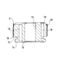
- FIG. 2 is an enlarged longitudinal sectional view of the piston of the shock absorber according to the embodiment of the present invention.
- FIG. 3 is a bottom view of the piston body.
- FIG. 4 is a plan view of the piston body.
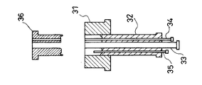
- FIG. 5 is a cross-sectional view of a mold for molding a piston.
- FIG. 6A is a diagram showing a mold in a ready state before being filled with a metal powder material.
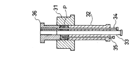
- FIG. 6B is a view showing a mold filled with a metal powder material.
- FIG. 6C is a diagram showing a state in which the metal powder material is pressed with a mold.
- FIGS. 1, 2 and 5 the top of FIGS. 1, 2 and 5 is referred to as “upper (upper, upper end, upper surface, etc.)”, and the lower part of FIGS. explain.
- the shock absorber D includes a cylinder 1, a piston 2 that is slidably inserted into the cylinder 1 and divides the cylinder 1 into an extension side chamber R ⁇ b> 1 and a pressure side chamber R ⁇ b> 2, and one end is a piston 2. And a piston rod 3 whose other end protrudes out of the cylinder 1 and a sliding partition wall 7 slidably contacting the inner periphery of the cylinder 1 to partition the pressure side chamber R2 and the gas chamber G.
- the extension side chamber R1 and the compression side chamber R2 are filled with liquid such as hydraulic oil.
- liquid such as water or an aqueous solution
- the gas chamber G is filled with an inert gas such as nitrogen.
- an inert gas such as nitrogen.
- a gas other than the inert gas can be filled.
- the lower end of the cylinder 1 is closed by the bottom cap 4.
- An annular rod guide 5 that slidably supports the piston rod 3 is attached to the upper end of the cylinder 1. Further, a seal member 6 that is in sliding contact with the outer periphery of the piston rod 3 is sandwiched between the upper end of the cylinder 1 and the upper surface of the rod guide 5. The seal member 6 seals the outer periphery of the piston rod 3 to prevent the liquid in the cylinder 1 from leaking.
- the piston 2 includes a disc-shaped piston body 12 having a hole 13 through which the piston rod 3 is inserted in the center, and an annular shape that protrudes in the axial direction from the lower end that is one end of the piston body 12.
- the expansion side port 16 as a plurality of ports leading from the outer peripheral side of the inner peripheral sheet portion 15 to the upper end which is the other end along the axial direction, the annular groove 17 provided on the outer periphery of the piston main body 12, and the piston main body
- a pressure side port 18 that opens to the other end of 12 and communicates with the annular groove 17, and a petal-shaped valve seat 19 that is provided at the other end of the piston body 12 and that surrounds only the pressure side port 18 while avoiding the expansion side port 16.
- HaveA cylindrical piston ring 20 made of synthetic resin is mounted on the outer periphery of the piston body 12.
- the piston body 12 is set such that one end side below the annular groove 17 has a smaller diameter than the other end side.
- the annular valve seat 14 is provided so as to protrude downward from the vicinity of the outer peripheral edge of the lower end of the piston body 12.
- the inner peripheral sheet portion 15 is annular and protrudes downward from one end of the piston body 12, and is provided surrounding the opening of the hole 13.
- the extending side port 16 is a rounded rectangle having a short side with a rounded cross-sectional shape cut by a plane perpendicular to the axial direction. Specifically, both sides forming the rounded rectangle are arcs on the circumference of the virtual circle C indicated by a broken line in FIG. That is, the cross-sectional shape of the extending side port 16 is a shape in which the virtual circle C is cut out by parallel lines. Further, the cross-sectional shape of the extension side port 16 does not change in the middle from one end of the piston body 12 to the other end, and is the same shape.
- the expansion side port 16 is a lower end that is one end of the piston body 12, opens between the annular valve seat 14 and the inner peripheral seat portion 15, extends in the axial direction, and communicates with an upper end that is the other end of the piston body 12. ing. As shown in FIG. 3, the extension ports 16 are evenly arranged at four locations with a circumferential interval. The number of the extension side ports 16 is not limited to this, and may be one or plural other than four.
- the compression side port 18 opens to the upper end, which is the other end of the piston body 12, and communicates with the annular groove 17. Since the lower end side of the piston body 12 is smaller than the annular groove 17, the annular groove 17 is not blocked by the cylinder 1 even when the piston 2 is inserted into the cylinder 1. For this reason, the communication between the expansion side chamber R1 and the compression side chamber R2 is ensured by the compression side port 18.
- a petal-shaped valve seat 19 is provided at the upper end, which is the other end of the piston body 12, so as to protrude upward.
- the opening of the compression side port 18 on the other end side of the piston body 12 is surrounded by a valve seat 19. Further, the valve seat 19 is provided to avoid the opening on the other end side of the piston body 12 of the expansion side port 16.
- the compression side ports 18 are equally arranged at four locations with a circumferential interval. The number of the compression side ports 18 is not limited to this, and may be one or a plurality other than four.
- An annular pressure-side leaf valve V1 seated on the valve seat 19 is stacked on the upper end, which is the other end facing the expansion side chamber R1 of the piston 2.
- An annular extension side leaf valve V2 seated on the annular valve seat 14 is laminated on the lower end, which is one end facing the pressure side chamber R2 of the piston 2.
- the compression-side leaf valve V1 and the extension-side leaf valve V2 are assembled to the outer periphery of a small-diameter piston mounting portion 3a provided at the tip of the piston rod 3 while being stacked on the piston 2. Specifically, after the compression-side leaf valve V1 and the extension-side leaf valve V2 stacked on the piston 2 are assembled together with the piston 2 on the outer periphery of the piston mounting portion 3a, the piston is applied to the screw portion 3b at the tip of the piston mounting portion 3a. The nut 8 is tightened. Thereby, the piston 2, the compression side leaf valve V ⁇ b> 1, and the extension side leaf valve V ⁇ b> 2 are fixed to the piston rod 3.
- the pressure-side leaf valve V1 closes the pressure-side port 18 when seated on the valve seat 19, and opens the pressure-side port 18 when the outer peripheral side bends upward. Since the valve seat 19 avoids the expansion side port 16 and surrounds only the compression side port 18, the expansion side port 16 is not blocked even when the compression side leaf valve V1 is seated on the valve seat 19.
- the extension side leaf valve V2 closes the extension side port 16 when seated on the annular valve seat 14, and opens the extension side port 16 when the outer peripheral side bends downward.
- the compression side port 18 communicates with the annular side groove 17 and always communicates with the compression side chamber R2.
- the annular groove 17 communicates with the pressure side chamber R2 through the gap.
- the liquid can be moved from R2 to the extension side chamber R1 through the compression side port 18.
- the shape of the annular valve seat 14 surrounding the expansion side port 16 can be made annular, and the diameter of the annular valve seat 14 can be made close to the inner diameter of the cylinder 1 to increase the diameter.
- the pressure receiving area of the extension side leaf valve V2 can be increased.
- the expansion side leaf valve V2 When the piston 2 moves downward in the cylinder 1 and the shock absorber D contracts, the expansion side leaf valve V2 is pressed to the piston 2 side by the pressure of the compression side chamber R2 which is compressed and the pressure rises. Block.
- the pressure-side leaf valve V1 that receives the pressure in the pressure-side chamber R2 through the pressure-side port 18 bends and separates from the valve seat 19 to open the pressure-side port 18.
- the shock absorber D exhibits a pressure side damping force that prevents contraction. .
- the compression side leaf valve V1 is pressed to the piston 2 side by the pressure of the expansion side chamber R1 which is compressed and rises in pressure, and the compression side port 18 Occlude.
- the extension side leaf valve V2 receiving the pressure of the extension side chamber R1 through the extension side port 16 bends and separates from the annular valve seat 14 to open the extension side port 16. At this time, resistance is given to the flow of the liquid that passes through the expansion side port 16 and moves from the expansion side chamber R1 to the compression side chamber R2 by the expansion side leaf valve V2, so that the buffer D has an expansion side damping force that prevents expansion. Demonstrate.
- the shape of the annular valve seat 14 surrounding the expansion side port 16 can be made annular, and the diameter of the annular valve seat 14 can be made close to the inner diameter of the cylinder 1 to increase the diameter. For this reason, the pressure receiving area of the extension side leaf valve V2 that receives the pressure of the extension side chamber R1 can be increased, and the diameter of the portion of the extension side leaf valve V2 seated on the annular valve seat 14 can be increased.
- the pressure receiving area of the extension side leaf valve V2 can be increased, the force for bending the extension side leaf valve V2 can be increased even with a small pressure.
- the diameter of the part seated on the annular valve seat 14 of the extension side leaf valve V2 can be increased, the bending rigidity of the extension side leaf valve V2 can be lowered.
- the cross section of the extended side port 16 is a rounded rectangular shape, it can be easily disposed between the annular valve seat 14 and the inner peripheral seat portion 15 and can have a large cross-sectional area.
- the extension side leaf valve V2 can be greatly deflected with a small pressure, and when the piston speed during the extension stroke of the shock absorber D reaches a high speed range, the extension side leaf valve V2 is greatly bent and the cross-sectional area is enlarged.
- the extended side port 16 is opened. Therefore, in the shock absorber D according to the present embodiment, during the extension stroke, when the piston speed is in the low speed range, the damping force quickly rises, and when the piston speed reaches the high speed range, the damping force with respect to the piston speed is reduced. It is possible to realize a characteristic in which the rate of increase is small.
- the volume of the piston rod 3 that enters and exits the cylinder 1 is absorbed by compressing or expanding the gas chamber G as the sliding partition 7 moves within the cylinder 1.
- the shock absorber D is a single cylinder shock absorber, but may be configured as a so-called reverse cylinder shock absorber in which a base valve is provided at the lower end of the cylinder 1 and a reservoir is provided outside the cylinder.
- the piston 2 is formed by a sintering process.
- the mold for forming the piston 2 includes a cylindrical die 31 serving as an outer mold into which metal powder is put, and a lower mold that can be slidably inserted into the die 31.
- the lower punch 32 is slidably inserted into the die 31 and can move within the die 31.
- the lower punch 32 is provided in the center and provided at a position where the hole 32a allowing the insertion of the center core 33 and the extension side port 16 and the compression side port 18 are formed, and the first side core 34 and the second side core 35 are provided. And holes 32b and 32c that allow insertion of. Further, the upper and lower ends of the lower punch 32 are provided with irregularities for forming the valve seat 19 on the piston 2.
- the upper punch 36 is slidably inserted in the die 31 and can move in the die 31.
- the upper punch 36 is provided at the center with a hole 36a that allows the insertion of the center core 33, the hole 36b that is provided at a position where the extension side port 16 is formed and allows the insertion of the first side core 34,
- the lower end of the upper punch 36 is provided with irregularities for forming the annular valve seat 14 and the inner peripheral seat portion 15 in the piston 2.
- the center core 33 is a cylindrical member that can be slidably inserted into the holes 32 a and 36 a of the lower punch 32 and the upper punch 36.
- the first side core 34 can be slidably inserted into the holes 32 b and 36 b of the lower punch 32 and the upper punch 36.
- the cross-sectional shape of the first side core 34 is a rounded rectangle with arcs at both ends that are the same as the cross-sectional shape of the extended port 16 shown in FIG.
- the 1st side core 34 is manufactured by giving the process cut
- the second side core 35 can be slidably inserted into the hole 32c of the lower punch 32.
- the cross-sectional shape of the second side core 35 is the same arc shape as the cross-sectional shape of the compression side port 18 shown in FIG. Note that the cross-sectional shape of the second side core 35 may be a rounded rectangle with arcs at both ends, similar to the first side core 34. In this case, the second side core 35 is also inexpensively and easily manufactured.
- the lower punch 32 is inserted into the die 31, and the center core 33, the first side core 34, and the second core 32 are inserted into the lower punch 32.
- Side cores 35 are inserted and placed on the die 31. Since the pressure side port 18 does not penetrate to the other end of the piston 2, the second side core 35 for forming the pressure side port 18 is designed so that the upper end does not reach the upper punch 36.
- the metal powder material P is filled in the die 31 while maintaining the state shown in FIG. 6A.
- FIG. 6C while the metal powder material P is heated, the upper punch 36 is pushed into the die 31 from above, and the metal powder material P is pressurized.
- the metal powder material P is pressed in the die 31 by the lower punch 32 and the upper punch 36 and is solidified into a shape as usual, and the piston 2 is formed.
- the structure of the above-described mold is an example, and is appropriately changed according to the shape of the piston 2.
- the annular groove 17 is formed in the piston 2 removed from the mold by cutting or the like, and the piston 2 is completed.
- the cross-sectional shape of the expansion side port 16 is a rounded rectangle with both ends being circular arcs on the same circumference. For this reason, the mold
- the cross-sectional shape of only the expansion side port 16 is a rounded rectangle, but the cross-sectional shape of the compression side port 18 may be the same or similar to the cross-sectional shape of the expansion side port 16.
- the mold for forming the piston 2 can be manufactured at a lower cost, and the piston 2 and the shock absorber D can be manufactured at a lower cost.
- the shape of at least one or more ports is the aforementioned rounded rectangle, the effect of the present invention can be exhibited.
- the shape of piston 2 it is not limited to the shape of the above-mentioned embodiment.
Landscapes
- Engineering & Computer Science (AREA)
- General Engineering & Computer Science (AREA)
- Mechanical Engineering (AREA)
- Fluid-Damping Devices (AREA)
Abstract
ピストンは、円盤状のピストン本体12と、ピストン本体の一端から軸方向に突出する環状弁座14と、ピストン本体の一端であって環状弁座の内周側から軸方向に沿って他端に通じる一つまたは複数のポートと、を備え、ポートの断面形状は、角丸長方形であって途中で変化せず、両端が同一円周C上にある円弧となっている。
Description
本発明は、ピストンおよび緩衝器に関するものである。
たとえば、緩衝器のシリンダ内に摺動自在に挿入されるピストンは、シリンダ内を二つの圧力室に区画するとともに、緩衝器が伸長する際に作動油を通過させる伸側ポートと緩衝器が収縮する際に作動油を通過させる圧側ポートとを有する。この種のピストンの上下にはリーフバルブが積層される。伸側ポートと圧側ポートの出口端は、これらリーフバルブで開閉される。緩衝器の伸縮時に、伸側ポートおよび圧側ポートを通過する作動油の流れにリーフバルブが抵抗を与えることによって減衰力が発生する。
近年、車両の車体と車輪との間に介装されサスペンション装置に組み込まれる緩衝器においては、車両の乗り心地を向上させるという観点から、特に伸側の減衰力特性については、ピストン速度が低速域にあるときには減衰力が速やかに立ち上がり、ピストン速度が高速域に達したときにはピストン速度に対する減衰力の上昇割合が小さくなる特性が求められる。
このような減衰力特性を実現することで、緩衝器は、ピストン速度が低速域にある際には車体の振動をしっかり抑制できるとともに、ピストン速度が高速域にある際には減衰力が過多となることを抑制できる。この結果、車両の乗り心地を向上させることができる。
前述した減衰力特性を実現するには、リーフバルブの受圧面積を可能な限り増やすこと、リーフバルブが着座する弁座径を大きくすること、ポートの断面積を大きくすることなどが求められる。
リーフバルブの受圧面積を大きくすることにより小さい圧力で大きな力をリーフバルブに作用させることができる。また、弁座径を大きくすることによりリーフバルブの内周支持部から弁座までの長さが長くなるのでリーフバルブの撓み剛性を小さくすることができる。また、ポート断面積を大きくすることにより作動油がポートを通過する際の抵抗を小さくすることができる。JP2013-190044Aには、これらの構成を有する緩衝器が開示される。この緩衝器では、リーフバルブが撓みやすくなるともに弁座から離間した際に弁座とリーフバルブとで形成される隙間が大きくなる。また、この緩衝器では、ポートの抵抗が小さいため、ピストン速度が高速域にある際に作動油の流れに与えられる抵抗が低減される。このように、この緩衝器は、前述の減衰力特性を実現することができる。
前述のように、ポートの断面積は大きいことが好ましい。しかしながら、円形ポートを採用する場合、リーフバルブが着座する弁座とリーフバルブが固定される内周側のシート部との間にポートが形成される必要があるので、ポート断面積の拡大には限界がある。
他方で、ポートの断面形状を円弧状とすることによって、ポート断面積の拡大を図るものもある。円弧状のポートをピストンに設ける場合、孔開け加工によって行うことも可能ではあるが、加工時間がかかりコストが上昇してしまう。また、ピストンは、焼結加工で製造されるのが一般的であるため、このようなポートをピストンに形成する場合、ポートは型で形成される。
具体的には、焼結型にポート形成用の型を挿入することによりピストンの製造が行われる。ポートが円弧状である場合、ポートを形成する型の断面形状も円弧状となる。このため、型を製造するコストが上昇してしまう。
本発明は、ピストンおよび緩衝器の製造コストを低減することを目的とする。
本発明のある態様によれば、円盤状のピストン本体と、前記ピストン本体の一端から軸方向に突出する環状弁座と、前記ピストン本体の一端であって前記環状弁座の内周側から軸方向に沿って他端に通じる一つまたは複数のポートと、を備え、前記ポートの断面形状は、角丸長方形であって途中で変化せず、両端が同一円周上にある円弧となっているピストンが提供される。
本発明の別の態様によれば、シリンダと、前記シリンダ内に摺動自在に挿入されて前記シリンダ内を伸側室と圧側室とに区画するピストンと、を備え、前記ピストンは、円盤状のピストン本体と、前記ピストン本体の一端から軸方向に突出する環状弁座と、前記ピストン本体の一端であって前記環状弁座の内周側から軸方向に沿って他端に通じる一つまたは複数のポートと、を有し、前記ポートの断面形状は、角丸長方形であって途中で変化せず、両端が同一円周上にある円弧となっている緩衝器が提供される。
以下、図面を参照して、本発明の実施形態に係る緩衝器について説明する。なお、以下の説明では、図1,2及び図5の上を「上(上方,上端,上面など)」として、図1,2及び図5の下を「下(下方,下端など)」として説明する。
緩衝器Dは、図1に示すように、シリンダ1と、シリンダ1内に摺動自在に挿入されてシリンダ1内を伸側室R1と圧側室R2とに区画するピストン2と、一端がピストン2に連結されて他端がシリンダ1の外へ突出するピストンロッド3と、シリンダ1の内周に摺接して圧側室R2と気体室Gとを区画する摺動隔壁7と、を備える。
伸側室R1および圧側室R2には作動油等の液体が充満されている。なお、伸側室R1および圧側室R2内に充填される液体としては、作動油以外にも、たとえば、水、水溶液といった液体を使用することもできる。気体室G内には、窒素などの不活性ガスが充填されている。気体室G内に充填される気体としては、不活性ガス以外の気体を充填することも可能である。
シリンダ1の下端はボトムキャップ4により閉塞される。シリンダ1の上端には、ピストンロッド3を摺動自在に軸支する環状のロッドガイド5が装着される。また、シリンダ1の上端と、ロッドガイド5の上面との間には、ピストンロッド3の外周に摺接するシール部材6が挟持される。シール部材6は、ピストンロッド3の外周をシールして、シリンダ1内の液体の漏洩を阻止している。
ピストン2は、図1から図3に示すように、中央にピストンロッド3が挿通される孔13を有する円盤状のピストン本体12と、ピストン本体12の一端である下端から軸方向に突出する環状弁座14と、ピストン本体12の一端の環状弁座14より内周側から軸方向へ突出する環状の内周シート部15と、ピストン本体12の一端であって環状弁座14の内周側であって内周シート部15の外周側から軸方向に沿って他端である上端に通じる複数のポートとしての伸側ポート16と、ピストン本体12の外周に設けられる環状溝17と、ピストン本体12の他端に開口して環状溝17へ通じる圧側ポート18と、ピストン本体12の他端に設けられて伸側ポート16を避けて圧側ポート18のみを取り囲む花弁状の弁座19と、を有する。ピストン本体12の外周には合成樹脂製の円筒状のピストンリング20が装着される。
ピストン本体12は、環状溝17より下方側の一端側が他端側よりも小径に設定されている。
環状弁座14は、ピストン本体12の下端の外周縁付近から下方へ突出して設けられる。内周シート部15は、環状であってピストン本体12の一端から下方へ突出し、孔13の開口部を取り囲んで設けられる。
伸側ポート16は、図3に示すように、軸方向に垂直な面で切った断面の形状が丸みを帯びた短辺を有する角丸長方形である。具体的には、角丸長方形を形成する両端の辺は、図3において破線で示される仮想円Cの円周上にある円弧となっている。つまり、伸側ポート16の断面形状は、仮想円Cを平行な線で切り欠かれた形状となっている。また、伸側ポート16の断面形状は、ピストン本体12の一端から他端わたって途中で変化せず同一形状である。伸側ポート16は、ピストン本体12の一端である下端であって環状弁座14と内周シート部15との間に開口し、軸方向に伸びてピストン本体12の他端である上端に通じている。伸側ポート16は、図3に示されるように、周方向に間隔をあけて4カ所に均等配置される。伸側ポート16の数は、これに限定されず、1つであってもよいし、4つ以外の複数個であってもよい。
圧側ポート18は、ピストン本体12の他端である上端に開口して環状溝17へ通じている。ピストン本体12の環状溝17よりも下端側は小径となっているので、シリンダ1内にピストン2が挿入されても、環状溝17がシリンダ1によって閉塞されることはない。このため、圧側ポート18により伸側室R1と圧側室R2との連通が確保される。
ピストン本体12の他端である上端には、図4に示すように、花弁状の弁座19が上方へ向けて突出して設けられる。圧側ポート18のピストン本体12の他端側の開口部は、弁座19によって取り囲まれる。また、弁座19は、伸側ポート16のピストン本体12の他端側の開口部を避けて設けられる。圧側ポート18は、図4に示されるように、周方向に間隔をあけて4カ所に均等配置される。圧側ポート18の数は、これに限定されず、1つであってもよいし、4つ以外の複数個であってもよい。
ピストン2の伸側室R1に面する他端である上端には、弁座19に着座する環状の圧側リーフバルブV1が積層される。ピストン2の圧側室R2に面する一端である下端には、環状弁座14に着座する環状の伸側リーフバルブV2が積層される。
圧側リーフバルブV1および伸側リーフバルブV2は、ピストン2に積層された状態でピストンロッド3の先端に設けられる小径のピストン装着部3aの外周に組み付けられる。具体的には、ピストン2に積層された圧側リーフバルブV1および伸側リーフバルブV2がピストン2とともに、ピストン装着部3aの外周に組み付けられた後、ピストン装着部3aの先端の螺子部3bにピストンナット8が締め付けられる。これにより、ピストン2、圧側リーフバルブV1および伸側リーフバルブV2はピストンロッド3に固定される。
このように、ピストンロッド3に、ピストン2、圧側リーフバルブV1および伸側リーフバルブV2が固定されると、圧側リーフバルブV1および伸側リーフバルブV2は、外周の撓みが許容されつつその内周がピストンロッド3に固定される。
圧側リーフバルブV1は、弁座19に着座した状態では、圧側ポート18を閉塞し、外周側が上方に撓むと圧側ポート18を開放する。弁座19は伸側ポート16を避けて圧側ポート18のみを取り囲んでいるので、圧側リーフバルブV1を弁座19に着座させても伸側ポート16が閉塞されることはない。伸側リーフバルブV2は、環状弁座14に着座した状態では、伸側ポート16を閉塞し、外周側が下方に撓むと伸側ポート16を開放する。圧側ポート18は、環状溝17に通じていて圧側室R2と常に連通する。環状溝17よりも下方側のピストン本体12の外周とシリンダ1との間に隙間を設けておけば、環状溝17は隙間を通じて圧側室R2と連通するので、緩衝器Dの収縮行程において圧側室R2から伸側室R1へ圧側ポート18を通じて液体の移動が可能となる。これにより、伸側ポート16を取り囲む環状弁座14の形状を環状とすることができるとともに環状弁座14の径をシリンダ1の内径に近づけて大径化することができる。この結果、伸側リーフバルブV2の受圧面積を大きくすることができる。
次に、緩衝器Dの作動について説明する。
シリンダ1内をピストン2が下方へ移動して緩衝器Dが収縮する場合、圧縮されて圧力上昇する圧側室R2の圧力により伸側リーフバルブV2はピストン2側へ押圧され、伸側ポート16を閉塞する。一方、圧側ポート18を通じて圧側室R2の圧力を受ける圧側リーフバルブV1は撓んで弁座19から離座して圧側ポート18を開放する。このとき、圧側リーフバルブV1によって、圧側ポート18を通過して圧側室R2から伸側室R1へ移動する液体の流れに抵抗が与えられるため、緩衝器Dは、収縮を妨げる圧側減衰力を発揮する。
反対に、シリンダ1内をピストン2が上方へ移動して緩衝器Dが伸長する場合、圧縮されて圧力上昇する伸側室R1の圧力により圧側リーフバルブV1はピストン2側へ押圧され、圧側ポート18を閉塞する。一方、伸側ポート16を通じて伸側室R1の圧力を受ける伸側リーフバルブV2は撓んで環状弁座14から離座して、伸側ポート16を開放する。このとき、伸側リーフバルブV2によって、伸側ポート16を通過して伸側室R1から圧側室R2へ移動する液体の流れに抵抗が与えられるため、緩衝器Dは、伸長を妨げる伸側減衰力を発揮する。
前述のように、伸側ポート16を取り囲む環状弁座14の形状を環状とするとともに環状弁座14の径をシリンダ1の内径に近づけて大径化することができる。このため、伸側室R1の圧力を受ける伸側リーフバルブV2の受圧面積を大きくすることができるとともに、伸側リーフバルブV2の環状弁座14へ着座する部位の径を大きくすることができる。
このように、伸側リーフバルブV2の受圧面積を大きくすることができるので、小さな圧力でも伸側リーフバルブV2を撓ませる力を大きくすることができる。また、伸側リーフバルブV2の環状弁座14へ着座する部位の径も大きくすることができるから、伸側リーフバルブV2の撓み剛性を低くすることができる。さらに、伸側ポート16は、断面が角丸長方形であるので、環状弁座14と内周シート部15との間に無理なく配置することができるとともに、断面積を大きくとることができる。よって、伸側リーフバルブV2を小さな圧力で大きく撓ませることができ、緩衝器Dの伸長行程時におけるピストン速度が高速域に達する場合、伸側リーフバルブV2が大きく撓んで、断面積が拡大された伸側ポート16を開放する。したがって、本実施形態に係る緩衝器Dにあっては、伸長行程時において、ピストン速度が低速域にあるときには減衰力が速やかに立ち上がり、ピストン速度が高速域に達したときにはピストン速度に対する減衰力の上昇割合が小さくなる特性を実現することができる。シリンダ1内に出入りするピストンロッド3の体積は、摺動隔壁7がシリンダ1内で移動することで気体室Gを圧縮或いは膨張させることで吸収される。この緩衝器Dは、単筒型緩衝器とされているが、シリンダ1の下端にベースバルブを設けてシリンダ外にリザーバを設けるいわゆる復筒型緩衝器として構成されてもよい。
次に、ピストン2を製造する工程について説明する。ピストン2は、焼結加工によって成形される。ピストン2を成形する型は、図5に示すように、金属粉末が内部に投入される外型となる円筒状のダイ31と、ダイ31内に摺動自在に挿入可能な下型としての下方パンチ32と、下方パンチ32の中央を軸方向に摺動自在に貫いてピストン2にピストンロッド3が挿通される孔13を形成する円柱状のセンターコア33と、下方パンチ32を軸方向に摺動自在に貫いてピストン2に伸側ポート16を形成する第一サイドコア34と、下方パンチ32を軸方向に摺動自在に貫いてピストン2に圧側ポート18を形成する第二サイドコア35と、ダイ31内に摺動自在に挿入可能であってセンターコア33および第一サイドコア34が摺動自在に挿入可能な孔36a,36bを有する上型としての上方パンチ36と、を備える。
下方パンチ32は、ダイ31内に摺動自在に挿入されて、ダイ31内で移動することができる。そして、下方パンチ32は、中央に設けられてセンターコア33の挿入を許容する孔32aと、伸側ポート16および圧側ポート18が形成される位置に設けられて第一サイドコア34および第二サイドコア35の挿入を許容する孔32b,32cと、を有する。また、下方パンチ32の上端には、ピストン2に弁座19を形成するための凹凸が設けられる。
上方パンチ36は、ダイ31内で摺動自在に挿入されて、ダイ31内で移動することができる。そして、上方パンチ36は、中央に設けられてセンターコア33の挿入を許容する孔36aと、伸側ポート16が形成される位置に設けられて第一サイドコア34の挿入を許容する孔36bと、を有する。また、上方パンチ36の下端には、ピストン2に環状弁座14および内周シート部15を形成するための凹凸が設けられる。
センターコア33は、下方パンチ32および上方パンチ36の孔32a,36aに摺動自在に挿通可能な円柱状部材である。第一サイドコア34は、下方パンチ32および上方パンチ36の孔32b,36bに摺動自在に挿通可能である。第一サイドコア34の横断面形状は、図3に示される伸側ポート16の断面形状と同一の両端が円弧状の角丸長方形である。第一サイドコア34は、丸棒の側面に平行な二面を形成するように切削する加工を施すことにより製造される。このため、第一サイドコア34は安価且つ簡単に製造される。
第二サイドコア35は、下方パンチ32の孔32cに摺動自在に挿通可能である。第二サイドコア35の横断面形状は、図4に示される圧側ポート18の断面形状と同じ円弧状である。なお、第二サイドコア35の横断面形状は、第一サイドコア34と同様に、両端が円弧状の角丸長方形とされもよい。この場合、第二サイドコア35も安価且つ簡単に製造される。
上記構成の型によってピストン2を成形するには、図6Aに示すように、まず、ダイ31内に下方パンチ32を挿入するともに、下方パンチ32内にセンターコア33、第一サイドコア34および第二サイドコア35を挿入しこれらをダイ31に配置する。なお、圧側ポート18はピストン2の他端へ貫通しないので、圧側ポート18を形成するための第二サイドコア35は、上端が上方パンチ36に到達しないように配慮される。
つづいて、図6Bに示すように、図6Aに示される状態を維持したまま、ダイ31内に金属粉末材料Pが充填される。その後、図6Cに示すように、金属粉末材料Pを加熱しつつ上方から上方パンチ36がダイ31内に押し込まれ、金属粉末材料Pが加圧される。金属粉末材料Pがダイ31内で下方パンチ32と上方パンチ36によって加圧されて型通りの形状に固められてピストン2が成形される。なお、上記した型の構造は、一例であって、ピストン2の形状に合わせて適宜変更される。焼結加工終了後、型から取り外されたピストン2に切削などによって環状溝17が形成され、ピストン2が完成される。
このように、伸側ポート16の断面形状は、両端が同一円周上にある円弧となっている角丸長方形とされる。このため、ピストン2を焼結加工する際に使用される伸側ポート16を形成する型を安価かつ容易に製造することができる。型が安価となるため、ピストン2および緩衝器Dを製造するコストを低減することが可能となる。
また、本実施形態では、伸側ポート16のみの断面形状が角丸長方形とされているが、圧側ポート18の断面形状を伸側ポート16の断面形状と同一または相似する角丸長方形としてもよい。この場合、ピストン2を成形する型がより一層安価に製造できることになり、より低コストでピストン2および緩衝器Dを製造することが可能となる。
なお、少なくとも一つ以上のポートの形状を前述の角丸長方形とすれば、本発明の効果を発揮することができる。また、ピストン2の形状については、上述の実施形態の形状に限定されるものではない。
以上、本発明の実施形態について説明したが、上記実施形態は本発明の適用例の一部を示したに過ぎず、本発明の技術的範囲を上記実施形態の具体的構成に限定する趣旨ではない。
本願は2014年7月23日に日本国特許庁に出願された特願2014-149354に基づく優先権を主張し、この出願の全ての内容は参照により本明細書に組み込まれる。
Claims (2)
- 円盤状のピストン本体と、
前記ピストン本体の一端から軸方向に突出する環状弁座と、
前記ピストン本体の一端であって前記環状弁座の内周側から軸方向に沿って他端に通じる一つまたは複数のポートと、を備え、
前記ポートの断面形状は、角丸長方形であって途中で変化せず、両端が同一円周上にある円弧となっているピストン。 - シリンダと、
前記シリンダ内に摺動自在に挿入されて前記シリンダ内を伸側室と圧側室とに区画するピストンと、を備え、
前記ピストンは、
円盤状のピストン本体と、
前記ピストン本体の一端から軸方向に突出する環状弁座と、
前記ピストン本体の一端であって前記環状弁座の内周側から軸方向に沿って他端に通じる一つまたは複数のポートと、を有し、
前記ポートの断面形状は、角丸長方形であって途中で変化せず、両端が同一円周上にある円弧となっている緩衝器。
Priority Applications (3)
| Application Number | Priority Date | Filing Date | Title |
|---|---|---|---|
| DE112014006830.6T DE112014006830T5 (de) | 2014-07-23 | 2014-09-26 | Kolben und Stoßdämpfer |
| CN201480080519.3A CN106662194A (zh) | 2014-07-23 | 2014-09-26 | 活塞以及减震器 |
| US15/326,182 US20170204930A1 (en) | 2014-07-23 | 2014-09-26 | Piston and shock absorber |
Applications Claiming Priority (2)
| Application Number | Priority Date | Filing Date | Title |
|---|---|---|---|
| JP2014149354A JP6408818B2 (ja) | 2014-07-23 | 2014-07-23 | ピストンの製造方法 |
| JP2014-149354 | 2014-07-23 |
Publications (1)
| Publication Number | Publication Date |
|---|---|
| WO2016013129A1 true WO2016013129A1 (ja) | 2016-01-28 |
Family
ID=55162681
Family Applications (1)
| Application Number | Title | Priority Date | Filing Date |
|---|---|---|---|
| PCT/JP2014/075585 Ceased WO2016013129A1 (ja) | 2014-07-23 | 2014-09-26 | ピストンおよび緩衝器 |
Country Status (5)
| Country | Link |
|---|---|
| US (1) | US20170204930A1 (ja) |
| JP (1) | JP6408818B2 (ja) |
| CN (1) | CN106662194A (ja) |
| DE (1) | DE112014006830T5 (ja) |
| WO (1) | WO2016013129A1 (ja) |
Cited By (1)
| Publication number | Priority date | Publication date | Assignee | Title |
|---|---|---|---|---|
| CN113983104A (zh) * | 2021-10-29 | 2022-01-28 | 付文凯 | 一种汽车减震器 |
Families Citing this family (2)
| Publication number | Priority date | Publication date | Assignee | Title |
|---|---|---|---|---|
| US11105437B2 (en) | 2017-07-03 | 2021-08-31 | Continental Automotive Systems, Inc. | Combined inlet and outlet check valve seat |
| CN107965544B (zh) * | 2017-10-16 | 2020-01-14 | 北京空天技术研究所 | 一种可调式阻尼器 |
Citations (4)
| Publication number | Priority date | Publication date | Assignee | Title |
|---|---|---|---|---|
| JP2001336562A (ja) * | 2000-05-25 | 2001-12-07 | Kayaba Ind Co Ltd | 油圧緩衝器のピストン |
| JP2008138696A (ja) * | 2006-11-30 | 2008-06-19 | Showa Corp | 油圧緩衝器の分割ピストン構造 |
| JP2012031887A (ja) * | 2010-07-28 | 2012-02-16 | Nifco Inc | ダンパー |
| JP2013542388A (ja) * | 2010-11-09 | 2013-11-21 | ゲーカーエン シンター メタルズ ホールディング ゲーエムベーハー | 複数部品から構成され、はめ込み型シーリング用溝形状を有する、はめ込み型油圧用途バルブ構成部品の製造 |
Family Cites Families (4)
| Publication number | Priority date | Publication date | Assignee | Title |
|---|---|---|---|---|
| US4872537A (en) * | 1988-06-06 | 1989-10-10 | Brian Warner | Adjustable damper means for shock absorber |
| DE19752670C2 (de) * | 1997-11-28 | 1999-09-16 | Mannesmann Sachs Ag | Umschaltventil mit strömungsrichtungsabhängigem Querschnitt |
| JP5290701B2 (ja) * | 2008-03-26 | 2013-09-18 | 日立オートモティブシステムズ株式会社 | 流体圧緩衝器 |
| JP5833957B2 (ja) * | 2012-03-14 | 2015-12-16 | Kyb株式会社 | 緩衝器のバルブ構造 |
-
2014
- 2014-07-23 JP JP2014149354A patent/JP6408818B2/ja active Active
- 2014-09-26 WO PCT/JP2014/075585 patent/WO2016013129A1/ja not_active Ceased
- 2014-09-26 DE DE112014006830.6T patent/DE112014006830T5/de not_active Withdrawn
- 2014-09-26 CN CN201480080519.3A patent/CN106662194A/zh active Pending
- 2014-09-26 US US15/326,182 patent/US20170204930A1/en not_active Abandoned
Patent Citations (4)
| Publication number | Priority date | Publication date | Assignee | Title |
|---|---|---|---|---|
| JP2001336562A (ja) * | 2000-05-25 | 2001-12-07 | Kayaba Ind Co Ltd | 油圧緩衝器のピストン |
| JP2008138696A (ja) * | 2006-11-30 | 2008-06-19 | Showa Corp | 油圧緩衝器の分割ピストン構造 |
| JP2012031887A (ja) * | 2010-07-28 | 2012-02-16 | Nifco Inc | ダンパー |
| JP2013542388A (ja) * | 2010-11-09 | 2013-11-21 | ゲーカーエン シンター メタルズ ホールディング ゲーエムベーハー | 複数部品から構成され、はめ込み型シーリング用溝形状を有する、はめ込み型油圧用途バルブ構成部品の製造 |
Cited By (1)
| Publication number | Priority date | Publication date | Assignee | Title |
|---|---|---|---|---|
| CN113983104A (zh) * | 2021-10-29 | 2022-01-28 | 付文凯 | 一种汽车减震器 |
Also Published As
| Publication number | Publication date |
|---|---|
| JP6408818B2 (ja) | 2018-10-17 |
| DE112014006830T5 (de) | 2017-04-13 |
| CN106662194A (zh) | 2017-05-10 |
| US20170204930A1 (en) | 2017-07-20 |
| JP2016023741A (ja) | 2016-02-08 |
Similar Documents
| Publication | Publication Date | Title |
|---|---|---|
| CN206617390U (zh) | 流体压力缸 | |
| JP6062113B2 (ja) | 油圧式サスペンションダンパ | |
| CN105264257B (zh) | 具有活塞节流的气缸活塞单元 | |
| US20160201752A1 (en) | Damping force variable type shock absorber | |
| CN106211788A (zh) | 流体压力缸 | |
| JP6391512B2 (ja) | 圧力緩衝装置 | |
| JP6339717B1 (ja) | 圧力緩衝装置 | |
| JP6408818B2 (ja) | ピストンの製造方法 | |
| WO2014002867A1 (ja) | 減衰バルブ | |
| JP6487804B2 (ja) | 緩衝器のバルブ構造 | |
| JP5746237B2 (ja) | ピストン及びピストンを備える緩衝器 | |
| WO2015177880A1 (ja) | 圧力緩衝装置および減衰力発生部材 | |
| CN110621905A (zh) | 压力缓冲装置 | |
| JP6360291B2 (ja) | 緩衝器のバルブ構造 | |
| JP5798842B2 (ja) | 緩衝器 | |
| JP6434735B2 (ja) | 緩衝器の製造方法 | |
| CN105593561B (zh) | 阀 | |
| JP6080257B2 (ja) | 緩衝器 | |
| JP5406672B2 (ja) | バルブ | |
| JP5728376B2 (ja) | 緩衝器 | |
| JP5618415B2 (ja) | ピストン | |
| JP2006183775A (ja) | 油圧緩衝器 | |
| JP6006621B2 (ja) | 緩衝器 | |
| JP2005195046A (ja) | シリンダ装置 | |
| JP5281326B2 (ja) | バルブ |
Legal Events
| Date | Code | Title | Description |
|---|---|---|---|
| 121 | Ep: the epo has been informed by wipo that ep was designated in this application |
Ref document number: 14898284 Country of ref document: EP Kind code of ref document: A1 |
|
| WWE | Wipo information: entry into national phase |
Ref document number: 15326182 Country of ref document: US |
|
| WWE | Wipo information: entry into national phase |
Ref document number: 112014006830 Country of ref document: DE |
|
| 122 | Ep: pct application non-entry in european phase |
Ref document number: 14898284 Country of ref document: EP Kind code of ref document: A1 |