WO2016013054A1 - Dispositif d'absorption de chocs - Google Patents
Dispositif d'absorption de chocs Download PDFInfo
- Publication number
- WO2016013054A1 WO2016013054A1 PCT/JP2014/069286 JP2014069286W WO2016013054A1 WO 2016013054 A1 WO2016013054 A1 WO 2016013054A1 JP 2014069286 W JP2014069286 W JP 2014069286W WO 2016013054 A1 WO2016013054 A1 WO 2016013054A1
- Authority
- WO
- WIPO (PCT)
- Prior art keywords
- shock absorber
- holding
- cushioning material
- cushioning
- buffer material
- Prior art date
Links
Images


Classifications
-
- F—MECHANICAL ENGINEERING; LIGHTING; HEATING; WEAPONS; BLASTING
- F16—ENGINEERING ELEMENTS AND UNITS; GENERAL MEASURES FOR PRODUCING AND MAINTAINING EFFECTIVE FUNCTIONING OF MACHINES OR INSTALLATIONS; THERMAL INSULATION IN GENERAL
- F16F—SPRINGS; SHOCK-ABSORBERS; MEANS FOR DAMPING VIBRATION
- F16F1/00—Springs
- F16F1/02—Springs made of steel or other material having low internal friction; Wound, torsion, leaf, cup, ring or the like springs, the material of the spring not being relevant
- F16F1/021—Springs made of steel or other material having low internal friction; Wound, torsion, leaf, cup, ring or the like springs, the material of the spring not being relevant characterised by their composition, e.g. comprising materials providing for particular spring properties
-
- B—PERFORMING OPERATIONS; TRANSPORTING
- B64—AIRCRAFT; AVIATION; COSMONAUTICS
- B64G—COSMONAUTICS; VEHICLES OR EQUIPMENT THEREFOR
- B64G1/00—Cosmonautic vehicles
- B64G1/22—Parts of, or equipment specially adapted for fitting in or to, cosmonautic vehicles
-
- F—MECHANICAL ENGINEERING; LIGHTING; HEATING; WEAPONS; BLASTING
- F16—ENGINEERING ELEMENTS AND UNITS; GENERAL MEASURES FOR PRODUCING AND MAINTAINING EFFECTIVE FUNCTIONING OF MACHINES OR INSTALLATIONS; THERMAL INSULATION IN GENERAL
- F16F—SPRINGS; SHOCK-ABSORBERS; MEANS FOR DAMPING VIBRATION
- F16F15/00—Suppression of vibrations in systems; Means or arrangements for avoiding or reducing out-of-balance forces, e.g. due to motion
- F16F15/02—Suppression of vibrations of non-rotating, e.g. reciprocating systems; Suppression of vibrations of rotating systems by use of members not moving with the rotating systems
- F16F15/04—Suppression of vibrations of non-rotating, e.g. reciprocating systems; Suppression of vibrations of rotating systems by use of members not moving with the rotating systems using elastic means
- F16F15/06—Suppression of vibrations of non-rotating, e.g. reciprocating systems; Suppression of vibrations of rotating systems by use of members not moving with the rotating systems using elastic means with metal springs
-
- F—MECHANICAL ENGINEERING; LIGHTING; HEATING; WEAPONS; BLASTING
- F16—ENGINEERING ELEMENTS AND UNITS; GENERAL MEASURES FOR PRODUCING AND MAINTAINING EFFECTIVE FUNCTIONING OF MACHINES OR INSTALLATIONS; THERMAL INSULATION IN GENERAL
- F16F—SPRINGS; SHOCK-ABSORBERS; MEANS FOR DAMPING VIBRATION
- F16F2224/00—Materials; Material properties
- F16F2224/02—Materials; Material properties solids
- F16F2224/0208—Alloys
-
- F—MECHANICAL ENGINEERING; LIGHTING; HEATING; WEAPONS; BLASTING
- F16—ENGINEERING ELEMENTS AND UNITS; GENERAL MEASURES FOR PRODUCING AND MAINTAINING EFFECTIVE FUNCTIONING OF MACHINES OR INSTALLATIONS; THERMAL INSULATION IN GENERAL
- F16F—SPRINGS; SHOCK-ABSORBERS; MEANS FOR DAMPING VIBRATION
- F16F2224/00—Materials; Material properties
- F16F2224/02—Materials; Material properties solids
- F16F2224/0258—Shape-memory metals, e.g. Ni-Ti alloys
-
- F—MECHANICAL ENGINEERING; LIGHTING; HEATING; WEAPONS; BLASTING
- F16—ENGINEERING ELEMENTS AND UNITS; GENERAL MEASURES FOR PRODUCING AND MAINTAINING EFFECTIVE FUNCTIONING OF MACHINES OR INSTALLATIONS; THERMAL INSULATION IN GENERAL
- F16F—SPRINGS; SHOCK-ABSORBERS; MEANS FOR DAMPING VIBRATION
- F16F2228/00—Functional characteristics, e.g. variability, frequency-dependence
- F16F2228/08—Functional characteristics, e.g. variability, frequency-dependence pre-stressed
-
- F—MECHANICAL ENGINEERING; LIGHTING; HEATING; WEAPONS; BLASTING
- F16—ENGINEERING ELEMENTS AND UNITS; GENERAL MEASURES FOR PRODUCING AND MAINTAINING EFFECTIVE FUNCTIONING OF MACHINES OR INSTALLATIONS; THERMAL INSULATION IN GENERAL
- F16F—SPRINGS; SHOCK-ABSORBERS; MEANS FOR DAMPING VIBRATION
- F16F2236/00—Mode of stressing of basic spring or damper elements or devices incorporating such elements
- F16F2236/04—Compression
- F16F2236/045—Compression the spring material being generally enclosed
Definitions
- the present invention relates to a shock absorber.
- the present invention particularly relates to a shock absorber that has both high strength rigidity and good damping characteristics, a shock absorber that can realize a light weight and a small size, a shock absorber that does not cause degassing, or a shock absorber that has stable temperature characteristics.
- Patent Document 1 discloses a hysteretic damper provided with a self-restoring ability of a shape by a tensile force of a superelastic alloy.
- the hysteretic damper includes a first superelastic alloy member on which a tensile force acts during tension, and a second superelastic alloy member on which a tensile force acts upon compression, and includes a first superelastic alloy member and a second superelastic alloy member. It is said that it has a structure in which a damper shape is self-restored by a superelastic alloy member, and the characteristics during tension and compression can be freely set.
- shock absorbers The basic characteristics required for shock absorbers include the ability to dampen vibration while maintaining high strength and rigidity, and stable temperature characteristics. Furthermore, it is required to be lightweight and small, and to be less degassed. However, for example, a shock absorber that is suitable for aerospace applications and is light and small, and has both high strength rigidity and good damping characteristics has not always been provided. In the case of aerospace applications, it is necessary to consider degassing from the shock absorber, and it is also necessary to consider stabilization of temperature characteristics.
- An object of the present invention is to provide a shock absorber that has both high strength rigidity and good damping characteristics. Another object of the present invention is to provide a shock absorber capable of realizing a light weight and a small size. Another object of the present invention is to provide a shock absorber that is free from the risk of outgassing. Another object of the present invention is to provide a shock absorber having stable temperature characteristics.
- a shock absorber that connects the first member and the second member and can be applied to the shock between the first member and the second member.
- the first cushioning material and the second cushioning material and the first member are arranged in the order of the first cushioning material, the first member, and the second cushioning material, and the holding connection mechanism is Stress is applied to the first buffer material and the second buffer material by sandwiching the first buffer material, the first member, and the second buffer material from outside the first buffer material and the second buffer material.
- a shock absorber that holds the first member while connecting and connects the first member and the second member .
- the holding connection mechanism includes a first coupler located on the first surface side and a second coupler located on the second surface side, and the first coupler is located between the plate member and the first coupler.
- the first cushioning material and the second cushioning material may be composed of a plurality of columnar cushioning materials, and the plurality of columnar cushioning materials may be arranged around the first connection portion and the second connection portion.
- the first cushioning material and the second cushioning material are made of a cylindrical cushioning material having a through hole between an upper surface and a bottom surface, and the first connection portion and the second connection portion are the cylindrical cushioning material. The through holes may be connected.
- the holding connection mechanism includes a first holding portion disposed on the first surface side, a second holding portion disposed on the second surface side, and the first holding portion and the second holding portion through the through hole.
- the first buffer material and the second buffer material are composed of a plurality of plate-shaped buffer materials, each of the plurality of plate-shaped buffer materials is bent, and one end of the first buffer material is connected to the first buffer material.
- the plate-like cushioning material may be stressed by fixing to one member and fixing the other end to the first holding part or the second holding part.
- the first buffer material and the second buffer material may be a single crystal shape memory alloy, and the single crystal shape memory alloy is austenite at the operating environment temperature and becomes martensite when stress is applied. There may be.
- the stress applied to the first cushioning material and the second cushioning material while the first member is held between the first cushioning material and the second cushioning material is such that the single crystal shape memory alloy is martensitic. You may adjust the said holding
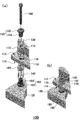
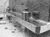
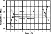
- the shock absorber 100 is shown, (a) is an exploded perspective view, (b) is an assembled perspective view. A cross-sectional view of the shock absorber 100 is shown. It is the photograph which showed the state which assembled the shock absorber 100 partially. It is the photograph which showed the state which assembled the shock absorber 100 partially. 4 is a photograph showing a state in which the shock absorber 100 is assembled. 4 is a photograph showing a state in which the shock absorber 100 is disposed between the first member 110 and the second member 120. It is a graph which shows the stress versus strain characteristic of a copper-aluminum-nickel series single crystal shape memory alloy. It is a graph which shows the result of an impact test, and shows the time response of acceleration with and without the shock absorber 100.
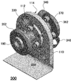
- shock absorber 200 is shown, (a) is an exploded perspective view, (b) is an assembled perspective view. A perspective view of shock absorber 300 is shown.
- FIG. 1 shows a shock absorber 100.
- 1A is an exploded perspective view
- FIG. 1B is an assembled perspective view.
- FIG. 2 shows a cross-sectional view of the shock absorber 100.
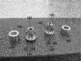
- 3 and 4 are photographs showing a state in which the shock absorber 100 is partially assembled
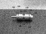
- FIG. 5 is a photograph showing a state in which the shock absorber 100 is assembled.
- FIG. 6 is a photograph showing a state in which the shock absorber 100 is disposed between the first member 110 and the second member 120.
- the shock absorber 100 is a shock absorber that connects the first member 110 and the second member 120 and can be applied to the shock between the first member 110 and the second member 120.
- the second member 120 is a main body (housing) of a device that is difficult to avoid vibrations and impacts applied to the main body, such as an artificial satellite, and the first member 110 is fixed to the main body (housing) such as a precision instrument. And it is a support member of the built-in device which wants to avoid the propagation of vibration and the like from the main body as much as possible. Propagation of vibration or impact applied to the second member 120 to the first member 110 is suppressed by disposing the shock absorber 100 between the second member 120 and the first member 110.
- the shock absorber 100 includes a first shock absorber 130, a second shock absorber 140, and a holding connection mechanism.
- the first cushioning material 130, the second cushioning material 140, and the first member 110 are arranged in the order of the first cushioning material 130, the first member 110, and the second cushioning material 140.
- the first member 110 is held by being sandwiched from the outside of the second buffer material 140. That is, the holding connection mechanism holds the first member 110 via the first buffer material 130 and the second buffer material 140.
- the holding connection mechanism is connected to the second member 120. Therefore, the first member 110 held by the holding connection mechanism is supported by the second member 120 via the holding connection mechanism, and is applied to the second member 120 by the first buffer material 130 and the second buffer material 140. The generated vibration or impact is absorbed, and propagation of vibration or the like to the first member 110 is suppressed.
- the structure of the shock absorber 100 shown in FIGS. 1 and 2 will be described in more detail.
- the first member 110 is a plate member having a first surface 112 and a second surface 114 that is the opposite surface of the first surface 112, and the first member 110 that is the plate member is changed from the first surface 112 to the second surface 114. It has a through-hole 116 that reaches.
- the holding connection mechanism has a first coupler 150 located on the first surface 112 side and a second coupler 160 located on the second surface 114 side.
- the first coupler 150 includes a first holding unit 152 and a first connection unit 154
- the second coupler 160 includes a second holding unit 162 and a second connection unit 164.
- the first holding part 152 holds the first cushioning material 130 between the first member 110, which is a plate material, and the first connecting part 154 is connected to the second coupler 160 through the through hole 116.
- the second holding portion 162 holds the second cushioning material 140 between the first member 110 that is a plate material, and the second connecting portion 164 is connected to the first coupler 150 through the through hole 116.
- the first cushioning material 130 is composed of a plurality of columnar cushioning materials, and the plurality of columnar cushioning materials are movably held in the holes 172 formed in the first collar 170. Since the plurality of columnar cushioning materials are held in the holes 172 of the first collar 170, the first cushioning material 130 is disposed around the first connection portion 154. One end of the columnar first cushioning material 130 is in contact with the bottom surface of the hole 172, and the other end is in contact with the first holding portion 152 of the first coupler 150. By tightening the bolt 190, the first coupler 150 is pressed in the direction of the first member 110 to hold the first member 110, and the first cushioning material 130 receives stress.
- the second cushioning material 140 is composed of a plurality of columnar cushioning materials, and the plurality of columnar cushioning materials are movably held in the holes 182 formed in the second collar 180. By holding the plurality of columnar cushioning materials in the holes 182 of the second collar 180, the second cushioning material 140 is disposed around the second connection portion 164. One end of the columnar second cushioning material 140 abuts on the bottom surface of the hole 182, and the other end abuts on the second holding part 162 of the second coupler 160. By tightening the bolt 190, the second coupler 160 is pressed in the direction of the first member 110 to hold the first member 110, and the second cushioning material 140 receives stress.
- the first cushioning material 130 becomes the first holding portion 152 and the plate material.
- the second cushioning material 140 receives stress between the second holding part 162 and the plate material.
- the further tightening force does not act on the first cushioning material 130 and the second cushioning material 140, and the first cushioning material 130 and The stress which the 2nd shock absorbing material 140 receives is restrict
- the first shock absorbing material 130 and the second shock absorber 100 and the second shock absorber 100 are in a neutral state where no vibration or the like is applied. A certain stress is applied to the buffer material 140.
- a single crystal shape memory alloy may be mentioned. Specifically, a copper / aluminum / nickel-based single crystal shape memory alloy is preferable.
- the single crystal shape memory alloy is preferably austenite at the operating environment temperature and becomes martensite when stress is applied.
- FIG. 7 is a graph showing stress versus strain characteristics of a copper / aluminum / nickel single crystal shape memory alloy.
- the stress-strain characteristic in FIG. 7 shows hysteresis when the stress is increased from 0 to 300 MPa and then decreased until the stress becomes 0 MPa.
- the copper / aluminum / nickel single crystal shape memory alloy is in an austenite state in which the strain increases in proportion to the stress from the O point to the A point, and a little stress is applied from the A point to the B point. It becomes a martensite state which is greatly distorted by the increase.
- point B maximum strain
- the shock absorber 100 uses a shape memory alloy that enters a martensite state when stress is applied as the first shock absorber 130 and the second shock absorber 140. That is, the shock absorber 100 is disposed between the first member 110 and the second member 120, and in the neutral state where vibration or the like is not applied, the first shock absorber 130 and the second shock absorber 140 are in a martensitic state. Stress is applied in advance.
- the stress applied in advance that is, the stress applied to the first buffer material 130 and the second buffer material 140 in a state where the first member 110 is held between the first buffer material 130 and the second buffer material 140 is a single crystal shape memory alloy. Is preferably in the middle of the stress range in the martensitic state. That is, it is preferable that the stress applied in advance is an intermediate value of each stress at points A and D in FIG. 7 or an intermediate value of each stress at points B and C.
- the value of stress applied in advance can be set by adjusting the holding connection mechanism.
- the lengths of the first connecting portion 154 of the first coupler 150 and the second connecting portion 164 of the second coupler 160, and the lengths of the first shock absorbing material 130 and the second shock absorbing material 140 are set as follows.
- the strain of the buffer material 130 and the second buffer material 140 can be about 4.5%, the stress range in the martensite state can be set to the middle.
- a shape memory alloy is used for the first shock absorber 130 and the second shock absorber 140, and stress is applied in advance to bring the shape memory alloy into the martensite state. And good damping characteristics can be obtained while maintaining high strength and rigidity.
- a single crystal shape memory alloy particularly a copper / aluminum / nickel single crystal shape memory alloy is used as the first buffer material 130 and the second buffer material 140
- the strain range in the martensite state is as large as 9%, and the stress of hysteresis Since the range is narrow, even with a small stress change, the amount of strain change is large, and efficient attenuation can be realized. As a result, the device can be easily reduced in weight and size.
- the temperature characteristics of the shock absorber 100 can be stabilized. Further, since the shock absorber 100 can be made entirely of metal, it is possible to obtain a device that does not have to worry about degassing.
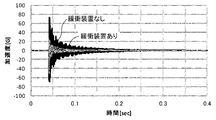
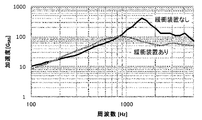
- FIGS. 8 to 10 are graphs showing the results of an impact test in which the vibration state of the first member 110 is tested when an impact is applied to the second member 120.
- FIG. 8 shows the time response of the acceleration of the first member 110.
- FIG. 9 shows the frequency response of the acceleration of the first member 110, and
- FIG. 10 shows the frequency response of the response acceleration of the first member 110 with and without the shock absorber 100, respectively. It can be seen that when the shock absorber 100 is present, the absolute value of acceleration is smaller than when the shock absorber 100 is absent, and both acceleration and response acceleration are reduced in a high frequency region of 1 kHz or higher.
- FIG. 11 is a graph showing the results of the random vibration test, and shows the frequency response of the response magnification with and without the shock absorber 100.
- FIG. It can be seen that when the shock absorber 100 is present, the maximum value of the response magnification is greatly reduced and the peak value is shifted to the low frequency side as compared with the case where the shock absorber 100 is not present.
- the shock absorber 100 can reduce vibration and impact, and in particular, can reduce vibration in a high frequency region of 1 kHz or higher.
- the third buffer material 230 and the fourth buffer material 240 may be configured as in the shock absorber 200 shown in FIG. In FIG. 12, (a) is an exploded perspective view, and (b) is an assembled perspective view.
- the shock absorber 200 eliminates the first collar 170 and the second collar 180 in the shock absorber 100 and applies the third shock absorber 230 and the fourth shock absorber 240 in place of the first shock absorber 130 and the second shock absorber 140. It is.
- the third cushioning material 230 and the fourth cushioning material 240 are cylindrical cushioning materials having a through hole 232 and a through hole 242 between the upper surface and the bottom surface, respectively, and the first connection portion 154 and the second connection portion 164 are The cylindrical buffer material is connected through the through hole 232 and the through hole 242. Also with the shock absorber 200, the same effect as the shock absorber 100 can be obtained.
- the first member 110 is a plate material having a first surface 112 and a second surface 114 opposite to the first surface 112, and the plate material is a first material.
- a through-hole 116 that reaches the second surface 114 from the surface 112 is provided.
- the holding connection mechanism includes a third holding portion 352 arranged on the first surface 112 side, a fourth holding portion 362 arranged on the second surface 114 side, and the third holding portion through the through hole 116.
- the fifth cushioning material 330 and the sixth cushioning material 340 are composed of a plurality of plate-like cushioning materials, each of the plurality of plate-like cushioning materials is bent, one end is fixed to the first member 110, and the other end is third. It is fixed to the holding part 352 or the fourth holding part 362. Thereby, a stress is applied to the plate-like cushioning material.
- the 5th shock absorbing material 330 and the 6th shock absorbing material 340 of the shock absorber 300 are plate-shaped, and are changed to a martensite state by a bending stress.
- the first shock absorber 130 and the second shock absorber 140 of the shock absorber 100 or the third shock absorber 230 and the fourth shock absorber 240 of the shock absorber 200 are different from being transferred to the martensite state by the compressive force.
- the buffer device 300 is superior to the buffer device 100 or the buffer device 200 in buffering in a low frequency region. Other effects are the same as those of the shock absorber 100 or the shock absorber 200.
- SYMBOLS 100 DESCRIPTION OF SYMBOLS 100 ... Shock absorber 110 ... 1st member, 112 ... 1st surface, 114 ... 2nd surface, 116 ... Through-hole, 120 ... 2nd member, 130 ... 1st buffer material, 140 ... 2nd buffer material, 150 ... First coupler 152... First holding portion 154... First connecting portion 160... Second coupler 162. Second holding portion 164. Second connecting portion 170 ... First color 172. 180, second collar, 182, second collar hole, 190, bolt, 192, fitting surface, 200, shock absorber, 230, third cushioning material, 232, through-hole in third cushioning material, 240 4th buffer material, 242 ... 4th buffer material through-hole, 300 ... Buffer device, 330 ... 5th buffer material, 340 ... 6th buffer material, 352 ... 3rd holding part, 362 ... 4th holding part, 370 ... Connection part.
Abstract
Priority Applications (5)
| Application Number | Priority Date | Filing Date | Title |
|---|---|---|---|
| PCT/JP2014/069286 WO2016013054A1 (fr) | 2014-07-22 | 2014-07-22 | Dispositif d'absorption de chocs |
| EP14898062.6A EP3173656B1 (fr) | 2014-07-22 | 2014-07-22 | Dispositif d'absorption de chocs |
| JP2016503034A JP6392845B2 (ja) | 2014-07-22 | 2014-07-22 | 緩衝装置 |
| ES14898062T ES2763100T3 (es) | 2014-07-22 | 2014-07-22 | Dispositivo de absorción de impactos |
| US15/413,148 US10119587B2 (en) | 2014-07-22 | 2017-01-23 | Shock absorbing device |
Applications Claiming Priority (1)
| Application Number | Priority Date | Filing Date | Title |
|---|---|---|---|
| PCT/JP2014/069286 WO2016013054A1 (fr) | 2014-07-22 | 2014-07-22 | Dispositif d'absorption de chocs |
Related Child Applications (1)
| Application Number | Title | Priority Date | Filing Date |
|---|---|---|---|
| US15/413,148 Continuation US10119587B2 (en) | 2014-07-22 | 2017-01-23 | Shock absorbing device |
Publications (1)
| Publication Number | Publication Date |
|---|---|
| WO2016013054A1 true WO2016013054A1 (fr) | 2016-01-28 |
Family
ID=55162612
Family Applications (1)
| Application Number | Title | Priority Date | Filing Date |
|---|---|---|---|
| PCT/JP2014/069286 WO2016013054A1 (fr) | 2014-07-22 | 2014-07-22 | Dispositif d'absorption de chocs |
Country Status (5)
| Country | Link |
|---|---|
| US (1) | US10119587B2 (fr) |
| EP (1) | EP3173656B1 (fr) |
| JP (1) | JP6392845B2 (fr) |
| ES (1) | ES2763100T3 (fr) |
| WO (1) | WO2016013054A1 (fr) |
Cited By (1)
| Publication number | Priority date | Publication date | Assignee | Title |
|---|---|---|---|---|
| WO2020085337A1 (fr) * | 2018-10-23 | 2020-04-30 | 株式会社ウェルリサーチ | Dispositif de propulsion |
Families Citing this family (1)
| Publication number | Priority date | Publication date | Assignee | Title |
|---|---|---|---|---|
| US10655697B2 (en) * | 2016-11-23 | 2020-05-19 | Itt Manufacturing Enterprises Llc | Vibration isolator |
Citations (4)
| Publication number | Priority date | Publication date | Assignee | Title |
|---|---|---|---|---|
| JPH0989045A (ja) * | 1995-09-27 | 1997-03-31 | Nec Eng Ltd | 緩衝支持構造 |
| JP2004334959A (ja) * | 2003-05-06 | 2004-11-25 | Sharp Corp | 記憶装置の緩衝装置 |
| JP2010505078A (ja) * | 2006-09-27 | 2010-02-18 | イリノイ トゥール ワークス インコーポレイティド | ワーク絶縁組立体 |
| JP2011096796A (ja) * | 2009-10-29 | 2011-05-12 | Nec Engineering Ltd | プリント配線基板用緩衝装置 |
Family Cites Families (34)
| Publication number | Priority date | Publication date | Assignee | Title |
|---|---|---|---|---|
| US4401290A (en) * | 1981-03-23 | 1983-08-30 | 4-S Oil Company, Inc. | Stabilized seat |
| US4713714A (en) * | 1985-11-26 | 1987-12-15 | Motorola Computer Systems, Inc. | Computer peripheral shock mount for limiting motion-induced errors |
| JP3525567B2 (ja) * | 1995-07-17 | 2004-05-10 | 東海ゴム工業株式会社 | 筒形防振支持体 |
| US5641153A (en) * | 1995-12-06 | 1997-06-24 | Lord Corporation | Auxiliary damper for rubber suspension mountings |
| US5842677A (en) * | 1996-09-26 | 1998-12-01 | Lord Corporation | Safetied sandwich mount assembly with integral holding and centering feature |
| US5799930A (en) * | 1997-01-30 | 1998-09-01 | Means Industries, Inc. | Body mount assembly |
| DE29710578U1 (de) * | 1997-06-17 | 1997-08-28 | Wolf Woco & Co Franz J | Einknüpflager |
| US6523817B1 (en) * | 1999-04-23 | 2003-02-25 | The Goodyear Tire & Rubber Company | Interlocking vehicle body mount |
| US6820908B1 (en) * | 2000-04-28 | 2004-11-23 | Freundenberg-Nok General Partnership | Isolation mount |
| US6502883B2 (en) * | 2000-12-04 | 2003-01-07 | Cooper Technology Services, Llc | Two stage body mount rebound cushion |
| TW551768U (en) * | 2002-01-18 | 2003-09-01 | Coretronic Corp | Multi-axis adjustment device |
| FR2852371B1 (fr) * | 2003-03-12 | 2006-12-01 | Isolateur de vibrations et/ou de chocs | |
| US7735812B2 (en) * | 2003-04-30 | 2010-06-15 | Trelleborg Ab | Vibration-damping device |
| KR100514891B1 (ko) * | 2003-11-07 | 2005-09-14 | 현대자동차주식회사 | 차량용 롤로드 |
| DE102004019242A1 (de) * | 2004-04-16 | 2005-11-17 | Fraunhofer-Gesellschaft zur Förderung der angewandten Forschung e.V. | Schnittstelle mit Schubableitung zum Dämpfen mechanischer Schwingungen |
| US7503552B2 (en) * | 2004-06-18 | 2009-03-17 | Basf Corporation | Mount assembly |
| TWI260482B (en) * | 2005-02-23 | 2006-08-21 | Asustek Comp Inc | Shockproof locking assembly device |
| US7163200B2 (en) * | 2005-03-09 | 2007-01-16 | Basf Corporation | Interlocking mount assembly for a vehicle |
| US7261365B2 (en) * | 2005-03-09 | 2007-08-28 | Basf Corporation | Vehicle body mount assembly |
| US7416174B2 (en) * | 2005-05-12 | 2008-08-26 | Cooper Standard Automotive | Mount assembly |
| EP1770302A1 (fr) * | 2005-09-30 | 2007-04-04 | Acandis GmbH & Co. KG | Procédé d'amortissement et dispositif correspondant |
| US8226066B2 (en) * | 2007-11-27 | 2012-07-24 | Lord Corporation | Center-bonded isolation mounting assembly |
| DE102007061116A1 (de) * | 2007-12-19 | 2009-06-25 | Robert Bosch Gmbh | Steuergerätegehäuse |
| JP5355901B2 (ja) * | 2008-02-21 | 2013-11-27 | 日立建機株式会社 | 防振支持装置 |
| FR2935769B1 (fr) * | 2008-09-10 | 2016-08-12 | Renault Sas | Articulation elastique de suspension de vehicule automobile et structure de vehicule automobile comportant une telle articulation |
| JP5665774B2 (ja) * | 2010-02-04 | 2015-02-04 | 株式会社ブリヂストン | 防振装置 |
| WO2011156667A1 (fr) * | 2010-06-10 | 2011-12-15 | Grand Rapids Controls Co., Llc | Mât porteur doté d'une boîte à ressort mécanique |
| US8646760B2 (en) * | 2010-06-22 | 2014-02-11 | Honeywell International Inc. | Chassis mounting system |
| JP5290260B2 (ja) * | 2010-10-29 | 2013-09-18 | 東海ゴム工業株式会社 | タンク用ゴムクッション |
| JP5784912B2 (ja) * | 2011-01-06 | 2015-09-24 | 東洋ゴム工業株式会社 | 防振装置 |
| JP5762780B2 (ja) | 2011-03-22 | 2015-08-12 | 日本車輌製造株式会社 | 履歴型ダンパー |
| FR3013684B1 (fr) * | 2013-11-22 | 2017-10-13 | Astrium Sas | Structure porteuse de satellite comportant un dispositif de liaison amortissante |
| DE102014216670B4 (de) * | 2014-08-21 | 2016-05-19 | Ford Global Technologies, Llc | Lagerbuchse |
| US10655697B2 (en) * | 2016-11-23 | 2020-05-19 | Itt Manufacturing Enterprises Llc | Vibration isolator |
-
2014
- 2014-07-22 ES ES14898062T patent/ES2763100T3/es active Active
- 2014-07-22 EP EP14898062.6A patent/EP3173656B1/fr active Active
- 2014-07-22 WO PCT/JP2014/069286 patent/WO2016013054A1/fr active Application Filing
- 2014-07-22 JP JP2016503034A patent/JP6392845B2/ja not_active Expired - Fee Related
-
2017
- 2017-01-23 US US15/413,148 patent/US10119587B2/en active Active
Patent Citations (4)
| Publication number | Priority date | Publication date | Assignee | Title |
|---|---|---|---|---|
| JPH0989045A (ja) * | 1995-09-27 | 1997-03-31 | Nec Eng Ltd | 緩衝支持構造 |
| JP2004334959A (ja) * | 2003-05-06 | 2004-11-25 | Sharp Corp | 記憶装置の緩衝装置 |
| JP2010505078A (ja) * | 2006-09-27 | 2010-02-18 | イリノイ トゥール ワークス インコーポレイティド | ワーク絶縁組立体 |
| JP2011096796A (ja) * | 2009-10-29 | 2011-05-12 | Nec Engineering Ltd | プリント配線基板用緩衝装置 |
Cited By (3)
| Publication number | Priority date | Publication date | Assignee | Title |
|---|---|---|---|---|
| WO2020085337A1 (fr) * | 2018-10-23 | 2020-04-30 | 株式会社ウェルリサーチ | Dispositif de propulsion |
| US11906266B2 (en) | 2018-10-23 | 2024-02-20 | Wel Research Co., Ltd | Propelling device |
| JP7436381B2 (ja) | 2018-10-23 | 2024-02-21 | 株式会社ウェルリサーチ | 射出装置 |
Also Published As
| Publication number | Publication date |
|---|---|
| US10119587B2 (en) | 2018-11-06 |
| US20170152906A1 (en) | 2017-06-01 |
| EP3173656A1 (fr) | 2017-05-31 |
| JPWO2016013054A1 (ja) | 2017-06-22 |
| EP3173656B1 (fr) | 2019-09-25 |
| ES2763100T3 (es) | 2020-05-27 |
| JP6392845B2 (ja) | 2018-09-19 |
| EP3173656A4 (fr) | 2018-04-18 |
Similar Documents
| Publication | Publication Date | Title |
|---|---|---|
| Weber | Semi-active vibration absorber based on real-time controlled MR damper | |
| Carrella et al. | Optimization of a quasi-zero-stiffness isolator | |
| Kalathur et al. | Column dampers with negative stiffness: high damping at small amplitude | |
| US9194452B2 (en) | High stiffness vibration damping apparatus, methods and systems | |
| JP5275230B2 (ja) | ダンパ装置 | |
| JP5587806B2 (ja) | バネ部材 | |
| JP5787142B2 (ja) | バネ部材 | |
| Li et al. | Development and validation of a piecewise linear nonlinear energy sink for vibration suppression and energy harvesting | |
| JP2012189104A (ja) | 慣性質量ダンパー | |
| US10591014B2 (en) | Multi-performance hysteretic rheological device | |
| CN108240415B (zh) | 复合屈曲梁/板负刚度动力吸振器的大载荷高阻尼减振器 | |
| JP6392845B2 (ja) | 緩衝装置 | |
| Morais et al. | Shape memory alloy based dampers for earthquake response mitigation | |
| Choi et al. | Smart damper using the combination of magnetic friction and pre-compressed rubber springs | |
| Lee et al. | A comparison of vibration isolation characteristics of various forms of passive vibration isolator | |
| RU2557865C1 (ru) | Амортизатор с квазинулевой жесткостью | |
| JP2014231897A (ja) | 引張ブレース制振システム | |
| Dykstra et al. | Buckling metamaterials for extreme vibration damping | |
| Du Plooy et al. | The development of a tunable vibration absorbing isolator | |
| CA2989385C (fr) | Attenuateur passif leger pour aeronefs spatiaux | |
| US11841060B1 (en) | Isolation system and method | |
| JP2005207589A (ja) | ダンピングコイルばね及び振動減衰装置 | |
| JP2015117791A (ja) | 振動減衰器及びこれを用いたサスペンション | |
| CN111043213A (zh) | 稳态可控层合压杆及基于该层合压杆的瞬态振动抑制结构 | |
| Abolfathi et al. | Passive vibration isolation using axially loaded curved beams |
Legal Events
| Date | Code | Title | Description |
|---|---|---|---|
| ENP | Entry into the national phase |
Ref document number: 2016503034 Country of ref document: JP Kind code of ref document: A |
|
| 121 | Ep: the epo has been informed by wipo that ep was designated in this application |
Ref document number: 14898062 Country of ref document: EP Kind code of ref document: A1 |
|
| NENP | Non-entry into the national phase |
Ref country code: DE |
|
| REEP | Request for entry into the european phase |
Ref document number: 2014898062 Country of ref document: EP |
|
| WWE | Wipo information: entry into national phase |
Ref document number: 2014898062 Country of ref document: EP |