WO2016009735A1 - 繊維強化熱可塑性樹脂テープの製造装置及び製造方法 - Google Patents
繊維強化熱可塑性樹脂テープの製造装置及び製造方法 Download PDFInfo
- Publication number
- WO2016009735A1 WO2016009735A1 PCT/JP2015/066111 JP2015066111W WO2016009735A1 WO 2016009735 A1 WO2016009735 A1 WO 2016009735A1 JP 2015066111 W JP2015066111 W JP 2015066111W WO 2016009735 A1 WO2016009735 A1 WO 2016009735A1
- Authority
- WO
- WIPO (PCT)
- Prior art keywords
- thermoplastic resin
- nozzle
- fiber
- fiber bundle
- tape
- Prior art date
Links
Images


Classifications
-
- B—PERFORMING OPERATIONS; TRANSPORTING
- B29—WORKING OF PLASTICS; WORKING OF SUBSTANCES IN A PLASTIC STATE IN GENERAL
- B29B—PREPARATION OR PRETREATMENT OF THE MATERIAL TO BE SHAPED; MAKING GRANULES OR PREFORMS; RECOVERY OF PLASTICS OR OTHER CONSTITUENTS OF WASTE MATERIAL CONTAINING PLASTICS
- B29B15/00—Pretreatment of the material to be shaped, not covered by groups B29B7/00 - B29B13/00
- B29B15/08—Pretreatment of the material to be shaped, not covered by groups B29B7/00 - B29B13/00 of reinforcements or fillers
- B29B15/10—Coating or impregnating independently of the moulding or shaping step
- B29B15/12—Coating or impregnating independently of the moulding or shaping step of reinforcements of indefinite length
- B29B15/14—Coating or impregnating independently of the moulding or shaping step of reinforcements of indefinite length of filaments or wires
-
- B—PERFORMING OPERATIONS; TRANSPORTING
- B29—WORKING OF PLASTICS; WORKING OF SUBSTANCES IN A PLASTIC STATE IN GENERAL
- B29C—SHAPING OR JOINING OF PLASTICS; SHAPING OF MATERIAL IN A PLASTIC STATE, NOT OTHERWISE PROVIDED FOR; AFTER-TREATMENT OF THE SHAPED PRODUCTS, e.g. REPAIRING
- B29C70/00—Shaping composites, i.e. plastics material comprising reinforcements, fillers or preformed parts, e.g. inserts
- B29C70/04—Shaping composites, i.e. plastics material comprising reinforcements, fillers or preformed parts, e.g. inserts comprising reinforcements only, e.g. self-reinforcing plastics
- B29C70/06—Fibrous reinforcements only
-
- B—PERFORMING OPERATIONS; TRANSPORTING
- B29—WORKING OF PLASTICS; WORKING OF SUBSTANCES IN A PLASTIC STATE IN GENERAL
- B29C—SHAPING OR JOINING OF PLASTICS; SHAPING OF MATERIAL IN A PLASTIC STATE, NOT OTHERWISE PROVIDED FOR; AFTER-TREATMENT OF THE SHAPED PRODUCTS, e.g. REPAIRING
- B29C70/00—Shaping composites, i.e. plastics material comprising reinforcements, fillers or preformed parts, e.g. inserts
- B29C70/04—Shaping composites, i.e. plastics material comprising reinforcements, fillers or preformed parts, e.g. inserts comprising reinforcements only, e.g. self-reinforcing plastics
- B29C70/28—Shaping operations therefor
- B29C70/40—Shaping or impregnating by compression not applied
- B29C70/50—Shaping or impregnating by compression not applied for producing articles of indefinite length, e.g. prepregs, sheet moulding compounds [SMC] or cross moulding compounds [XMC]
- B29C70/52—Pultrusion, i.e. forming and compressing by continuously pulling through a die
Definitions
- the present invention relates to a manufacturing apparatus and a manufacturing method for a fiber-reinforced thermoplastic resin tape including continuous fibers and a thermoplastic resin impregnated therein.
- Patent Document 1 discloses a carbon fiber reinforced thermoplastic resin tape and a method for producing the same.
- the carbon fiber impregnated with the molten resin is pulled out as a tape through the downstream slit nozzle, and is pulled out from the downstream slit nozzle by the tape cooling means provided downstream of the downstream slit nozzle. Quenching the tape immediately after it at a temperature lowering rate or higher.
- Patent Document 1 describes that in order to prevent deformation of the tape, it is desirable to attach a cooling roller constituting the tape cooling means as close as possible to the downstream slit nozzle.
- the cooling roller is installed at a position where the axial distance between the nozzle roller and the cooling roller is 200 mm downstream of the downstream slit nozzle.
- the produced fiber-reinforced thermoplastic resin tape has a density of fibers in the width direction. It has been found that there are portions where only the thermoplastic resin is present, and defective portions where neither fibers nor thermoplastic resin are present.
- An object of the present invention is to provide an apparatus and a method capable of producing a fiber reinforced thermoplastic resin tape with few defective portions.
- an apparatus for manufacturing a fiber reinforced thermoplastic resin tape a resin impregnating apparatus for impregnating a molten thermoplastic resin into a fiber bundle, wherein the fiber bundle and the fiber impregnated therein are impregnated.
- a resin impregnating apparatus that includes a container for containing the thermoplastic resin, the container having an outlet, and allowing the fiber bundle impregnated with the thermoplastic resin to be discharged through the outlet, and the resin
- a nozzle that is provided at the outlet of the container of the impregnation device and that allows the fiber bundle impregnated with the thermoplastic resin to pass through while being in a tape shape, and is disposed on the downstream side of the nozzle and passes through the nozzle.
- the opening of the nozzle that allows passage of the fiber bundle is a rectangular slit having a long side and a short side.
- T (mm) the dimension of the short side of the tip of the nozzle
- L (mm) the distance between the tip of the nozzle and the contact position
- T and the distance L are as follows: Either (A) or (B) is satisfied.
- a resin impregnation step of impregnating a molten thermoplastic resin into a fiber bundle, and a rectangular slit having a long side and a short side After passing through the nozzle passing step of passing the fiber bundle impregnated with the thermoplastic resin through the resin impregnation step into a tape shape by passing the fiber bundle impregnated with the thermoplastic resin through the resin impregnation step;
- the dimension of the short side of the tip of the nozzle is T (mm), and the distance between the tip of the nozzle and the contact position where the fiber bundle first contacts the main cooling roller is L.
- T and the distance L satisfy one of the following formulas (A) and (B).
- L 1000 ⁇ T-35; T ⁇ 0.08 (A) L ⁇ 785.7 ⁇ T ⁇ 17.9; T ⁇ 0.08 (B)
- FIG. 1 It is a schematic diagram of the manufacturing apparatus of the fiber reinforced thermoplastic resin tape which concerns on the 1st Embodiment of this invention. It is an enlarged view of the feeding machine which concerns on the said 1st Embodiment. It is the cross-sectional front view which expanded the nozzle shown by FIG. It is the figure which looked at the nozzle shown by FIG. 1 from the direction of the arrow 3B of FIG. It is the front view which expanded the modification of the said nozzle. It is the figure which looked at the nozzle shown by FIG. 4A from the direction corresponded to the direction of the arrow 3B of FIG. It is the figure which looked at the grooved roller shown by FIG. 1 from the direction of the said arrow 3B.
- FIG. It is a top view of the resin impregnation apparatus shown by FIG. It is the cross-sectional front view which expanded the nozzle and cooling roller part which are shown by FIG. It is a photograph which shows the external appearance of the fiber reinforced thermoplastic resin tape manufactured with the apparatus shown by FIG. It is a front view which shows the 1st modification of the said resin impregnation apparatus and the said cooling roller part. It is a front view which shows the 2nd modification of the said resin impregnation apparatus and the said cooling roller part. It is the cross-sectional front view which expanded the nozzle and the cooling roller part of the manufacturing apparatus of the fiber reinforced thermoplastic resin tape which concerns on the 2nd Embodiment of this invention.
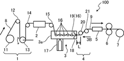
- FIG. 1 shows an apparatus 100 for manufacturing a fiber-reinforced thermoplastic resin tape according to a first embodiment of the present invention.
- the manufacturing apparatus 100 manufactures the fiber reinforced thermoplastic resin tape while transporting the fiber bundle 8 in a predetermined transport direction.
- the manufacturing apparatus 100 includes a feeding machine 1, a fiber preheating machine 2, a resin impregnation apparatus 3, a nozzle 18, a cooling roller unit 4, a cooling unit 5, a take-up machine 6, and a winder 7, which are in the conveying direction. Are arranged in order.
- the feeding machine 1 includes a fiber bobbin 11, a guide bar 12, a dancer roller 13, and a guide roller 14.
- the fiber bobbin 11 is wound with a fiber bundle 8 in which a plurality of fibers, for example, about 12,000 fibers are bundled together.
- the fiber is a carbon fiber.
- the fibers used in the present invention are not limited to carbon fibers, but continuous fibers such as glass fibers, aramid fibers, ceramic fibers, metal fibers, fibers obtained from heterocycle-containing polymers such as polybenzothiazole and polybenzoxazole, and the like. Fibers can be used. Natural plant fibers obtained by spinning discontinuous fibers into yarns can also be used. Further, as the carbon fiber, carbon fiber such as polyacrylonitrile (PAN), petroleum / coal pitch, rayon, and lignin can be used.
- PAN polyacrylonitrile
- rayon rayon
- lignin lignin
- the guide bar 12, the dancer roller 13, and the guide roller 14 are all members that guide the fiber bundle 8, and have a circular cross section.
- the guide bar 12 is fixed so as not to rotate around its central axis, while the dancer roller 13 and the guide roller 14 are arranged so as to rotate around its central axis. Further, the dancer roller 13 is movable in the vertical direction.
- the fiber bundle 8 is fed out from the fiber bobbin 11 and conveyed while being in contact with the guide bar 12, the dancer roller 13, and the guide roller 14, respectively. At this time, a constant tension is applied to the fiber bundle 8. The tension is mainly adjusted by the dancer roller 13.
- the feeding machine 1 has a tension adjusting mechanism 31 that keeps the tension acting on the fiber bundle 8 constant.
- the tension adjusting mechanism 31 has both end portions, one end of which is connected to the shaft of the dancer roller 13, a tension applying weight 33 provided on the rod member 32, and the rod member 32. It has a connected angle detector 34, a motor 35 that rotates the fiber hobbin 11, and a controller 36.
- the dancer roller 13 is applied with a certain downward force corresponding to the gravity acting on the tensioned weight 33.
- the angle detector 34 supports an end of the rod member 32 opposite to an end connected to the shaft of the dancer roller 13 so as to be rotatable about a horizontal axis, and rotates the rod member 32. Detect the angle.
- the motor 35 and the angle detector 34 are electrically connected to the controller 36.
- the controller 36 adjusts the rotational speed of the motor 35 in accordance with the angle detected by the angle detector 34, thereby making the tension of the fiber bundle 8 fed from the fiber bobbin 11 constant.
- the tension of the fiber bundle 8 is controlled to 300 g, for example.
- the traveling speed of the fiber bundle 8 is, for example, 3 m / min.
- the means for making the tension of the fiber bundle 8 fed out from the fiber bobbin 11 constant is not limited to the tension adjusting mechanism 31 described above.
- Those equipped with the one that calculates the diameter of the bundle 8 and operates the powder clutch or the like to adjust the brake torque of the fiber bobbin 11 can make the tension of the fiber bundle 8 constant.
- the fiber for comprising the tape is drawn out from the plurality of fiber bobbins 11.
- each is a plurality of feeding machines corresponding to the feeding machine 1, and the plurality of feeding machines are arranged in parallel with each other.
- the fiber bundle 8 fed from the feeder 1 is sent to the fiber preheater 2.
- the fiber preheater 2 heats the fiber bundle 8 to about 100 ° C., thereby softening the sizing agent adhering to the fiber bundle 8.
- the sizing agent converges a plurality of fibers to facilitate handling. This softening of the sizing agent facilitates the opening of the fiber bundle 8 and the impregnation of the fiber bundle 8 with the thermoplastic resin in the next step.
- a well-known thing can be used for the fiber preheater 2.
- the fiber bundle 8 carried out from the fiber preheater 2 is sent to the resin impregnation apparatus 3 through the guide roller 15.
- the guide roller 15 has a circular cross section and rotates around its central axis. Instead of the guide roller 15, a guide bar having a circular cross section but not rotating around its central axis may be used.
- the resin impregnation device 3 is for opening the fiber bundle 8 and impregnating the fiber bundle 8 with a molten thermoplastic resin.
- the resin impregnation apparatus 3 includes a container 3a, an extruder 17, and a plurality of impregnation rollers 16.
- the container 3a has a long cylindrical shape in the transport direction of the fiber bundle 8, and stores the molten thermoplastic resin in the container 3a.
- the temperature of the molten thermoplastic resin in the container 3a is, for example, 230 ° C.
- the said container 3a has an exit part, and accept
- the extruder 17 supplies a molten thermoplastic resin into the container 3a.
- This thermoplastic resin has a suitable MFR.
- This MFR is a flowability index (melt flow rate) of the synthetic resin, and is set to an arbitrary value within a range of 30 to 115 [g / 10 minutes], for example.
- the thermoplastic resin is polypropylene.
- the thermoplastic resin used in the present invention is not limited to polypropylene.
- the thermoplastic resin include acrylonitrile-butadiene-styrene copolymer (ABS), polyamide (nylon 6, nylon 66, etc.), polyacetal, polycarbonate, high density polyethylene, low density polyethylene, linear low density polyethylene, polyethylene.
- ABS acrylonitrile-butadiene-styrene copolymer
- polyamide nylon 6, nylon 66, etc.
- polyacetal polycarbonate
- high density polyethylene low density polyethylene
- linear low density polyethylene polyethylene
- Terephthalate, polybutylene terephthalate, polyetherimide, polystyrene, polyethersulfone, polyphenylene sulfide, polyetherketone, polyetheretherketone, and the like can be used.
- Each of the plurality of impregnation rollers 16 is an impregnation member disposed in the container 3a. These impregnation rollers 16 are arranged at predetermined intervals along the transport direction of the fiber bundle 8. The intervals between the impregnating rollers 16 are not limited to equal intervals.
- Each impregnation roller 16 has a circular cross section, and rotates around its central axis, thereby conveying the fiber bundle 8 to the downstream side in the conveying direction while contacting the fiber bundle 8. At least a part of the plurality of impregnation rollers 16 may be a guide bar that has a circular cross section but does not rotate around its central axis.
- the fiber bundle 8 passes through the container 3a in a zigzag manner while contacting the plurality of impregnating rollers 16 in the container 3a for storing the molten thermoplastic resin. That is, the fiber bundle 8 passes through the container 3a in the transport direction while alternately making contact with the lower surface of the specific impregnation roller 16 and contact with the upper surface of the subsequent impregnation roller 16. During the passage, each of the impregnating rollers 16 opens the fiber bundle 8, and the melted thermoplastic resin is impregnated in the opened fiber bundle 8.
- the number of the impregnating rollers 16 is adjusted according to how the fiber bundle 8 is opened and how the thermoplastic resin is impregnated into the fiber bundle 8.
- the number of impregnating rollers 16 is too large, the fiber bundle 8 is excessively opened, and the fiber density at both ends in the width direction of the fiber bundle 8 is increased. Furthermore, when the number of impregnating rollers 16 is too large, excessive tension acts on the fiber bundle 8 to easily cause fiber breakage.
- the number of impregnation rollers 16 is too small, the fiber bundle 8 is not sufficiently opened, and the fiber density is increased at the center in the width direction of the fiber bundle 8, or the thermoplastic resin to the fiber bundle 8 is used. The impregnation of is insufficient.
- the nozzle 18 is provided at the outlet of the container 3a.
- the nozzle 18 allows passage of the fiber bundle 8 discharged from the container 3a while shaping the shape.
- the nozzle 18 has an opening, which is a rectangular slit s having a long side and a short side. Therefore, the fiber bundle 8 that has passed through the nozzle 18 has a flat tape shape. That is, the nozzle 18 allows the fiber bundle 8 impregnated with the thermoplastic resin to pass therethrough while forming a tape shape.
- the fiber bundle 8 impregnated with the thermoplastic resin and passed through the nozzle 18 is referred to as a tape 9.
- the temperature of the nozzle 18 is 230 ° C., for example.
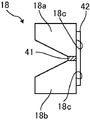
- FIG. 3A is an enlarged view of the nozzle 18, and FIG. 3B is a view of the nozzle 18 seen from the direction of the arrow 3B in FIG.
- the nozzle 18 has a pair of nozzle members 18a and 18b.
- the pair of nozzle members 18a and 18b have surfaces that are aligned vertically and face each other vertically.
- the tip-side portion that is, the tip-side inner surface 18 c of the nozzle member 18 a and the tip-side inner surface 18 c of the nozzle member 18 b have normals orthogonal to the direction in which the fiber bundle 8 is conveyed.
- the nozzle 18 according to the first embodiment further includes a pair of left and right shims 41 and a pair of left and right guide plates 42.
- the pair of shims 41 are sandwiched between the left and right ends of the nozzle member 18a and the left and right ends of the nozzle member 18b, respectively, and thereby, between the inner surfaces 18c and 18c on the tip side of the nozzle members 18a and 18b.
- the size of the vertical gap is defined. This dimension corresponds to the dimension T of the short side of the rectangle constituting the slit s.
- the pair of shims 41 enables a rectangular slit s having a short diameter of the dimension T to be formed between the nozzle members 18a and 18b.
- the fiber bundle 8 passes through the slit s to produce a fiber-reinforced thermoplastic resin tape, and the thickness thereof is the thickness of the slit s that is the opening at the tip of the nozzle 18, that is, the dimension T of the short side of the opening. Be controlled.
- the pair of guide plates 42 are arranged at the tip of the nozzle 18 so as to prevent the shim 41 from contacting the fiber bundle 8 passing through the nozzle 18.
- the pair of guide plates 42 are attached to the opening portion at the tip of the nozzle 18 with screws or the like.
- the pair of guide plates 42 are disposed with a gap W between the pair of guide plates 42.
- the interval W is a dimension corresponding to the width of the fiber-reinforced thermoplastic resin tape to be manufactured, and corresponds to the dimension of the long side of the rectangle constituting the slit S.
- the said fiber bundle 8 is shaped so that the width
- the interval W between the pair of guide plates 42 that is, the width of the fiber-reinforced thermoplastic resin tape to be manufactured is 15 mm.
- the specific dimension of this interval W is not limited.
- the dimension T and the interval W, that is, the thickness and width of the fiber-reinforced thermoplastic resin tape to be manufactured can be easily changed by replacing the shim 41 or changing the positions of the pair of guide plates 42.
- FIGS. 4A and 4B are enlarged views showing a modification of the nozzle 18.
- a groove 18d that defines a slit s may be formed in at least one of the pair of nozzle members 18a and 18b, or in FIG. 4A and FIG. 4B, the nozzle member 18a.
- This configuration eliminates the need for the pair of shims 41 and the pair of guide plates 42 and enables the number of parts to be reduced.
- variety and thickness of the fiber reinforced thermoplastic resin tape to manufacture can be easily changed by replacement
- the impregnating roller 16 on the side close to the nozzle 18 is a grooved roller 19 provided with a groove 19a as shown in FIG.
- this embodiment includes one grooved roller 19, two or more grooved rollers may be provided near the nozzle 18.
- the guide bar may have a groove.
- FIG. 5 is a view of the grooved roller 19 as seen from the direction of the arrow 3B in FIG.
- the groove 19a is provided in the center of the grooved roller 19 in the axial direction, and the interval W between the pair of guide plates 42, that is, the width of the fiber-reinforced thermoplastic resin tape to be manufactured. , Have the same width.
- the fiber bundle 18 is conveyed so as to pass through the groove 19a. In this way, the grooved roller 19 prevents the width of the fiber bundle 8 to be opened from becoming larger than the target width of the fiber-reinforced thermoplastic resin tape to be manufactured.
- the impregnation roller 16 upstream of the grooved roller 19 may be a flat roller without a groove. Conversely, all of the impregnation rollers 16 may be grooved rollers 19.
- FIG. 6 which is a plan view of the resin impregnation apparatus 3, the center of the fiber bundle 8, the center of the nozzle 18, and the center of the grooved roller 19 are mutually coincident. The coincidence between these centers makes it possible to suppress the occurrence of bias in the density of the fibers in the fiber-reinforced thermoplastic resin tape to be produced.
- FIG. 6 also shows a main cooling roller 20 described later together with the resin impregnation apparatus 3.
- the cooling roller unit 4 includes a main cooling roller 20 and a sub cooling roller 21 that are arranged in order from the upstream to the downstream in the transport direction of the tape 9.
- the main cooling roller 20 and the sub cooling roller 21 have a circular cross section and rotate around the central axis. Cooling water is supplied to the main cooling roller 20 and the sub cooling roller 21 through a rotary join rod (not shown), and the cooling water sets the temperature of the main cooling roller 20 and the sub cooling roller 21 to a constant temperature (for example, 20 ° C.). Hold back and forth).
- the main cooling roller 20 is disposed immediately downstream of the nozzle 18, contacts the tape 9 at a predetermined contact position, and cools the tape 9 while feeding the tape 9 downstream.
- the sub-cooling roller 21 is disposed on the downstream side of the main cooling roller 20, and cools while feeding the tape 9 further downstream.
- the tape 9 is in surface contact with the main cooling roller 20 and the cooling roller 21 with a predetermined contact area.
- the temperature of the tape 9 that has passed through the nozzle 18 is equal to or higher than the melting point of the thermoplastic resin. Therefore, in the tape 9 immediately after passing through the nozzle 18, the thermoplastic resin is not solidified, and there is a tendency for the fibers to become dense and dense in the width direction during conveyance. Therefore, in this apparatus, the main cooling roller 20 is arranged so that the tape 9 immediately after passing through the nozzle 18 is first rapidly cooled by the main cooling roller 20.
- the main cooling roller 20 according to the first embodiment cools the upper surface shown in FIG. 1 which is the front surface of the tape 9. Further, the tape 9 is cooled by the sub cooling roller 21 on the downstream side.
- the sub cooling roller 21 cools the lower surface of the tape 9 as shown in FIG.
- thermoplastic resin contained in the tape 9 is solidified before the fibers are densely and densely formed in the width direction of the tape 9.
- the sub-cooling roller 21 is disposed at a position where the uneven cooling generated in the thickness direction of the tape 9 prevents the tape 9 from causing “warping”.
- FIG. 7 is an enlarged view of the nozzle 18 and the cooling roller unit 4.
- the distance L shown in FIG. 7, that is, the distance L between the tip of the nozzle 18 and the contact position, that is, the position where the main cooling roller 20 and the tape 9 are in contact, is the opening at the tip of the nozzle 18.
- T width of the slit s shown in FIG. 3B
- the dimension T (mm) and the distance L (mm) are set so as to satisfy one of the following formula (A) and the following formula (B).
- the contact position is the end point of the distance L when the tip of the nozzle 18 is the starting point, and the position where the tape 9 that has exited the nozzle 18 first contacts the main cooling roller 20.
- the main cooling roller 20 and the tape 9 are in surface contact with each other at a predetermined contact area in this position and in a specific region downstream thereof. That is, the contact position is the position of the upstream end of the region where the tape 9 and the main cooling roller 20 are in contact.
- the rapid cooling by the main cooling roller 20 of the tape 9 immediately after passing through the nozzle 18 solidifies the thermoplastic resin before the fibers become dense and the fibers 9 are densely and densely formed in the width direction of the tape 9. Suppresses the occurrence.
- the distance L between the tip of the nozzle 18 and the contact position where the fiber bundle 8 comes into contact with the main cooling roller 20 for the first time is preferably set to 5 mm or more.
- the main cooling roller 20 has a certain amount. It must have a large diameter. From this point of view, the distance L is preferably set to 5 mm or more.
- the peripheral speed of the cooling roller 20 is set to be higher than the traveling speed of the tape 9 (fiber bundle 8 that has passed through the nozzle 18).
- the peripheral speed of the main cooling roller 20 is set to a speed not less than 1.5 times and not more than 2.0 times the running speed of the tape 9.
- thermoplastic resin adhering to the surface of the main cooling roller 20 may cause partial unevenness on the surface of the tape 9 and reduce the smoothness of the surface of the tape 9.
- FIG. 8 is a photograph showing the appearance of the manufactured fiber reinforced thermoplastic resin tape.
- the lower one has a smooth surface, whereas the upper one has partial irregularities at the locations indicated by the arrows on the surface. Yes.
- a roller driving unit such as a motor 25 for rotating the main cooling roller 20 as shown in FIG. 6 is provided, and the peripheral speed of the main cooling roller 20 is caused to run on the tape 9 by this roller driving unit. It is effective to make it higher than the speed. As a result, a phenomenon in which a part of the molten thermoplastic resin adheres to the surface of the main cooling roller 20 can be suppressed.
- the peripheral speed of the main cooling roller 20 may be a speed at which slip occurs between the tape 9 and the main cooling roller 20. In consideration of the lifetime of the parts of the apparatus, the peripheral speed of the main cooling roller 20 is 1.5 times or more and 2.0 times the running speed of the tape 9, that is, the fiber bundle 8 that has passed through the nozzle 18, as described above. The following is desirable.
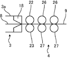
- FIG. 9 is an enlarged view of a first modification of the resin impregnation apparatus 3 and the cooling roller unit 4.
- a pair of main cooling rollers 22 and 23 arranged so as to sandwich the tape 9 may be provided instead of the single main cooling roller 20, a pair of main cooling rollers 22 and 23 arranged so as to sandwich the tape 9 may be provided. Further, at least one pair (two pairs arranged in the transport direction of the tape 9 in FIG. 9) of sub cooling rollers 26 and 27 is provided as a sub cooling roller provided downstream of the pair of main cooling rollers 22 and 23. Also good.
- the pair of main cooling rollers 22 and 23 can simultaneously cool the front surface and the back surface of the tape 9, thereby preventing any one of the front and back surfaces from being biased and cooling. The occurrence of warping of the tape 9 due to this can be effectively suppressed.
- FIG. 10 shows a second modification of the resin impregnation apparatus 3 and the cooling roller unit 4.
- a single main cooling roller 24 and at least one sub-cooling roller 28 (three in FIG. 10 aligned in the transport direction of the tape 9) are aligned in the transport direction. It may be conveyed zigzag while contacting each of these cooling rollers 24, 28,. That is, the tape 9 is cooled by the contact between the surface of the tape 9 and the main cooling roller 24 and the even-numbered sub-cooling roller 28, and the contact between the back surface of the tape 9 and the odd-numbered sub-cooling roller 28. It may be conveyed downstream while alternately receiving the cooling of the back surface.
- the total contact area between the plurality of cooling rollers 24 and 28 and the tape 9 is larger than the total contact area between the main cooling roller 20 and the sub cooling roller 21 and the tape 9 shown in FIG. Since it is wide, the tape 9 can be cooled more efficiently.
- the tape 9 thus cooled by the cooling roller unit 4 is sent to the cooling unit 5 shown in FIG.
- the cooling unit 5 cools the tape 9 with water.
- the cooling unit 5 is a water-cooled pool, for example.
- the cooling unit 5 may cool the tape 9 with air. Moreover, if the cooling by the cooling roller unit 4 is sufficient, the cooling unit 5 may be omitted.
- the tape 9 cooled by the cooling unit 5 is sent to the take-up machine 6 shown in FIG.
- the take-up machine 6 takes up the cooled tape 9.
- the winder 7 winds up the tape 9 taken up by the take-up machine 6. Note that the take-up machine 6 causes the tape 9 and thus the fiber bundle 8 to travel at a predetermined speed.
- the winder 7 can also have the function of the take-up machine 6, that is, the function of taking the tape 9 and running the tape 9 at a predetermined speed.
- the distance L between the tip of the nozzle 18 and the contact position where the main cooling roller 20 and the tape 9 first contact each other is the distance L of the opening at the tip of the nozzle 18.
- it is set so as to satisfy either one of the expressions (A) and (B). That is, in the tape 9 immediately after passing through the nozzle 18, the thermoplastic resin is not solidified, and there is a tendency for the fibers to become dense and dense in the width direction during transportation.
- the formula (A) or (B) The main cooling roller 20 arranged so as to satisfy the equation can rapidly cool the tape 9 immediately after passing through the nozzle 18 to solidify the thermoplastic resin before fiber density occurs in the width direction of the tape 9. This can reduce the density of fibers in the width direction of the tape 9.
- the distance L between the tip of the nozzle 18 and the position where the main cooling roller 20 and the tape 9 are in contact is the dimension of the short side of the opening at the tip of the nozzle 18 (the width of the slit s shown in FIG. 3B) T.
- T the dimension of the short side of the opening at the tip of the nozzle 18 (the width of the slit s shown in FIG. 3B) T.
- the arrangement of at least one sub cooling roller 21 in addition to the main cooling roller 20 enables the tape 9 to be cooled more sufficiently. Further, cooling of only one of the front surface and the back surface of the tape 9 by only a single main cooling roller may cause warpage of the tape 9, whereas the tape 9 by the main and sub cooling rollers 20 and 21 is used. The cooling of the front and back surfaces of the tape 9 makes it possible to effectively suppress warping of the tape 9.
- the resin impregnation apparatus 3 includes a plurality of impregnation members, and at least the impregnation member closest to the nozzle 18 among these impregnation members is the grooved roller 19 as described above, and the grooves Having the groove 19a having the same width as that of the fiber reinforced thermoplastic resin tape from which the attaching roller 19 is manufactured and allowing the fiber bundle 8 to pass through the groove 19a is opened. It is possible to prevent the width of the fiber bundle 8 from becoming larger than the width of the fiber-reinforced thermoplastic resin tape to be manufactured. This allows the production of fiber reinforced thermoplastic tapes with the desired width.
- the nozzle 18 includes a pair of guide plates 42 that are attached at an interval of the same size as the width of the fiber reinforced thermoplastic resin tape to be manufactured at the opening at the tip thereof.
- the pair of guide plates 42 facilitates matching the target width of the fiber-reinforced thermoplastic resin tape that manufactures the width of the fiber bundle 8 that passes through the opening of the nozzle 18. That is, it is possible to easily manufacture a fiber-reinforced thermoplastic resin tape having a desired width. Even if the fiber density of the fiber bundle 8 passing through the opening of the nozzle 18 is generated in the width direction, the width of the fiber bundle 8 is shaped, and at the same time, the fiber density is made uniform in the width direction. . Thereby, a fiber can be uniformly distributed in the width direction of the fiber reinforced thermoplastic resin tape manufactured.
- keeping the tension acting on the fiber bundle 8 constant enhances the effect of suppressing the density of the fibers. If the tension acting on the fiber bundle 8 greatly fluctuates in the container 3a of the resin impregnation apparatus 3, the fiber bundle 8 becomes unstable and the fibers are densely and densely formed in the width direction. On the other hand, keeping the tension acting on the fiber bundle 8 constant enables the fiber bundle 8 to be stably opened, thereby reducing the occurrence of fiber density in the width direction. be able to. Therefore, the fibers can be uniformly distributed in the width direction of the fiber-reinforced thermoplastic resin tape to be manufactured. In addition, keeping the tension acting on the fiber bundle 8 constant also allows the fiber bundle 8 to move straight forward stably.
- the peripheral speed of the main cooling roller 20 is higher than the traveling speed of the tape 9 (fiber bundle 8 that has passed through the nozzles 18), preferably 1.5 times to 2.0 times the traveling speed of the tape 9. This prevents the phenomenon that a part of the molten thermoplastic resin adheres to the surface of the main cooling roller 20, thereby making it possible to manufacture a fiber-reinforced thermoplastic resin tape having a smooth surface.
- FIG. 11 is an enlarged view of the nozzle 18 and the cooling roller unit 4 according to the second embodiment of the present invention.
- the nozzle 18 according to this embodiment has a shape in which the dimension in the direction parallel to the minor axis of the opening decreases toward the main cooling roller 20, that is, a tapered shape.
- This shape allows a part of the main cooling roller 20 to be arranged upstream of the tip of the nozzle 18. That is, the main cooling roller is located at a position where the distance L between the tip of the nozzle 18 and the contact position where the main cooling roller 20 and the tape 9 first contact each other is smaller than the radius R of the main cooling roller 20. 20 can be arranged.
- the distance L between the tip of the nozzle 18 and the contact position between the cooling roller 20 and the tape 9 is smaller than the radius R of the cooling roller 20.
- the main cooling roller 20 is disposed at the position. Further, the shape makes it possible to increase the radius R of the main cooling roller 20 while making the distance L smaller than the radius R of the main cooling roller 20. This makes it possible to cool the tape 9 immediately after passing through the nozzle 18 more rapidly. Moreover, since the radius R of the cooling roller 20 can be increased while having such an arrangement, the size of the cooling roller 20 can be increased. Thereby, since the cooling capacity of the cooling roller 20 increases, the tape 9 can be cooled efficiently.
- the inventors of the present invention manufactured a fiber-reinforced thermoplastic resin tape with different parameters, and have a defective portion free of thermoplastic resin or carbon fiber (hereinafter referred to as a defective portion).
- the test which evaluates the presence or absence of was conducted.
- a bundle of 12,000 carbon fiber trading cards T300 manufactured by Toray was used as the fiber bundle 8.
- polypropylene was used as the thermoplastic resin.
- the traveling speed of the fiber bundle 8 was 3 m / min.
- a distance L [mm] (hereinafter referred to as a distance L) between the tip of the nozzle 18 and a position where the cooling roller 20 and the tape 9 are in contact with each other, and a slit s corresponding to the thickness of the fiber reinforced thermoplastic resin tape to be manufactured.
- the thickness of the fiber-reinforced thermoplastic resin tape to be manufactured is the same as the dimension T (see FIG. 3B) of the short side of the opening at the tip of the nozzle 18 (hereinafter, the thickness of the tape is also referred to as the thickness T). May be indicated.)
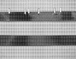
- FIG. 12 is a photograph showing the appearance of the manufactured fiber reinforced thermoplastic resin tape.
- the width of the fiber reinforced thermoplastic resin tape is 15 mm
- the black part is the carbon fiber
- the white part is the part without the carbon fiber, that is, the defective part.
- the upper side has no white part and the lower side has a white part.
- FIG. 13 and FIG. 8 is a photograph showing a cross section of FIG.
- FIG. 13 it can be seen that there is a defective portion without the thermoplastic resin and the carbon fiber.
- FIG. 14 it can be seen that there is a defective portion without the thermoplastic resin.
- FIG. 1 is a photograph showing a cross section of 1.
- FIG. 15 it can be seen that the thermoplastic resin and the carbon fibers are uniformly distributed.
- FIG. 16 shows another comprehensive result when the fiber reinforced thermoplastic resin tape having a width of 15 mm is manufactured as described above.
- FIG. 16 shows the relationship between the dimension T of the short side of the opening at the tip of the nozzle 18 and the distance L between the position where the cooling roller 20 and the tape 9 are in contact with the tip of the nozzle 18.
- the thickness of the manufactured fiber reinforced thermoplastic resin tape is assumed to be the same as the dimension T (see FIG. 3B) of the short side of the opening at the tip of the nozzle 18, and this is expressed as the thickness T.
- “ ⁇ ” indicates that no defect portion without carbon fiber occurred.
- “x” indicates that a defect portion having no carbon fiber is generated.
- the resin impregnation apparatus 3 has a function of opening the fiber bundle 8, but the present invention is not limited to this.
- an opening machine disposed upstream of the resin impregnation apparatus 3, more specifically, between the fiber preheating machine 2 and the resin impregnation apparatus 3, and the opening machine opens the fiber bundle 8.
- the already opened fiber bundle may be wound around the fiber bobbin 11 and the opened fiber bundle 8 may be fed out from the feeder 1.
- an apparatus and a method capable of producing a fiber reinforced thermoplastic resin tape with few defective portions are provided.
- an apparatus for manufacturing a fiber reinforced thermoplastic resin tape a resin impregnating apparatus for impregnating a molten thermoplastic resin into a fiber bundle, wherein the fiber bundle and the fiber impregnated therein are impregnated.
- a resin impregnating apparatus that includes a container for containing the thermoplastic resin, the container having an outlet, and allowing the fiber bundle impregnated with the thermoplastic resin to be discharged through the outlet, and the resin
- a nozzle that is provided at the outlet of the container of the impregnation device and that allows the fiber bundle impregnated with the thermoplastic resin to pass through while being in a tape shape, and is disposed on the downstream side of the nozzle and passes through the nozzle.
- the opening of the nozzle that allows passage of the fiber bundle is a rectangular slit having a long side and a short side.
- T (mm) the dimension of the short side of the tip of the nozzle
- L (mm) the distance between the tip of the nozzle and the contact position
- T and the distance L are as follows: Either (A) or (B) is satisfied.
- the main cooling roller is arranged so that the distance L satisfies the expression (A) or (B). It allows for rapid cooling and allows the thermoplastic resin to solidify before fiber density occurs in the width direction of the tape. This suppresses the occurrence of fiber density in the tape width direction.
- the distance L (mm) is preferably set to 5 mm or more.
- the nozzle has a tapered shape in which the dimension of the nozzle in a direction parallel to the short side decreases toward the at least one main cooling roller, and the tip of the nozzle and the contact position It is preferable that the main cooling roller is disposed at a position where the distance is smaller than the radius of the main cooling roller.
- the shape of the nozzle allows a part of the main cooling roller to be arranged upstream of the tip of the nozzle, thereby reducing the distance L to be smaller than the radius R of the main cooling roller. It is possible to increase the radius R of the main cooling roller. This makes it possible to increase the cooling capacity by increasing the size of the main cooling roller while reducing the distance L.
- the at least one main cooling roller includes a pair of main cooling rollers disposed on both sides of the tape-shaped fiber bundle, and the pair of main cooling rollers are in contact with both surfaces of the fiber bundle.
- the fiber bundle may be cooled.
- the pair of main cooling rollers can effectively suppress the warpage of the tape due to the fact that one of the surfaces is biased by simultaneously cooling both surfaces of the fiber bundle.
- the apparatus may further include at least one sub-cooling roller disposed downstream of the at least one main cooling roller and transporting the fiber bundle while cooling.
- the resin impregnation apparatus further includes a plurality of impregnation members disposed in the container, and each impregnation member has a circular cross section and contacts the fiber bundle, and the plurality of impregnation members
- the impregnation member including at least the impregnation member closest to the nozzle has a groove having a width in a direction parallel to the width of the fiber-reinforced thermoplastic resin tape to be manufactured, and the fiber bundle is in the groove. It is preferable to allow it to pass.
- the impregnating member having the groove makes it possible to prevent the width of the opened fiber bundle from becoming larger than the width of the fiber reinforced thermoplastic resin tape to be manufactured, thereby reinforcing the fiber reinforced with a desired width. Allows the production of thermoplastic tape.
- the nozzle includes a nozzle member that defines the dimension of the opening in the minor axis direction, and a pair of guide plates that are attached to the tip of the nozzle member at an interval that defines the dimension of the opening in the major axis direction. Those are preferred.
- the major axis and minor axis of the opening can be easily adjusted by exchanging the nozzle member or changing the positions of the pair of guide plates.
- the device further includes a tension adjusting mechanism that maintains a constant tension acting on the fiber bundle.
- This tension adjusting mechanism enhances the effect of suppressing the density of the fibers by keeping the tension constant.
- the apparatus is configured so that the peripheral speed of the main cooling roller is higher than the traveling speed of the fiber bundle, more preferably 1.5 times or more and 2.0 times or less of the traveling speed. It is preferable to further include a roller driving unit that rotates the roller.
- the roller driving unit prevents the thermoplastic resin contained in the fiber bundle from adhering to the main cooling roller by slipping the main cooling roller with respect to the fiber bundle, and thereby, It makes it possible to produce a fiber-reinforced thermoplastic resin tape with a smooth surface.
- a resin impregnation step of impregnating a molten thermoplastic resin into a fiber bundle, and a rectangular slit having a long side and a short side After passing through the nozzle passing step of passing the fiber bundle impregnated with the thermoplastic resin through the resin impregnation step into a tape shape by passing the fiber bundle impregnated with the thermoplastic resin through the resin impregnation step;
- the dimension of the short side of the tip of the nozzle is T (mm), and the distance between the tip of the nozzle and the contact position where the fiber bundle first contacts the main cooling roller is L.
- T and the distance L satisfy one of the following formulas (A) and (B).
- L 1000 ⁇ T-35; T ⁇ 0.08 (A) L ⁇ 785.7 ⁇ T ⁇ 17.9; T ⁇ 0.08 (B)
- the main cooling roller has a main speed so that the peripheral speed of the main cooling roller is higher than the traveling speed of the fiber bundle, and more preferably 1.5 to 2.0 times the traveling speed. It is preferable to rotate the cooling roller.
Abstract
Description
L≦1000×T-35;T<0.08・・・(A)
L≦785.7×T-17.9;T≧0.08・・・(B)
L≦1000×T-35;T<0.08・・・(A)
L≦785.7×T-17.9;T≧0.08・・・(B)
L≦1000×T-35;T<0.08・・・(A)
L≦785.7×T-17.9;T≧0.08)・・・(B)

L≦1000×T-35 ・・・(A)
L≦785.7×T-17.9 ・・・(B)
L≦1000×T-35;T<0.08・・・(A)
L≦785.7×T-17.9;T≧0.08・・・(B)
L≦1000×T-35;T<0.08・・・(A)
L≦785.7×T-17.9;T≧0.08・・・(B)
Claims (12)
- 繊維強化熱可塑性樹脂テープを製造するための装置であって、
溶融した熱可塑性樹脂を繊維束に含浸させるための樹脂含浸装置であって、前記繊維束及びこれに含浸される前記熱可塑性樹脂を収容する容器を含み、当該容器が出口部を有してこの出口部を通じて前記熱可塑性樹脂を含浸した前記繊維束が排出されるのを許容する樹脂含浸装置と、
前記樹脂含浸装置の前記容器の前記出口部に設けられ、前記熱可塑性樹脂を含浸した前記繊維束をテープ形状にしながら当該繊維束の通過を許容するノズルと、
前記ノズルの下流側に配置され、前記ノズルを通過した前記テープ形状の繊維束と接触しながら当該繊維束を下流側に送りかつ冷却する少なくとも一つのメイン冷却ローラとを、備え、
前記繊維束の通過を許容する前記ノズルの開口は長辺と短辺とを有する長方形のスリットであり、
前記ノズルの先端の前記短辺の寸法をT(mm)、前記ノズルの先端と、前記繊維束が前記ノズルを出てから前記メイン冷却ローラと最初に接触する接触位置と、の距離をL(mm)としたとき、当該寸法T及び当該距離Lが、下記の(A)式及び(B)式
L≦1000×T-35;T<0.08・・・(A)
L≦785.7×T-17.9;T≧0.08 ・・・(B)
のいずれか一方を満たす、繊維強化熱可塑性樹脂テープの製造装置。 - 請求項1に記載の繊維強化熱可塑性樹脂テープの製造装置であって、前記ノズルは前記短辺と平行な方向についての当該ノズルの寸法が前記少なくとも一つのメイン冷却ローラに向かうに従って小さくなる先細りの形状を有し、前記ノズルの先端と前記接触位置との距離が前記メイン冷却ローラの半径よりも小さくなる位置に前記メイン冷却ローラが配置されている、繊維強化熱可塑性樹脂テープの製造装置。
- 請求項1記載の繊維強化熱可塑性樹脂テープの製造装置であって、前記少なくとも一つのメイン冷却ローラは、前記テープ形状の前記繊維束を挟んでその両側に配置される一対のメイン冷却ローラを含み、当該一対のメイン冷却ローラは前記繊維束の両面にそれぞれ接触しながら当該繊維束を冷却する、繊維強化熱可塑性樹脂テープの製造装置。
- 請求項1に記載の繊維強化熱可塑性樹脂テープの製造装置であって、前記少なくとも一つのメイン冷却ローラの下流側に配置されて前記繊維束を冷却しながら搬送する少なくとも一つのサブ冷却ローラをさらに備える、繊維強化熱可塑性樹脂テープの製造装置。
- 請求項1に記載の繊維強化熱可塑性樹脂テープの製造装置であって、前記樹脂含浸装置は、前記容器の中に配置された複数の含浸用部材をさらに有し、各含浸用部材は円形の断面を有して前記繊維束に接触し、当該複数の前記含浸用部材のうち少なくとも前記ノズルに最も近い含浸用部材を含む含浸用部材は、製造される繊維強化熱可塑性樹脂テープの幅と平行な方向の幅をもつ溝を有し、当該溝内を前記繊維束が通過することを許容する、繊維強化熱可塑性樹脂テープの製造装置。
- 請求項1に記載の繊維強化熱可塑性樹脂テープの製造装置であって、前記ノズルは、前記開口の短径方向の寸法を規定するノズル部材と、前記開口の長径方向の寸法を規定する間隔をおいて前記ノズル部材の先端に取付けられる一対のガイド板と、を含む、繊維強化熱可塑性樹脂テープの製造装置。
- 請求項1に記載の繊維強化熱可塑性樹脂テープの製造装置であって、前記繊維束に作用する張力を一定に保持する張力調整機構をさらに備える、繊維強化熱可塑性樹脂テープの製造装置。
- 請求項1に記載の繊維強化熱可塑性樹脂テープの製造装置であって、前記少なくとも一つのメイン冷却ローラの周速が前記繊維束の走行速度よりも高くなるように当該メイン冷却ローラを回転させるローラ駆動部をさらに備える、繊維強化熱可塑性樹脂テープの製造装置。
- 請求項8に記載の繊維強化熱可塑性樹脂テープの製造装置において、前記ローラ駆動部は、前記少なくとも一つのメイン冷却ローラの周速が前記繊維束の走行速度の1.5倍以上2.0倍以下となるように当該メイン冷却ローラを回転させる、繊維強化熱可塑性樹脂テープの製造装置。
- 繊維強化熱可塑性樹脂テープを製造するための方法であって
溶融した熱可塑性樹脂を繊維束に含浸させる樹脂含浸工程と、
長辺及び短辺を有する長方形のスリットである開口を有するノズルの当該開口に、前記樹脂含浸工程を経て前記熱可塑性樹脂を含浸した前記繊維束を通過させて当該繊維束をテープ形状にするノズル通過工程と、
前記開口を通過した後の前記テープ形状の前記繊維束を、前記ノズルの下流側に配置された少なくとも一つのメイン冷却ローラに接触させて下流側に送りながら冷却する冷却工程とを、備え、
前記ノズルの先端の前記短辺の寸法をT(mm)、前記ノズルの先端と、前記ノズルを出た前記繊維束が前記メイン冷却ローラに初めて接触する接触位置と、の距離をL(mm)としたとき、当該寸法T及び当該距離Lが、下記の(A)式及び(B)式
L≦1000×T-35;T<0.08・・・(A)
L≦785.7×T-17.9;T≧0.08 ・・・(B)
のいずれか一方を満たす、
、繊維強化熱可塑性樹脂テープの製造方法。 - 請求項10に記載の繊維強化熱可塑性樹脂テープの製造方法であって、前記少なくとも一つのメイン冷却ローラの周速が前記繊維束の走行速度よりも高くなるように当該メイン冷却ローラを回転させる、繊維強化熱可塑性樹脂テープの製造方法。
- 請求項11に記載の繊維強化熱可塑性樹脂テープの製造方法において、前記少なくとも一つのメイン冷却ローラの周速が前記繊維束の走行速度の1.5倍以上2.0倍以下になるように当該メイン冷却ローラを回転させる、繊維強化熱可塑性樹脂テープの製造方法。
Priority Applications (5)
| Application Number | Priority Date | Filing Date | Title |
|---|---|---|---|
| ES15821805T ES2797746T3 (es) | 2014-07-16 | 2015-06-03 | Dispositivo de fabricación y método de fabricación para cinta de resina termoplástica reforzada con fibra |
| US15/315,984 US20170129155A1 (en) | 2014-07-16 | 2015-06-03 | Manufacturing device and manufacturing method for fiber-reinforced thermoplastic resin tape |
| KR1020167035620A KR101908212B1 (ko) | 2014-07-16 | 2015-06-03 | 섬유 강화 열 가소성 수지 테이프의 제조 장치 및 제조 방법 |
| CN201580029909.2A CN106414011B (zh) | 2014-07-16 | 2015-06-03 | 纤维增强热塑性树脂带的制造装置以及制造方法 |
| EP15821805.7A EP3170638B1 (en) | 2014-07-16 | 2015-06-03 | Manufacturing device and manufacturing method for fiber-reinforced thermoplastic resin tape |
Applications Claiming Priority (6)
| Application Number | Priority Date | Filing Date | Title |
|---|---|---|---|
| JP2014145899 | 2014-07-16 | ||
| JP2014-145899 | 2014-07-16 | ||
| JP2014-220576 | 2014-10-29 | ||
| JP2014220576 | 2014-10-29 | ||
| JP2015069306A JP6423303B2 (ja) | 2014-07-16 | 2015-03-30 | 繊維強化熱可塑性樹脂テープの製造装置及び製造方法 |
| JP2015-069306 | 2015-03-30 |
Publications (1)
| Publication Number | Publication Date |
|---|---|
| WO2016009735A1 true WO2016009735A1 (ja) | 2016-01-21 |
Family
ID=55078238
Family Applications (1)
| Application Number | Title | Priority Date | Filing Date |
|---|---|---|---|
| PCT/JP2015/066111 WO2016009735A1 (ja) | 2014-07-16 | 2015-06-03 | 繊維強化熱可塑性樹脂テープの製造装置及び製造方法 |
Country Status (1)
| Country | Link |
|---|---|
| WO (1) | WO2016009735A1 (ja) |
Cited By (4)
| Publication number | Priority date | Publication date | Assignee | Title |
|---|---|---|---|---|
| WO2017029986A1 (ja) * | 2015-08-17 | 2017-02-23 | 株式会社神戸製鋼所 | 繊維強化熱可塑性樹脂テープの製造装置及び製造方法 |
| WO2019124203A1 (ja) * | 2017-12-22 | 2019-06-27 | 東レ株式会社 | テープ状プリプレグ及びその製造方法 |
| WO2020040151A1 (ja) * | 2018-08-22 | 2020-02-27 | 東レ株式会社 | 塗液含有強化繊維テープおよび塗液含有強化繊維テープパッケージの製造方法 |
| CN111491784A (zh) * | 2017-12-22 | 2020-08-04 | Sabic环球技术有限责任公司 | 多个带护套的连续多纤丝束的带 |
Citations (11)
| Publication number | Priority date | Publication date | Assignee | Title |
|---|---|---|---|---|
| JPS50126065A (ja) * | 1974-03-25 | 1975-10-03 | ||
| JPS63132036A (ja) * | 1986-11-22 | 1988-06-04 | Nippon Steel Corp | 繊維強化複合材料の製造方法 |
| JPH01263005A (ja) * | 1988-04-14 | 1989-10-19 | Kobe Steel Ltd | Frtp連続プリプレグ製造装置 |
| JPH04197726A (ja) * | 1990-11-29 | 1992-07-17 | Aisin Chem Co Ltd | 長繊維強化複合材の製造方法 |
| JPH04244809A (ja) * | 1991-01-30 | 1992-09-01 | Asahi Chem Ind Co Ltd | 繊維強化熱可塑性樹脂組成物の製法 |
| JPH07205307A (ja) * | 1993-12-28 | 1995-08-08 | Sercone Larry | 成型ダイ |
| JPH07251437A (ja) * | 1994-03-15 | 1995-10-03 | Ube Ind Ltd | 長繊維強化熱可塑性複合材料の製造方法およびその製造装置 |
| JPH11502789A (ja) * | 1995-03-24 | 1999-03-09 | エル.ウィルソン メイウッド | 引抜成形装置及びその方法 |
| JP2007118216A (ja) * | 2005-10-25 | 2007-05-17 | Toho Tenax Co Ltd | 炭素繊維強化熱可塑性樹脂テープ及びその製造方法 |
| JP2010538932A (ja) * | 2007-09-10 | 2010-12-16 | イー エイチ シー カナダ インコーポレーテッド | 熱可塑性ハンドレールの押出方法及び装置 |
| JP2012086548A (ja) * | 2010-09-24 | 2012-05-10 | Daicel Polymer Ltd | 無機繊維巻きテープとその製造方法 |
-
2015
- 2015-06-03 WO PCT/JP2015/066111 patent/WO2016009735A1/ja active Application Filing
Patent Citations (11)
| Publication number | Priority date | Publication date | Assignee | Title |
|---|---|---|---|---|
| JPS50126065A (ja) * | 1974-03-25 | 1975-10-03 | ||
| JPS63132036A (ja) * | 1986-11-22 | 1988-06-04 | Nippon Steel Corp | 繊維強化複合材料の製造方法 |
| JPH01263005A (ja) * | 1988-04-14 | 1989-10-19 | Kobe Steel Ltd | Frtp連続プリプレグ製造装置 |
| JPH04197726A (ja) * | 1990-11-29 | 1992-07-17 | Aisin Chem Co Ltd | 長繊維強化複合材の製造方法 |
| JPH04244809A (ja) * | 1991-01-30 | 1992-09-01 | Asahi Chem Ind Co Ltd | 繊維強化熱可塑性樹脂組成物の製法 |
| JPH07205307A (ja) * | 1993-12-28 | 1995-08-08 | Sercone Larry | 成型ダイ |
| JPH07251437A (ja) * | 1994-03-15 | 1995-10-03 | Ube Ind Ltd | 長繊維強化熱可塑性複合材料の製造方法およびその製造装置 |
| JPH11502789A (ja) * | 1995-03-24 | 1999-03-09 | エル.ウィルソン メイウッド | 引抜成形装置及びその方法 |
| JP2007118216A (ja) * | 2005-10-25 | 2007-05-17 | Toho Tenax Co Ltd | 炭素繊維強化熱可塑性樹脂テープ及びその製造方法 |
| JP2010538932A (ja) * | 2007-09-10 | 2010-12-16 | イー エイチ シー カナダ インコーポレーテッド | 熱可塑性ハンドレールの押出方法及び装置 |
| JP2012086548A (ja) * | 2010-09-24 | 2012-05-10 | Daicel Polymer Ltd | 無機繊維巻きテープとその製造方法 |
Non-Patent Citations (1)
| Title |
|---|
| See also references of EP3170638A1 * |
Cited By (11)
| Publication number | Priority date | Publication date | Assignee | Title |
|---|---|---|---|---|
| WO2017029986A1 (ja) * | 2015-08-17 | 2017-02-23 | 株式会社神戸製鋼所 | 繊維強化熱可塑性樹脂テープの製造装置及び製造方法 |
| WO2019124203A1 (ja) * | 2017-12-22 | 2019-06-27 | 東レ株式会社 | テープ状プリプレグ及びその製造方法 |
| CN111491784A (zh) * | 2017-12-22 | 2020-08-04 | Sabic环球技术有限责任公司 | 多个带护套的连续多纤丝束的带 |
| KR20200098551A (ko) * | 2017-12-22 | 2020-08-20 | 도레이 카부시키가이샤 | 테이프형 프리프레그 및 그의 제조 방법 |
| JPWO2019124203A1 (ja) * | 2017-12-22 | 2020-10-22 | 東レ株式会社 | テープ状プリプレグ及びその製造方法 |
| EP3730264A4 (en) * | 2017-12-22 | 2021-09-01 | Toray Industries, Inc. | TAPE-SHAPED PREPREG AND MANUFACTURING METHOD FOR IT |
| EP3730264B1 (en) | 2017-12-22 | 2022-08-24 | Toray Industries, Inc. | Tape-shaped prepreg and production method therefor |
| KR102621342B1 (ko) | 2017-12-22 | 2024-01-08 | 도레이 카부시키가이샤 | 테이프형 프리프레그 및 그의 제조 방법 |
| US11938655B2 (en) | 2017-12-22 | 2024-03-26 | Toray Industries, Inc. | Tape-shaped prepreg and a method for production thereof |
| WO2020040151A1 (ja) * | 2018-08-22 | 2020-02-27 | 東レ株式会社 | 塗液含有強化繊維テープおよび塗液含有強化繊維テープパッケージの製造方法 |
| JP6708311B1 (ja) * | 2018-08-22 | 2020-06-10 | 東レ株式会社 | 塗液含有強化繊維テープおよび塗液含有強化繊維テープパッケージの製造方法 |
Similar Documents
| Publication | Publication Date | Title |
|---|---|---|
| JP6423303B2 (ja) | 繊維強化熱可塑性樹脂テープの製造装置及び製造方法 | |
| JP6198342B2 (ja) | 繊維強化熱可塑性樹脂テープの製造方法、および製造装置 | |
| WO2016009735A1 (ja) | 繊維強化熱可塑性樹脂テープの製造装置及び製造方法 | |
| US20190263625A1 (en) | Partially separated fiber bundle, production method for partially separated fiber bundle, fiber-reinforced resin molding material using partially separated fiber bundle, and production method for fiber-reinforced resin molding material using partially separated fiber bundle | |
| US5201979A (en) | Method of manufacturing a sheet-prepreg reinforced with fibers | |
| WO2017110912A1 (ja) | 繊維強化樹脂材料成形体、繊維強化樹脂材料成形体の製造方法及び繊維強化樹脂材料の製造方法 | |
| KR102090670B1 (ko) | 섬유 강화 열가소성 수지 테이프의 제조 장치 및 제조 방법 | |
| JP2010173859A (ja) | 繊維束の綾振り装置、繊維束パッケージの製造装置および製造方法 | |
| US20210213690A1 (en) | Method of producing thermoplastic resin-impregnated sheet-shaped reinforcing fiber bundle | |
| JP2010089954A (ja) | 糸道ガイド装置 | |
| JP2015218417A (ja) | 開繊繊維束の目止め処理装置、目止め処理方法及び目止め処理された開繊繊維束 | |
| JP6708311B1 (ja) | 塗液含有強化繊維テープおよび塗液含有強化繊維テープパッケージの製造方法 | |
| WO2021141015A1 (ja) | シート状プリプレグ成型用ダイおよび成型装置、並びに、シート状プリプレグの製造方法 | |
| US20230287605A1 (en) | Strand production method, strand production apparatus, and fiber reinforced resin strand | |
| JP2022101944A (ja) | 成型体の製造方法、およびフィラメントワインディング装置 | |
| KR101590466B1 (ko) | 멀티 엔드로빙 스트랜드 그라스파이버를 이용한 연속루프섬유 매트 | |
| JP2017209902A (ja) | フィラメントワインディング装置 | |
| JP2021094816A (ja) | 樹脂含浸槽およびそれを備えたシート状プリプレグ製造装置、ならびにシート状プリプレグの製造方法 | |
| JP2005325191A (ja) | 一方向性プリプレグの製造方法および製造装置 | |
| JP2004217315A (ja) | 繊維束の巻き取り方法、及び巻き取り装置 | |
| JPH0442167B2 (ja) |
Legal Events
| Date | Code | Title | Description |
|---|---|---|---|
| 121 | Ep: the epo has been informed by wipo that ep was designated in this application |
Ref document number: 15821805 Country of ref document: EP Kind code of ref document: A1 |
|
| WWE | Wipo information: entry into national phase |
Ref document number: 15315984 Country of ref document: US |
|
| REEP | Request for entry into the european phase |
Ref document number: 2015821805 Country of ref document: EP |
|
| WWE | Wipo information: entry into national phase |
Ref document number: 2015821805 Country of ref document: EP |
|
| ENP | Entry into the national phase |
Ref document number: 20167035620 Country of ref document: KR Kind code of ref document: A |
|
| NENP | Non-entry into the national phase |
Ref country code: DE |