WO2016009588A1 - 画像表示装置 - Google Patents
画像表示装置 Download PDFInfo
- Publication number
- WO2016009588A1 WO2016009588A1 PCT/JP2015/002988 JP2015002988W WO2016009588A1 WO 2016009588 A1 WO2016009588 A1 WO 2016009588A1 JP 2015002988 W JP2015002988 W JP 2015002988W WO 2016009588 A1 WO2016009588 A1 WO 2016009588A1
- Authority
- WO
- WIPO (PCT)
- Prior art keywords
- image display
- observation
- light
- image
- projector
- Prior art date
Links
Images
Classifications
-
- G—PHYSICS
- G02—OPTICS
- G02B—OPTICAL ELEMENTS, SYSTEMS OR APPARATUS
- G02B5/00—Optical elements other than lenses
- G02B5/12—Reflex reflectors
- G02B5/126—Reflex reflectors including curved refracting surface
-
- G—PHYSICS
- G02—OPTICS
- G02B—OPTICAL ELEMENTS, SYSTEMS OR APPARATUS
- G02B30/00—Optical systems or apparatus for producing three-dimensional [3D] effects, e.g. stereoscopic images
- G02B30/20—Optical systems or apparatus for producing three-dimensional [3D] effects, e.g. stereoscopic images by providing first and second parallax images to an observer's left and right eyes
- G02B30/26—Optical systems or apparatus for producing three-dimensional [3D] effects, e.g. stereoscopic images by providing first and second parallax images to an observer's left and right eyes of the autostereoscopic type
-
- G—PHYSICS
- G02—OPTICS
- G02B—OPTICAL ELEMENTS, SYSTEMS OR APPARATUS
- G02B30/00—Optical systems or apparatus for producing three-dimensional [3D] effects, e.g. stereoscopic images
- G02B30/50—Optical systems or apparatus for producing three-dimensional [3D] effects, e.g. stereoscopic images the image being built up from image elements distributed over a 3D volume, e.g. voxels
-
- G—PHYSICS
- G02—OPTICS
- G02B—OPTICAL ELEMENTS, SYSTEMS OR APPARATUS
- G02B5/00—Optical elements other than lenses
- G02B5/02—Diffusing elements; Afocal elements
- G02B5/0273—Diffusing elements; Afocal elements characterized by the use
- G02B5/0284—Diffusing elements; Afocal elements characterized by the use used in reflection
-
- G—PHYSICS
- G02—OPTICS
- G02B—OPTICAL ELEMENTS, SYSTEMS OR APPARATUS
- G02B5/00—Optical elements other than lenses
- G02B5/12—Reflex reflectors
- G02B5/126—Reflex reflectors including curved refracting surface
- G02B5/128—Reflex reflectors including curved refracting surface transparent spheres being embedded in matrix
-
- G—PHYSICS
- G03—PHOTOGRAPHY; CINEMATOGRAPHY; ANALOGOUS TECHNIQUES USING WAVES OTHER THAN OPTICAL WAVES; ELECTROGRAPHY; HOLOGRAPHY
- G03B—APPARATUS OR ARRANGEMENTS FOR TAKING PHOTOGRAPHS OR FOR PROJECTING OR VIEWING THEM; APPARATUS OR ARRANGEMENTS EMPLOYING ANALOGOUS TECHNIQUES USING WAVES OTHER THAN OPTICAL WAVES; ACCESSORIES THEREFOR
- G03B21/00—Projectors or projection-type viewers; Accessories therefor
- G03B21/54—Accessories
- G03B21/56—Projection screens
- G03B21/60—Projection screens characterised by the nature of the surface
- G03B21/602—Lenticular screens
-
- H—ELECTRICITY
- H04—ELECTRIC COMMUNICATION TECHNIQUE
- H04N—PICTORIAL COMMUNICATION, e.g. TELEVISION
- H04N13/00—Stereoscopic video systems; Multi-view video systems; Details thereof
- H04N13/30—Image reproducers
- H04N13/349—Multi-view displays for displaying three or more geometrical viewpoints without viewer tracking
- H04N13/351—Multi-view displays for displaying three or more geometrical viewpoints without viewer tracking for displaying simultaneously
-
- H—ELECTRICITY
- H04—ELECTRIC COMMUNICATION TECHNIQUE
- H04N—PICTORIAL COMMUNICATION, e.g. TELEVISION
- H04N13/00—Stereoscopic video systems; Multi-view video systems; Details thereof
- H04N13/30—Image reproducers
- H04N13/363—Image reproducers using image projection screens
-
- H—ELECTRICITY
- H04—ELECTRIC COMMUNICATION TECHNIQUE
- H04N—PICTORIAL COMMUNICATION, e.g. TELEVISION
- H04N9/00—Details of colour television systems
- H04N9/12—Picture reproducers
- H04N9/31—Projection devices for colour picture display, e.g. using electronic spatial light modulators [ESLM]
- H04N9/3141—Constructional details thereof
- H04N9/3147—Multi-projection systems
-
- H—ELECTRICITY
- H04—ELECTRIC COMMUNICATION TECHNIQUE
- H04N—PICTORIAL COMMUNICATION, e.g. TELEVISION
- H04N9/00—Details of colour television systems
- H04N9/12—Picture reproducers
- H04N9/31—Projection devices for colour picture display, e.g. using electronic spatial light modulators [ESLM]
- H04N9/3179—Video signal processing therefor
- H04N9/3182—Colour adjustment, e.g. white balance, shading or gamut
Definitions
- the present invention relates to an image display device that displays an image.
- Public viewing will be held to watch soccer games and other events at a place different from the actual venue.
- video of the target event is displayed on a large screen, and many viewers view the video.
- the sense of reality is remarkably inferior to the case of viewing an event at an actual venue.
- a screen is configured by a retroreflecting material.
- a plurality of image projection means are prepared so as to correspond to a plurality of observers, respectively.
- the image projecting means is mounted on the observer's head so that the projection direction of each image projecting means matches the line of sight of the corresponding observer.
- the image displayed on the screen by each image projection means is observed only by the corresponding observer. Therefore, a plurality of observers can observe different images on a common screen.
- An object of the present invention is to suppress an increase in cost without imposing a physical burden on each observer, and to observe different images from a plurality of observation areas and a common image by a plurality of observers in each observation area It is an object to provide an image display apparatus that enables observation of the image.
- An image display device is an image display device that displays images that can be observed from a plurality of preset observation areas on an image display surface, and is provided corresponding to each of the plurality of observation areas.
- a plurality of light generators each emitting a light beam group composed of a plurality of light beams toward the image display surface, and provided on the image display surface to reflect the plurality of light beam groups emitted from the plurality of light generators.
- a reflection unit, and a control unit that controls a plurality of light generators.
- the reflection unit is configured so that each of the light beams can be viewed simultaneously on the image display surface by a plurality of observers in each observation region.
- the light group emitted from the generator is reflected toward the corresponding observation region, and the control unit controls the plurality of light generators so that different images are observed in the plurality of observation regions.
- a plurality of light beam groups are respectively emitted from the plurality of light generators so as to go to the image display surface.
- a group of light beams emitted from each light beam generator is reflected toward a corresponding observation region by a reflection unit provided on the image display surface. As a result, an image that can be observed from each observation region is displayed on the image display surface.
- the reflection part reflects each light beam group so that a plurality of observers can simultaneously observe a common image in each observation region. Therefore, the number of light generators required is smaller than the number of observers. Moreover, it is not necessary for each observer to wear a light generator.
- the plurality of light generators are controlled so that different images are observed in the plurality of observation regions. Thereby, the image according to the observation area can be observed for each observation area.
- the reflecting unit may include a retroreflecting material
- the image display device may further include a diffusing unit that diffuses each light beam reflected by the retroreflecting material in a certain angular range.
- a group of light beams emitted from each light generator is reflected by the retroreflecting material and diffused by the diffusing unit, and returns to the corresponding observation region.
- the retroreflective material may include a plurality of retroreflective elements arranged on the image display surface and each having a reflective surface.
- a plurality of retroreflective elements can be individually arranged, or at least a part of the plurality of retroreflective elements can be integrated as a module.
- the retroreflective material can be easily arranged on a wide image display surface.
- the reflection unit includes a reflection surface that reflects a plurality of light groups emitted from the plurality of light generators, and a lens that condenses the plurality of light groups reflected by the reflection surfaces in corresponding observation regions. May be included.
- the light beam group emitted from each light generator can be guided to the corresponding observation area with a simple configuration.
- the Fresnel lens can be easily arranged on the image display surface by dividing the Fresnel lens into a plurality of lenses.
- Different images may include a plurality of two-dimensional images corresponding to a case where common three-dimensional content is observed from a plurality of observation regions, respectively.
- the plurality of observation areas are set in the spectator seats of the stadium, the image display surface is a horizontal field of the stadium, and the common three-dimensional content is an object to be observed by a large number of people from the surroundings. Also good.
- 3D content for example, a soccer game
- public viewing can be performed with a high presence.
- the diffusing section may include a plurality of diffusing elements provided corresponding to the plurality of retroreflective elements, respectively.
- the light beam reflected by each retroreflective element is diffused by the corresponding diffusing element.
- the plurality of retroreflective elements may be individually arranged. In this case, a plurality of retroreflective elements are spread by being scattered on the image display surface. Thereby, a plurality of retroreflection elements can be easily arranged.
- At least a part of the plurality of recursive anti-elements may be integrated as a module.
- a plurality of recursive anti-elements can be easily arranged by arranging one or a plurality of modules on the image display surface.
- the reflecting unit and the diffusing unit reflect a group of light beams emitted from each light generator so that light beams emitted from a plurality of light beam generators corresponding to different observation regions do not go to the same observation region. It may diffuse.
- the diffusing unit may be configured such that the angular range diffused in the vertical direction is different from the angular range diffused in the horizontal direction.
- each light beam emitted from each light generator can be guided to the entire corresponding observation region. Thereby, the image according to the observation area can be observed in the entire observation area.
- the control unit may control the plurality of light generators so that images in which different additional information is superimposed in a plurality of observation regions are observed.
- the observer of each observation area can recognize additional information corresponding to the observation area.
- the image display device may further include an acoustic device that emits different sounds to a plurality of observation regions. In this case, the observer of each observation area can hear the sound according to the observation area.
- Each retroreflective element may further include a weight for adjusting the posture.
- the posture of each retroreflective element is naturally adjusted by the weight.
- a plurality of retroreflective elements can be easily and appropriately arranged on the image display surface.
- the present invention it is possible to suppress an increase in cost without imposing a physical burden on each observer, and to observe different images from a plurality of observation areas and a common image by a plurality of observers in each observation area. Can be observed.
- FIG. 1 is a schematic side view for explaining the configuration of the image display apparatus according to the first embodiment.
- FIG. 2 is a schematic plan view for explaining the configuration of the image display apparatus according to the first embodiment.
- FIG. 3 is a schematic cross-sectional view showing a specific configuration of the retroreflective element.
- FIG. 4 is a plan view for explaining images observed from different observation regions.
- FIG. 5 is a perspective view for explaining images observed from different observation regions.
- FIG. 6 is a schematic cross-sectional view showing another example of the retroreflective element.
- FIG. 7 is a schematic cross-sectional view showing still another example of the retroreflective element.
- FIG. 8 is a schematic side view for explaining the pixel pitch and the number of pixels of an image displayed by the projector.
- FIG. 9 is a schematic plan view for explaining the pixel pitch and the number of pixels of an image displayed by the projector.
- FIG. 10 is a schematic diagram for explaining the connection of partial images.
- FIG. 11 is a block diagram for explaining a control system of the image display apparatus.
- FIG. 12 is a schematic side view for explaining the image display apparatus according to the second embodiment.
- FIG. 13 is a schematic side view for explaining an example in which a lens and a small total reflection mirror are used.
- FIG. 14 is a schematic side view of the reflecting portion used in the third embodiment.
- FIG. 15 is a schematic side view for explaining the operation of the reflecting portion of FIG.
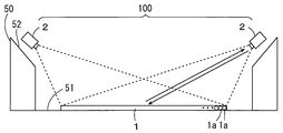
- FIGS. 1 and 2 are a schematic side view and a schematic plan view for describing the configuration of an image display device according to a first embodiment.
- the image display device 100 according to the present embodiment is provided in a stadium 50 such as a baseball stadium or a soccer stadium.
- the stadium 50 of FIGS. 1 and 2 has a circular field 51.
- An annular audience seat 52 is provided outside the field 51 and obliquely above the field 51 so as to surround the field 51. A plurality of observers are accommodated in the spectator seat 52.
- the image display device 100 includes a reflection unit 1 and a plurality of projectors 2.
- the reflecting portion 1 is made of a retroreflecting material and is provided so as to cover the field 51.
- the plurality of projectors 2 are provided on the spectator seat 52 so as to surround the field 51.
- a plurality of observation areas 52 a are set in the audience seat 52 so as to be arranged in the circumferential direction of the field 51.
- the plurality of projectors 2 are provided so as to correspond to the plurality of observation regions 52a, respectively.
- 18 observation regions 52a having a constant angle AR (for example, 20 degrees) with respect to the center CP of the field 51 are set.
- a corresponding projector 2 is provided at the center of each observation region 52a.
- 18 projectors 2 are provided at an angle AR with respect to the center CP of the field 51.
- Each projector 2 emits a light beam group composed of a plurality of light beams toward the reflection unit 1.
- Each ray group represents an image, and each ray corresponds to a pixel of the image.
- the reflection unit 1 includes a plurality of retroreflective elements 1a, and reflects and diffuses the light beam emitted from each projector 2 toward the corresponding observation region 52a. Details of the retroreflective element 1a will be described later.
- Each projector 2 includes, for example, a light source, a spatial light modulator, and a projection system including a plurality of lenses and optical elements.
- a spatial light modulator for example, DMD (Digital Micromirror Device), LCD (Liquid Crystal Display), or LCOS (Liquid Crystal on Silicon) is used.
- a laser projector including a laser light source and a MEMS (Micro Electro Mechanical Systems) mirror may be used.
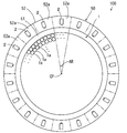
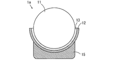
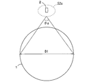
- FIG. 3 is a schematic cross-sectional view showing a specific configuration of the retroreflective element 1a.
- the retroreflective element 1a of FIG. 3 has a spherical shape.
- the retroreflective element 1 a includes a spherical lens 11 and a reflective layer 12.
- the reflective layer 12 is provided so as to cover the lower region of the outer surface of the spherical lens 11.
- the reflective layer 12 has a hemispherical reflective surface 12 a that faces the outer surface of the spherical lens 11.
- a diffusion layer 13 is disposed between the reflection surface 12 a of the reflection layer 12 and the outer surface of the spherical lens 11.
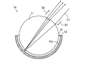
- the spherical lens 11 has a function of collecting incident parallel light on a spherical surface inside the sphere.
- the diffusing layer 13 may be formed of a periodic lens-like or non-periodic uneven structure provided on the surface of the spherical lens 11 or the reflecting surface 12a of the reflecting layer 12, and is holographic.
- the sheet may be configured by being attached to the surface of the spherical lens 11 or the reflecting surface 12a of the reflecting layer 12.
- the diffusion layer 13 may be constituted by a resin layer containing a minute light diffusion material.
- the minute light diffusing material may have, for example, an elliptical shape or a fiber shape.
- each projector 2 in FIG. 1 is arranged obliquely above the retroreflective element 1a, the light beam L1 emitted from each projector 2 comes from obliquely above the retroreflective element 1a, and the spherical lens 11 Is incident on the spherical lens 11 from the exposed surface.
- the light beam L1 incident on the spherical lens 11 is reflected by the reflecting surface 12a of the reflecting layer 12, is diffused by the diffusing layer 13 in a certain angle range, and is emitted from the spherical lens 11.
- the direction D2 of the light beam L1 emitted from the spherical lens 11 is parallel to the direction of the light beam L1 incident on the spherical lens 11. Therefore, the light beam L1 emitted from the spherical lens 11 returns to the projector 2 or the vicinity thereof.
- the light beam L1 is diffused by the diffusion layer 13, so that the light beam L1 emitted from the spherical lens 11 returns to an area within a certain range centered on the projector 2.
- the diffusion performance of the diffusion layer 13 is adjusted so that the light beam L1 returns to the entire observation region 52a.
- the diffusion layer 13 is configured such that the light beam L1 is diffused in the first angle range in the vertical direction and is diffused in the second angle range that is larger than the first angle range in the horizontal direction. Thereby, even when the horizontal angle range of the observation region 52a is larger than the vertical angle range, the light beam L1 reflected and diffused by the retroreflective element 1a returns to the entire observation region 52a.
- the plurality of retroreflective elements 1a may be individually arranged or integrated as a module.
- the plurality of retroreflective elements 1 a are individually arranged, for example, the plurality of retroreflective elements 1 a are spread by being scattered on the field 51. Thereby, the plurality of retroreflective elements 1 a can be easily arranged on the field 51.
- the several retroreflective element 1a can be sucked in using a vacuum cleaner etc., for example.
- the reflection unit 1 is divided into a plurality of regions, and each region is configured by a module including a plurality of retroreflective elements 1a.
- Each module may be formed by integrating a plurality of retroreflective elements 1a on a sheet that can be wound in a roll, or a plurality of retroreflective elements 1a are integrated on a panel. May be formed.
- a plurality of retroreflective elements 1 a can be easily arranged on the field 51 by laying a plurality of modules on the field 51.
- the reflection part 1 made of a retroreflecting material prevents an image from being distorted and displayed even when a non-planar image display surface is used.
- a plurality of retroreflective elements 1a are laid on a non-flat lawn or the water surface of a pool. In this case, since the image is prevented from being distorted and displayed, the observer can observe the image without feeling uncomfortable.
- the reflection unit 1 preferably reflects and diffuses each light beam group so that light beams from a plurality of projectors 2 corresponding to different observation regions 52a do not go to the same observation region 52a. In this case, it is possible to prevent a plurality of images corresponding to different observation areas 52a from being observed in the same observation area 52a.
- the adjacent observation regions 52a may be separated so that the light beams from the plurality of projectors 2 corresponding to the different observation regions 52a do not go to the same observation region 52a.
- a passage may be provided between adjacent observation areas 52a, or use of a spectator seat between adjacent observation areas 52a may be prohibited.
- the plurality of projectors 2 emit light beams representing different images. Thereby, different images are observed in different observation regions 52a.
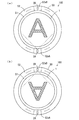
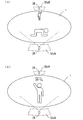
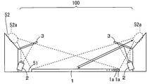
- FIG. 4 is a schematic plan view for explaining images observed from different observation regions 52a.
- FIG. 5 is a schematic perspective view for explaining images observed from different observation regions 52a.
- 4 (a) and 5 (a) show images displayed by one projector
- FIG. 4 (b) and FIG. 5 (b) show images displayed by another projector 2, respectively. Is shown respectively.
- one projector 2 in FIGS. 4A and 5A is referred to as a projector 2A
- the other projector 2 in FIGS. 4B and 5B is referred to as a projector 2B.
- the observation area 52a corresponding to the projector 2A is referred to as an observation area 52aA
- the observation area 52a corresponding to the projector 2B is referred to as an observation area 52aB.
- the projectors 2A and 2B are arranged so as to face each other with the reflector 1 interposed therebetween.
- the image displayed by the projector 2A and the image displayed by the projector 2B are opposite to each other in plan view. Therefore, the direction of the image observed in the observation area 52aA is the same as the direction observed in the observation area 52aB.
- the image displayed by the projector 2 ⁇ / b> A and the image displayed by the projector 2 ⁇ / b> B respectively represent common three-dimensional content that is virtually presented on the reflector 1 (on the field 51).
- an image corresponding to the case where the three-dimensional content is observed from the observation area 52aA is displayed by the projector 2A.
- an image corresponding to the case where the three-dimensional content is observed from the observation area 52aB is displayed by the projector 2B.
- each observation region 52a common three-dimensional content can be observed from the direction according to the observation region 52a. Therefore, for example, in a soccer stadium, a soccer game may be virtually presented on the reflection unit 1 as three-dimensional content. In this case, actual soccer matches are photographed at a plurality of positions corresponding to the plurality of observation areas 52a. The plurality of acquired images are displayed on the reflection unit 1 by the plurality of projectors 2, respectively. Thereby, in each observation area
- a plurality of images are displayed on the reflection unit 1 by the plurality of projectors 2 so that a three-dimensional CG content created using a computer graphics (CG) technique is virtually presented on the reflection unit 1.
- CG computer graphics
- a plurality of images respectively corresponding to the case where the CG content is observed from the plurality of observation regions 52a are created.
- the plurality of created images are displayed on the reflection unit 1 by the plurality of projectors 2, respectively. Thereby, in each observation region 52a, the three-dimensional CG content can be observed from a direction corresponding to the observation region 52a.
- an additional image such as character information may be superimposed on one or a plurality of selected images among the plurality of images displayed by the plurality of projectors 2.
- different additional images may be superimposed on a plurality of images. For example, when Japanese observers are gathered in one observation area 52a and French observers are gathered in the other observation area 52b, an image observed from one observation area 52a is Japanese. Word character information may be superimposed, and French character information may be superimposed on an image observed from another observation area 52a.
- acoustic devices that emit different sounds to the plurality of observation areas 52a may be provided. For example, recording is performed at a plurality of positions corresponding to a plurality of observation areas 52a in a venue where a soccer game is actually played. The sound is emitted to each of the plurality of observation areas 52a. Thereby, cheers etc. in the actual venue can be heard in each observation area 52a. Thereby, a higher sense of reality can be obtained.
- public viewing is performed at a plurality of venues, it is also possible to share sound between the plurality of venues. Thereby, it is possible to form a sense of unity among a plurality of venues.
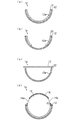
- FIGS. 6 and 7 are schematic cross-sectional views showing other examples of the retroreflective element 1a. Differences of the retroreflective element 1a shown in FIGS. 6 and 7 from the example shown in FIG. 3 will be described.
- the reflection surface 12a of the reflection layer 12 is formed so that the direction of the light beam that arrives at the reflection surface 12a matches the direction in which the light beam reflected by the reflection surface 12a travels.
- the reflecting surface 12a is, for example, a parabolic curved surface, a conical surface, a polygonal pyramid surface, or a polyhedral surface (a plurality of surfaces constituting the polyhedron).
- the light beam group emitted from each projector 2 is reflected and diffused by the plurality of retroreflective elements 1a, and returns to the corresponding observation region 52a.
- the manufacturing can be simplified as compared with the example of FIG.
- FIG. 6B has the same configuration as the example of FIG. 6A except that the diffusion layer 13 is not provided on the bottom of the reflective surface 12a of the reflective layer 12.
- the retroreflective element 1a of FIG. As described above, the light beam emitted from each projector 2 arrives obliquely from the upper side with respect to the retroreflective element 1a, so that the possibility that the light beam reaches the bottom of the reflecting surface 12a is low. Therefore, even if the diffusion layer 13 is not provided on the bottom of the reflective surface 12a, the same function as the example of FIG. 6A is realized. Further, in this example, it is possible to simplify the manufacturing as in the example of FIG. 6A, and it is possible to prevent stray light from being diffusely reflected from the bottom of the reflecting surface 12a. Therefore, the image quality is improved.
- the direction of light rays that arrive at each retroreflective element 1a differs depending on the positional relationship between each retroreflective element 1a and each projector 2, the angle of view of each projector 2, and the like. Therefore, the arrival position of the light beam on the reflecting surface 12a is calculated in advance based on the positional relationship between each retroreflective element 1a and each projector 2, the angle of view of each projector 2, and the like. The region on the reflective surface 12a where the layer 13 is formed may be adjusted.
- the diffusion layer 13 is not provided on the reflection surface 12a of the reflection layer 12, but a plate-like or sheet-like shape so as to cover the space surrounded by the reflection surface 12a.
- a diffusion layer 13 is provided.
- the light beam emitted from each projector 2 is reflected by the reflection surface 12a and diffused by the diffusion layer 13, and returns to the corresponding observation region 52a.
- light rays are easily diffused over a wide range. Therefore, it is necessary to accurately adjust the diffusion performance of the diffusion layer 13 and the shape of the reflection surface 12a so that the light beam returns to the corresponding observation region 52a.
- the manufacturing can be further simplified.
- the light shielding film 14 is formed so as to cover the outer surface of the spherical lens 11 except for the annular opening region 14a.
- the light beam emitted from each projector 2 enters the spherical lens 11 through the opening region 14a.
- the light reflected and diffused by the reflecting surface 12a and the diffusion layer 13 is emitted toward the corresponding observation region 52a through the opening region 14a.
- external light such as sunlight and stray light are shielded by the light shielding film 14. Thereby, the image displayed by each projector 2 becomes clearer.
- the direction of light rays arriving at each retroreflective element 1a depends on the positional relationship between each retroreflective element 1a and each projector 2, the angle of view of each projector 2, and the like. Different. Therefore, based on the positional relationship between each retroreflective element 1a and each projector 2, the angle of view of each projector 2, and the like, the incident position of the light beam to the spherical lens 11 and the emission position of the light beam from the spherical lens 11 are calculated. The position and size of the opening region 14a may be adjusted based on the calculation result. In this case, the light beam emitted from each projector 2 and the light beam to be returned to each observation region 52a are prevented from being blocked by the light shielding film 14.
- FIG. 7 shows an example of a method for forcibly adjusting the posture of the retroreflective element 1a of FIG.
- a weight 15 is provided on the lower surface of the reflective layer 12.
- the posture of each retroreflective element 1a is naturally adjusted by the weight 15 so that the exposed surface of the spherical lens 11 faces upward.
- a water layer is formed on the field 51 of FIG. 1, and a plurality of retroreflective elements 1a are arranged so as to float on the water layer. In this case, the exposed surface of the spherical lens 11 is directed upward by sinking the weight 15 downward.
- the image display apparatus 100 may function in that state, or each retroreflective element 1a is arranged on the field 51 so that the exposed surface of the spherical lens 11 faces upward by removing water on the field 51. In this state, the image display device 100 may function.
- a magnet may be used instead of a weight.
- the posture of each retroreflective element 1a can be adjusted more easily and accurately. Even when the retroreflective elements 1a are arranged on a non-horizontal surface, the posture of each retroreflective element 1a can be easily adjusted.
- FIGS. 3, 6, and 7 may be combined.
- a part of the diffusion layer 13 may not be provided as in the example of FIG. 6 (b).
- the diffusion layer 13 of FIG. 6 (c) may be provided.
- the weight 15 of FIG. 7 may be provided in the retroreflective element 1a of FIGS. 6 (a) to 6 (d).
- a corner reflector may be used as the retroreflective element 1a.
- a plurality of configurations shown in FIGS. 3, 6 and 7 may be combined with the corner reflector.
- the diffusion layer 13 of FIG. 3 may be provided on the reflection surface of the corner reflector, or the light shielding film 14 of FIG. 6D may be provided so as to cover a part of the reflection surface of the corner reflector.
- Pixel Pitch and Number of Pixels As described above, the light beam emitted from each projector 2 corresponds to a pixel of an image displayed on the reflection unit 1.
- the distance between the centers of two adjacent pixels is referred to as a pixel pitch.
- the pixel pitch is set so that the observer can observe the image without feeling uncomfortable.
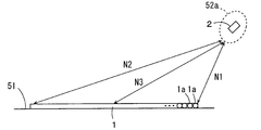
- 8 and 9 are a schematic side view and a schematic plan view for explaining the pixel pitch and the number of pixels of the image displayed by the projector 2. 8 and 9, only one observation region 52a is shown.
- the shortest distance between the observation region 52a and the reflecting portion 1 is N1.
- the distance N1 is, for example, the distance between the observer in the front row of the observation region 52a and the retroreflective element 1a closest to the observer.
- the resolution of the viewing angle of an observer with standard visual acuity is assumed to be ⁇ (radian).
- the resolution ⁇ may be set to a constant value in advance. For example, when the visual acuity of the observer is 1.0, the visual angle resolution ⁇ is about 0.000291 radians (1/60 degrees).
- D1 is a lower limit dimension that can be visually recognized at a position separated by a distance N1 by an observer having standard visual acuity (for example, visual acuity 1.0). Therefore, by setting the pixel pitch to be smaller than the dimension d1, almost all observers in each observation region 52a can observe the image displayed on the reflection unit 1 without a sense of incongruity.
- standard visual acuity for example, visual acuity 1.0
- the dimension d1 is about 1.54 cm.
- the pixel pitch is preferably set to be smaller than 1.54 cm.
- the pitch of the retroreflective elements 1a is preferably equal to or less than the pixel pitch.
- the pitch of the retroreflective elements 1a is the distance between the centers of two adjacent retroreflective elements 1a.
- the pitch of the retroreflective elements 1a is substantially equal to the horizontal dimension (diameter) of the retroreflective elements 1a.
- the pitch of the retroreflective elements 1a is preferably smaller than the dimension d1, and more preferably half or less of the dimension d1.
- the longest distance between the observation region 52a and the reflection part 1 is N2.
- the distance N2 is, for example, the distance between the observer in the front row of the observation region 52a and the retroreflective element 1a farthest from the observer. Further, the distance between the observation region 52a and the center of the reflecting portion 1 is N3.
- the dimension d2 is approximately 5.12 cm and the dimension d3 is approximately 2.97 cm. is there.
- the pitch of the retroreflective elements 1 a may be different depending on the position on the reflecting portion 1.
- the pitch of the retroreflective elements 1a it is necessary to consider not only one observation region 52a but all the observation regions 52a.
- the pitch of the retroreflective elements 1a can be maximized at the center of the reflecting portion 1.
- the upper limit value of the pitch of the retroreflective elements 1a at the center of the reflecting portion 1 is the dimension d3 (for example, about 2.97 cm) obtained from the distance N3 in FIG. The closer to the outer periphery of the reflecting portion 1, the smaller the upper limit value of the preferred pitch of the retroreflective element 1a.
- the pixel pitch may be different depending on the position on the reflecting portion 1.
- the image displayed by one projector 2 is observed only from the observation area 52a corresponding to the projector 2. Therefore, only one observation region 52a needs to be considered for the pixel pitch.
- the upper limit value of the pixel pitch on the central portion of the reflecting portion 1 is the dimension d3 (for example, about 2.97 cm) obtained from the distance N3 in FIG. 8, and the position on the reflecting portion 1 farthest from the observation region 52a.
- the upper limit value of the pixel pitch at is a dimension d2 (for example, about 5.12 cm) obtained from the distance N2 in FIG.
- the required number of pixels is obtained based on the pixel pitch set as described above. As shown in FIG. 9, the diameter of the reflection part 1 is set to D1.
- the maximum number of pixels necessary in the horizontal direction is a value obtained by dividing the diameter D1 by the pixel pitch (D1 / pixel pitch). For example, when the pixel pitch is set to be smaller than 1.54 cm as described above and the diameter D1 is 150 m, the maximum number of pixels required in the horizontal direction is more than about 9726 pixels.
- the number of pixels in the horizontal direction can be obtained based on the viewing angle of the observer.
- the viewing angle of the observer in the diameter direction of the reflecting portion 1 is ⁇ a.
- the number of pixels necessary in the diameter direction of the reflecting portion 1 is represented by ⁇ a / ⁇ .
- the number of pixels necessary in the diameter direction is 4380 pixels.
- the approximate number of retroreflective elements 1a required is represented by a value obtained by dividing the area of the reflective portion 1 by the area of each retroreflective element 1a.
- the required number of retroreflective elements 1a is about 100 million.
- each projector 2 displays a part of an image to be observed by an observer (hereinafter referred to as a partial image).
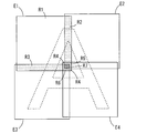
- FIG. 10 is a schematic diagram for explaining connection of partial images.
- four projectors 2 are provided for one observation region 52a.
- the four partial images E1, E2, E3, and E4 respectively displayed by the four projectors 2 are connected, so that one image to be observed from one observation region 52a (hereinafter referred to as a connected image). ) Is configured.
- the partial images E1 to E4 are displayed on the reflecting portion 1 of FIG. 2 so as to partially overlap each other. In this case, an unnatural gap is prevented from being formed between the partial images E1 to E4.
- each region of each partial image is adjusted so that the luminance of the region overlapping with the other partial image is smaller than the luminance of the region not overlapping with the other partial image.
- the region R1 of the partial image E1 does not overlap with any of the other partial images E2, E3, E4.
- the region R2 of the partial image E1 overlaps only the partial image E2
- the region R3 overlaps only the partial image E3
- the region R4 overlaps only the partial image E4.
- the region R5 of the partial image E1 overlaps with the partial images E2 and E4, and the region R6 overlaps with the partial images E3 and E4.
- the region R7 of the partial image E1 overlaps with the partial images E2, E3, E4.
- the brightness of the areas R2, R3, R4 is set smaller than the brightness of the area R1
- the brightness of the areas R5, R6 is set lower than the brightness of the areas R2, R3, R4
- the brightness of the area R7 is It is set smaller than the luminance of R5 and R6.
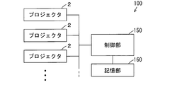
- FIG. 11 is a block diagram for explaining a control system of the image display apparatus 100.
- the image display device 100 includes a control unit 150 and a storage unit 160.
- the control unit 150 includes, for example, a general-purpose computer or an embedded device, and controls the plurality of projectors 2 so that different images are observed in the plurality of observation regions 52a (FIG. 2).
- the storage unit 160 includes, for example, a storage medium such as a magnetic disk, an optical disk, or a fresh memory, or a main memory, and stores a plurality of image data corresponding to a plurality of images to be displayed by the plurality of projectors 2. These image data may be image data acquired in the past at the main stadium 50 or another stadium, or may be image data representing CG content.
- a storage medium such as a magnetic disk, an optical disk, or a fresh memory, or a main memory
- an event for example, a soccer game
- the image data may be transmitted to the control unit 150 in real time by radio waves or communication lines and stored in the storage unit 160.
- the image data transmitted in this way may be displayed by the projector 2 in real time.
- image data corresponding to an additional image such as character information may be stored in the storage unit 160.
- an additional image is created by the control unit 150, for example, and appropriately superimposed on the image displayed by the projector 2.
- control unit 150 may perform various corrections on the image data. For example, in order to prevent image variations due to individual differences of the projectors 2, correction parameters corresponding to the projectors 2 may be stored in the storage unit 160 in advance, and correction may be performed based on the correction parameters. In addition, other corrections such as distortion correction, color correction, or overlap correction may be appropriately performed.
- the light beam emitted from each projector 2 is reflected and diffused toward the corresponding observation region 52 a by the reflection unit 1 provided on the field 51. Is done. Thereby, the image displayed on the field 51 from each observation area
- the plurality of projectors 2 are controlled so that different images are observed in the plurality of observation regions 52a. Thereby, the image according to the observation area
- a plurality of observers can simultaneously observe a common image in each observation region 52a. Therefore, the required number of projectors 2 is smaller than the number of observers, and an increase in cost is suppressed. Further, since it is not necessary for each observer to wear the projector 2, there is no physical burden on each observer.
- the reflecting portion 1 is composed of a plurality of retroreflective elements 1a, a group of light beams emitted from each projector 2 is reflected and diffused by the plurality of retroreflective elements 1a. Return to the observation area 52a. Thereby, with a simple configuration, a plurality of observers can simultaneously observe a common image in each observation region 52a.
- FIG. 12 is a schematic side view for explaining the image display apparatus 100 according to the second embodiment.
- an optical member 3 is disposed between each projector 2 and the reflecting section 1.
- Each optical member 3 is, for example, a half mirror.
- Each projector 2 is provided at a position different from the corresponding observation area 52a. In this example, each projector 2 is provided at a position lower than the audience seat 52 inside the corresponding observation area 52a.
- each projector 2 The light beam emitted from each projector 2 is reflected by each optical member 3 and guided to the reflecting section 1.
- the light beam group reflected by the reflecting unit 1 is guided through the optical members 3 to the observation region 52a.
- each projector 2 is in a conjugate position with respect to a specific position (for example, the center position) in the corresponding observation region 52a.
- the light beam emitted by each projector 2 is reflected and diffused by the reflecting unit 1 and guided to the corresponding observation region 52a. Accordingly, it is possible to observe different images from the plurality of observation regions 52a and to observe a common image by a plurality of observers in each observation region 52a.
- each projector 2 can be changed as appropriate. Therefore, each projector 2 is prevented from obstructing the observation of the image by the observer. Further, the light emitted from each projector 2 is prevented from being blocked by the observer.
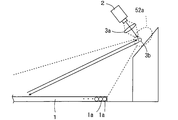
- FIG. 13 is a schematic side view for explaining an example in which a lens and a small total reflection mirror are used.
- FIG. 13 shows one projector 2 and one corresponding lens and one total reflection mirror.
- a total reflection mirror 3b is provided in each observation region 52a.
- the projector 2 is provided at a position higher than the spectator seat 52, and the lens 3a is disposed between the projector 2 and the total reflection mirror 3b.
- the light beam emitted from the projector 2 is collected by the lens 3a and reflected toward the reflecting unit 1 by the total reflection mirror 3b.
- the position of each projector 2 can be changed without using the large optical member 3.
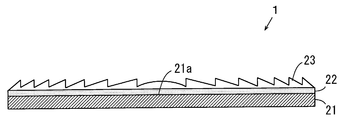
- FIG. 14 is a schematic side view showing the configuration of the reflecting section 1 used in the third embodiment.
- the 14 includes a reflecting plate 21, a diffusion layer 22, and a Fresnel lens 23.
- a reflection surface 21a is provided on the upper surface of the reflection plate 21, and a diffusion layer 22 and a Fresnel lens 23 are sequentially laminated on the reflection surface 21a.
- the diffusion layer 22 has the same configuration as the diffusion layer 13 of FIG.
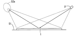
- FIG. 15 is a schematic side view for explaining the operation of the reflecting section 1 of FIG. 14 used in the third embodiment.
- FIG. 15 shows one projector 2 and an observation area 52a corresponding thereto.
- the light beam emitted by each projector 2 is reflected and diffused by the reflecting plate 21 and the diffusion layer 22 of the reflecting portion 1 and is condensed by the Fresnel lens 23 on the corresponding observation region 52a.
- the projector 2 corresponding to each observation region 52a is arranged on the opposite side of each observation region 52a with the reflector 1 interposed therebetween.
- the Fresnel lens 23 can be easily arranged by laying a plurality of sheet-like lens portions or a plurality of panel-like lens portions on the field 51.
- the diffusion layer 22 is provided between the reflecting plate 21 and the Fresnel lens 23, but the diffusion layer 22 may be provided on the Fresnel lens 23.
- the reflecting section 1 is provided on the horizontal field 51, and a plurality of observation regions 52a are set in the spectator seat 52 provided so as to surround the field 51.
- the present invention is not limited to this.
- the reflection unit 1 may be provided on one surface of a vertical screen, and a plurality of observation regions 52a may be set in a region where one surface of the screen can be observed.
- the present invention can be applied in a movie theater or a theater.
- the water surface of the pool can be used as an image display surface.
- a plurality of retroreflective elements 1a can be easily arranged on the water surface of the pool. Thereby, an image displayed on the water surface of the pool can be observed from around the pool.
- the present invention may be applied to a small place, not a large venue such as a stadium.
- the image display device may be configured such that the upper surface of a table such as a pool table is an image display surface, and an image displayed on the table is observed from the periphery.
- three-dimensional content such as a soccer game can be reduced and presented virtually on the table.
- the reflective part is configured by a plurality of retroreflective elements and the size of the reflective part and the distance from the reflective part to each observation region are reduced in a similar shape
- the number of retroreflective elements is the original The configuration is the same, and the size of each retroreflective element is set to be small in proportion to the reduction ratio.
- the light beam reflected by the reflecting portion 1 is diffused by the diffusion layers 13 and 22, but the present invention is not limited to this.
- the diffusion layers 13 and 22 may not be provided.
- each light beam reaches the eyes of a plurality of observers in the observation region 52a due to a slight spread of each light beam itself.
- a plurality of observers can observe images simultaneously in each observation region 52a.
- the image display device 100 is an example of an image display device
- the observation region 52a is an example of an observation region
- the field 51 is an example of an image display surface
- the projector 2 is an example of a light generator.
- the reflection unit 1 is an example of a reflection unit
- the control unit 150 is an example of a control unit
- the diffusion layer 13 is an example of a diffusion unit
- the retroreflection element 1a is an example of a retroreflection element
- the reflective surface 21a is an example of a reflective surface
- the Fresnel lens 23 is an example of a lens.
- the present invention can be effectively used when a plurality of people observe images at the same time, for example, public viewing.
Landscapes
- Physics & Mathematics (AREA)
- General Physics & Mathematics (AREA)
- Engineering & Computer Science (AREA)
- Multimedia (AREA)
- Signal Processing (AREA)
- Optics & Photonics (AREA)
- Projection Apparatus (AREA)
- Overhead Projectors And Projection Screens (AREA)
- Transforming Electric Information Into Light Information (AREA)
Priority Applications (1)
| Application Number | Priority Date | Filing Date | Title |
|---|---|---|---|
| US15/326,898 US9927628B2 (en) | 2014-07-18 | 2015-06-15 | Image display apparatus |
Applications Claiming Priority (2)
| Application Number | Priority Date | Filing Date | Title |
|---|---|---|---|
| JP2014147858A JP5999662B2 (ja) | 2014-07-18 | 2014-07-18 | 画像表示装置 |
| JP2014-147858 | 2014-07-18 |
Publications (1)
| Publication Number | Publication Date |
|---|---|
| WO2016009588A1 true WO2016009588A1 (ja) | 2016-01-21 |
Family
ID=55078103
Family Applications (1)
| Application Number | Title | Priority Date | Filing Date |
|---|---|---|---|
| PCT/JP2015/002988 WO2016009588A1 (ja) | 2014-07-18 | 2015-06-15 | 画像表示装置 |
Country Status (3)
| Country | Link |
|---|---|
| US (1) | US9927628B2 (ko) |
| JP (1) | JP5999662B2 (ko) |
| WO (1) | WO2016009588A1 (ko) |
Families Citing this family (8)
| Publication number | Priority date | Publication date | Assignee | Title |
|---|---|---|---|---|
| JP6852329B2 (ja) * | 2016-09-21 | 2021-03-31 | セイコーエプソン株式会社 | 立体画像表示装置 |
| US10584504B2 (en) * | 2017-11-08 | 2020-03-10 | Nicole Drakulich | Modular projection systems, enclosures and wellness studios |
| JP7044237B2 (ja) * | 2017-11-14 | 2022-03-30 | ピクシーダストテクノロジーズ株式会社 | 空中スクリーン形成装置、画像投影システム |
| US10877070B2 (en) * | 2018-01-19 | 2020-12-29 | Formfactor Beaverton, Inc. | Probes with fiducial targets, probe systems including the same, and associated methods |
| JP7078205B2 (ja) * | 2018-04-24 | 2022-05-31 | 日本電信電話株式会社 | 表示システム |
| US10618340B2 (en) | 2018-05-16 | 2020-04-14 | Viavi Solutions Inc. | Security feature based on a single axis alignment of mirrors in a structured surface that forms a micro mirror array |
| JP7383261B2 (ja) * | 2020-05-13 | 2023-11-20 | 日本電信電話株式会社 | 立体映像投影装置とその表示方法 |
| JPWO2022209986A1 (ko) * | 2021-03-30 | 2022-10-06 |
Citations (4)
| Publication number | Priority date | Publication date | Assignee | Title |
|---|---|---|---|---|
| JP2000275755A (ja) * | 1999-03-24 | 2000-10-06 | Hitachi Ltd | 画像表示装置および指向性反射スクリーン |
| WO2006027855A1 (ja) * | 2004-09-10 | 2006-03-16 | Hitachi, Ltd. | 表示装置及び撮像装置 |
| JP2010002894A (ja) * | 2008-05-23 | 2010-01-07 | Nanao Corp | 立体画像表示システム |
| JP2013210592A (ja) * | 2012-03-30 | 2013-10-10 | National Institute Of Information & Communication Technology | 立体ディスプレイ |
Family Cites Families (9)
| Publication number | Priority date | Publication date | Assignee | Title |
|---|---|---|---|---|
| US6665100B1 (en) * | 1999-08-10 | 2003-12-16 | Zebra Imaging, Inc. | Autostereoscopic three dimensional display using holographic projection |
| JP2005055822A (ja) | 2003-08-07 | 2005-03-03 | Seiko Epson Corp | 投影表示システム |
| JP4625945B2 (ja) | 2004-06-28 | 2011-02-02 | 国立大学法人 東京大学 | 画像表示装置 |
| JP2008249897A (ja) | 2007-03-29 | 2008-10-16 | Toshiba Corp | 観察可能人数の切替え機能付スクリーン及び投射型画像表示装置のシステム |
| WO2009011946A1 (en) | 2007-04-17 | 2009-01-22 | University Of Southern California | Rendering for an interactive 360 degree light field display |
| US9465283B2 (en) * | 2009-11-06 | 2016-10-11 | Applied Minds, Llc | System for providing an enhanced immersive display environment |
| US20130286481A1 (en) * | 2011-01-19 | 2013-10-31 | Nippon Carbide Industries Co., Inc. | Micro glass bead retroreflective sheeting having image with directional visibility thereon |
| JP2014511509A (ja) * | 2011-02-28 | 2014-05-15 | ヒューレット−パッカード デベロップメント カンパニー エル.ピー. | 前面投影グラスレス(glasses−free)連続3Dディスプレイ |
| WO2013188690A2 (en) * | 2012-06-15 | 2013-12-19 | Michael Wang | Projector based display systems and methods |
-
2014
- 2014-07-18 JP JP2014147858A patent/JP5999662B2/ja not_active Expired - Fee Related
-
2015
- 2015-06-15 WO PCT/JP2015/002988 patent/WO2016009588A1/ja active Application Filing
- 2015-06-15 US US15/326,898 patent/US9927628B2/en not_active Expired - Fee Related
Patent Citations (4)
| Publication number | Priority date | Publication date | Assignee | Title |
|---|---|---|---|---|
| JP2000275755A (ja) * | 1999-03-24 | 2000-10-06 | Hitachi Ltd | 画像表示装置および指向性反射スクリーン |
| WO2006027855A1 (ja) * | 2004-09-10 | 2006-03-16 | Hitachi, Ltd. | 表示装置及び撮像装置 |
| JP2010002894A (ja) * | 2008-05-23 | 2010-01-07 | Nanao Corp | 立体画像表示システム |
| JP2013210592A (ja) * | 2012-03-30 | 2013-10-10 | National Institute Of Information & Communication Technology | 立体ディスプレイ |
Also Published As
| Publication number | Publication date |
|---|---|
| US20170205634A1 (en) | 2017-07-20 |
| JP5999662B2 (ja) | 2016-09-28 |
| US9927628B2 (en) | 2018-03-27 |
| JP2016024311A (ja) | 2016-02-08 |
Similar Documents
| Publication | Publication Date | Title |
|---|---|---|
| JP5999662B2 (ja) | 画像表示装置 | |
| EP2685313B1 (en) | Multi-projection system | |
| TW571120B (en) | Three-dimensional display method and its device | |
| US9053660B2 (en) | Combined-screen-based multi-pitching angle suspended panoramic space 3D display device | |
| US11536959B2 (en) | Image display apparatus | |
| JP3955589B2 (ja) | 立体表示装置 | |
| CN107820578A (zh) | 用于在可穿戴式平视显示器中进行适眼区扩大的系统、设备和方法 | |
| JP2016500829A (ja) | 収束角度スライス型の真の3dディスプレイ | |
| US10887566B2 (en) | Image display system | |
| WO2019017812A1 (ru) | Стереодисплей (варианты) | |
| JPWO2010095486A1 (ja) | 立体表示装置 | |
| JP5888742B2 (ja) | 立体表示装置 | |
| WO2013069589A1 (ja) | 反射型スクリーン及びそれを備えた投射型表示装置 | |
| JP2006276292A (ja) | 映像表示システム | |
| US20040179263A1 (en) | Stereoscopic image display apparatus | |
| US10110885B2 (en) | Three-dimensional image display apparatus | |
| JP2006085135A (ja) | 立体表示装置 | |
| WO2022209986A1 (ja) | 表示装置 | |
| JP2007140500A (ja) | 無限遠視表示装置及び無限遠視プラネタリウム装置 | |
| US20070242227A1 (en) | Method for aerial display of images | |
| US20240061249A1 (en) | Single pupil rgb light source | |
| KR20080112832A (ko) | 입체영상 표시시스템 | |
| JP6890006B2 (ja) | 光学スクリーン、多視点映像表示装置および立体像表示装置 | |
| JPH0743664A (ja) | 投写型画像表示装置 | |
| JP2006113476A (ja) | 映像表示システム |
Legal Events
| Date | Code | Title | Description |
|---|---|---|---|
| 121 | Ep: the epo has been informed by wipo that ep was designated in this application |
Ref document number: 15822314 Country of ref document: EP Kind code of ref document: A1 |
|
| WWE | Wipo information: entry into national phase |
Ref document number: 15326898 Country of ref document: US |
|
| NENP | Non-entry into the national phase |
Ref country code: DE |
|
| 122 | Ep: pct application non-entry in european phase |
Ref document number: 15822314 Country of ref document: EP Kind code of ref document: A1 |