WO2016006635A1 - ガスセンサ素子 - Google Patents
ガスセンサ素子 Download PDFInfo
- Publication number
- WO2016006635A1 WO2016006635A1 PCT/JP2015/069694 JP2015069694W WO2016006635A1 WO 2016006635 A1 WO2016006635 A1 WO 2016006635A1 JP 2015069694 W JP2015069694 W JP 2015069694W WO 2016006635 A1 WO2016006635 A1 WO 2016006635A1
- Authority
- WO
- WIPO (PCT)
- Prior art keywords
- gas
- cell
- sensor
- measured
- gas inlet
- Prior art date
- Legal status (The legal status is an assumption and is not a legal conclusion. Google has not performed a legal analysis and makes no representation as to the accuracy of the status listed.)
- Ceased
Links
Images


Classifications
-
- G—PHYSICS
- G01—MEASURING; TESTING
- G01N—INVESTIGATING OR ANALYSING MATERIALS BY DETERMINING THEIR CHEMICAL OR PHYSICAL PROPERTIES
- G01N27/00—Investigating or analysing materials by the use of electric, electrochemical, or magnetic means
- G01N27/26—Investigating or analysing materials by the use of electric, electrochemical, or magnetic means by investigating electrochemical variables; by using electrolysis or electrophoresis
- G01N27/403—Cells and electrode assemblies
- G01N27/406—Cells and probes with solid electrolytes
- G01N27/407—Cells and probes with solid electrolytes for investigating or analysing gases
- G01N27/41—Oxygen pumping cells
-
- G—PHYSICS
- G01—MEASURING; TESTING
- G01N—INVESTIGATING OR ANALYSING MATERIALS BY DETERMINING THEIR CHEMICAL OR PHYSICAL PROPERTIES
- G01N27/00—Investigating or analysing materials by the use of electric, electrochemical, or magnetic means
- G01N27/26—Investigating or analysing materials by the use of electric, electrochemical, or magnetic means by investigating electrochemical variables; by using electrolysis or electrophoresis
- G01N27/403—Cells and electrode assemblies
- G01N27/406—Cells and probes with solid electrolytes
- G01N27/407—Cells and probes with solid electrolytes for investigating or analysing gases
- G01N27/4071—Cells and probes with solid electrolytes for investigating or analysing gases using sensor elements of laminated structure
-
- G—PHYSICS
- G01—MEASURING; TESTING
- G01N—INVESTIGATING OR ANALYSING MATERIALS BY DETERMINING THEIR CHEMICAL OR PHYSICAL PROPERTIES
- G01N27/00—Investigating or analysing materials by the use of electric, electrochemical, or magnetic means
- G01N27/26—Investigating or analysing materials by the use of electric, electrochemical, or magnetic means by investigating electrochemical variables; by using electrolysis or electrophoresis
- G01N27/403—Cells and electrode assemblies
- G01N27/406—Cells and probes with solid electrolytes
- G01N27/407—Cells and probes with solid electrolytes for investigating or analysing gases
- G01N27/4073—Composition or fabrication of the solid electrolyte
- G01N27/4074—Composition or fabrication of the solid electrolyte for detection of gases other than oxygen
Definitions
- the present invention relates to a gas sensor element for detecting the concentration of a predetermined gas component contained in a gas to be measured.
- Some gas sensor elements for detecting the concentration of a predetermined gas component in the measurement gas include a pump cell that adjusts the oxygen concentration in the taken measurement gas. By adjusting the oxygen concentration in the gas to be measured by this pump cell, the detection accuracy in the sensor cell of the gas sensor element is prevented from deteriorating due to oxygen in the gas to be measured.
- Japanese Patent Application Laid-Open No. 8-271476 discloses a first internal space in which oxygen is discharged from a gas to be measured by a pump cell, and a second internal space in which the concentration of a predetermined gas component in the gas to be measured is detected by a sensor cell.
- a gas sensor element having a void is disclosed. The gas sensor element is provided between the first diffusion-controlled passage for diffusion-controlling the gas to be measured introduced into the first internal space, and the first internal space and the second internal space. And a second diffusion-controlled passage.
- the gas to be measured introduced from the outside passes through the first and second diffusion-controlled passages until reaching the second internal space where the sensor cell is provided, and the diffusion distance thereof. Will be longer. As a result, it becomes difficult to improve the responsiveness of the gas sensor element.
- the detection accuracy is deteriorated. That is, if the diffusion resistance of the first diffusion rate-limiting passage is reduced, a large amount of gas to be measured is introduced into the first internal space, making it difficult to sufficiently adjust the oxygen concentration in the gas to be measured. . Furthermore, if the diffusion resistance of the second diffusion-controlling passage is small, the gas to be measured is introduced into the second internal space without sufficiently adjusting the oxygen concentration in the first internal space, and the detection accuracy is improved. It will get worse.
- the present invention has been made in view of such a background, and intends to provide a gas sensor element capable of achieving both responsiveness and detection accuracy.
- a predetermined gas in a gas to be measured includes a first portion of a solid electrolyte body having oxygen ion conductivity and a pair of sensor electrodes provided on the solid electrolyte body.
- a sensor cell for detecting the concentration of the component includes a pump cell comprising a second portion of the solid electrolyte body and a pair of pump electrodes provided on the solid electrolyte body, and adjusting the oxygen concentration in the gas to be measured;
- a gas inlet configured to introduce the gas to be measured into the internal space and to give a predetermined diffusion resistance to the gas to be measured introduced into the internal space;
- the dimension of the gas inlet in the flow direction of the gas to be measured in the gas inlet is L1, the cross-sectional area of the gas inlet perpendicular to the flow direction of the gas to be measured in the gas inlet is S1, the gas inlet and the gas Gas sensor satisfying
- the gas sensor element can achieve both responsiveness and detection accuracy by satisfying 1000 ⁇ (L1 / S1) ⁇ (L2 / S2) ⁇ 5000.
- the inventors of the present application have focused on the fact that the responsiveness and detection accuracy greatly depend not only on the configuration of the gas inlet but also on the configuration of the internal space.
- (L1 / S1) is referred to as a first diffusion resistance index for convenience.
- the larger the first diffusion resistance index the slower the introduction rate of the gas to be measured into the internal space.
- the responsiveness is likely to decrease, but the detection accuracy is likely to be improved because the amount of oxygen to be adjusted by the pump cell tends to decrease.
- (L2 / S2) the diffusion resistance until the gas to be measured introduced into the internal space reaches the sensor electrode increases as this increases. Therefore, in this specification, (L2 / S2) is referred to as a second diffusion resistance index for convenience.
- the principle of influence on the responsiveness and the detection accuracy is slightly different between the first diffusion resistance index and the second diffusion resistance index, but as each index is larger, the responsiveness is more likely to decrease and the detection accuracy becomes higher.
- the inventors examined the relationship between the product of the first diffusion resistance index and the second diffusion resistance index, responsiveness, and detection accuracy (Experimental Examples 1 and 2 to be described later).
- the product of the first diffusion resistance index and the second diffusion resistance index that is, (L1 / S1) ⁇ (L2 / S2) is set to 1000 to 5000, thereby achieving both responsiveness and detection accuracy. I found out that it can be achieved.
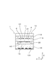
- FIG. 2 is a cross-sectional view taken along line II-II in FIG. 1.
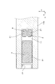
- FIG. 3 is a cross-sectional view taken along line III-III in FIG. 1.
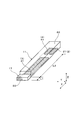
- FIG. 3 is a perspective explanatory view of an internal space and a gas inlet in the first embodiment.
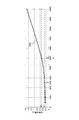
- the diagram which shows the relationship between the product P and the offset current in Experimental Example 1.
- the diagram which shows the relationship between the product P and the response time in Experimental example 2.
- the gas inlet may be composed of a porous body.
- the cross-sectional area S1 can be a value obtained by multiplying the cross-sectional area of the gas inlet by the porosity of the porous body.
- the diffusion resistance in the gas inlet can be easily adjusted, and the response and detection accuracy can be accurately managed by adjusting (L1 / S1) ⁇ (L2 / S2).
- the internal space preferably has a uniform shape from the region facing the pump electrode to the region facing the sensor electrode. In this case, since the gas to be measured introduced into the internal space can smoothly reach the sensor electrode, a gas sensor element with excellent responsiveness can be obtained.
- the cross sectional area S2 is defined as the cross sectional area S2.
- the gas inlet dimension L1 refers to the dimension of the gas inlet in the flow direction of the gas to be measured passing through the gas inlet.
- the cross-sectional area of the gas inlet perpendicular to the flow direction of the gas to be measured passing through the gas inlet differs depending on the flow direction of the gas to be measured
- the cross-sectional area of the portion having the smallest cross-sectional area is set as the cross-sectional area S1.
- the gas sensor element 1 of this example includes a solid electrolyte body 5 having oxygen ion conductivity, a sensor cell 2 for detecting the concentration of a specific gas in the gas to be measured, and a gas in the gas to be measured.
- a predetermined diffusion resistance is given to the pump cell 3 for adjusting the oxygen concentration, the internal space 11 into which the gas to be measured is introduced, and the gas to be measured that flows into the gas sensor element 1 (that is, the internal space 11) from the outside.
- the sensor cell 2 includes a part of the solid electrolyte body 5 having oxygen ion conductivity and a pair of sensor electrodes 21 and 22 provided on the solid electrolyte body 5.
- the pump cell 3 includes another part of the solid electrolyte body 5 and a pair of pump electrodes 31 and 32 provided on the solid electrolyte body 5, and is configured to adjust the oxygen concentration in the gas to be measured.
- the internal space 11 faces one sensor electrode 21 and one pump electrode 31 and is configured to introduce a gas to be measured.
- the gas inlet 17 is configured such that the gas to be measured passes and is introduced into the internal space 11, and functions as a diffusion resistor that imparts a predetermined diffusion resistance to the gas to be measured. .
- the dimension of the gas inlet 17 in the flow direction of the gas to be measured in the gas inlet 17 (in other words, the moving distance of the gas to be measured in the gas inlet 17) is L 1.
- the cross-sectional area of the gas inlet 17 perpendicular to the flow direction of the gas to be measured is S1
- the distance along the flow direction of the gas to be measured between the gas inlet 17 and the sensor cell 2 is L2
- the pump cell 3 and the sensor cell 2 Let S2 be the cross-sectional area of the internal space 11 orthogonal to the arrangement direction.
- L1, S1, L2, and S2 satisfy 1000 ⁇ (L1 / S1) ⁇ (L2 / S2) ⁇ 5000.
- the gas sensor element 1 of this example is a NOx sensor that detects a nitrogen oxide (NOx) concentration. That is, in this example, the gas to be measured is exhaust gas of an internal combustion engine such as an automobile, and the predetermined gas component is NOx.
- NOx nitrogen oxide
- the gas sensor element 1 includes a solid electrolyte body 5, a spacer 110 for forming the internal space 11, an insulating plate 12 facing the solid electrolyte body 5 through the internal space 11, A heater substrate 13 with a built-in heater 131 is laminated.
- the solid electrolyte body 5 is made of zirconia (ZrO 2 ), and the spacer 110, the insulating plate 12, and the heater substrate 13 are all made of alumina (Al 2 O 3 ).
- a reference gas chamber 14 into which air as a reference gas is introduced is formed between the heater substrate 13 and the solid electrolyte body 5, a reference gas chamber 14 into which air as a reference gas is introduced is formed. Further, as shown in FIGS. 1 and 3, a notch (recess) is provided in a part of the tip of the spacer 110, and the notch functions as a gas inlet 17. That is, the gas inlet 17 is formed at the tip of the gas sensor element 1.
- a porous body of alumina is arranged in the gas inlet 17 to give a predetermined diffusion resistance to the gas to be measured. That is, the gas inlet 17 is composed of a porous body of alumina. Therefore, the above-described cross-sectional area S1 is a value obtained by multiplying the cross-sectional area S0 (FIG. 4) of the gas inlet 17 (that is, the porous body) by the porosity of the porous body.
- the cross-sectional area S0 is a cross-sectional area of the porous body orthogonal to the flow direction of the gas to be measured flowing in the gas inlet 17.
- the porosity of the porous body can be measured, for example, by cutting the porous body to form a planar cross section and observing this with a SEM (Scanning Electron Microscope electron microscope) or the like. More specifically, the pores of the porous body are impregnated with a low-viscosity resin, and then cut with a slicer to expose a flat observation cross section. Next, after smoothing the observation cross section, the observation cross section is observed with an SEM. At this time, the area ratio of the aggregate appearing in the cross section is calculated by image processing, and a value obtained by subtracting this area ratio from 100% is calculated as the porosity.
- the gas inlet 17 is formed by a space (hole), and the size and shape of the space are given a predetermined diffusion resistance to the gas to be measured flowing into the internal space 11. You may form in.
- the internal space 11 has a uniform shape from the region where the pump electrode 31 faces to the region where the sensor electrode 21 faces.
- the internal space 11 has a rectangular parallelepiped shape, and has a rectangular shape having substantially the same cross-sectional shape perpendicular to the axial direction X from the distal end to the proximal end.
- the solid electrolyte body 5 has two main surfaces facing each other.
- a pump electrode 31 and a sensor electrode 21 formed on one of the two main surfaces of the solid electrolyte body 5 are disposed in the internal space 11.
- the reference gas chamber 14 is provided with a pump electrode 32 and a sensor electrode 22 formed on the other main surface of the solid electrolyte body 5.
- the pump electrode 32 and the sensor electrode 22 constitute an integrated common electrode.
- the gas sensor element 1 has a monitor cell 4 for detecting the oxygen concentration in the exhaust gas (measured gas).
- the monitor cell 4 includes a part of the solid electrolyte body 5 and a pair of monitoring electrodes 41 and 42 provided on the solid electrolyte body 5. That is, in addition to the pump electrode 31 and the sensor electrode 21, the monitor electrode 41 is also arranged in the internal space 11, and in addition to the pump electrode 32 and the sensor electrode 22, the reference gas chamber 14 is arranged. A monitoring electrode 42 is also disposed. However, the monitor electrode 42 constitutes one common electrode together with the pump electrode 32 and the sensor electrode 22.
- the arrangement direction of the sensor cell 2 and the monitor cell 4 is orthogonal to the arrangement direction of the pump cell 3 and the sensor cell 2.
- the arrangement direction of the pump cell 3 and the sensor cell 2 is the axial direction X of the gas sensor element 1
- the arrangement direction of the sensor cell 2 and the monitor cell 4 is both the axial direction X and the stacking direction Z in the gas sensor element 1.
- the sensor cell 2 and the monitor cell 4 are arranged on the proximal end side with respect to the pump cell 3. That is, the sensor cell 2 and the monitor cell 4 are located on the opposite side of the gas inlet 17 with the pump cell 3 in between in the axial direction X.
- the positions of the sensor cell 2, the pump cell 3, and the monitor cell 4 coincide with the positions of the sensor electrode 21, the pump electrode 31, and the monitor electrode 41, respectively.
- the sensor electrode 21, the monitor electrode 41, and the pump electrode 31 facing the internal space 11 are each made of an alloy containing two or more metal components. More specifically, the sensor electrode 21 is an alloy of Pt (platinum) and Rh (rhodium), and the monitor electrode 41 and the pump electrode 31 are an alloy of Pt and Au (gold). Thereby, the sensor electrode 21 can decompose NOx molecules and oxygen molecules, and the monitor electrode 41 and the pump electrode 31 decompose oxygen molecules, but NOx molecules do not decompose.
- the gas to be measured passes through the gas inlet 17 and is introduced into the internal space 11.
- oxygen in the exhaust gas is reduced to oxygen ions on the pump electrode 31 on the inner space 11 side, and the other is pumped.
- oxygen is discharged from the internal space 11 to the reference gas chamber 14.
- a predetermined voltage is applied to the pair of sensor electrodes 21 and 22 of the sensor cell 2.
- oxygen and nitrogen oxides in the exhaust gas in the internal space 11 are decomposed on the sensor electrode 21, and oxygen ions are sent to the other sensor electrode 22 by a pumping action.
- the current flowing through the sensor cell 2 results from the concentration of nitrogen oxides and the concentration of oxygen.
- the current values of the sensor cell 2 and the monitor cell 4 are measured while the oxygen concentration in the internal space 11 is maintained at a predetermined value by the pump cell 3.
- the concentration of nitrogen oxide can be accurately calculated from the difference between the current value measured in the sensor cell 2 and the current value measured in the monitor cell 4.
- the gas sensor element 1 can achieve both responsiveness and detection accuracy by satisfying 1000 ⁇ (L1 / S1) ⁇ (L2 / S2) ⁇ 5000.
- the inventors of the present application pay attention to the fact that the responsiveness and detection accuracy greatly depend not only on the configuration of the gas inlet 17 but also on the configuration of the internal space 11, and as shown in Experimental Examples 1 and 2 described later, The relationship between the product P of the 1 diffusion resistance index (L1 / S1) and the second diffusion resistance index (L2 / S2), and the responsiveness and detection accuracy was examined.
- the product of the first diffusion resistance index and the second diffusion resistance index that is, (L1 / S1) ⁇ (L2 / S2) is set to 1000 to 5000, thereby achieving both responsiveness and detection accuracy. I found out that it can be achieved. Furthermore, it has been found that by setting (L1 / S1) ⁇ (L2 / S2) to 1250 to 2500, both responsiveness and detection accuracy can be more effectively achieved.
- the gas inlet 17 is formed of a porous body as described above, and the cross-sectional area S1 is a value obtained by multiplying the cross-sectional area S0 of the gas inlet 17 by the porosity of the porous body. .
- the diffusion resistance in the gas inlet 17 can be easily adjusted, and the response and detection accuracy can be accurately managed by adjusting (L1 / S1) ⁇ (L2 / S2).
- the internal space 11 has a uniform shape from the region facing the pump electrode 31 to the region facing the sensor electrode 21. Thereby, since the gas to be measured (exhaust gas) introduced into the internal space 11 can smoothly reach the sensor electrode 21, the gas sensor element 1 having excellent responsiveness can be obtained.
- the gas sensor element 1 has the monitor cell 4, it is possible to improve the detection accuracy of a predetermined gas component concentration (NOx concentration). Moreover, since the alignment direction of the sensor cell 2 and the monitor cell 4 is orthogonal to the alignment direction of the pump cell 3 and the sensor cell 2, the detection accuracy can be further improved.
- Example 1 In this example, as shown in FIG. 5, the relationship between the product P of the first diffusion resistance index (L1 / S1) and the second diffusion resistance index (L2 / S2) and the detection accuracy of the gas sensor element was examined. That is, the detection accuracy was evaluated by the value of the offset current flowing through the sensor cell 2.
- the offset current is a current that flows through the sensor cell 2 even when NOx gas as the specific gas does not exist in the gas to be measured, and the detection accuracy is likely to deteriorate as the value increases.
- the gas sensor element used in the experiment a plurality of elements having various shapes changed so that the value of the product P is changed while the basic structure shown in Example 1 was used. Specifically, the product P was changed by variously changing the distance L2 and the cross-sectional area S2 from the base end of the gas inlet 17 to the tip of the sensor cell 2 in the internal space 11.
- the offset current was measured for each gas sensor element. That is, a gas sensor incorporating each gas sensor element was produced and installed in an exhaust pipe through which the gas to be measured flows.
- the gas to be measured used here is a gas not containing NOx and containing 20% oxygen.
- the measurement results are shown in FIG. In the figure, five plots shown in the graph are measured values, and a curve M1 is an approximate curve along the measured values.
- the offset current decreases as the product P increases.
- P ⁇ 1000 the offset current is 0.1 ⁇ A or less
- P ⁇ 1250 the offset current is 0.05 ⁇ A or less. From this result, it is understood that by increasing the product P, the offset current can be reduced and the detection accuracy of the gas sensor element is improved.
- P ⁇ 1000 the detection accuracy of the gas sensor element can be sufficiently secured, and by setting P ⁇ 1250, the detection accuracy of the gas sensor element can be further improved.
- Example 2 In this example, as shown in FIG. 6, the relationship between the product P of the first diffusion resistance index (L1 / S1) and the second diffusion resistance index (L2 / S2) and the responsiveness of the gas sensor element was examined. Evaluation of responsiveness was performed by measuring the response time of each gas sensor element with respect to nitrogen oxides. As the gas sensor element used in the experiment, a plurality of elements having various shapes changed so that the value of the product P is changed while the basic structure shown in the first embodiment is used.
- the response time was measured for each gas sensor element. That is, a gas sensor incorporating each gas sensor element was produced and installed in an exhaust pipe through which the gas to be measured flows at a flow rate of 12 m / s. While measuring the sensor output in this state, the NOx concentration of the gas to be measured was suddenly changed at a certain time. The time from when the NOx concentration was changed until the sensor output was changed was defined as the response time.
- the measurement results are shown in FIG. In the figure, five plots shown in the graph are measured values, and a curve M2 is an approximate curve along the measured values.
- the response time decreases as the product P decreases.
- P ⁇ 5000 the response time is 0.5 seconds or less
- P ⁇ 2500 the response time is 0.3 seconds or less. From this result, it can be seen that by reducing the product P, the response time can be shortened and the detection accuracy of the gas sensor element is improved.
- P ⁇ 5000 the response time of the gas sensor element can be sufficiently shortened, and by setting P ⁇ 2500, the response time of the gas sensor element can be further shortened.
- the gas sensor element 1 of the present invention can take various configurations in addition to the above embodiments.
- the gas inlet 17 is formed of a porous body has been described.
- the porous body may not be disposed there.
- the gas inlet 17 was shown in the example which has been arrange
- the dimension L1 is the dimension of the gas inlet 17 in the stacking direction Z (thickness direction) and the width direction Y, respectively. That is, the dimension L1 is the dimension of the gas inlet 17 along the gas flow direction.
Landscapes
- Chemical & Material Sciences (AREA)
- Life Sciences & Earth Sciences (AREA)
- Health & Medical Sciences (AREA)
- Physics & Mathematics (AREA)
- Chemical Kinetics & Catalysis (AREA)
- Electrochemistry (AREA)
- Molecular Biology (AREA)
- Analytical Chemistry (AREA)
- Biochemistry (AREA)
- General Health & Medical Sciences (AREA)
- General Physics & Mathematics (AREA)
- Immunology (AREA)
- Pathology (AREA)
- Measuring Oxygen Concentration In Cells (AREA)
- Investigating Or Analyzing Materials By The Use Of Electric Means (AREA)
Priority Applications (2)
| Application Number | Priority Date | Filing Date | Title |
|---|---|---|---|
| US15/325,206 US10309923B2 (en) | 2014-07-10 | 2015-07-08 | Gas sensor device |
| DE112015003198.7T DE112015003198B4 (de) | 2014-07-10 | 2015-07-08 | Gassensor mit einer Konfiguration, die Ansprechvermögen und Messgenauigkeit optimiert. |
Applications Claiming Priority (4)
| Application Number | Priority Date | Filing Date | Title |
|---|---|---|---|
| JP2014141891 | 2014-07-10 | ||
| JP2014-141891 | 2014-07-10 | ||
| JP2015079765A JP6352215B2 (ja) | 2014-07-10 | 2015-04-09 | ガスセンサ素子 |
| JP2015-079765 | 2015-04-09 |
Publications (1)
| Publication Number | Publication Date |
|---|---|
| WO2016006635A1 true WO2016006635A1 (ja) | 2016-01-14 |
Family
ID=55064264
Family Applications (1)
| Application Number | Title | Priority Date | Filing Date |
|---|---|---|---|
| PCT/JP2015/069694 Ceased WO2016006635A1 (ja) | 2014-07-10 | 2015-07-08 | ガスセンサ素子 |
Country Status (4)
| Country | Link |
|---|---|
| US (1) | US10309923B2 (enExample) |
| JP (1) | JP6352215B2 (enExample) |
| DE (1) | DE112015003198B4 (enExample) |
| WO (1) | WO2016006635A1 (enExample) |
Cited By (1)
| Publication number | Priority date | Publication date | Assignee | Title |
|---|---|---|---|---|
| WO2018094244A1 (en) | 2016-11-17 | 2018-05-24 | Bluebird Bio, Inc. | TGFβ SIGNAL CONVERTOR |
Families Citing this family (7)
| Publication number | Priority date | Publication date | Assignee | Title |
|---|---|---|---|---|
| JP6693405B2 (ja) | 2016-12-20 | 2020-05-13 | 株式会社デンソー | ガスセンサ素子およびガスセンサユニット |
| JP6720851B2 (ja) | 2016-12-21 | 2020-07-08 | 株式会社デンソー | ガスセンサ素子およびガスセンサユニット |
| JP6696418B2 (ja) | 2016-12-21 | 2020-05-20 | 株式会社デンソー | ガスセンサ素子及びガスセンサユニット |
| JP6804367B2 (ja) * | 2017-03-30 | 2020-12-23 | 日本碍子株式会社 | センサ素子及びガスセンサ |
| JP7124644B2 (ja) * | 2018-10-31 | 2022-08-24 | 株式会社デンソー | ガスセンサ素子 |
| JP7470610B2 (ja) | 2020-10-02 | 2024-04-18 | 日本碍子株式会社 | センサ素子及びガスセンサ |
| JP7474173B2 (ja) | 2020-10-02 | 2024-04-24 | 日本碍子株式会社 | ガスセンサ |
Citations (3)
| Publication number | Priority date | Publication date | Assignee | Title |
|---|---|---|---|---|
| JP2000321238A (ja) * | 1996-09-17 | 2000-11-24 | Riken Corp | ガスセンサ |
| JP2003149199A (ja) * | 2001-11-16 | 2003-05-21 | Nissan Motor Co Ltd | ガスセンサ |
| JP2011058834A (ja) * | 2009-09-07 | 2011-03-24 | Denso Corp | ガスセンサ素子 |
Family Cites Families (6)
| Publication number | Priority date | Publication date | Assignee | Title |
|---|---|---|---|---|
| US5672811A (en) | 1994-04-21 | 1997-09-30 | Ngk Insulators, Ltd. | Method of measuring a gas component and sensing device for measuring the gas component |
| JP2885336B2 (ja) | 1994-04-21 | 1999-04-19 | 日本碍子株式会社 | 被測定ガス中のNOx濃度の測定方法及び測定装置 |
| JP4680276B2 (ja) | 2008-03-17 | 2011-05-11 | 株式会社デンソー | ガスセンサ素子 |
| JP4817083B2 (ja) | 2009-03-27 | 2011-11-16 | 日本特殊陶業株式会社 | ガスセンサ |
| JP5530890B2 (ja) | 2009-10-13 | 2014-06-25 | 日本碍子株式会社 | ガスセンサ |
| JP5247780B2 (ja) | 2010-09-01 | 2013-07-24 | 株式会社日本自動車部品総合研究所 | ガスセンサの校正方法 |
-
2015
- 2015-04-09 JP JP2015079765A patent/JP6352215B2/ja active Active
- 2015-07-08 US US15/325,206 patent/US10309923B2/en active Active
- 2015-07-08 DE DE112015003198.7T patent/DE112015003198B4/de active Active
- 2015-07-08 WO PCT/JP2015/069694 patent/WO2016006635A1/ja not_active Ceased
Patent Citations (3)
| Publication number | Priority date | Publication date | Assignee | Title |
|---|---|---|---|---|
| JP2000321238A (ja) * | 1996-09-17 | 2000-11-24 | Riken Corp | ガスセンサ |
| JP2003149199A (ja) * | 2001-11-16 | 2003-05-21 | Nissan Motor Co Ltd | ガスセンサ |
| JP2011058834A (ja) * | 2009-09-07 | 2011-03-24 | Denso Corp | ガスセンサ素子 |
Cited By (1)
| Publication number | Priority date | Publication date | Assignee | Title |
|---|---|---|---|---|
| WO2018094244A1 (en) | 2016-11-17 | 2018-05-24 | Bluebird Bio, Inc. | TGFβ SIGNAL CONVERTOR |
Also Published As
| Publication number | Publication date |
|---|---|
| US20170191957A1 (en) | 2017-07-06 |
| JP6352215B2 (ja) | 2018-07-04 |
| DE112015003198T5 (de) | 2017-03-23 |
| JP2016028226A (ja) | 2016-02-25 |
| US10309923B2 (en) | 2019-06-04 |
| DE112015003198B4 (de) | 2023-04-27 |
Similar Documents
| Publication | Publication Date | Title |
|---|---|---|
| JP6352215B2 (ja) | ガスセンサ素子 | |
| JP6203687B2 (ja) | ガスセンサ | |
| JP6382162B2 (ja) | ガスセンサのポンプ電極及び基準電極 | |
| JP5253165B2 (ja) | ガスセンサ及び窒素酸化物センサ | |
| JP4812831B2 (ja) | NOxセンサの出力補正方法 | |
| JP4999894B2 (ja) | ガスセンサ | |
| US11231391B2 (en) | Gas sensor | |
| CN115087863B (zh) | 气体传感器元件 | |
| US20150268188A1 (en) | Sensor element and gas sensor | |
| JP2009244140A (ja) | ガスセンサおよびNOxセンサ | |
| WO2019009215A1 (ja) | ガスセンサ素子およびガスセンサ | |
| JP2016028226A5 (enExample) | ||
| JP7124644B2 (ja) | ガスセンサ素子 | |
| JP2004003964A (ja) | ガスセンサ素子 | |
| CN102084242B (zh) | 提高静态精度的λ探测器 | |
| WO2020137180A1 (ja) | ガスセンサ素子及びガスセンサ | |
| JP2015230220A (ja) | ガスセンサ素子 | |
| JP7737921B2 (ja) | センサ素子及びセンサ素子を用いたガス検出方法 | |
| JP7743327B2 (ja) | センサ素子 | |
| JP2006349569A (ja) | センサ電極及びそれを利用した窒素酸化物センサ | |
| JP2017049051A (ja) | ガスセンサ | |
| WO2017126190A1 (ja) | ガスセンサ | |
| JP2018004349A5 (enExample) | ||
| KR20100118676A (ko) | 가스 센서 | |
| JP4897369B2 (ja) | 限界電流式酸素センサ及びこれを用いた酸素濃度の検知測定方法 |
Legal Events
| Date | Code | Title | Description |
|---|---|---|---|
| 121 | Ep: the epo has been informed by wipo that ep was designated in this application |
Ref document number: 15818307 Country of ref document: EP Kind code of ref document: A1 |
|
| WWE | Wipo information: entry into national phase |
Ref document number: 15325206 Country of ref document: US Ref document number: 112015003198 Country of ref document: DE |
|
| 122 | Ep: pct application non-entry in european phase |
Ref document number: 15818307 Country of ref document: EP Kind code of ref document: A1 |