WO2016006547A1 - 貼合装置、貼合方法、光学表示デバイスの生産システム及び光学表示デバイスの生産方法 - Google Patents
貼合装置、貼合方法、光学表示デバイスの生産システム及び光学表示デバイスの生産方法 Download PDFInfo
- Publication number
- WO2016006547A1 WO2016006547A1 PCT/JP2015/069279 JP2015069279W WO2016006547A1 WO 2016006547 A1 WO2016006547 A1 WO 2016006547A1 JP 2015069279 W JP2015069279 W JP 2015069279W WO 2016006547 A1 WO2016006547 A1 WO 2016006547A1
- Authority
- WO
- WIPO (PCT)
- Prior art keywords
- sheet
- bonding
- sheet piece
- optical display
- display component
- Prior art date
- Legal status (The legal status is an assumption and is not a legal conclusion. Google has not performed a legal analysis and makes no representation as to the accuracy of the status listed.)
- Ceased
Links
Images









Classifications
-
- G—PHYSICS
- G02—OPTICS
- G02F—OPTICAL DEVICES OR ARRANGEMENTS FOR THE CONTROL OF LIGHT BY MODIFICATION OF THE OPTICAL PROPERTIES OF THE MEDIA OF THE ELEMENTS INVOLVED THEREIN; NON-LINEAR OPTICS; FREQUENCY-CHANGING OF LIGHT; OPTICAL LOGIC ELEMENTS; OPTICAL ANALOGUE/DIGITAL CONVERTERS
- G02F1/00—Devices or arrangements for the control of the intensity, colour, phase, polarisation or direction of light arriving from an independent light source, e.g. switching, gating or modulating; Non-linear optics
- G02F1/01—Devices or arrangements for the control of the intensity, colour, phase, polarisation or direction of light arriving from an independent light source, e.g. switching, gating or modulating; Non-linear optics for the control of the intensity, phase, polarisation or colour
- G02F1/13—Devices or arrangements for the control of the intensity, colour, phase, polarisation or direction of light arriving from an independent light source, e.g. switching, gating or modulating; Non-linear optics for the control of the intensity, phase, polarisation or colour based on liquid crystals, e.g. single liquid crystal display cells
-
- G—PHYSICS
- G02—OPTICS
- G02F—OPTICAL DEVICES OR ARRANGEMENTS FOR THE CONTROL OF LIGHT BY MODIFICATION OF THE OPTICAL PROPERTIES OF THE MEDIA OF THE ELEMENTS INVOLVED THEREIN; NON-LINEAR OPTICS; FREQUENCY-CHANGING OF LIGHT; OPTICAL LOGIC ELEMENTS; OPTICAL ANALOGUE/DIGITAL CONVERTERS
- G02F1/00—Devices or arrangements for the control of the intensity, colour, phase, polarisation or direction of light arriving from an independent light source, e.g. switching, gating or modulating; Non-linear optics
- G02F1/01—Devices or arrangements for the control of the intensity, colour, phase, polarisation or direction of light arriving from an independent light source, e.g. switching, gating or modulating; Non-linear optics for the control of the intensity, phase, polarisation or colour
- G02F1/13—Devices or arrangements for the control of the intensity, colour, phase, polarisation or direction of light arriving from an independent light source, e.g. switching, gating or modulating; Non-linear optics for the control of the intensity, phase, polarisation or colour based on liquid crystals, e.g. single liquid crystal display cells
- G02F1/1303—Apparatus specially adapted to the manufacture of LCDs
-
- G—PHYSICS
- G02—OPTICS
- G02B—OPTICAL ELEMENTS, SYSTEMS OR APPARATUS
- G02B5/00—Optical elements other than lenses
- G02B5/30—Polarising elements
-
- G—PHYSICS
- G02—OPTICS
- G02F—OPTICAL DEVICES OR ARRANGEMENTS FOR THE CONTROL OF LIGHT BY MODIFICATION OF THE OPTICAL PROPERTIES OF THE MEDIA OF THE ELEMENTS INVOLVED THEREIN; NON-LINEAR OPTICS; FREQUENCY-CHANGING OF LIGHT; OPTICAL LOGIC ELEMENTS; OPTICAL ANALOGUE/DIGITAL CONVERTERS
- G02F1/00—Devices or arrangements for the control of the intensity, colour, phase, polarisation or direction of light arriving from an independent light source, e.g. switching, gating or modulating; Non-linear optics
- G02F1/01—Devices or arrangements for the control of the intensity, colour, phase, polarisation or direction of light arriving from an independent light source, e.g. switching, gating or modulating; Non-linear optics for the control of the intensity, phase, polarisation or colour
- G02F1/13—Devices or arrangements for the control of the intensity, colour, phase, polarisation or direction of light arriving from an independent light source, e.g. switching, gating or modulating; Non-linear optics for the control of the intensity, phase, polarisation or colour based on liquid crystals, e.g. single liquid crystal display cells
- G02F1/133—Constructional arrangements; Operation of liquid crystal cells; Circuit arrangements
- G02F1/1333—Constructional arrangements; Manufacturing methods
- G02F1/1335—Structural association of cells with optical devices, e.g. polarisers or reflectors
-
- G—PHYSICS
- G09—EDUCATION; CRYPTOGRAPHY; DISPLAY; ADVERTISING; SEALS
- G09F—DISPLAYING; ADVERTISING; SIGNS; LABELS OR NAME-PLATES; SEALS
- G09F9/00—Indicating arrangements for variable information in which the information is built-up on a support by selection or combination of individual elements
Definitions
- the present invention relates to a bonding apparatus, a bonding method, an optical display device production system, and an optical display device production method.
- Patent Document 1 As an apparatus for bonding a sheet material to an object to be pasted, an apparatus described in Patent Document 1 is known.
- the apparatus of Patent Document 1 cuts a long sheet material into a predetermined size and holds it on a head. And the apparatus of patent document 1 moves a head to the stage in which the to-be-adhered object was mounted, after positioning a head and an to-be-adhered object, presses a head on to-be-attached object, and a sheet material is attached Transcript to.
- the shape of the head is an arc shape so that bubbles are not generated when the sheet material is transferred to the object to be pasted.
- dust such as chips generated when a long sheet material is cut tends to adhere to the cut sheet material. For this reason, when transferring the sheet material to the object to be pasted, dust is easily caught between the sheet material and the object to be pasted.
- air bubbles may be generated between the sheet material and the object to be pasted due to the biting of dust. Therefore, product quality cannot be improved.
- An object of the present invention is to provide a bonding apparatus, a bonding method, an optical display device production system, and an optical display device production method capable of suppressing the biting of dust when transferring a sheet piece and improving product quality. Is to provide.
- the present invention employs the following means.
- the bonding apparatus which concerns on 1 aspect of this invention is a bonding apparatus which bonds a sheet piece to an optical display component, Comprising: The unwinding part which unwinds an optical member sheet with a separator sheet from a raw fabric roll And a cutting part that forms the sheet piece by cutting the optical member sheet while leaving the separator sheet, and a bonding part that peels the sheet piece from the separator sheet and bonds it to the optical display component. And a dust collector that is disposed between the cut portion and the bonding portion and removes dust from the sheet piece.
- the dust collector sandwiches a part of the sheet piece conveyed in the bonding direction in the conveying direction from above and below, and the surface is the sheet piece.
- a pair of first rolls configured to contact the surface of the sheet and remove dust on the sheet piece, and at least one surface of the pair of first rolls is configured to remove the dust on the sheet piece. You may have the 1st adhesive force which can be removed.
- the first adhesive force may be smaller than the adhesive force between the sheet piece and the separator sheet.
- a first pressure-sensitive adhesive sheet may be detachably wound around the first roll having the first pressure-sensitive adhesive force.
- the dust collector sandwiches the first roll pair from above and below, and the surface is the first roll pair.
- the first roll having a first adhesive force among the pair of second rolls, the second roll pair comprising a pair of second rolls that contact each of the first rolls to remove dust from the first roll.
- the surface of the second roll facing the roll may have a second adhesive force larger than the first adhesive force.
- a second pressure-sensitive adhesive sheet may be detachably wound around the second roll having the second pressure-sensitive adhesive force.
- a sheet stage that supports the sheet piece from the separator sheet side, and a paste on which the optical display component is placed. And the laminating portion rolls along the curve of the holding surface while pressing the curved holding surface against the sheet piece stationary on the sheet stage.
- the winding apparatus includes a winding unit that winds up the separator sheet that has become independent.
- the winding unit rotates in the direction of unwinding the separator sheet during the first period immediately after the bonding head presses the holding surface against the sheet piece and starts rolling, and the first period is After the elapse of time, the separator sheet may be rotated in the winding direction for a second period until the rolling is completed.
- a patch plate is provided on the bonding stage so as to be adjacent to the optical display component, and the bonding head holds the holding member. After the surface is pressed against the upper surface of the backing plate, the upper surface of the backing plate and the upper surface of the optical display component are continuously rolled, whereby the sheet piece held on the holding surface is applied to the optical display component. You may paste.
- the optical display device production system is an optical display device production system in which an optical member is bonded to an optical display component, and the optical display component includes the optical member. Including the bonding apparatus which bonds the sheet piece which is, The said bonding apparatus is a bonding apparatus as described in any one of said (1) to (9).
- An optical display device production system is an optical display device production system in which an optical member is bonded to an optical display component, and the optical member is attached to the optical display component.
- a bonding apparatus that bonds a larger sheet piece, an image of the optical display component on which the sheet piece is bonded, and a detection device that detects a cut line of the sheet piece based on the imaging data;
- a cutting device for cutting out the optical member from the sheet piece by cutting the sheet piece bonded to the optical display component along the cut line, and the bonding device is the above (1).
- the bonding method according to an aspect of the present invention is a bonding method in which a sheet piece is bonded to an optical display component, and an unwinding step of unwinding an optical member sheet from a raw fabric roll together with a separator sheet; A cutting step of forming the sheet piece by cutting the optical member sheet while leaving the separator sheet, a bonding step of peeling the sheet piece from the separator sheet and bonding the optical sheet to the optical display component, A dust collection step for removing dust from the sheet pieces is included between the cutting step and the bonding step.
- the dust collecting step sandwiches a part of the sheet piece conveyed in the bonding step in the conveying direction from above and below, and the surface is the sheet piece.
- a pair of first rolls configured to contact the surface of the sheet to remove dust on the sheet piece, and at least one surface of the pair of first rolls is dust on the sheet piece. It may have the 1st adhesive force which can remove.
- the first adhesive force may be smaller than the adhesive force between the sheet piece and the separator sheet.
- a first pressure-sensitive adhesive sheet may be detachably wound around the first roll having the first pressure-sensitive adhesive force.
- the dust collection step sandwiches the first roll pair from above and below, and the surface is the first roll pair.
- the first roll having the first adhesive force out of the pair of second rolls, using a second roll pair constituted by a pair of second rolls that contact with each other to remove dust from the first roll.
- the surface of the second roll facing the roll may have a second adhesive force larger than the first adhesive force.
- a second pressure-sensitive adhesive sheet may be detachably wound around the second roll having the second pressure-sensitive adhesive force.
- a support step of supporting the sheet piece from the separator sheet side by a sheet stage, and bonding the optical display component A step of placing on a stage, and the step of laminating the curved holding surface while pressing the curved holding surface of the laminating head against the sheet piece stationary on the sheet stage.
- the sheet piece is peeled from the separator sheet and held on the holding surface by rolling the bonding head along, and the sheet piece held on the holding surface is placed on the bonding stage. You may bond to the said optical display component made.
- the winding step of winding the separator sheet alone by a winding unit In the winding step, in the first period immediately after the bonding head presses the holding surface against the sheet piece and starts rolling, the winding portion is unrolled in the separator sheet. After the first period has elapsed, the winding unit may be rotated in the direction in which the separator sheet is wound up for a second period until the rolling is completed.
- a patch plate is provided on the bonding stage so as to be adjacent to the optical display component.
- the bonding step After the holding surface of the mating head is pressed against the upper surface of the backing plate, the pasting head is held on the holding surface by continuously rolling the upper surface of the backing plate and the upper surface of the optical display component.
- the sheet piece may be bonded to the optical display component.
- the optical display device production method is an optical display device production method in which an optical member is bonded to an optical display component, and the optical display component includes the optical member. Including the bonding step of bonding the sheet piece, and the bonding step is performed using the bonding method according to any one of (12) to (20) above.
- the method for producing an optical display device is a method for producing an optical display device in which an optical member is bonded to an optical display component, and the optical member is attached to the optical display component.
- a cutting step of cutting out the optical member from the sheet piece by cutting the sheet piece bonded to the optical display component along the cut line, and the bonding step includes: It is carried out using the bonding method according to any one of up to 20.
- a bonding apparatus capable of suppressing the biting of dust when transferring a sheet piece and improving product quality.
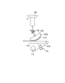
- FIG. 1 It is a figure which shows the process of transcribe
- Drawing 1 is a schematic diagram of pasting device 100 of this embodiment.
- the bonding apparatus 100 of this embodiment bonds the sheet piece F1X obtained by half-cutting the elongate optical member sheet
- optical display component P for example, a panel-shaped optical display component such as a liquid crystal panel or an organic EL panel can be used.
- optical member sheet FX for example, a polarizing film, a retardation film, a brightness enhancement film, or the like can be used. In the present embodiment, for example, a polarizing film shown in FIG. 7 is used as the optical member sheet FX.
- the optical member sheet FX of FIG. 7 includes a film-shaped optical member main body F1a, an adhesive layer F2a provided on one surface (upper surface in FIG. 7) of the optical member main body F1a, and the optical member main body via the adhesive layer F2a.
- the optical member main body F1a functions as a polarizing plate, for example, and is bonded over the entire display area of the optical display component P and its peripheral area.
- the optical member body F1a is bonded to the optical display component P via the adhesive layer F2a in a state where the separator sheet F3a is separated while leaving the adhesive layer F2a on one surface thereof.
- seat FX is called the bonding sheet
- Sheet piece F1X is a sheet piece of bonding sheet F5 obtained by cutting long bonding sheet F5 into a predetermined size.
- the separator sheet F3a protects the adhesive layer F2a and the optical member body F1a before being separated from the adhesive layer F2a.
- the surface protective film F4a is bonded to the optical display component P together with the optical member body F1a.
- the surface protective film F4a is disposed on the side opposite to the optical display component P with respect to the optical member body F1a to protect the optical member body F1a.
- the optical member sheet FX may be configured not to include the surface protective film F4a, or the surface protective film F4a may be separated from the optical member body F1a.
- the optical member body F1a is bonded to the sheet-like polarizer F6, the first film F7 bonded to one surface of the polarizer F6 with an adhesive or the like, and the other surface of the polarizer F6 with an adhesive or the like. And a second film F8.
- the first film F7 and the second film F8 are, for example, protective films that protect the polarizer F6.
- the optical member body F1a may have a single-layer structure composed of a single optical layer, or may have a stacked structure in which a plurality of optical layers are stacked on each other.
- the optical layer may be a retardation film, a brightness enhancement film, or the like.
- At least one of the first film F7 and the second film F8 may be subjected to a surface treatment that provides an effect such as a hard coat treatment for protecting the outermost surface of the liquid crystal display element or an antiglare treatment including an antiglare treatment.
- the optical member body F1a may not include at least one of the first film F7 and the second film F8.
- the separator sheet F3a may be bonded to one surface of the polarizer F6 via the adhesive layer F2a.
- the bonding apparatus 100 includes, for example, a sheet conveyance device 110, a dust collector 10, a head unit 150 (bonding unit), a head moving device 160, and a stage unit 170. And a control device 190.
- the sheet conveying device 110 includes, for example, an unwinding unit 111, a winding unit 112, a nip roll unit 113, a sheet stage 114, and a cutting unit 115.
- the unwinding unit 111 holds the original fabric roll RX around which the long optical member sheet FX is wound, and feeds the optical member sheet FX in the longitudinal direction thereof.
- the optical member sheet FX has a width equivalent to the length of the first side (for example, the short side) of the display area of the optical display component P, for example, in the horizontal direction (sheet width direction) orthogonal to the conveyance direction. .
- the sheet conveying direction the direction in which the optical member sheet FX (separator sheet F3a) is unwound from the unwinding unit 111 and conveyed
- the upstream side in the sheet conveying direction is referred to as the sheet conveying upstream side
- the downstream side in the sheet conveying direction Is referred to as the sheet conveyance downstream side.
- the cutting unit 115 cuts (half-cuts) the optical member sheet FX unwound from the raw roll RX in the thickness direction while leaving the separator sheet F3a.
- the cut portion 115 is, for example, in the length direction in which the optical member sheet FX is orthogonal to the sheet width direction, and has a length equivalent to the length of the second side (for example, the long side) of the display area of the optical display component P.
- a part in the thickness direction of the optical member sheet FX is cut across the entire width in the sheet width direction.
- the cut part 115 adjusts the advancing / retreating position of the cutting blade so that the separator sheet F3a is not broken by the tension acting during the conveyance of the optical member sheet FX (so that a predetermined thickness remains on the separator sheet F3a), and the adhesive layer Half-cut to the vicinity of the interface between F2a and separator sheet F3a.
- a laser cutting device can be used as the cutting portion 115 instead of the cutting blade.
- the optical member sheet FX after the half cut is cut along the entire width in the sheet width direction of the optical member sheet FX by cutting the optical member body F1a, the adhesive layer F2a and the surface protection film F4a in the thickness direction. Is formed.
- the optical member sheet FX is divided into sections having a length corresponding to the length of the second side of the display area in the longitudinal direction by a cutting line. Each of these sections becomes one sheet piece F1X in the bonding sheet F5.
- the cutting angle of the optical member sheet FX with respect to the sheet conveyance direction is controlled by the control device 190.
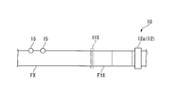
- imaging devices 15 (see FIGS. 2 and 3) that capture the image of the edge of the optical member sheet FX are arranged at a plurality of locations in the sheet conveyance direction, and the images of the edges at the plurality of locations captured by these imaging devices 15 are arranged.
- the control device 190 detects the positions of the plurality of edges. Then, based on the detected relative positional relationship between the plurality of edges, the control device 190 calculates an inclination angle of the edge with respect to the sheet conveyance direction at the cut position of the optical member sheet FX.
- the sheet stage 114 supports the lower surface (the surface on the separator sheet F3a side shown in FIG. 7) of the optical member sheet FX unwound from the original roll RX.
- the sheet stage 114 is provided, for example, from the sheet conveyance downstream side of the dust collection position where dust on the sheet piece F1X is removed to the separation position where the sheet piece F1X is separated from the separator sheet F3a.
- the nip roll unit 113 includes a first nip roll 113a and a second nip roll 113b that are arranged in parallel with each other in the rotation axis direction.
- the first nip roll 113a and the second nip roll 113b rotate in synchronization with each other, thereby separating the separator sheet F3a from the upstream side of the sheet conveyance to the downstream side of the sheet conveyance (in the winding direction of the winding unit 112) and the downstream side of the sheet conveyance To the upstream side of the sheet conveyance (in the unwinding direction from the winding unit 112).
- the winding part 112 winds up the separator sheet F3a which became independent after the sheet piece F1X was peeled from the separator sheet F3a by the bonding head 120.
- the winding unit 112 winds and unwinds the separator sheet F3a by rotating in synchronization with the first nip roll 113a and the second nip roll 113b.
- the dust collector 10 includes a cut position where the optical member sheet FX is half-cut by the cut portion 115 and a peel position where the sheet piece F1X obtained by the half cut is peeled from the separator sheet F3a and held by the bonding head 120. And between. The dust collector 10 removes dust from the sheet piece F1X. Details of the dust collector 10 will be described later.
- the head unit 150 includes, for example, a bonding head 120, a head driving device 130, and a head lifting device 140.
- the bonding head 120 includes, for example, a head main body 121 and an adhesive sheet 122.
- the head main body 121 has a curved surface curved along the traveling direction of the optical member sheet FX so that the upper surface is a flat surface and the lower surface is convex downward.
- An adhesive sheet 122 is fixed to the lower surface of the head main body 121.
- an adhesive silicone rubber is used as the adhesive sheet 122.
- the surface of the pressure-sensitive adhesive sheet 122 is a curved holding surface 122a for attaching and holding the sheet piece F1X.
- the holding surface 122a has, for example, a weaker bonding force than the bonding surface (adhesive layer F2a) of the sheet piece F1X, and the surface protective film F4a of the sheet piece F1X can be repeatedly bonded and peeled off.
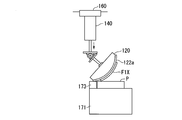
- the laminating head 120 rolls the sheet piece F1X from the separator sheet F3a by rolling along the curve of the holding surface 122a while pressing the curved holding surface 122a against the sheet piece F1X supported on the sheet stage 114. It peels and it hold
- the bonding head 120 rolls along the curvature of the holding surface 122a while pressing the sheet piece F1X held on the holding surface 122a against the optical display component P placed on the bonding stage 171. Is bonded to the optical display component P.
- the head driving device 130 includes, for example, a base plate 135, a rotation driving unit 136, and a rod unit 137.
- the bonding head 120 is connected to the rotation support shaft 136a of the rotation drive unit 136 via a rod part 137 connected to the center of the upper surface of the head main body 121.
- the rotation support shaft 136a is fixed to the base plate 135.
- the bonding head 120 is suspended from the lower surface of the base plate 135 via the rod portion 137 and the rotation support shaft 136a so as to be freely rotatable.
- the holding surface 122a is, for example, an arcuate curved surface with the rotation support shaft 136a as the center.
- the bonding head 120 is rotated by the rotation drive unit 136 around the rotation support shaft 136a within a predetermined angle range. Thereby, sticking of the sheet piece F1X from the separator sheet F3a to the holding surface 122a and bonding (transfer) of the sheet piece F1X from the holding surface 122a to the optical display component P are performed.
- the head lifting / lowering device 140 includes a cylinder body 141 and a cylinder rod 142.
- a first end of the cylinder rod 142 is fixed to the upper surface of the base plate 135, and a second end of the cylinder rod 142 is connected to a piston in the cylinder body 141.
- the piston and cylinder rod 142 in the cylinder main body 141 move in the vertical direction by the pressure of air introduced into the cylinder main body 141. Thereby, the bonding head 120 moves in the vertical direction.
- the head moving device 160 includes a guide rail 161 and a slider 162. An upper end portion of the cylinder body 141 is fixed to the slider 162. As a result, the head unit 150 is suspended vertically from the slider 162.
- the guide rail 161 is provided so as to straddle between the sheet conveying apparatus 110 and the bonding stage 171.
- the slider 162 reciprocates along the guide rail 161. Thereby, the bonding head 120 moves between the peeling position which peels the sheet piece F1X from the separator sheet F3a, and the bonding position which bonds the sheet piece F1X to the optical display component P.
- the head driving device 130, the head lifting device 140, and the head moving device 160 constitute a head driving mechanism that rotationally drives, moves up and down, and moves horizontally.
- the bonding head 120 is driven by the head driving device 130 and the head moving device 160 to rotate and move horizontally, so that the optical display placed on the sheet piece F1X supported by the sheet stage 114 and the bonding stage 171. Roll on part P. Thereby, sticking of the sheet piece F1X from the separator sheet F3a to the holding surface 122a and bonding (transfer) of the sheet piece F1X from the holding surface 122a to the optical display component P are performed.
- the bonding head 120 is horizontally moved in the first movement direction (for example, right direction) by the head movement device 160 while being rotated in the first rotation direction (for example, clockwise direction) by the head driving device 130.
- the holding surface 122a can roll in a first direction from the first end (for example, the left end) toward the second end (for example, the right end).
- the bonding head 120 is rotated in the second rotation direction (for example, counterclockwise direction) by the head driving device 130 and horizontally in the second movement direction (for example, left direction) by the head movement device 160. By moving, it can roll in a second direction from the second end (for example, the right end) of the holding surface 122a toward the first end (for example, the left end).
- the stage unit 170 includes a bonding stage 171, a stage driving device 172, and a contact plate 173.
- the bonding stage 171 has a placement surface 171a on which the optical display component P is placed.
- the bonding stage 171 holds the optical display component P on the mounting surface 171a by sucking the lower surface of the optical display component P (the surface opposite to the surface to be bonded to the sheet piece F1X).
- the contact plate 173 is a plate-shaped or bar-shaped member disposed along one side of the optical display component P.
- the contact plate 173 is fixed on the placement surface 171a.
- the height of the contact plate 173 substantially matches the height of the optical display component P.
- the contact plate 173 is arranged on the upstream side in the rolling direction AFD from the position where the optical display component P is placed.
- the optical display component P is disposed adjacent to the contact plate 173.
- the optical display component P is fixed on the mounting surface 171a in a state where the end portion is in contact with the side surface of the contact plate 173. Thereby, a plane in which the upper surface of the optical display component P and the upper surface of the contact plate 173 are continuous is formed.
- the backing plate 173 can be fixedly disposed at at least two places (first position and second position) on the bonding stage 171.
- the first position is a position on the bonding stage 171 corresponding to the case where the rolling direction AFD is the first direction (for example, the position on the left side of the optical display component P), and the second position is It is a position on the bonding stage 171 corresponding to the case where the rolling direction AFD is set to the second direction (for example, the position on the right side of the optical display component P).
- the bonding head 120 After the holding surface 122 a positioned on the upstream side of the bonding direction ADF from the sheet F ⁇ b> 1 ⁇ / b> X is pressed against the upper surface of the contact plate 173, the bonding head 120 is connected to the upper surface of the contact plate 173 and the optical display component P.
- the sheet piece F1X held on the holding surface 122a is bonded to one surface of the optical display component P by continuously rolling the upper surface of the optical display component P.
- the laminating head 120 is allowed to run outside the optical display component P so that the bonding conditions such as the load and the speed are made uniform throughout the sheet piece F1X. Can do.
- the stage driving device 172 moves the bonding stage 171 in a direction orthogonal to the rolling direction AFD of the bonding head 120 and the rolling direction AFD of the bonding head 120. Moreover, the stage drive device 172 rotates the bonding stage 171 in a horizontal plane. The stage drive device 172 adjusts the relative bonding position between the optical display component P held by the bonding stage 171 and the sheet piece F1X held by the bonding head 120 by driving the bonding stage 171. . Thereby, alignment with the optical display component P and the sheet piece F1X is performed.
- the control device 190 includes a computer system.
- the computer system includes an arithmetic processing unit such as a CPU and a storage unit such as a memory and a hard disk.
- the control device 190 includes an interface capable of executing communication with an external device of the computer system, and comprehensively controls operations of various devices constituting the bonding device 100 and various devices outside the bonding device 100.
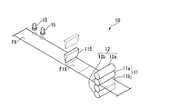
- FIG. 2 is a perspective view of the periphery of the dust collector 10.
- FIG. 3 is a plan view of the periphery of the dust collector 10.
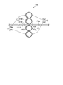
- FIG. 4 is a side view of the dust collector 10.
- the dust collector 10 includes a first roll pair 11 and a second roll pair 12.
- the first roll pair 11 is one roll pair constituted by a pair of first rolls 11a and 11b arranged in parallel with each other in the rotation axis direction.
- first upper roll 11a the first roll disposed on the upper side across the sheet piece F1X
- first lower roll 11b the first roll disposed on the lower side across the sheet piece F1X
- the 1st upper side roll 11a and the 1st lower side roll 11b may be only called a 1st roll, respectively.
- the first upper roll 11a and the first lower roll 11b rotate in synchronization with each other to convey the half-cut optical member sheet FX from the sheet conveying upstream side to the sheet conveying downstream side.
- Each of the first upper roll 11a and the first lower roll 11b is a columnar member having a length larger than the sheet width of the optical member sheet FX.
- Each surface of the 1st upper side roll 11a and the 1st lower side roll 11b has 1st adhesive force As1 which can remove the dust of the sheet piece F1X.
- the first adhesive force As1 is smaller than the adhesive force between the sheet piece F1X and the separator sheet F3a.
- the first adhesive force As1 is smaller than the adhesive force between the optical member main body F1a and the surface protective film F4a constituting the sheet piece F1X. From the same viewpoint, the first adhesive force As1 is determined by the adhesive force between one surface of the polarizer F6 and the first film F7 and the adhesive force between the other surface of the polarizer F6 and the second film F8, respectively. Is also small.
- the first roll pair 11 sandwiches a part of the sheet piece F1X conveyed to the head unit 150 in the conveyance direction from above and below.
- the first roll pair 11 includes a third cut line and a fourth cut line from the upstream side of the sheet conveyance among the four cut lines formed on the optical member sheet FX by the cut portion 115.
- a part of the sheet piece F1X partitioned by is sandwiched from above and below.
- the arrangement position of the first roll pair 11 is not limited to this. If the arrangement position of the first roll pair 11 is between the cut part 115 and the head unit 150, it can be set to a desired position as appropriate.
- the first roll pair 11 removes dust present on the surface of the sheet piece F1X by bringing the surface into contact with the surface of the sheet piece F1X.
- the 1st upper side roll 11a makes the surface contact the surface of the surface protection film F4a which comprises the sheet piece F1X, and removes the dust on the surface of the surface protection film F4a.
- the first lower roll 11b brings the surface into contact with the surface (lower surface) of the separator sheet F3a to remove dust on the surface of the separator sheet F3a.
- the 2nd roll pair 12 is one roll pair comprised by a pair of 2nd rolls 12a and 12b arrange
- the second roll facing the first upper roll 11a is referred to as a second upper roll 12a.
- the second roll facing the first lower roll 11b is referred to as a second lower roll 12b.
- the 2nd upper side roll 12a and the 2nd lower side roll 12b may be only called a 2nd roll, respectively.
- the second upper roll 12a rotates in synchronization with the first upper roll 11a
- the second lower roll 12b can rotate in synchronization with the first lower roll 11b.
- the second upper roll 12a rotates in the rotation direction (clockwise direction) opposite to the rotation direction (counterclockwise direction) of the first upper roll 11a
- the second lower roll 12b The first lower roll 11b rotates in the rotation direction (counterclockwise direction) opposite to the rotation direction (clockwise direction).
- Each of the second upper roll 12a and the second lower roll 12b is a cylindrical member having a length that is approximately equal to the length of the first roll in the sheet width direction.
- the second upper roll 12a and the second lower roll 12b sandwich the first roll pair 11 (first upper roll 11a, first lower roll 11b) from above and below.
- Each surface of the second upper roll 12a and the second lower roll 12b has a second adhesive force Fs2 that is larger than the first adhesive force Fs1 (Fs2> Fs1). Thereby, the dust adhering to the first roll can be removed by the second roll. Therefore, the first adhesive force Fs1 can be effectively maintained.
- the 1st adhesive sheet 13 is wound around the 1st roll pair 11 so that attachment or detachment is possible.
- the first upper pressure-sensitive adhesive sheet 13a is detachably wound around the first upper roll 11a.
- a first lower pressure-sensitive adhesive sheet 13b is detachably wound around the first lower roll 11b.
- the first adhesive force Fs1 is reduced due to the adhesion of dust, it is only necessary to replace the first adhesive sheet 13 without replacing the entire first roll pair 11. Further, only one of the first upper pressure-sensitive adhesive sheet 13a and the first lower pressure-sensitive adhesive sheet 13b may be replaced as necessary. Therefore, the maintenance for maintaining the first adhesive force Fs1 can be performed efficiently.
- a second adhesive sheet 14 is detachably wound around the second roll pair 12. Specifically, the second upper pressure-sensitive adhesive sheet 14a is detachably wound around the second upper roll 12a. A second lower adhesive sheet 14b is detachably wound around the second lower roll 12b.
- the second adhesive force Fs2 is reduced due to the adhesion of dust, it is only necessary to replace the second adhesive sheet 14 without replacing the entire second roll pair 12. Further, only one of the second upper adhesive sheet 14a and the second lower adhesive sheet 14b may be replaced as necessary. Therefore, the maintenance for maintaining the second adhesive force Fs2 can be performed efficiently. Further, if the second adhesive force Fs2 is maintained, the first adhesive force Fs1 is also maintained, which is effective in maintaining the first adhesive force Fs1.
- the first pressure-sensitive adhesive sheet 13 for example, an adhesive silicon-based or urethane-based pressure-sensitive adhesive sheet is used.
- the 2nd adhesive sheet 14 the urethane type adhesive sheet etc. which have adhesive force larger than the adhesive force (1st adhesive force Fs1) of the 1st adhesive sheet 13 are used, for example.
- a silicon-based adhesive sheet is used as the first adhesive sheet 13
- a urethane-based adhesive sheet is used as the second adhesive sheet 14.
- the replacement of the first adhesive sheet 13 is performed to such an extent that the first adhesive force Fs1 is maintained.
- the replacement of the first pressure-sensitive adhesive sheet 13 is performed by confirming the presence or absence of cracks on the surface of the first pressure-sensitive adhesive sheet 13 by visual observation or the like, whereby the pressure-sensitive adhesive force of the first pressure-sensitive adhesive sheet 13 has the first pressure-sensitive adhesive force Fs1. This may be performed when it is determined whether the adhesive force of the first adhesive sheet 13 is likely to be lower than the first adhesive force Fs1.
- the replacement of the second adhesive sheet 14 is performed to such an extent that the second adhesive force Fs2 is maintained.
- the replacement of the first pressure-sensitive adhesive sheet 13 may be performed periodically in consideration of the usage period of the dust collector 10. The same applies to the replacement of the second adhesive sheet 14.
- the bonding method according to the present embodiment is a bonding method of bonding the sheet piece F1X to the optical display component, and includes an unwinding step, a cutting step, a bonding step, and a dust collection step.
- the long optical member sheet FX is unwound together with the separator sheet F3a from the raw fabric roll RX.
- the cutting step forms the sheet piece F1X by cutting the optical member sheet FX leaving the separator sheet F3a.
- the bonding step the sheet piece F1X is peeled off from the separator sheet F3a and bonded to the optical display component.
- dust on the sheet piece F1X is removed between the cutting step and the bonding step, more preferably until the sheet piece F1X is bonded to the holding surface 122a of the bonding head 120.
- the dust collecting step sandwiches a part of the sheet piece F1X conveyed in the bonding step in the conveying direction from above and below, and brings the surface into contact with the surface of the sheet piece F1X.
- the 1st roll pair 11 comprised by a pair of 1st roll 11a, 11b which removes the dust of piece F1X is used.
- Each surface of the first rolls 11a and 11b has a first adhesive force As1 that can remove dust from the sheet piece F1X.
- the dust collecting step is composed of a pair of second rolls 12a and 12b that sandwich the first roll pair 11 from above and below and remove the dust on the first roll by bringing the surface into contact with the first roll pair 11 respectively.
- the second roll pair 12 is used.
- Each surface of the second rolls 12a and 12b has a second adhesive force As2 that is larger than the first adhesive force As1 (As2> As1).
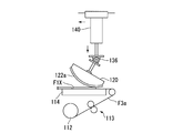
- the bonding head 120 is disposed above the sheet stage 114 while being tilted with respect to the sheet stage 114.
- the conveyance of the sheet piece F1X is stopped, and the sheet piece F1X is stopped on the sheet stage 114.
- the sheet stage 114 supports the sheet piece F1X from the separator sheet F3a side.
- the bonding head 120 and the sheet piece F1X on the sheet stage 114 are positioned.
- the bonding head 120 is inclined so that the upstream side in the rolling direction is positioned below the downstream side in the rolling direction.
- the end of the sheet conveyance downstream side is inclined so as to be positioned below the end of the sheet conveyance upstream side.
- the bonding head 120 will fall to the height which contacts the sheet piece F1X by the head lifting / lowering device 140. Thereby, the edge part of the sheet conveyance downstream of the bonding head 120 is pressed on the edge part of the sheet piece F1X of the sheet conveyance downstream.
- the rotation driving unit 136 and the head moving device 160 are driven in synchronization to roll (rotate) the bonding head 120 from the sheet conveying downstream side to the sheet conveying upstream side. And horizontal movement). Accordingly, the sheet piece F1X is gradually attached to the holding surface 122a from the sheet conveying downstream side to the sheet conveying upstream side.
- the winding unit 112 and the nip roll unit 113 are driven to drive the rotation driving unit 136 and the head moving device 160.
- the separator sheet F3a rotates in the unwinding direction (reverse direction). Thereby, the separator sheet F3a is loosened on the upstream side of the nip roll portion 113, and the sheet piece F1X and the separator sheet F3a on the downstream side of the sheet conveyance from the portion on which the load is applied by the bonding head 120 follow the curvature of the holding surface 122a. And float above the sheet stage 114.
- the separator sheet F3a Since the separator sheet F3a is in a slack state, a force for peeling the sheet piece F1X from the holding surface 122a is unlikely to occur at the end of the sheet piece F1X on the downstream side of the sheet conveyance. Therefore, the adhesive force between the sheet piece F1X and the holding surface 122a is increased, and the sheet piece F1X is reliably attached to the holding surface 122a. Moreover, by loosening the separator sheet F3a, when the sheet piece F1X is peeled from the separator sheet F3a, momentary large peeling force is suppressed from being applied to the separator sheet F3a. Therefore, the separator sheet F3a is suppressed from breaking.
- the winding part 112 and the nip roll part 113 are separated from the separator sheet F3a during the second period until the rolling of the bonding head 120 ends. It rotates in the winding direction (forward direction). Thereby, the slack of the separator sheet F3a is eliminated, and the separation of the sheet piece F1X from the separator sheet F3a is promoted.
- the timing at which the rotation direction of the winding unit 112 and the nip roll unit 113 is switched from the reverse direction to the forward direction is, for example, 5% to 70%, preferably 10% to 50% when the sheet piece F1X is attached to the holding surface 122a. It is assumed that the timing is completed.
- the bonding head 120 While the separator sheet F3a is being unwound and wound by the winding unit 112 and the nip roll unit 113, the bonding head 120 always continues to roll in the same direction by the rotation driving unit 136 and the head moving device 160. The bonding head 120 rolls along the curve of the holding surface 122a while pressing the holding surface 122a against the sheet piece F1X, thereby peeling the sheet piece F1X from the separator sheet F3a and holding it on the holding surface 122a.
- the surface protection film F4a of the sheet piece F1X is sequentially bonded to the holding surface 122a of the bonding head 120.
- the sheet piece F1X attached to the holding surface 122a is peeled from the separator sheet F3a, and the adhesive layer F2a (see FIG. 7: bonding surface with the optical display component P) is exposed.
- the bonding head 120 holding the sheet piece F1X is transferred by the head moving device 160 to the bonding stage 171 on which the optical display component P is placed.
- 5A to 5C show a process of holding the non-defective sheet piece F1X having no defects in the sheet surface to the bonding head 120, but the defective sheet piece F1X having defects in the sheet surface is bonded to the bonding head.
- the same processing is performed when the data is held at 120.
- the bonding head 120 holding the defective sheet piece F ⁇ b> 1 ⁇ / b> X is transferred by the head driving device 160 to an unillustrated discarding position (discard position) arranged at a position different from the bonding stage 171. Then, the defective sheet piece F1X is overlaid on a waste material sheet or the like provided at the disposal position.
- the above-mentioned defects of the sheet piece F1X include, for example, a portion where a foreign substance consisting of at least one of solid, liquid and gas exists inside the sheet piece F1X, and unevenness and scratches on the surface of the sheet piece F1X. And a portion that becomes a bright spot due to distortion of the sheet piece F1X, material deviation, or the like.
- the bonding head 120 holding the sheet piece F1X is raised to a height that does not interfere with the sheet conveying device 110 by the head lifting device 140 with the adhesive layer F2a (see FIG. 7) facing downward. . Then, the bonding head 120 is transferred by the head moving device 160 to a position above the bonding stage 171 on which the optical display component P is placed.
- the bonding head 120 moves from the sheet stage 114 to the bonding stage 171
- four corners of the sheet piece F1X held on the holding surface 122a are imaged by the first imaging device 181.
- the image of the sheet piece F1X captured by the first imaging device 181 is subjected to image analysis by a first image processing device (not shown), and the positions of the four corners of the sheet piece F1X are detected.
- Information regarding the position of the corner of the sheet piece F1X detected by the first image processing device is sent to the control device 190.
- the control device 190 confirms the arrangement position of the sheet piece F1X with respect to the bonding head 120 based on the information detected by the first image processing device.
- the optical display component P held on the bonding stage 171 is imaged by, for example, the second imaging device 182.
- the second imaging device 182 images using an alignment mark or a black matrix provided on the optical display component P as an alignment reference.
- the image of the optical display component P imaged by the second imaging device 182 is image-analyzed by a second image processing device (not shown), and the position of the alignment reference is detected.
- Information regarding the position of the alignment reference of the optical display component P detected by the second image processing device is sent to the control device 190.
- the control device 190 confirms the arrangement position of the optical display component P with respect to the bonding stage 171 based on the information detected by the second image processing device.
- the control device 190 controls the stage driving device 172 based on the arrangement position of the sheet piece F1X with respect to the bonding head 120 and the arrangement position of the optical display component P with respect to the bonding stage 171.
- the control device 190 uses the stage driving device 172 to horizontally move the bonding stage 171 in the horizontal plane or to rotationally drive the bonding stage 171 in the horizontal plane. Thereby, the relative bonding position of the optical display component P hold
- the bonding head 120 when the relative bonding position between the optical display component P and the sheet piece F1X is adjusted, the bonding head 120 is lowered to a height at which the optical display component P comes into contact with the head lifting device 140.
- the bonding head 120 is inclined so that the end on the upstream side in the rolling direction is positioned below the end on the downstream side in the rolling direction.
- the end of the bonding head 120 located on the upstream side in the rolling direction from the sheet piece F1X is the upper surface of the contact plate 173 located on the upstream side in the rolling direction of the optical display component P. Pressed against.
- the rotation driving unit 136 and the head moving device 160 are driven in synchronization, so that the bonding head 120 is rotated from the upper surface of the contact plate 173 toward the upper surface of the optical display component P. Move. Along with the rolling of the bonding head 120, the sheet piece F1X held on the holding surface 122a is gradually attached to the upper surface of the optical display component P.
- the bonding head 120 has, for example, a weaker adhesive force than the bonding surface of the sheet piece F1X (see FIG. 7: adhesive layer F2a), and the surface protection film F4a of the sheet piece F1X can be repeatedly bonded and peeled off. ing. Therefore, the sheet piece F1X whose pressure-sensitive adhesive layer F2a side is pressed by the optical display component P is peeled from the holding surface 122a and bonded to the upper surface of the optical display component P. Thus, the bonding process of the sheet piece F1X to the optical display component P is completed.
- 6A to 6C show a process of transferring a non-defective sheet piece F1X having no defect in the sheet surface from the bonding head 120 to the optical display component P. However, the defective sheet piece having a defect in the sheet surface is shown. The same process is performed when F1X is bonded to a waste material sheet or the like provided at the disposal position.
- the sheet piece F1X and the optical display component P can be bonded in the head unit 150. Bonding can be performed in a state in which the biting of air and generation of bubbles are eliminated. Therefore, product quality can be improved. Moreover, since it is the contact type structure by the 1st roll pair 11, the dust on the surface of the sheet piece F1X can be effectively removed compared with the non-contact type structure.
- the bonding piece 120 rolls along the curve of the holding surface 122a, so that the sheet piece F1X is It peels from the separator sheet F3a and is hold
- the surface of each of the first rolls 11a and 11b has been described with an example having the first adhesive force As1 that can remove the dust on the sheet piece F1X.
- the present invention is not limited to this.
- only the surface of the first upper roll 11a may have the first adhesive force As1, or only the surface of the first lower roll 11b is the first.
- You may have one adhesive strength As1. That is, it is only necessary that at least one surface of the pair of first rolls 11a and 11b has the first adhesive force As1.
- the surfaces of the first rolls 11a and 11b may have the first adhesive force As1. preferable.
- each surface of 2nd roll 12a, 12b has the 2nd adhesive force Fs2 larger than the 1st adhesive force Fs1, it does not restrict to this.
- the first roll having the first adhesive force Fs1 out of the pair of second rolls 12a and 12b. Only the surface of the second roll opposed to may have the second adhesive force Fs2.
- the dust collector 10 has been described by taking the configuration including the first roll pair 11 and the second roll pair 12 as an example, but the present invention is not limited thereto.
- the dust collector may not include the second roll pair 12 but may include only the first roll pair 11. According to this configuration, dust on the surface of the sheet piece F1X can be suppressed while simplifying the device configuration. Further, the first adhesive sheet 13 wound around the first roll pair 11 can be easily attached and detached.
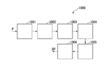
- FIG. 8 is a schematic diagram of an optical display device production system 1000 according to the first embodiment of the present invention.
- the optical display device is configured by bonding an optical member to the optical display component P.
- the production system 1000 includes the above-described bonding device 100 as a bonding device that bonds a sheet piece that is the optical member to the optical display component P.
- the production system 1000 of the present embodiment includes a cleaning device 1001, a first bonding device 1002, a second bonding device 1003, a peeling device 1004, a third bonding device 1005, and an inspection device 1006. .
- the 1st bonding apparatus 1002, the 2nd bonding apparatus 1003, and the 3rd bonding apparatus 1005 have the structure of the bonding apparatus 100 mentioned above.
- the cleaning device 1001, the first bonding device 1002, the second bonding device 1003, the peeling device 1004, the third bonding device 1005, and the inspection device 1006 are a series of conveyance lines that convey the optical display component P. Placed in.
- the cleaning apparatus 1001 cleans the optical display component P carried in from a loader (not shown), and removes foreign matters attached to the optical display component P.
- the cleaning apparatus 1001 is, for example, a first surface (for example, a surface on the side where the image displayed in the display area is viewed) and a second surface (for example, the side where the image displayed on the display area is viewed).
- the surface of the optical display component P is subjected to brushing and rinsing, and then the first surface and the second surface of the optical display component P are drained.
- the cleaning device 1001 may be a dry type that performs static electricity removal and dust collection on the front and back surfaces of the optical display component P.
- the optical display component P is, for example, a liquid crystal panel.
- the first bonding device 1002 bonds the first sheet piece to the first surface of the optical display component P.
- the 1st bonding apparatus 1002 is the dust collection which removes the dust of a 1st sheet piece after the formation of a 1st sheet piece and before bonding with the optical display component P similarly to the bonding apparatus 100 mentioned above. Including the device. Therefore, since the first sheet piece and the optical display component P can be pasted after the dust on the first sheet piece is removed by the dust collector, the pasting is performed in a state in which the dust bites and the generation of bubbles are eliminated. Can do. Therefore, product quality can be improved.
- the 1st bonding apparatus 1002 rolls a bonding head along the curve of a holding surface, pressing the curved holding surface of a bonding head with respect to the stationary 1st sheet piece, A 1st sheet The piece is peeled from the separator sheet and held on the holding surface. For this reason, when the first sheet piece is bonded to the optical display component P, the generation of bubbles between the first sheet piece and the optical display component P is suppressed.
- the first sheet piece is, for example, a sheet-like polarizing plate cut to a size corresponding to the outer dimension of the optical display component P.
- size corresponding to the external dimension of the optical display component P means a size that does not cause a surplus part that causes a problem in actual use when bonded to the optical display component P.
- the first sheet piece has the same configuration as the sheet piece F1X shown in FIG.
- a display area for displaying an image is provided in the center of the optical display component P, and a plurality of terminals to which a semiconductor chip, a flexible printed wiring, and the like are connected are provided at the end of the optical display component P.
- An electrical component mounting portion is provided.
- the first sheet piece is, for example, an area that is not less than the size of the display area of the optical display component P and not more than the size of the outer shape (contour shape in plan view) of the optical display component P and is optical.
- a sheet piece having a size of a region that avoids a functional part such as an electric component mounting portion in the display component P is used.
- the “sheet piece larger than the optical member” in the present application refers to an optical display sheet having an arbitrary size from the display area of the optical display component P to the end of the optical display component P.
- the second bonding apparatus 1003 bonds the second sheet piece to the second surface of the optical display component P. Similarly to the bonding apparatus 100 described above, the second bonding apparatus 1003 removes dust from the second sheet piece after the formation of the second sheet piece and before the bonding with the optical display component P. Including the device. Therefore, after removing the dust on the second sheet piece with the dust collector, the second sheet piece and the optical display component P can be pasted, so that the pasting is performed in a state in which dust is not caught and the generation of bubbles is eliminated. Can do. Therefore, product quality can be improved.
- the 2nd bonding apparatus 1003 rolls a bonding head along the curve of a holding surface, pressing the holding surface where the bonding head curved against the stationary 2nd sheet piece, and 2nd The sheet piece is peeled off from the separator sheet and held on the holding surface. For this reason, when the second sheet piece is bonded to the optical display component P, the generation of bubbles between the second sheet piece and the optical display component P is suppressed.
- the second sheet piece is, for example, a sheet-like polarizing plate cut to a size corresponding to the outer dimension of the optical display component P.
- the second sheet piece has the same configuration as the sheet piece F1X shown in FIG.
- the transmission axis of the second sheet piece bonded to the second surface of the optical display component P and the transmission axis of the first sheet piece bonded to the first surface of the optical display component P are orthogonal to each other.
- the inversion apparatus (illustration omitted) which reverses the front and back of the optical display component P is provided, for example.
- the optical display component P in which the first sheet piece is bonded to the first surface is supplied to the second bonding apparatus 1002 with the front and back sides reversed.
- the peeling apparatus 1004 peels the surface protection film from the second sheet piece bonded to the second surface of the optical display component P.
- the 3rd bonding apparatus 1005 bonds a 3rd sheet piece to the surface of the 2nd sheet piece from which the surface protection film was peeled by the peeling apparatus 1004.
- the 3rd bonding apparatus 1005 removes the dust of a 3rd sheet piece after the formation of a 3rd sheet piece and before bonding with the optical display component P similarly to the bonding apparatus 100 mentioned above. Including the device. Therefore, after removing the dust on the third sheet piece with the dust collector, the third sheet piece and the optical display component P can be pasted, so that the pasting is performed in a state in which dust bites and generation of bubbles are eliminated. Can do. Therefore, product quality can be improved.
- the 3rd bonding apparatus 1005 rolls a bonding head along the curve of a holding surface, pressing the holding surface where the bonding head curved against the stationary 3rd sheet piece, 3rd.
- the sheet piece is peeled off from the separator sheet and held on the holding surface. For this reason, when the third sheet piece is bonded to the optical display component P, the generation of bubbles between the third sheet piece and the optical display component P is suppressed.
- the third sheet piece is, for example, a sheet-like brightness enhancement film cut to a size corresponding to the outer dimension of the optical display component P.
- the brightness enhancement film is a reflective polarizing plate that reflects linearly polarized light orthogonal to the transmission axis.
- the third sheet piece has the same configuration as the sheet piece F1X shown in FIG.
- the transmission axis of the second sheet piece bonded to the second surface of the optical display component P and the transmission axis of the third sheet piece bonded to the second sheet piece are parallel to each other.
- the inspection device 1006 inspects the optical display component P to determine whether or not the positions of the first sheet piece, the second sheet piece, and the third sheet piece are appropriate (the positional deviation is within the tolerance range). .
- the optical display component determined to have an inappropriate position of the first sheet piece, the second sheet piece, or the third sheet piece with respect to the optical display component P is discharged out of the system by a not-shown dispensing means.
- the optical display component on which the first sheet piece, second sheet piece, and third sheet piece are bonded is subjected to incidental measures such as defect inspection (foreign matter inspection, etc.) and mounting of electrical components as necessary. Are shipped as an optical display device DP.
- a bonding apparatus having the same configuration as the bonding apparatus 100 described above is used as the first bonding apparatus 1002, the second bonding apparatus 1003, and the third bonding apparatus 1005. Yes. Therefore, the sheet piece can be bonded in a state where the biting of dust and the generation of bubbles are eliminated, and the optical display device DP with improved product quality can be provided.
- FIG. 9 is a side sectional view of the dust collector 20 according to the first modification of the first embodiment.
- FIG. 10 is an enlarged view of a main part of FIG.
- the difference from the first embodiment is that the dust collector has a non-contact configuration and that the cut portion is a laser cutting device.
- the non-contact type dust collector 20 will be mainly described.
- the same components as those in the first embodiment are denoted by the same reference numerals, and detailed description thereof is omitted.
- the laser cutting device 215 cuts the optical member sheet FX by irradiating the optical member sheet FX with laser light L from the upper side in the orthogonal direction.
- the dust collector 20 includes a suction device 30.
- the suction device 30 includes a dust collection box 31 disposed on the sheet conveyance downstream side of the cutting line SX (corresponding to the cutting line CL described above) of the optical member sheet FX.
- a duct connecting tube CN is provided on the sheet transport downstream side of the dust collection box 31.
- the dust collection box 31 has a hollow rectangular parallelepiped shape, and a front wall 33 located on the cutting line SX side (hereinafter referred to as the front side of the dust collection box 31) in a plan view is disposed along the cutting line SX.
- the dust collection box 31 inclines the lower part of the front wall 33 obliquely forward and downward, and forms an extension part 35 having a triangular shape in cross section in the front edge part of the lower wall 34. Due to the lower portion of the front wall 33 and the extending portion 35 of the lower wall 34, a suction nozzle 36 having a flow path 36 a inclined rearward is formed at the front lower edge portion of the dust collection box 31.
- the suction nozzle 36 opens a suction port 37 over the entire width of the dust collection box 31 in the length direction of the cutting line SX (scanning direction of the laser light L).
- the suction port 37 is disposed close to the cutting line SX from the downstream side of the sheet conveyance.
- the front wall 33 is fixed to the upper wall 38 so that the vertical position can be adjusted, and the vertical width of the suction port 37 can be adjusted by the vertical movement of the front wall 33.
- the inclination angle (the inclination angle of the inclined surface of the extending portion 35, which is the lower surface of the flow path 36a in FIG. 10) ⁇ 1 in a cross-sectional view of the flow path 36a, is approximately 45 ° with respect to the upper surface of the optical member sheet FX. .
- the downstream opening angle (opening angle of the upper and lower surfaces of the flow path 36a) ⁇ 2 in the cross-sectional view of the flow path 36a is set to about 15 °.
- the dust collection box 31 is arranged on the downstream side of the sheet conveyance with respect to the cutting line SX in a plan view with a distance d that does not interfere with the laser light L.
- the suction device 30 does not move during laser cutting, and the distance d is smaller than when the suction device 30 moves during laser cutting, which contributes to downsizing of the suction device 30.
- a support air channel 41 is formed in the lower wall 34 of the dust collection box 31.
- the flow path 41 feeds support air introduced from an introduction port 42 opened to the lower end portion of the rear wall 39 to the outlet port 43 opened to the lower surface of the extension portion 35.
- a thin guide plate 44 is fixed to the lower surface of the front portion of the lower wall 34, and a blowing nozzle 51 that opens in front of the lower wall 34 is formed between the guide plate 44 and the lower wall 34.
- the blowout nozzle 51 forms a blowout port 52 extending over the entire width of the dust collection box 31 just like the suction port 37 just below the suction port 37 of the dust collection box 31.
- the suction device 30 raises the dust collection box 31 to retract from the cutting position, and when performing the suction operation at the cutting position, the dust collection box 31 is lowered.
- the dust collection box 31 is brought into contact with the uppermost surface of the optical member sheet FX that cuts the lower surface of the guide plate 44, and the suction port 37 and the blowout port 52 are disposed on the downstream side and in the vicinity of the cutting line SX. .
- the optical member sheet FX is laser-cut, dust-like decomposition products (fumes) generated by melting and decomposition reactions thereof can be collected by the dust collection box 31.
- the wind pressure at the tip of the suction nozzle 36 is set to 0.1 kPa or more at static pressure, and the wind speed is set to 7 m / s or more.
- the wind pressure and wind speed at the tip of the blowing nozzle 51 are set to be smaller than that of the suction nozzle 36. Therefore, the support air blown out by the blow-out nozzle 51 flows shortly to the suction port 37 side immediately above the blow-out port 52 and is sucked by the suction nozzle 36. By this air flow, fume attachment to the upper surface of the optical member sheet FX is effectively suppressed in the range of the distance d between the suction port 37 and the cutting line SX.
- the support air blown out by the blowout nozzle 51 is warm air, and by giving thermal energy to the fumes that are sublimated, the attachment of fumes to the optical member sheet FX is further suppressed.
- the sheet piece F1X and the optical display component P can be bonded to each other in the head unit 150. Bonding can be performed in a state where generation of bubbles and air bubbles is eliminated. Therefore, product quality can be improved. Moreover, according to this modification, the fume produced by laser processing in the dust collector 20 can be sucked without leakage over the entire length of the cutting line SX. As a result, it is possible to prevent fume from adhering to the product surface and to prevent line contamination due to fume adhering to the product.
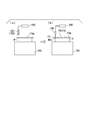
- FIG. 11 is a diagram illustrating a cutting process of the sheet piece FXm in the production system of the present embodiment.
- the difference from the first embodiment is that the sheet piece FXm bonded to the optical display component P by the bonding head is a slightly larger sheet piece than the optical member FO of the target size. And after the sheet piece FXm is bonded to the optical display component P, the excess portion of the sheet piece FXm is cut by the cutting device 184. Therefore, in the following description, it demonstrates centering around the cutting process of the sheet piece FXm.
- the same components as those in the first embodiment are denoted by the same reference numerals, and detailed description thereof is omitted.
- the cross-sectional structure of the sheet piece FXm is the same as that of the sheet piece F1X shown in FIG.
- the sheet piece FXm is obtained by cutting the long optical member sheet FX shown in FIG. 1 into a predetermined size.
- the sheet piece FXm is slightly larger than the size corresponding to the outer dimension of the optical display component P (the size of the first region FB).
- size corresponding to the external dimension of the optical display component P means a size that does not cause a surplus part that causes a problem in actual use when bonded to the optical display component P. Since the sheet piece FXm is larger than the size corresponding to the external dimension of the optical display component P, the surplus portion (second region FS) that causes a problem in actual use is cut by the cutting device 184.
- the laminating apparatus for laminating the sheet piece FXm to the optical display component P is the same as the laminating apparatus 100 described in the first embodiment.
- the detection apparatus 189 and the cutting device 184 are provided on the conveyance line on the downstream side of the bonding apparatus.
- the detection device 189 includes an imaging device 183 that images the optical display component P on which the sheet piece FXm is bonded.
- the detection device 189 detects the cut line WCL of the sheet piece FXm (position where the sheet piece FXm should be cut) based on the imaging data of the imaging device 183.
- the imaging device 183 images the optical display component P from above the optical display component P placed on the cutting stage 185 through the sheet piece FXm.
- the imaging device 183 captures images of four corners of a substrate (for example, a color filter substrate) of the optical display component P to which the sheet piece FXm is bonded.
- the detection device 189 performs image processing on the imaging data to detect the position of the outer peripheral edge of the substrate, and detects the position of the outer peripheral edge as the cut line WCL of the sheet piece FXm.
- the control device 190 controls the cutting device 189 based on the information on the cut line WCL sent from the detection device 189, and cuts the sheet piece FXm along the cut line WCL. Thereby, the first area FB facing the display area of the sheet piece FXm and the second area FS outside the first area FB are separated, and the optical member FO having a target size is cut out from the sheet piece FXm.
- the cut line WCL of the sheet piece FXm is detected for each optical display component P conveyed on the conveyance line. Therefore, even if there is a size variation for each optical display component P, the optical member FO having a size corresponding to the outer dimension of the optical display component P can be reliably cut out from the sheet piece FXm.
- the optical member FO having a desired size is bonded to a desired position of the optical display component P by adopting a window cut method.
- the direction of the optical axis of the sheet piece FXm may deviate from the originally designed direction due to manufacturing errors.
- the direction of the optical axis of the sheet piece FXm (optical member sheet FX) is measured in advance, and the relative bonding position between the sheet piece FXm and the optical display component P can be adjusted based on the measurement result.
- the size of the sheet piece FXm matches the size of the target optical member FO, such adjustment cannot be performed.
- the window cut method the sheet piece FXm larger than the optical member FO is bonded to the optical display component P, and then the excess portion of the sheet piece FXm is cut, and thus such adjustment is possible.
- the bonding position (relative bonding position) of the sheet piece FXm with respect to the optical display component P can be determined as follows.
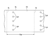
- a plurality of inspection points CP are set in the width direction of the optical member sheet FX, and the direction of the optical axis of the optical member sheet FX is detected at each inspection point CP.
- the timing for detecting the optical axis may be at the time of manufacturing the original fabric roll RX (see FIG. 1), or may be until the optical member sheet FX is unwound from the original fabric roll RX and half-cut.
- Data in the optical axis direction of the optical member sheet FX is stored in a storage device (not shown) in association with the position in the longitudinal direction and the position in the width direction of the optical member sheet FX.
- the control device 190 acquires the optical axis data (inspection data of the in-plane distribution of the optical axis) of each inspection point CP from the storage device, and the optical member sheet FX (cut line CL) of the portion from which the sheet piece FXm is cut out.
- the direction of the average optical axis of the area defined by (1) is detected.
- the shift angle is calculated, for example, with the counterclockwise direction being positive and the clockwise direction being negative with respect to the edge line EL of the sheet piece FXm.
- seat FX detected by said method may make a desired angle with respect to one side of the display area P4 of the optical display component P.
- the bonding position (relative bonding position) of the piece FXm is determined. For example, when the direction of the optical axis of the optical member is set to 90 ° with respect to one side of the display region P4 according to the design specifications, the average optical axis direction of the optical member sheet FX is the display region.
- the sheet piece FXm is bonded to the optical display component P so as to form 90 ° with respect to one side of P4.
- the detection device 189 shown in FIG. 11A detects the cut line WCL of the sheet piece FXm
- the cutting device 184 shown in FIG. 11B detects the sheet piece FXm as the cut line WCL. Is cut along.
- the optical member FO whose direction of the optical axis is precisely controlled is arranged at a desired size and a desired position. Therefore, it is possible to provide a narrow frame optical display device DP having excellent display quality.
- FIG. 13 is a schematic diagram of an optical display device production system 2000 according to the second embodiment of the present invention.
- the production system 2000 is a production system that employs a window cut method.
- the production system 2000 includes the bonding apparatus 100 described in the first embodiment as a bonding apparatus that bonds a sheet piece larger than the optical member to the optical display component P.
- the production system 2000 of the present embodiment includes a cleaning device 2001, a first bonding device 2002, a first cutting device 2003, a second bonding device 2004, a second cutting device 2005, a peeling device 2006, and a first device.
- a three-bonding device 2007, a third cutting device 2008, and an inspection device 2009 are included.
- the cutting device 2008 and the inspection device 2009 are arranged on a series of transport lines that transport the optical display component P.
- the cleaning apparatus 2001, the first bonding apparatus 2002, the second bonding apparatus 2004, the peeling apparatus 2006, the third bonding apparatus 2007, and the inspection apparatus 2009 are the cleaning apparatus 1001 and the first bonding apparatus according to the first embodiment.
- 1002 the 2nd bonding apparatus 1003, the peeling apparatus 1004, the 3rd bonding apparatus 1005, and the test
- the 2nd bonding apparatus 2004, and the 3rd bonding apparatus 2007, a slightly larger sheet piece than the optical member of the objective magnitude
- the first cutting device 2003, the second cutting device 2005, and the third cutting device 2008 have the same configuration as the cutting device 184 and the detection device 189 described above. That is, in the first cutting device 2003, the second cutting device 2005, and the third cutting device 2008, the imaging device picks up an image of the optical display component P on which the sheet piece FXm larger than the optical member having the target size is bonded. Then, a window cut method is employed in which an excess portion of the sheet piece is cut based on the imaging data. Therefore, it is possible to provide a narrow frame optical display device DP having excellent display quality.
- the laminating apparatus the laminating method, the optical display device production system, and the optical display device production method according to the present invention, it is possible to suppress the biting of dust when transferring the sheet piece and to improve the quality of the cocoon product.
- a possible bonding apparatus, a bonding method, an optical display device production system, and an optical display device production method can be provided.
- DESCRIPTION OF SYMBOLS 10,20 ... Dust collector 11 ... First roll pair, 11a ... First upper roll (first roll), 11b ... First lower roll (first roll), 12 ... Second roll pair, 12a ... First Two upper rolls (second roll), 12b ... second lower roll (second roll), 13 ... first adhesive sheet, 14 ... second adhesive sheet, 100 ... laminating device, 111 ... unwinding part, 112 ... Winding part, 114 ... sheet stage, 115 ... cut part, 120 ... bonding head, 122a ... holding surface, 150 ... head unit (bonding part), 171 ... bonding stage, 173 ... plate, 184 ... cutting device DESCRIPTION OF SYMBOLS 189 ...
- Detection apparatus 1000 ... Production system of optical display device, 1002, 1003, 1005 ... Bonding apparatus, 2000 ... Production system of optical display device, 2002, 2004, 2007 ... Bonding apparatus 2003, 2005, 2008 ... Cutting device, DP ... Optical display device, F1X, FXm ... Sheet piece, F3a ... Separator sheet, FO ... Optical member, FX ... Optical member sheet, P ... Optical display component, RX ... Original fabric roll, WCL ... cut line, Fs1 ... first adhesive strength, Fs2 ... second adhesive strength
Landscapes
- Physics & Mathematics (AREA)
- Nonlinear Science (AREA)
- General Physics & Mathematics (AREA)
- Optics & Photonics (AREA)
- Chemical & Material Sciences (AREA)
- Crystallography & Structural Chemistry (AREA)
- Engineering & Computer Science (AREA)
- Theoretical Computer Science (AREA)
- Mathematical Physics (AREA)
- Manufacturing & Machinery (AREA)
- Devices For Indicating Variable Information By Combining Individual Elements (AREA)
- Liquid Crystal (AREA)
- Polarising Elements (AREA)
- Lining Or Joining Of Plastics Or The Like (AREA)
Abstract
Description
本出願は、2014年7月9日に日本に出願された特願2014-141317号に基づき、優先権を主張し、その内容をここに援用する。
特許文献1の装置は、長尺状のシート材を所定サイズにカットしてヘッドに保持する。そして、特許文献1の装置は、ヘッドを被貼付物が載置されたステージに移動させ、ヘッドと被貼付物とを位置決めした後、ヘッドを被貼付物上に押し付けてシート材を被貼付物に転写する。
よって、製品品質を高めることができない。
以下、図1から図8を用いて、本発明の第一の実施の形態に係る貼合装置及び光学表示デバイスの生産システムを説明する。
本実施形態の貼合装置100は、光学表示部品Pの一面に、長尺状の光学部材シートFXをハーフカットして得られたシート片F1Xを貼合する。
ヘッド本体部121は、上面が平坦な面となっており、下面が下側に凸となるように、光学部材シートFXの進行方向に沿って湾曲した曲面となっている。ヘッド本体部121の下面には、粘着シート122が固着される。粘着シート122としては、例えば、粘着性のシリコーンゴムなどが用いられる。粘着シート122の表面は、シート片F1Xを貼着して保持する湾曲した保持面122aとなっている。保持面122aは、例えば、シート片F1Xの貼合面(粘着層F2a)よりも弱い貼着力を有し、シート片F1Xの表面保護フィルムF4aを繰り返し貼着、剥離することが可能とされる。
図2は、集塵装置10の周辺の斜視図である。図3は、集塵装置10の周辺の平面図である。図4は、集塵装置10の側面図である。
以下、一対の第一ロール11a,11bのうち、シート片F1Xを挟んで上側に配置された第一ロールを第一上側ロール11aという。一対の第一ロール11a,11bのうち、シート片F1Xを挟んで下側に配置された第一ロールを第一下側ロール11bという。尚、第一上側ロール11a、第一下側ロール11bを、それぞれ単に第一ロールということがある。
尚、第一ロール対11の配置位置はこれに限らない。第一ロール対11の配置位置は、カット部115とヘッドユニット150との間であれば、適宜所望の位置に設定することができる。
以下、一対の第二ロール12a,12bのうち、第一上側ロール11aと対向する第二ロールを第二上側ロール12aという。一対の第二ロール12a,12bのうち、第一下側ロール11bと対向する第二ロールを第二下側ロール12bという。尚、第二上側ロール12a、第二下側ロール12bを、それぞれ単に第二ロールということがある。
本実施形態に係る貼合方法は、光学表示部品にシート片F1Xを貼合する貼合方法であって、巻き出しステップと、カットステップと、貼合ステップと、集塵ステップと、を含む。
カットステップは、光学部材シートFXを、セパレータシートF3aを残して切断することでシート片F1Xを形成する。
貼合ステップは、シート片F1XをセパレータシートF3aから剥がして光学表示部品に貼合する。
集塵ステップは、カットステップと貼合ステップとの間に、より好ましくはシート片F1Xを貼合ヘッド120の保持面122aに貼着するまでの間に、シート片F1Xの塵埃を除去する。
図2から図4に示すように、集塵ステップは、貼合ステップに搬送されるシート片F1Xの搬送方向における一部を上下から挟み、且つ、表面をシート片F1Xの表面に接触させてシート片F1Xの塵埃を除去する一対の第一ロール11a,11bによって構成される、第一ロール対11を用いる。第一ロール11a,11bのそれぞれの表面は、シート片F1Xの塵埃を除去可能な第一の粘着力As1を有する。
これにより、貼合ステージ171に保持された光学表示部品Pと貼合ヘッド120に保持されたシート片F1Xとの相対貼合位置が調整される。
また、第一ロール対11による接触式の構成であるため、非接触式の構成に比べて、シート片F1Xの表面の塵埃を効果的に除去することができる。
例えば、一対の第一ロール11a,11bのうち、第一上側ロール11aの表面のみが前記第一の粘着力As1を有していてもよいし、第一下側ロール11bの表面のみが前記第一の粘着力As1を有していてもよい。すなわち、一対の第一ロール11a,11bのうち、少なくとも一方の表面が前記第一の粘着力As1を有していればよい。但し、表面保護フィルムF4aの表面及びセパレータシートF3aの表面(下面)のそれぞれの塵埃を除去する観点からは、第一ロール11a,11bのそれぞれの表面が前記第一の粘着力As1を有することが好ましい。
一対の第一ロール11a,11bのうち一方の表面のみが第一の粘着力Fs1を有する場合には、一対の第二ロール12a,12bのうち、前記第一の粘着力Fs1を有する第一ロールと対向する第二ロールの表面のみが、前記第二の粘着力Fs2を有していてもよい。
また、第一貼合装置1002は、静止した第一シート片に対して貼合ヘッドの湾曲した保持面を押し付けながら保持面の湾曲に沿って貼合ヘッドを転動することにより、第一シート片をセパレータシートから剥離して保持面に保持するものである。そのため、第一シート片を光学表示部品Pに貼合する際に、第一シート片と光学表示部品Pとの間に気泡が発生することが抑制される。
また、第二貼合装置1003は、静止した第二シート片に対して貼合ヘッドの湾曲した保持面を押し付けながら、保持面の湾曲に沿って貼合ヘッドを転動することにより、第二シート片をセパレータシートから剥離して保持面に保持するものである。そのため、第二シート片を光学表示部品Pに貼合する際に、第二シート片と光学表示部品Pとの間に気泡が発生することが抑制される。
また、第三貼合装置1005は、静止した第三シート片に対して貼合ヘッドの湾曲した保持面を押し付けながら、保持面の湾曲に沿って貼合ヘッドを転動することにより、第三シート片をセパレータシートから剥離して保持面に保持するものである。そのため、第三シート片を光学表示部品Pに貼合する際に、第三シート片と光学表示部品Pとの間に気泡が発生することが抑制される。
以下、図9及び図10を用いて、第一の実施の形態の第一の変形例に係る集塵装置20を説明する。
図9は、第一の実施の形態の第一の変形例に係る集塵装置20の側断面図である。図10は、図9の要部拡大図である。
また、本変形例によれば、集塵装置20でレーザー加工によって生じるヒュームを、切断線SXの全長に亘って漏れなく吸引することができる。これにより、製品表面へのヒュームの付着を抑えると共に、製品に付着したヒュームによるライン汚染を防ぐことができる。
以下、図11から図13を用いて、本発明の第二の実施の形態に係る貼合装置及び光学表示デバイスの生産システムを説明する。
Claims (22)
- 光学表示部品にシート片を貼合する貼合装置であって、
光学部材シートを原反ロールからセパレータシートと共に巻き出す巻き出し部と、
前記光学部材シートを、前記セパレータシートを残存させながら切断することで前記シート片を形成するカット部と、
前記シート片を前記セパレータシートから剥がして前記光学表示部品に貼合する貼合部と、
前記カット部と前記貼合部との間に配置され、前記シート片の塵埃を除去する集塵装置と、
を含む貼合装置。 - 前記集塵装置は、前記貼合部に搬送される前記シート片の搬送方向における一部を上下から挟み、且つ、表面を前記シート片の表面に接触させて前記シート片の塵埃を除去する一対の第一ロールによって構成される第一ロール対を含み、
前記一対の第一ロールのうち、少なくとも一方の表面は、前記シート片の塵埃を除去可能な第一の粘着力を有する
請求項1に記載の貼合装置。 - 前記第一の粘着力は、前記シート片と前記セパレータシートとの粘着力よりも小さい
請求項2に記載の貼合装置。 - 前記第一の粘着力を有する前記第一ロールには、第一粘着シートが着脱可能に巻回されている
請求項2又は3に記載の貼合装置。 - 前記集塵装置は、前記第一ロール対を上下から挟み、且つ、表面を前記第一ロール対に各々接触させて前記第一ロールの塵埃を除去する一対の第二ロールによって構成される第二ロール対を含み、
前記一対の第二ロールのうち、前記第一の粘着力を有する前記第一ロールと対向する前記第二ロールの表面は、前記第一の粘着力よりも大きい第二の粘着力を有する
請求項2から4までの何れか一項に記載の貼合装置。 - 前記第二の粘着力を有する前記第二ロールには、第二粘着シートが着脱可能に巻回されている
請求項5に記載の貼合装置。 - 前記シート片を前記セパレータシート側から支持するシートステージと、
前記光学表示部品が載置される貼合ステージと、を含み、
前記貼合部は、前記シートステージ上に静止した前記シート片に対して湾曲した保持面を押し付けながら、前記保持面の湾曲に沿って転動することにより、前記シート片を前記セパレータシートから剥離して前記保持面に保持するとともに、前記保持面に保持した前記シート片を、前記貼合ステージに載置された前記光学表示部品に貼合する貼合ヘッドを含む
請求項1から6までの何れか一項に記載の貼合装置。 - 前記貼合ヘッドによって前記セパレータシートから前記シート片が剥離された後、単独となった前記セパレータシートを巻き取る巻き取り部を含み、
前記巻き取り部は、前記貼合ヘッドが前記保持面を前記シート片に押し付けて転動を開始した直後の第一の期間は、前記セパレータシートを巻き解く方向に回転し、前記第一の期間が経過した後、前記転動が終了するまでの第二の期間は、前記セパレータシートを巻き取る方向に回転する
請求項7に記載の貼合装置。 - 前記貼合ステージ上には、前記光学表示部品と隣接するように当て板が備えられ、
前記貼合ヘッドは、前記保持面が前記当て板の上面に押し付けられた後、前記当て板の上面及び前記光学表示部品の上面を連続的に転動することにより、前記保持面に保持した前記シート片を前記光学表示部品に貼合する
請求項7又は8に記載の貼合装置。 - 光学表示部品に光学部材を貼合してなる光学表示デバイスの生産システムであって、
前記光学表示部品に前記光学部材であるシート片を貼合する貼合装置を含み、
前記貼合装置は、請求項1から9までの何れか一項に記載の貼合装置である
光学表示デバイスの生産システム。 - 光学表示部品に光学部材を貼合してなる光学表示デバイスの生産システムであって、
前記光学表示部品に前記光学部材よりも大きいシート片を貼合する貼合装置と、
前記シート片が貼合された前記光学表示部品を撮像し、その撮像データに基づいて、前記シート片のカットラインを検出する検出装置と、
前記光学表示部品に貼合された前記シート片を前記カットラインに沿って切断することにより、前記シート片から前記光学部材を切り出す切断装置と、
を含み、
前記貼合装置は、請求項1から9までの何れか一項に記載の貼合装置である
光学表示デバイスの生産システム。 - 光学表示部品にシート片を貼合する貼合方法であって、
光学部材シートを原反ロールからセパレータシートと共に巻き出す巻き出しステップと、
前記光学部材シートを、前記セパレータシートを残存させながら切断することで前記シート片を形成するカットステップと、
前記シート片を前記セパレータシートから剥がして前記光学表示部品に貼合する貼合ステップと、
前記カットステップと前記貼合ステップとの間に、前記シート片の塵埃を除去する集塵ステップと、
を含む貼合方法。 - 前記集塵ステップは、前記貼合ステップに搬送される前記シート片の搬送方向における一部を上下から挟み、且つ、表面を前記シート片の表面に接触させて前記シート片の塵埃を除去する一対の第一ロールによって構成される第一ロール対を用い、
前記一対の第一ロールのうち、少なくとも一方の表面は、前記シート片の塵埃を除去可能な第一の粘着力を有する
請求項12に記載の貼合方法。 - 前記第一の粘着力は、前記シート片と前記セパレータシートとの粘着力よりも小さい
請求項13に記載の貼合方法。 - 前記第一の粘着力を有する前記第一ロールには、第一粘着シートが着脱可能に巻回されている
請求項13又は14に記載の貼合方法。 - 前記集塵ステップは、前記第一ロール対を上下から挟み、且つ、表面を前記第一ロール対に各々接触させて前記第一ロールの塵埃を除去する一対の第二ロールによって構成される第二ロール対を用い、
前記一対の第二ロールのうち、前記第一の粘着力を有する前記第一ロールと対向する前記第二ロールの表面は、前記第一の粘着力よりも大きい第二の粘着力を有する
請求項13から15までの何れか一項に記載の貼合方法。 - 前記第二の粘着力を有する前記第二ロールには、第二粘着シートが着脱可能に巻回されている
請求項16に記載の貼合方法。 - 前記シート片をシートステージによって前記セパレータシート側から支持する支持ステップと、
前記光学表示部品を貼合ステージに載置する載置ステップと、を含み、
前記貼合ステップは、前記シートステージ上に静止した前記シート片に対して貼合ヘッドの湾曲した保持面を押し付けながら、前記保持面の湾曲に沿って前記貼合ヘッドを転動することにより、前記シート片を前記セパレータシートから剥離して前記保持面に保持するとともに、前記保持面に保持した前記シート片を、前記貼合ステージに載置された前記光学表示部品に貼合する
請求項12から17までの何れか一項に記載の貼合方法。 - 前記貼合ヘッドによって前記セパレータシートから前記シート片が剥離された後、単独となった前記セパレータシートを巻き取り部によって巻き取る巻き取りステップを含み、
前記巻き取りステップでは、前記貼合ヘッドが前記保持面を前記シート片に押し付けて転動を開始した直後の第一の期間は、前記巻き取り部を、前記セパレータシートを巻き解く方向に回転し、前記第一の期間が経過した後、前記転動が終了するまでの第二の期間は、前記巻き取り部を、前記セパレータシートを巻き取る方向に回転する
請求項18に記載の貼合方法。 - 前記貼合ステージ上には、前記光学表示部品と隣接するように当て板が備えられ、
前記貼合ステップでは、前記貼合ヘッドの前記保持面が前記当て板の上面に押し付けられた後、前記貼合ヘッドが前記当て板の上面及び前記光学表示部品の上面を連続的に転動することにより、前記保持面に保持した前記シート片が前記光学表示部品に貼合される
請求項18又は19に記載の貼合方法。 - 光学表示部品に光学部材を貼合してなる光学表示デバイスの生産方法であって、
前記光学表示部品に前記光学部材であるシート片を貼合する貼合ステップを含み、
前記貼合ステップは、請求項12から20までの何れか一項に記載の貼合方法を用いて行われる
光学表示デバイスの生産方法。 - 光学表示部品に光学部材を貼合してなる光学表示デバイスの生産方法であって、
前記光学表示部品に前記光学部材よりも大きいシート片を貼合する貼合ステップと、
前記シート片が貼合された前記光学表示部品を撮像し、その撮像データに基づいて、前記シート片のカットラインを検出する検出ステップと、
前記光学表示部品に貼合された前記シート片を前記カットラインに沿って切断することにより、前記シート片から前記光学部材を切り出す切断ステップと、
を含み、
前記貼合ステップは、請求項12から20までの何れか一項に記載の貼合方法を用いて行われる
光学表示デバイスの生産方法。
Priority Applications (2)
| Application Number | Priority Date | Filing Date | Title |
|---|---|---|---|
| CN201580036760.0A CN106663393B (zh) | 2014-07-09 | 2015-07-03 | 贴合装置、贴合方法、光学显示器件的生产系统以及光学显示器件的生产方法 |
| KR1020177000345A KR102189770B1 (ko) | 2014-07-09 | 2015-07-03 | 접합 장치, 접합 방법, 광학 표시 장치의 생산 시스템 및 광학 표시 장치의 생산 방법 |
Applications Claiming Priority (2)
| Application Number | Priority Date | Filing Date | Title |
|---|---|---|---|
| JP2014141317A JP6401526B2 (ja) | 2014-07-09 | 2014-07-09 | 貼合装置、貼合方法、光学表示デバイスの生産システム及び光学表示デバイスの生産方法 |
| JP2014-141317 | 2014-07-09 |
Publications (1)
| Publication Number | Publication Date |
|---|---|
| WO2016006547A1 true WO2016006547A1 (ja) | 2016-01-14 |
Family
ID=55064183
Family Applications (1)
| Application Number | Title | Priority Date | Filing Date |
|---|---|---|---|
| PCT/JP2015/069279 Ceased WO2016006547A1 (ja) | 2014-07-09 | 2015-07-03 | 貼合装置、貼合方法、光学表示デバイスの生産システム及び光学表示デバイスの生産方法 |
Country Status (5)
| Country | Link |
|---|---|
| JP (1) | JP6401526B2 (ja) |
| KR (1) | KR102189770B1 (ja) |
| CN (1) | CN106663393B (ja) |
| TW (1) | TWI656033B (ja) |
| WO (1) | WO2016006547A1 (ja) |
Families Citing this family (6)
| Publication number | Priority date | Publication date | Assignee | Title |
|---|---|---|---|---|
| CN107808595B (zh) * | 2016-09-08 | 2020-04-21 | 名硕电脑(苏州)有限公司 | 显示屏幕的贴合装置 |
| WO2019064532A1 (ja) * | 2017-09-29 | 2019-04-04 | シャープ株式会社 | 表示素子の製造方法 |
| CN108252074A (zh) * | 2018-01-09 | 2018-07-06 | 广州市画尔服饰有限公司 | 衣料的粘合方法和装置、机器设备、计算机可读存储介质 |
| CN109590971B (zh) * | 2018-12-29 | 2023-10-20 | 昆山拓誉自动化科技有限公司 | 画线装置及画线方法 |
| KR102463088B1 (ko) * | 2019-01-11 | 2022-11-02 | 동우 화인켐 주식회사 | 광학 필름 접합 방법 및 접합 장치 |
| KR102487601B1 (ko) * | 2022-01-14 | 2023-01-12 | 한원물산 주식회사 | 원단과 한지를 합지한 합지원단 제조방법 |
Citations (11)
| Publication number | Priority date | Publication date | Assignee | Title |
|---|---|---|---|---|
| JPH0798348A (ja) * | 1993-09-29 | 1995-04-11 | Sharp Corp | 液晶表示装置の検査装置 |
| JPH0887007A (ja) * | 1994-09-19 | 1996-04-02 | Ookubo Seisakusho:Kk | 偏光板の貼り付け装置 |
| JPH08197026A (ja) * | 1995-01-24 | 1996-08-06 | Nec Eng Ltd | 板のクリーニング機構 |
| JP2000084514A (ja) * | 1998-09-08 | 2000-03-28 | Reyoon Kogyo:Kk | 基板又はシート表面洗浄における加圧制御機構及びこの機構を具える基板又はシート表面洗浄装置 |
| JP4054359B2 (ja) * | 2004-07-02 | 2008-02-27 | シャープ株式会社 | フィルム剥離方法と装置 |
| WO2008143042A1 (ja) * | 2007-05-16 | 2008-11-27 | Nitto Denko Corporation | レーザー加工方法及びレーザー加工品 |
| JP2009063626A (ja) * | 2007-09-04 | 2009-03-26 | Nec Lcd Technologies Ltd | 真空吸着制御機構装置、フィルム貼付装置、フィルムの貼付方法、表示装置 |
| JP2009061498A (ja) * | 2006-10-17 | 2009-03-26 | Nitto Denko Corp | 光学部材貼合せ方法およびそれを用いた装置 |
| JP2013024956A (ja) * | 2011-07-19 | 2013-02-04 | Nitto Denko Corp | 液晶表示素子の連続製造方法及び装置 |
| JP2013095123A (ja) * | 2011-11-05 | 2013-05-20 | Nlt Technologies Ltd | 光学シート貼り合わせ方法及び装置並びにそれらに用いる粘着シート |
| WO2013151035A1 (ja) * | 2012-04-03 | 2013-10-10 | 住友化学株式会社 | 光学表示デバイスの生産システム |
Family Cites Families (10)
| Publication number | Priority date | Publication date | Assignee | Title |
|---|---|---|---|---|
| CN87102577A (zh) * | 1987-04-04 | 1988-10-19 | 赫尔克里斯有限公司 | 任意调节过滤条密度和耐抽性的方法和装置 |
| DE4137349A1 (de) * | 1991-11-13 | 1993-05-19 | Windmoeller & Hoelscher | Vorrichtung zum aufbringen vorzugsweise beleimter zettel oder schlauchstuecke auf eine laufende bahn oderauf durchlaufende werkstuecke |
| JP3004532B2 (ja) * | 1994-04-22 | 2000-01-31 | シャープ株式会社 | 液晶表示素子用フィルムの貼付装置 |
| US6237176B1 (en) * | 1998-09-08 | 2001-05-29 | Rayon Industrial Co., Ltd. | Substrate or sheet surface cleaning apparatus |
| JP4233204B2 (ja) * | 2000-08-22 | 2009-03-04 | 富士フイルム株式会社 | 感光性積層材料の製造方法及び製造装置 |
| JP4482757B2 (ja) * | 2005-01-19 | 2010-06-16 | Jpテック株式会社 | シート材貼付装置 |
| JP2007033821A (ja) * | 2005-07-26 | 2007-02-08 | Optrex Corp | 表示装置製造用位置決めテーブル |
| JP2009163150A (ja) * | 2008-01-09 | 2009-07-23 | Sharp Corp | 光学シート積層体およびバックライトユニットの製造方法、該製造方法で得られる光学シート積層体およびバックライトユニット、および光学シート積層装置 |
| JP4388986B2 (ja) * | 2008-03-19 | 2009-12-24 | シャープ株式会社 | シート積層体の清掃装置およびシート積層体の清掃方法 |
| JP2010150372A (ja) | 2008-12-25 | 2010-07-08 | Sekisui Chem Co Ltd | フィルムの表面処理方法及び装置並びに偏光板の製造方法 |
-
2014
- 2014-07-09 JP JP2014141317A patent/JP6401526B2/ja not_active Expired - Fee Related
-
2015
- 2015-07-03 TW TW104121769A patent/TWI656033B/zh not_active IP Right Cessation
- 2015-07-03 WO PCT/JP2015/069279 patent/WO2016006547A1/ja not_active Ceased
- 2015-07-03 KR KR1020177000345A patent/KR102189770B1/ko not_active Expired - Fee Related
- 2015-07-03 CN CN201580036760.0A patent/CN106663393B/zh not_active Expired - Fee Related
Patent Citations (11)
| Publication number | Priority date | Publication date | Assignee | Title |
|---|---|---|---|---|
| JPH0798348A (ja) * | 1993-09-29 | 1995-04-11 | Sharp Corp | 液晶表示装置の検査装置 |
| JPH0887007A (ja) * | 1994-09-19 | 1996-04-02 | Ookubo Seisakusho:Kk | 偏光板の貼り付け装置 |
| JPH08197026A (ja) * | 1995-01-24 | 1996-08-06 | Nec Eng Ltd | 板のクリーニング機構 |
| JP2000084514A (ja) * | 1998-09-08 | 2000-03-28 | Reyoon Kogyo:Kk | 基板又はシート表面洗浄における加圧制御機構及びこの機構を具える基板又はシート表面洗浄装置 |
| JP4054359B2 (ja) * | 2004-07-02 | 2008-02-27 | シャープ株式会社 | フィルム剥離方法と装置 |
| JP2009061498A (ja) * | 2006-10-17 | 2009-03-26 | Nitto Denko Corp | 光学部材貼合せ方法およびそれを用いた装置 |
| WO2008143042A1 (ja) * | 2007-05-16 | 2008-11-27 | Nitto Denko Corporation | レーザー加工方法及びレーザー加工品 |
| JP2009063626A (ja) * | 2007-09-04 | 2009-03-26 | Nec Lcd Technologies Ltd | 真空吸着制御機構装置、フィルム貼付装置、フィルムの貼付方法、表示装置 |
| JP2013024956A (ja) * | 2011-07-19 | 2013-02-04 | Nitto Denko Corp | 液晶表示素子の連続製造方法及び装置 |
| JP2013095123A (ja) * | 2011-11-05 | 2013-05-20 | Nlt Technologies Ltd | 光学シート貼り合わせ方法及び装置並びにそれらに用いる粘着シート |
| WO2013151035A1 (ja) * | 2012-04-03 | 2013-10-10 | 住友化学株式会社 | 光学表示デバイスの生産システム |
Also Published As
| Publication number | Publication date |
|---|---|
| CN106663393A (zh) | 2017-05-10 |
| TW201605634A (zh) | 2016-02-16 |
| CN106663393B (zh) | 2020-09-29 |
| JP6401526B2 (ja) | 2018-10-10 |
| JP2016018105A (ja) | 2016-02-01 |
| KR20170029492A (ko) | 2017-03-15 |
| TWI656033B (zh) | 2019-04-11 |
| KR102189770B1 (ko) | 2020-12-11 |
Similar Documents
| Publication | Publication Date | Title |
|---|---|---|
| CN101809486B (zh) | 光学显示装置的制造系统及制造方法 | |
| JP6397667B2 (ja) | 貼合装置、貼合方法、光学表示デバイスの生産システムおよび光学表示デバイスの生産方法 | |
| JP6401526B2 (ja) | 貼合装置、貼合方法、光学表示デバイスの生産システム及び光学表示デバイスの生産方法 | |
| CN102837437B (zh) | 光学部件贴合方法以及使用该方法的装置 | |
| CN101840096B (zh) | 液晶显示元件的制造方法 | |
| JP5724152B1 (ja) | 光学表示デバイスの生産システム | |
| JP6403456B2 (ja) | 貼合装置、貼合方法、光学表示デバイスの生産システムおよび光学表示デバイスの生産方法 | |
| JP5724147B2 (ja) | 光学表示デバイスの生産システム | |
| CN106536355B (zh) | 贴合装置、贴合方法、光学显示器件的生产系统及方法 | |
| JP6346505B2 (ja) | 貼合装置、貼合方法、光学表示デバイスの生産システムおよび光学表示デバイスの生産方法 | |
| JP2014186287A (ja) | 光学表示デバイスの生産システム及び生産方法 | |
| TWI476476B (zh) | A continuous manufacturing system of a liquid crystal display device, and a continuous manufacturing method of a liquid crystal display device | |
| JP2014157344A (ja) | 光学表示デバイスの生産システム | |
| JP2016114481A (ja) | 評価装置及び評価方法 |
Legal Events
| Date | Code | Title | Description |
|---|---|---|---|
| 121 | Ep: the epo has been informed by wipo that ep was designated in this application |
Ref document number: 15818331 Country of ref document: EP Kind code of ref document: A1 |
|
| ENP | Entry into the national phase |
Ref document number: 20177000345 Country of ref document: KR Kind code of ref document: A |
|
| WWE | Wipo information: entry into national phase |
Ref document number: 1020177000345 Country of ref document: KR |
|
| NENP | Non-entry into the national phase |
Ref country code: DE |
|
| 122 | Ep: pct application non-entry in european phase |
Ref document number: 15818331 Country of ref document: EP Kind code of ref document: A1 |