WO2016006485A1 - Appareil d'éclairage à lampe à décharge - Google Patents
Appareil d'éclairage à lampe à décharge Download PDFInfo
- Publication number
- WO2016006485A1 WO2016006485A1 PCT/JP2015/068615 JP2015068615W WO2016006485A1 WO 2016006485 A1 WO2016006485 A1 WO 2016006485A1 JP 2015068615 W JP2015068615 W JP 2015068615W WO 2016006485 A1 WO2016006485 A1 WO 2016006485A1
- Authority
- WO
- WIPO (PCT)
- Prior art keywords
- pulse
- frequency
- applied voltage
- discharge lamp
- value
- Prior art date
Links
Images


Classifications
-
- H—ELECTRICITY
- H05—ELECTRIC TECHNIQUES NOT OTHERWISE PROVIDED FOR
- H05B—ELECTRIC HEATING; ELECTRIC LIGHT SOURCES NOT OTHERWISE PROVIDED FOR; CIRCUIT ARRANGEMENTS FOR ELECTRIC LIGHT SOURCES, IN GENERAL
- H05B41/00—Circuit arrangements or apparatus for igniting or operating discharge lamps
- H05B41/14—Circuit arrangements
- H05B41/36—Controlling
-
- G—PHYSICS
- G03—PHOTOGRAPHY; CINEMATOGRAPHY; ANALOGOUS TECHNIQUES USING WAVES OTHER THAN OPTICAL WAVES; ELECTROGRAPHY; HOLOGRAPHY
- G03B—APPARATUS OR ARRANGEMENTS FOR TAKING PHOTOGRAPHS OR FOR PROJECTING OR VIEWING THEM; APPARATUS OR ARRANGEMENTS EMPLOYING ANALOGOUS TECHNIQUES USING WAVES OTHER THAN OPTICAL WAVES; ACCESSORIES THEREFOR
- G03B21/00—Projectors or projection-type viewers; Accessories therefor
- G03B21/14—Details
- G03B21/20—Lamp housings
- G03B21/2006—Lamp housings characterised by the light source
- G03B21/2026—Gas discharge type light sources, e.g. arcs
-
- G—PHYSICS
- G03—PHOTOGRAPHY; CINEMATOGRAPHY; ANALOGOUS TECHNIQUES USING WAVES OTHER THAN OPTICAL WAVES; ELECTROGRAPHY; HOLOGRAPHY
- G03B—APPARATUS OR ARRANGEMENTS FOR TAKING PHOTOGRAPHS OR FOR PROJECTING OR VIEWING THEM; APPARATUS OR ARRANGEMENTS EMPLOYING ANALOGOUS TECHNIQUES USING WAVES OTHER THAN OPTICAL WAVES; ACCESSORIES THEREFOR
- G03B21/00—Projectors or projection-type viewers; Accessories therefor
- G03B21/14—Details
- G03B21/20—Lamp housings
- G03B21/2053—Intensity control of illuminating light
-
- H—ELECTRICITY
- H01—ELECTRIC ELEMENTS
- H01J—ELECTRIC DISCHARGE TUBES OR DISCHARGE LAMPS
- H01J61/00—Gas-discharge or vapour-discharge lamps
- H01J61/84—Lamps with discharge constricted by high pressure
- H01J61/86—Lamps with discharge constricted by high pressure with discharge additionally constricted by close spacing of electrodes, e.g. for optical projection
-
- H—ELECTRICITY
- H05—ELECTRIC TECHNIQUES NOT OTHERWISE PROVIDED FOR
- H05B—ELECTRIC HEATING; ELECTRIC LIGHT SOURCES NOT OTHERWISE PROVIDED FOR; CIRCUIT ARRANGEMENTS FOR ELECTRIC LIGHT SOURCES, IN GENERAL
- H05B41/00—Circuit arrangements or apparatus for igniting or operating discharge lamps
- H05B41/14—Circuit arrangements
- H05B41/24—Circuit arrangements in which the lamp is fed by high frequency ac, or with separate oscillator frequency
-
- H—ELECTRICITY
- H05—ELECTRIC TECHNIQUES NOT OTHERWISE PROVIDED FOR
- H05B—ELECTRIC HEATING; ELECTRIC LIGHT SOURCES NOT OTHERWISE PROVIDED FOR; CIRCUIT ARRANGEMENTS FOR ELECTRIC LIGHT SOURCES, IN GENERAL
- H05B41/00—Circuit arrangements or apparatus for igniting or operating discharge lamps
- H05B41/14—Circuit arrangements
- H05B41/26—Circuit arrangements in which the lamp is fed by power derived from dc by means of a converter, e.g. by high-voltage dc
- H05B41/28—Circuit arrangements in which the lamp is fed by power derived from dc by means of a converter, e.g. by high-voltage dc using static converters
- H05B41/288—Circuit arrangements in which the lamp is fed by power derived from dc by means of a converter, e.g. by high-voltage dc using static converters with semiconductor devices and specially adapted for lamps without preheating electrodes, e.g. for high-intensity discharge lamps, high-pressure mercury or sodium lamps or low-pressure sodium lamps
- H05B41/2885—Static converters especially adapted therefor; Control thereof
- H05B41/2887—Static converters especially adapted therefor; Control thereof characterised by a controllable bridge in the final stage
- H05B41/2888—Static converters especially adapted therefor; Control thereof characterised by a controllable bridge in the final stage the bridge being commutated at low frequency, e.g. 1kHz
-
- H—ELECTRICITY
- H05—ELECTRIC TECHNIQUES NOT OTHERWISE PROVIDED FOR
- H05B—ELECTRIC HEATING; ELECTRIC LIGHT SOURCES NOT OTHERWISE PROVIDED FOR; CIRCUIT ARRANGEMENTS FOR ELECTRIC LIGHT SOURCES, IN GENERAL
- H05B41/00—Circuit arrangements or apparatus for igniting or operating discharge lamps
- H05B41/14—Circuit arrangements
- H05B41/26—Circuit arrangements in which the lamp is fed by power derived from dc by means of a converter, e.g. by high-voltage dc
- H05B41/28—Circuit arrangements in which the lamp is fed by power derived from dc by means of a converter, e.g. by high-voltage dc using static converters
- H05B41/288—Circuit arrangements in which the lamp is fed by power derived from dc by means of a converter, e.g. by high-voltage dc using static converters with semiconductor devices and specially adapted for lamps without preheating electrodes, e.g. for high-intensity discharge lamps, high-pressure mercury or sodium lamps or low-pressure sodium lamps
- H05B41/292—Arrangements for protecting lamps or circuits against abnormal operating conditions
- H05B41/2928—Arrangements for protecting lamps or circuits against abnormal operating conditions for protecting the lamp against abnormal operating conditions
-
- H—ELECTRICITY
- H05—ELECTRIC TECHNIQUES NOT OTHERWISE PROVIDED FOR
- H05B—ELECTRIC HEATING; ELECTRIC LIGHT SOURCES NOT OTHERWISE PROVIDED FOR; CIRCUIT ARRANGEMENTS FOR ELECTRIC LIGHT SOURCES, IN GENERAL
- H05B41/00—Circuit arrangements or apparatus for igniting or operating discharge lamps
- H05B41/14—Circuit arrangements
- H05B41/36—Controlling
- H05B41/38—Controlling the intensity of light
-
- Y—GENERAL TAGGING OF NEW TECHNOLOGICAL DEVELOPMENTS; GENERAL TAGGING OF CROSS-SECTIONAL TECHNOLOGIES SPANNING OVER SEVERAL SECTIONS OF THE IPC; TECHNICAL SUBJECTS COVERED BY FORMER USPC CROSS-REFERENCE ART COLLECTIONS [XRACs] AND DIGESTS
- Y02—TECHNOLOGIES OR APPLICATIONS FOR MITIGATION OR ADAPTATION AGAINST CLIMATE CHANGE
- Y02B—CLIMATE CHANGE MITIGATION TECHNOLOGIES RELATED TO BUILDINGS, e.g. HOUSING, HOUSE APPLIANCES OR RELATED END-USER APPLICATIONS
- Y02B20/00—Energy efficient lighting technologies, e.g. halogen lamps or gas discharge lamps
Definitions
- the present invention relates to a discharge lamp lighting device suitably used for a light source such as a projector.
- a high mercury vapor pressure discharge lamp is used as the light source of the projector device.
- Such a high-pressure mercury lamp can obtain light in the visible wavelength region with high output by increasing the mercury vapor pressure.
- the discharge lamp has a substantially spherical light-emitting portion formed by a discharge vessel, and a pair of electrodes are arranged facing each other at a very small interval of, for example, 2 mm or less in this light-emitting portion.
- a plurality of minute protrusions may be formed at a high temperature, or minute irregularities may be generated on the tip surface portion of the electrode.
- These micro-protrusions and irregularities are formed by agglomeration of the compound formed by melting the material constituting the electrode (for example, tungsten) and combining with the gas sealed in the light emitting part. The shape of the surface part of the is changed. Along with this, the starting point of the arc moves, the discharge position becomes unstable, and there is a problem that flickering of projection light called so-called flicker occurs.
- Patent Document 1 supplies a current pulse P1 having a predetermined frequency (fundamental frequency) to the discharge lamp and a current pulse P2 having a frequency lower than the fundamental frequency to the current pulse P1.
- a lighting method for a discharge lamp inserted intermittently or periodically is disclosed (see FIG. 9).
- the frequency of the current pulse When the frequency of the current pulse is set to a low frequency, the period in which one electrode is fixed to the anode and the other electrode is fixed to the cathode, that is, the period in which a high voltage is applied between both electrodes becomes longer. As a result, the degree of heating of the electrode is increased, and heat can be transmitted not only to the tip of the electrode but also to a location away from the tip. Therefore, while a low-frequency current pulse is applied, heat is transmitted to a location away from the tip of the electrode, and the minute protrusions and irregularities generated at the location can be melted and evaporated. Thereby, protrusions and irregularities other than the electrode tip that may adversely affect can be eliminated, and the bright spot of the arc can be stabilized.
- the discharge lamp is generally controlled with constant power lighting by a power feeding unit (power feeding device).
- This control is for the purpose of keeping the light output from the discharge lamp stable and for the purpose of keeping the load on the discharge lamp, more specifically, the thermal load on the discharge vessel made of quartz glass or the like constant. Done.
- the electrodes are consumed as the lighting time elapses, and the distance between the electrodes becomes longer.
- the voltage applied to the discharge lamp (lamp voltage) increases.
- the current applied to the discharge lamp (lamp current) decreases.
- the heat flow into the electrode decreases. Therefore, in this state, even if the low-frequency pulse P2 is supplied to the discharge lamp, the amount of heat flowing into the electrode is reduced, and the effect of eliminating the protrusions and irregularities other than the above-described electrode tip is reduced.
- Patent Document 2 detects a change in lamp voltage, and when the lamp voltage increases, that is, when the lamp current decreases, the frequency of the low-frequency current pulse is further decreased (pulse A discharge lamp lighting method for performing control (increasing the width) is disclosed.
- An object of the present invention is to realize a lighting system that can extend the life of a discharge lamp as compared with the case of lighting with the above-described conventional lighting system.
- the inventor of the present invention has found that the life characteristics are improved when lit under a low applied voltage through intensive studies.
- the present invention has been made under this new finding.
- the present invention is a discharge lamp lighting device for supplying an alternating current to a discharge lamp in which a pair of electrodes are arranged to face each other in a discharge vessel filled with a predetermined gas,
- a pulse generator for generating a pulse;
- a direct-current voltage to be supplied is transformed into a direct-current applied voltage, the applied voltage is converted into an alternating current according to the frequency of the pulse, and a power supply unit that supplies the alternating current to the discharge lamp,
- the pulse generator is It is a configuration that can alternately output a first pulse and a second pulse having a lower frequency than the first pulse, When the value of the applied voltage matches a predetermined reference value, the frequency of the second pulse is set to a predetermined reference frequency, If the value of the applied voltage exceeds the reference value, the frequency of the second pulse is set to a frequency lower than the reference frequency, When the value of the applied voltage is lower than the reference value, the frequency of the second pulse is set to a frequency equal to or lower than the reference frequency.
- the amount of heat supplied to the electrode is increased by extending the time for maintaining the polarity of the voltage applied between the pair of electrodes constant (does not reverse the polarity),
- the temperature can be raised to melt and evaporate excess protrusions and irregularities.
- the evaporated electrode material is then agglomerated at the electrode tip, so that the distance between the electrodes becomes shorter.
- the applied voltage moves in a decreasing direction.
- the applied voltage can be kept constant.
- the amount of evaporation exceeds the amount of aggregation due to the electrode material adhering to the discharge vessel and the distance between the electrodes inevitably increases, and an increase in the applied voltage is inevitable.
- the lighting method described in Patent Document 2 is intended to make the applied voltage, that is, the distance between the electrodes as constant as possible.
- the applied voltage actually increases as the lighting time becomes longer.
- the method of the present invention lowers the frequency of the low frequency pulse (second pulse) while the applied voltage is When it is low, that is, when the value of the applied voltage is lower than the reference value, the frequency of the second pulse is set to a frequency equal to or lower than the reference frequency.
- the intention of lowering the frequency of the second pulse when the applied voltage is high is the same as the lighting method described in Patent Document 2.
- the frequency of the second pulse is set high in the lighting method described in Patent Document 2
- the frequency of the second pulse is set to a frequency lower than the reference frequency. It is set.
- the frequency of the second pulse is made lower than the reference frequency.
- the configuration of the present invention of setting is greatly different from the lighting method described in Patent Document 2. This configuration is intended to control the frequency of the second pulse in a direction in which the applied voltage is intentionally lowered further when the applied voltage (lamp voltage) is low.
- the electrodes are consumed as the lighting time elapses, the distance between the electrodes is increased, and the applied voltage is increased.
- the shape of the electrode tip is not worn, and there is abundant electrode material necessary for generating protrusions. For this reason, at the initial stage, the discharge lamp can be lit with a low applied voltage.
- the frequency of the low-frequency pulse (second pulse) is lowered in the initial stage where the electrode material is abundant, the amount of heat supplied to the electrode increases, and the amount of electrode material that evaporates is become more. For this reason, the amount of the electrode material that is subsequently aggregated is increased, and the distance between the electrodes is shortened. As a result, the applied voltage further decreases.
- the period during which the discharge lamp can be lit with a low applied voltage is lengthened.
- the discharge lamp can be lit for a longer time than when lit by the conventional lighting method.
- the pulse generation unit reduces the frequency of the second pulse as the value of the applied voltage becomes far from the reference value when the value of the applied voltage is lower than the reference value. It does not matter.
- the discharge lamp when the discharge lamp can be lit with a low applied voltage, it can be lit with a lower applied voltage. Thereby, the lifetime improvement of a discharge lamp can further be improved.
- the pulse generation unit may include a frequency setting unit that sets a frequency and a pulse generation circuit that generates and outputs a pulse having a frequency set by the frequency setting unit. At this time, the frequency setting unit can set the frequency of the second pulse according to the value of the applied voltage.
- the discharge lamp lighting device includes, in addition to the above configuration, A power control unit that detects the applied voltage and the applied power, and controls a transformation ratio when transforming from the DC voltage to the applied voltage so as to maintain the detected applied power at a predetermined power value; Prepared,
- the pulse generation unit includes a frequency setting unit that sets a frequency, and a pulse generation circuit that generates and outputs the pulse of the frequency set by the frequency setting unit,
- the frequency setting unit may set the frequency of the second pulse according to the value of the applied voltage detected based on a signal from the power detection unit.
- the lighting time of the discharge lamp can be made longer than before, and the life of the discharge lamp can be extended.
- FIG. 10 is a graph showing a relationship between an applied voltage and a second pulse P2 in the case of Comparative Example 2. It is the graph which compared the time-dependent change of the applied voltage when the discharge lamp was lighted with each lighting device in each of Example 1, Comparative Example 1, and Comparative Example 2. It is another example of the graph which shows the relationship between an applied voltage and the 2nd pulse P2. It is another circuit block diagram which shows the structure of a discharge lamp lighting device typically. It is a figure which shows an example of the conventional lamp current waveform.
- Embodiments of a discharge lamp lighting device according to the present invention will be described with reference to the drawings.
- an example of the configuration of a discharge lamp that is an object to which an alternating current is supplied by the lighting device will be described with reference to the drawings.
- the dimensional ratio in the drawing does not necessarily match the actual dimensional ratio.
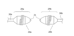
- FIG. 1A and 1B are schematic cross-sectional views of a discharge lamp.
- FIG. 1B is a schematic cross-sectional view enlarging the vicinity of the electrode tip of FIG. 1A.
- the discharge lamp 10 has a substantially spherical light emitting portion 11 formed by a discharge vessel made of quartz glass.
- the material of the discharge vessel is not limited to quartz glass, and may be made of other materials.
- a pair of electrodes 20a and 20b are disposed to face each other at an extremely small interval of, for example, 2 mm or less.
- sealing portions 12 are formed at both ends of the light emitting portion 11.
- a conductive metal foil 13 made of molybdenum or the like is hermetically embedded in the sealing portion 12 by, for example, a shrink seal.
- the shaft portions of the electrodes 20a and 20b are joined to one end of the metal foil 13, and the external lead 14 is joined to the other end of the metal foil 13, and power is supplied from a discharge lamp lighting device to be described later.
- Mercury is used to obtain the necessary visible light wavelength, for example, radiation having a wavelength of 360 to 780 nm, and, in terms of specific values, 0.20 mg / mm 3 or more is enclosed.
- a high vapor pressure of 200 atm or more is realized as the pressure inside the light emitting unit during lighting.
- argon gas is sealed at about 13 kPa. Its function is to improve the lighting startability.
- halogen gas iodine, bromine, chlorine, etc. are enclosed in the form of a compound with mercury or other metals.
- the amount of enclosed halogen is selected from the range of 10 ⁇ 6 ⁇ mol / mm 3 to 10 ⁇ 2 ⁇ mol / mm 3 .
- the biggest reason for enclosing the halogen is to extend the life of the discharge lamp using a so-called halogen cycle.
- the discharge lamp 10 is extremely small and has a very high lighting vapor pressure, the effect of preventing devitrification of the discharge vessel can be obtained by enclosing the halogen.
- Devitrification means that crystallization proceeds from a metastable glass state and changes to an aggregate of crystal grains grown from many crystal nuclei. If such a phenomenon occurs, light is scattered at the grain boundaries of the crystal and the discharge vessel becomes opaque.
- the gas enclosed with the light emission part 11 is not limited to the said gas.
- the maximum outer diameter of the light emitting part is 9.4 mm
- the distance between the electrodes is 1.0 mm
- the inner volume of the discharge vessel is 55 mm 3
- the rated voltage is 70 V
- the rated power is 180 W. It can be set as a structure.
- the discharge lamp 10 when it is assumed that a discharge lamp 10 is built in and used in a projector that has been miniaturized in recent years, the discharge lamp 10 is required to be extremely small as a whole size, and on the other hand, a high light emission amount is also required. . For this reason, the thermal influence in the light emitting portion is extremely severe, and the lamp wall load value of the lamp is 0.8 to 2.5 W / mm 2 , specifically 2.4 W / mm 2 . As described above, the discharge lamp 10 having a high mercury vapor pressure and a tube wall load value is mounted on a presentation device such as a projector or an overhead projector, thereby providing the presentation device with emitted light having good color rendering properties. be able to.
- a presentation device such as a projector or an overhead projector
- the electrode 20a includes a head portion 29a and a shaft portion 30a
- the electrode 20b includes a head portion 29b and a shaft portion 30b.
- Each of the electrode 20a and the electrode 20b has a protrusion 21 at the tip.
- the protrusion 21 is formed by agglomerating molten electrode material at the electrode tip when the lamp is turned on.
- the electrode 20a and the electrode 20b are described as both made of tungsten, but the material is not limited to this.
- the electrode 20a and the electrode 20b are energized, the electrode 20a is heated to a high temperature, and the tungsten constituting them is sublimated.
- the sublimated tungsten is combined with the enclosed halogen gas in the inner wall surface region of the light emitting portion 11 which is a relatively low temperature portion to form tungsten halide. Since the vapor pressure of tungsten halide is relatively high, it moves again in the vicinity of the tips of the electrodes 20a and 20b in the gas state. When heated again at this point, the tungsten halide is separated into halogen and tungsten.
- tungsten returns to the tips of the electrodes 20 a and 20 b and aggregates, and the halogen returns as the halogen gas in the light emitting unit 11. This corresponds to the “halogen cycle” described above.
- the agglomerated tungsten adheres to the vicinity of the tips of the electrode 20a and the electrode 20b, whereby the protrusion 21 is formed.
- FIG. 2 is a circuit block diagram schematically showing the configuration of the discharge lamp lighting device of the present invention.
- the lighting device 1 includes a power supply unit 3, a pulse generation unit 4, and a power control unit 5.
- the pulse generation unit 4 includes a frequency setting unit 41 and a pulse generation circuit 43, and a pulse P having a frequency set by the frequency setting unit 41 is generated by the pulse generation circuit 43 and supplied to the power supply unit 3.
- the power feeding unit 3 generates an alternating current based on a signal (corresponding to the gate signal Gx in FIG. 2) related to the control power value output from the power control unit 5 and the pulse P, and supplies the alternating current to the discharge lamp 10. .
- the discharge lamp 10 lights up when this alternating current is supplied.
- the power feeding unit 3 includes a step-down chopper unit 31, a DC / AC conversion unit 32, and a starter unit 33.
- the step-down chopper unit 31 steps down the supplied direct-current voltage Vdc to a desired direct-current voltage (hereinafter, referred to as “applied voltage” as appropriate), and outputs it to the subsequent DC / AC conversion unit 32.
- the step-down chopper unit 31 includes a switching element Qx, a reactor Lx, a diode Dx, a smoothing capacitor Cx, a resistor Rx, and a voltage dividing resistor (R1, R2). Yes.
- Switching element Qx has one end connected to the + side power supply terminal to which DC voltage Vdc is supplied and the other end connected to one end of reactor Lx.
- the diode Dx has a cathode terminal connected to a connection point between the switching element Qx and the reactor Lx, and an anode terminal connected to the negative side power supply terminal.
- the smoothing capacitor Cx has one end (+ side terminal) connected to the output side terminal of the reactor Lx and the other end ( ⁇ side terminal) connected to the output side terminal of the resistor Rx.
- the resistor Rx is connected between the negative terminal of the smoothing capacitor Cx and the anode terminal of the diode Dx, and realizes a current detection function.
- the voltage dividing resistors (R1, R2) are connected between the negative side terminal and the positive side terminal of the smoothing capacitor Cx to realize a voltage detection function.
- the switching element Qx is driven by a gate signal Gx output from the power control unit 5. Based on the duty of the gate signal Gx, the step-down chopper unit 31 steps down the DC voltage Vdc to a voltage corresponding to the duty and outputs the voltage to the subsequent DC / AC conversion unit 32. That is, the voltage applied to the discharge lamp 10 is determined by the signal from the power control unit 5.
- the DC / AC conversion unit 32 converts the input DC voltage into an AC voltage having a desired frequency and outputs the AC voltage to the subsequent starter unit 33.
- FIG. 2 shows a specific configuration example in which the DC / AC converter 32 is configured by switching elements Q1 to Q4 connected in a bridge shape (full bridge circuit).
- the switching element Q1 is driven by a gate signal G1 output from the driver 35.
- the switching element Q2 is driven by the gate signal G2
- the switching element Q3 is driven by the gate signal G3
- the switching element Q4 is driven by the gate signal G4.
- the driver 35 outputs a gate signal to alternately repeat on / off for the pair of switching elements Q1 and Q4 and the pair of switching elements Q2 and Q3 arranged diagonally. Thereby, a rectangular wave AC voltage is generated between the connection point of the switching elements Q1 and Q2 and the connection point of the switching elements Q3 and Q4.
- the starter unit 33 is a circuit unit for boosting the AC voltage supplied from the DC / AC conversion unit 32 when starting the discharge lamp and supplying the boosted voltage to the discharge lamp 10.
- the starter unit 33 is configured by a coil Lh and a capacitor Ch.
- an AC voltage having a high switching frequency for example, several hundred kHz
- a high switching frequency for example, several hundred kHz
- the frequency of the AC voltage supplied from the DC / AC converter 32 is shifted to a steady frequency (for example, 60 to 1000 Hz), and a steady lighting operation is performed.
- This steady frequency corresponds to the frequency of a pulse P1 described later.
- the change in the frequency of the AC voltage supplied to the starter unit 33 is performed by switching on / off the switching element Q1 and Q4 group and the switching element Q2 and Q3 group in the DC / AC conversion unit 32. This can be achieved by adjusting the period. Further, the change of the peak value of the AC voltage supplied to the starter unit 33 can be achieved by adjusting the operation duty of the switching element Qx in the step-down chopper unit 31.
- the switching element Qx of the step-down chopper unit 31 is turned on / off at a switching frequency corresponding to the duty of the gate signal Gx output from the power control unit 5, thereby changing the power supplied to the discharge lamp 10.
- the power control unit 5 performs control to increase the duty of the gate signal Gx so that a desired power value is obtained.
- the power control unit 5 includes a power calculation unit 51, a comparison unit 53, and a pulse width modulation circuit 55.
- Power calculating unit 51 voltage dividing resistors voltage signal detected by (R1, R2) V L, and a current signal I L that has been detected by the resistor Rx is input, generates a power signal W L based on these signals.
- Comparing unit 53 compares the power value as a reference, a power signal W L which is output from the power calculating unit 51, and outputs the comparison result to the pulse width modulation circuit 55.
- the pulse width modulation circuit 55 changes the duty ratio of the gate signal Gx according to the comparison result from the comparison unit 53.
- the voltage signal V L corresponds to a voltage generated by dividing the DC voltage (that is, the applied voltage) stepped down by the step-down chopper unit 31 by the voltage dividing resistors (R1, R2), and depends on the lamp voltage. Voltage.
- the current signal IL is also a current corresponding to the lamp current. Therefore, the power control unit 5 has a function of performing feedback control so that the applied power is constant, that is, power consumption in the discharge lamp 10 is constant.
- the pulse generation unit 4 includes the frequency setting unit 41 and the pulse generation circuit 43.
- the pulse generation circuit 43 generates a pulse P having a frequency set by the frequency setting unit 41 and outputs the pulse P to the driver 35 of the DC / AC conversion unit 32.
- switching control is performed on the switching elements Q1 to Q4 of the DC / AC conversion unit 32.
- the frequency setting unit 41 can be configured by, for example, a microcomputer.
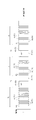
- FIGS. 3A to 3C are diagrams showing examples of the waveform of the pulse P output from the pulse generator 4, that is, the lamp current waveform of the discharge lamp 10.
- FIG. 3A to 3C correspond to the waveforms of the pulses P in different time zones, respectively.
- the pulse P generated from the pulse generator 4 outputs a pulse P1 (corresponding to the “first pulse”) having a fundamental frequency f1 (pulse width W1) for a predetermined period T1, and then a frequency f2 (lower than the fundamental frequency f2).
- a cycle of outputting a pulse P2 (corresponding to “second pulse”) having a pulse width W2) for a predetermined period T2 is repeated.
- the frequency f2 of the second pulse P2 is different, that is, the pulse width W2 and the output period T2 are also different.
- the frequency setting unit 41 may employ a configuration including a memory that stores the number of continuous pulses of the first pulse P1, the number of continuous pulses of the second pulse P2, and the frequency f1 of the first pulse P1. Further, as will be described later, the frequency setting unit 41 sets the frequency f2 of the second pulse P2 according to the value of the applied voltage.
- the pulse generation circuit 43 includes a counter that counts the number of pulses P output from the pulse generation circuit 43, and information on this counter can be sent to the frequency setting unit 41.
- the frequency setting unit 41 switches the first pulse P1 to the second pulse P2 and the second pulse P2 to the second pulse P2 based on the information on the number of pulses given from the counter and the information stored in the memory.
- the timing of switching to one pulse P1 is recognized, and information on each frequency (f1, f2) can be output to the pulse generation circuit 43 in accordance with each timing.
- information on the pulse width W1 of the first pulse P1 and the pulse width W2 of the second pulse P2 may be used instead of the information on the frequency f1 of the first pulse P1 and the frequency f2 of the second pulse P2. I do not care.
- the frequency f1 (fundamental frequency) of the first pulse P1 corresponds to the fundamental frequency when the discharge lamp 10 is steadily lit and is, for example, one frequency selected from the range of 60 to 1000 Hz.
- the second pulse P2 is a low frequency inserted after a predetermined number of first pulses P1 are continuously output, and the frequency f2 is lower than the fundamental frequency, for example, from a range of 5 to 200 Hz. The selected frequency.
- the second pulse P2 is preferably inserted at a time interval of 0.01 seconds to 120 seconds.
- the pulse P2 is inserted at a time interval shorter than 0.01 seconds, the projection 21 serving as the starting point of the arc is excessively heated, and the shape thereof may be deformed or possibly disappear.
- the time interval is too wide, the state in which the minute protrusions are formed at the peripheral position of the protrusion 21 is maintained for a long time, and an arc starting from the minute protrusion may be formed during this time. is there.
- the period T2 during which the second pulse P2 is output is set to one period of the pulse P2. That is, in this period T2, the pulse generation circuit 43 is configured to output positive and negative pulses once each.
- the output form of the pulse P2 is not limited to such a form.
- the pulse generation circuit 43 outputs the first pulse P1 only for a predetermined period T1
- the second pulse P2 is output only for the half cycle length T2
- the first pulse P1 is output only for the time T1
- the second pulse P2 Alternatively, a configuration may be adopted in which the polarity is changed as before and only the half cycle length T2 is output.
- the second pulse P2 included in the pulse P output from the pulse generation circuit 43 may be included over a period of one cycle or more, such as 1.5 cycles of the second pulse P2.
- the electrode may be heated too much and the shape of the protrusion 21 serving as the arc starting point may change, so the second pulse P2 is applied for one cycle within one cycle. It is preferable to keep within.
- the frequency setting unit 41 sets the frequency f2 of the second pulse P2 according to the value of the applied voltage. Specifically, when the applied voltage matches a predetermined reference value, the frequency f2 of the second pulse P2 is set to a predetermined reference frequency. And when the value of an applied voltage exceeds this reference value, the frequency f2 of the 2nd pulse P2 is set to a frequency lower than a reference frequency. On the other hand, when the value of the applied voltage is lower than the reference value, the frequency f2 of the second pulse P2 is set to a frequency equal to or lower than the reference frequency.
- the frequency setting unit 41 is supplied with the voltage signal V L from the power supply unit 3 (see FIG. 2).
- the voltage signal V L corresponds to a voltage generated by dividing the DC voltage stepped down by the step-down chopper unit 31 by the voltage dividing resistors (R1, R2). According to the voltage. Therefore, the frequency setting unit 41 can detect the applied voltage based on the voltage signal VL .
- the frequency setting unit 41 may store the relationship between the applied voltage and the frequency f2 of the second pulse P2 in the form of a data table, or may store it in a predetermined relational expression.
- the frequency setting unit 41 uses the second pulse so that the frequency decreases as the value of the applied voltage increases from the reference value both when the applied voltage exceeds the reference value and when the applied voltage falls below the reference value.
- the frequency f2 of P2 is set will be described. In this case, when the applied voltage matches the reference value, the frequency f2 of the second pulse P2 indicates the highest frequency (corresponding to the “reference frequency”).
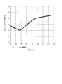
- FIG. 4 is an example of a graph showing the relationship between the applied voltage and the second pulse P2.
- the relationship between the applied voltage and the pulse width W2 of the second pulse P2 is shown.
- the example of FIG. 4 shows that when the applied voltage is 68 V, which is the reference value, the pulse width W2 of the second pulse P2 is the shortest and the frequency f2 at this time is the highest. Yes.
- the numerical values shown in FIG. 4 are merely examples.
- FIG. 3B corresponds to an example of the waveform of the pulse P when the applied voltage is 68V, for example.
- 3C corresponds to an example of the waveform of the pulse P when the applied voltage is 90 V, for example.
- FIG. 3A corresponds to an example of the waveform of the pulse P when the applied voltage is 55 V, for example.
- the pulse width W2 of the second pulse P2 is the shortest, and the frequency f2 of the second pulse P2 is the highest.
- the frequency f2 of the second pulse P2 shown in FIG. 3A is lower than the frequency f2 of the second pulse P2 shown in FIG. 3B.
- the frequency f2 of the second pulse P2 shown in FIG. 3C is lower than the frequency f2 of the second pulse P2 shown in FIG. 3A.
- the reference value is set to 68 V.
- the design of the electrodes (20a, 20b), the internal volume of the light emitting unit 11 (discharge vessel), the amount of enclosed mercury, and the like of the discharge lamp 10 itself is a value set as appropriate according to the design.
- Example 1 The case where the discharge lamp 10 was turned on by the discharge lamp lighting device 1 described above was taken as Example 1.
- the frequency of the first pulse P1 was 370 Hz (pulse width was about 1.4 ms).
- the specifications of the discharge lamp 10 are as follows.
- FIG. 5A is a graph showing the relationship between the applied voltage and the second pulse P2 in the case of Comparative Example 1 following FIG.
- Comparative Example 2 When the applied voltage is increased, the frequency f2 of the second pulse P2 is decreased (the pulse width W2 is increased), and when the applied voltage is decreased, the frequency f2 of the second pulse P2 is increased (the pulse width W2 is decreased).
- the case where the frequency f2 of the second pulse P2 was adjusted was referred to as Comparative Example 2.
- This comparative example 2 assumes the lighting method disclosed in Patent Document 2. The other points are common to the first embodiment.
- FIG. 5B is a graph showing the relationship between the applied voltage and the second pulse P2 in the case of Comparative Example 2 following FIG.
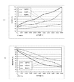
- FIG. 6 is a graph comparing changes over time in applied voltage and illuminance maintenance ratio when the discharge lamp is turned on in each lighting device in each of Example 1, Comparative Example 1, and Comparative Example 2.
- 6A is a graph showing the relationship between the applied voltage and the elapsed time
- FIG. 6B is a graph showing the relationship between the illuminance maintenance rate and the elapsed time.
- the “illuminance maintenance rate” is a value indicating the ratio of the brightness at each time point when the brightness immediately after lighting is set as a reference (100%).
- Comparative Example 1 is about 400 hours and Comparative Example 2 is about 2000 hours, whereas Example 1 is about 5000 hours.
- the applied voltage after 5000 hours from the start of lighting was 150 V in Comparative Example 1 and 130 V in Comparative Example 2, whereas Example 1 remained at 80 V.
- Comparative Example 1 has the fastest applied voltage increase rate, and Comparative Example 2 has a lower applied voltage increase rate than Comparative Example 1. This confirms the effect of reducing the frequency f2 of the second pulse P2 as the applied voltage increases.
- Comparative Example 1 is about 1500 hours and Comparative Example 2 is about 2300 hours, whereas Example 1 is About 3500 hours.
- the illuminance maintenance rate after 5000 hours from the start of lighting was about 23% in Comparative Example 1 and about 27% in Comparative Example 2, whereas it was 50% in Example 1.
- Comparative Example 1 has the fastest decrease rate of the illuminance maintenance rate
- Comparative Example 2 has a lower decrease rate than Comparative Example 1.
- the illumination maintenance rate tends to decrease as the distance between the electrodes becomes longer compared to the time of the initial lighting, and the comparison that can suppress the speed at which the distance between the electrodes becomes longer is suppressed. It can be seen that Example 2 can suppress the rate of decrease in the illuminance maintenance rate more than Comparative Example 1.
- Example 1 the increase in applied voltage and the decrease in the illuminance maintenance rate in Example 1 can be largely suppressed as compared with both Comparative Example 1 and Comparative Example 2. That is, according to the discharge lamp lighting device 1 described above, it is suggested that the life of the discharge lamp can be further extended, particularly compared with the method of Comparative Example 2.
- FIG. 6 (a) it can be seen that the applied voltage is lower in Example 1 than in Comparative Example 1 and Comparative Example 2 in the initial lighting stage until about 200 hours have elapsed since the start of lighting.
- FIG. 6B in this initial lighting stage, unlike Example 1 and Comparative Example 2, in Example 1, the illuminance maintenance rate is higher than immediately after lighting.
- the pulse width W2 of the second pulse P2 is increased to further reduce the frequency f2. In the initial stage of lighting, the electrode material is abundant.
- the distance between the electrodes can be shortened in the initial stage, and the time during which the discharge lamp 10 can be lit with a low applied voltage can be lengthened. Can be made longer. In addition, since the speed at which the distance between the electrodes becomes longer can be suppressed, the life of the discharge lamp can be extended as compared with the conventional case.
- the pulse width W2 of the second pulse P2 is the shortest when the applied voltage is the reference value (the frequency f2 is the highest), and the pulse width W2 becomes longer as the applied voltage falls below the reference value. This is explained assuming that the frequency f2 becomes lower (see FIG. 4). However, when the applied voltage is below the reference value, the pulse width W2 of the second pulse P2 may be equal to the pulse width W2 at the reference value.
- FIG. 7 is an example of a graph showing the relationship between the applied voltage and the second pulse P2 at this time.
- the discharge lamp 10 is assumed to be subjected to constant power control.
- eco mode a lighting method that switches the lighting power value itself, for example, when the projector apparatus is used with reduced brightness on the screen.
- normal mode a lighting method that switches the lighting power value itself
- the lighting power in normal time hereinafter referred to as “normal mode”
- the lighting power in the eco mode is 120 W.
- the frequency setting unit 41 is configured to receive a power signal W L from the power calculating unit 51, according to the value of the power signal W L, the frequency f2 of the second pulse P2 (pulse The width W2) may be changed.
- the pulse width W2 of the second pulse P2 may be used to set the ratio corresponding to the rate of change of the power signal W L.
- the pulse generation unit 4 has been described as repeating the cycle of outputting the first pulse P1 for a predetermined time and then outputting the second pulse P2 for a predetermined period.
- the pulse generator 4 outputs a lower-frequency third pulse instead of the second pulse P2, and then returns to the cycle in which the first pulse P1 and the second pulse P2 are output again. It doesn't matter.
- the third pulse is exceptionally output instead of the second pulse P2 only once every several tens to several hundreds of cycles for the purpose of eliminating the moved protrusion.
- SYMBOLS 1 Discharge lamp lighting device 3: Power supply part 4: Pulse generation part 5: Power control part 10: Discharge lamp 11: Light emission part 12: Sealing part 13: Metal foil 14: External lead 20a, 20b: Electrode 21: Protrusion 29a 29b: Electrode head 30a, 30b: Electrode shaft 31: Step-down chopper 32: DC / AC converter 33: Starter 35: Driver 41: Frequency setting unit 43: Pulse generation circuit 51: Power calculation unit 53 : Comparison unit 55: Pulse width modulation circuit
Abstract
La présente invention se rapporte à un procédé d'éclairage, qui permet de prolonger la durée de vie d'une lampe à décharge par rapport à un cas dans lequel l'éclairage est effectué selon une manière d'éclairage classique. Un appareil d'éclairage à lampe à décharge comprend une unité de génération d'impulsions et une unité d'alimentation en énergie pour transformer une tension continue fournie en une tension d'application de courant continu (CC) et convertir la tension d'application en courant alternatif (CA) selon une fréquence d'une impulsion pour fournir ainsi le courant alternatif à la lampe à décharge. L'unité de génération d'impulsions a une configuration qui peut transmettre alternativement une première impulsion et une seconde impulsion présentant une fréquence inférieure à celle de la première impulsion. Lorsqu'une valeur de tension d'application correspond à une valeur de référence prédéterminée, la fréquence de la seconde impulsion est définie comme étant une fréquence de référence prédéterminée. Lorsque la valeur de tension d'application dépasse la valeur de référence, la fréquence de la seconde impulsion est établie de sorte à être inférieure à la fréquence de référence et, lorsque la valeur de tension d'application est inférieure à la valeur de référence, la fréquence de la seconde impulsion est établie de sorte à être égale ou inférieure à la fréquence de référence.
Priority Applications (1)
| Application Number | Priority Date | Filing Date | Title |
|---|---|---|---|
| US15/323,572 US9730304B2 (en) | 2014-07-10 | 2015-06-29 | Discharge lamp lighting apparatus |
Applications Claiming Priority (2)
| Application Number | Priority Date | Filing Date | Title |
|---|---|---|---|
| JP2014-142722 | 2014-07-10 | ||
| JP2014142722A JP5895977B2 (ja) | 2014-07-10 | 2014-07-10 | 放電ランプ点灯装置 |
Publications (1)
| Publication Number | Publication Date |
|---|---|
| WO2016006485A1 true WO2016006485A1 (fr) | 2016-01-14 |
Family
ID=55064122
Family Applications (1)
| Application Number | Title | Priority Date | Filing Date |
|---|---|---|---|
| PCT/JP2015/068615 WO2016006485A1 (fr) | 2014-07-10 | 2015-06-29 | Appareil d'éclairage à lampe à décharge |
Country Status (3)
| Country | Link |
|---|---|
| US (1) | US9730304B2 (fr) |
| JP (1) | JP5895977B2 (fr) |
| WO (1) | WO2016006485A1 (fr) |
Families Citing this family (7)
| Publication number | Priority date | Publication date | Assignee | Title |
|---|---|---|---|---|
| JP6548039B2 (ja) * | 2016-09-01 | 2019-07-24 | ウシオ電機株式会社 | 放電ランプ点灯装置 |
| JP6972825B2 (ja) | 2017-09-20 | 2021-11-24 | セイコーエプソン株式会社 | 放電灯駆動装置、光源装置、プロジェクター、および放電灯駆動方法 |
| JP6981131B2 (ja) | 2017-09-20 | 2021-12-15 | セイコーエプソン株式会社 | 放電灯駆動装置、光源装置、プロジェクター、および放電灯駆動方法 |
| JP6981132B2 (ja) | 2017-09-20 | 2021-12-15 | セイコーエプソン株式会社 | 放電灯駆動装置、光源装置、プロジェクター、および放電灯駆動方法 |
| JP6907864B2 (ja) | 2017-09-29 | 2021-07-21 | セイコーエプソン株式会社 | 放電灯駆動装置、光源装置、プロジェクター、および放電灯駆動方法 |
| JP6939524B2 (ja) | 2017-12-25 | 2021-09-22 | セイコーエプソン株式会社 | 放電灯駆動装置、光源装置、プロジェクター、および放電灯駆動方法 |
| JP6939523B2 (ja) * | 2017-12-25 | 2021-09-22 | セイコーエプソン株式会社 | 放電灯駆動装置、光源装置、プロジェクター、および放電灯駆動方法 |
Citations (3)
| Publication number | Priority date | Publication date | Assignee | Title |
|---|---|---|---|---|
| JP2003133091A (ja) * | 2001-10-26 | 2003-05-09 | Matsushita Electric Ind Co Ltd | 高圧放電ランプの点灯方法、点灯装置及び高圧放電ランプ装置 |
| JP2009252352A (ja) * | 2008-04-01 | 2009-10-29 | Panasonic Corp | 高圧放電ランプ点灯装置、それを用いた高圧放電ランプ装置、その高圧放電ランプ装置を用いたプロジェクタ、および高圧放電ランプの点灯方法 |
| JP2010140732A (ja) * | 2008-12-11 | 2010-06-24 | Ushio Inc | 高圧放電ランプ点灯装置 |
Family Cites Families (4)
| Publication number | Priority date | Publication date | Assignee | Title |
|---|---|---|---|---|
| JP4416125B2 (ja) | 2004-03-18 | 2010-02-17 | ウシオ電機株式会社 | 高圧放電ランプ点灯装置 |
| US7023144B2 (en) | 2004-03-18 | 2006-04-04 | Ushiodenki Kabushiki Kaisha | Device for operation of a high pressure discharge lamp |
| WO2011122274A1 (fr) * | 2010-03-30 | 2011-10-06 | ウシオ電機株式会社 | Dispositif d'éclairage à lampe à décharge haute pression |
| JP5158242B2 (ja) | 2011-08-01 | 2013-03-06 | ウシオ電機株式会社 | 高圧放電ランプ点灯装置 |
-
2014
- 2014-07-10 JP JP2014142722A patent/JP5895977B2/ja not_active Expired - Fee Related
-
2015
- 2015-06-29 WO PCT/JP2015/068615 patent/WO2016006485A1/fr active Application Filing
- 2015-06-29 US US15/323,572 patent/US9730304B2/en not_active Expired - Fee Related
Patent Citations (3)
| Publication number | Priority date | Publication date | Assignee | Title |
|---|---|---|---|---|
| JP2003133091A (ja) * | 2001-10-26 | 2003-05-09 | Matsushita Electric Ind Co Ltd | 高圧放電ランプの点灯方法、点灯装置及び高圧放電ランプ装置 |
| JP2009252352A (ja) * | 2008-04-01 | 2009-10-29 | Panasonic Corp | 高圧放電ランプ点灯装置、それを用いた高圧放電ランプ装置、その高圧放電ランプ装置を用いたプロジェクタ、および高圧放電ランプの点灯方法 |
| JP2010140732A (ja) * | 2008-12-11 | 2010-06-24 | Ushio Inc | 高圧放電ランプ点灯装置 |
Also Published As
| Publication number | Publication date |
|---|---|
| US20170142816A1 (en) | 2017-05-18 |
| US9730304B2 (en) | 2017-08-08 |
| JP2016018746A (ja) | 2016-02-01 |
| JP5895977B2 (ja) | 2016-03-30 |
Similar Documents
| Publication | Publication Date | Title |
|---|---|---|
| JP5895977B2 (ja) | 放電ランプ点灯装置 | |
| US9030111B2 (en) | High pressure discharge lamp lighting device with electrode temperature control | |
| CN101742790B (zh) | 高压放电灯点灯装置 | |
| JP4985690B2 (ja) | 高圧放電ランプ点灯装置 | |
| JP2004296427A (ja) | 超高圧水銀ランプ発光装置 | |
| JP5158242B2 (ja) | 高圧放電ランプ点灯装置 | |
| CN101861037A (zh) | 高压放电灯点灯装置 | |
| JP5896152B2 (ja) | 高圧放電ランプ点灯装置 | |
| JP5625438B2 (ja) | 高圧放電ランプ点灯装置 | |
| JP4389623B2 (ja) | 高圧放電ランプ点灯装置 | |
| CN1717142B (zh) | 高压放电灯照明装置 | |
| JP5565711B1 (ja) | 高圧放電ランプ点灯装置及びこれを備えた画像形成装置 | |
| JP6278255B2 (ja) | 放電ランプ点灯装置 | |
| JP4883292B2 (ja) | 高圧放電灯点灯装置及び高圧放電灯の調光方法 | |
| JP6548039B2 (ja) | 放電ランプ点灯装置 | |
| WO2015093117A1 (fr) | Appareil d'éclairage de lampe à décharge | |
| JP5692325B2 (ja) | 高圧放電ランプ点灯装置 | |
| JP2018037339A (ja) | 放電ランプ点灯装置 |
Legal Events
| Date | Code | Title | Description |
|---|---|---|---|
| 121 | Ep: the epo has been informed by wipo that ep was designated in this application |
Ref document number: 15819243 Country of ref document: EP Kind code of ref document: A1 |
|
| WWE | Wipo information: entry into national phase |
Ref document number: 15323572 Country of ref document: US |
|
| NENP | Non-entry into the national phase |
Ref country code: DE |
|
| 122 | Ep: pct application non-entry in european phase |
Ref document number: 15819243 Country of ref document: EP Kind code of ref document: A1 |