WO2016006469A1 - プレスフィット端子および基板用コネクタ - Google Patents
プレスフィット端子および基板用コネクタ Download PDFInfo
- Publication number
- WO2016006469A1 WO2016006469A1 PCT/JP2015/068389 JP2015068389W WO2016006469A1 WO 2016006469 A1 WO2016006469 A1 WO 2016006469A1 JP 2015068389 W JP2015068389 W JP 2015068389W WO 2016006469 A1 WO2016006469 A1 WO 2016006469A1
- Authority
- WO
- WIPO (PCT)
- Prior art keywords
- press
- fit
- terminal
- fitting
- fit terminal
- Prior art date
Links
Images


Classifications
-
- C—CHEMISTRY; METALLURGY
- C25—ELECTROLYTIC OR ELECTROPHORETIC PROCESSES; APPARATUS THEREFOR
- C25D—PROCESSES FOR THE ELECTROLYTIC OR ELECTROPHORETIC PRODUCTION OF COATINGS; ELECTROFORMING; APPARATUS THEREFOR
- C25D5/00—Electroplating characterised by the process; Pretreatment or after-treatment of workpieces
- C25D5/10—Electroplating with more than one layer of the same or of different metals
-
- C—CHEMISTRY; METALLURGY
- C25—ELECTROLYTIC OR ELECTROPHORETIC PROCESSES; APPARATUS THEREFOR
- C25D—PROCESSES FOR THE ELECTROLYTIC OR ELECTROPHORETIC PRODUCTION OF COATINGS; ELECTROFORMING; APPARATUS THEREFOR
- C25D5/00—Electroplating characterised by the process; Pretreatment or after-treatment of workpieces
- C25D5/48—After-treatment of electroplated surfaces
- C25D5/50—After-treatment of electroplated surfaces by heat-treatment
-
- C—CHEMISTRY; METALLURGY
- C25—ELECTROLYTIC OR ELECTROPHORETIC PROCESSES; APPARATUS THEREFOR
- C25D—PROCESSES FOR THE ELECTROLYTIC OR ELECTROPHORETIC PRODUCTION OF COATINGS; ELECTROFORMING; APPARATUS THEREFOR
- C25D7/00—Electroplating characterised by the article coated
-
- H—ELECTRICITY
- H01—ELECTRIC ELEMENTS
- H01R—ELECTRICALLY-CONDUCTIVE CONNECTIONS; STRUCTURAL ASSOCIATIONS OF A PLURALITY OF MUTUALLY-INSULATED ELECTRICAL CONNECTING ELEMENTS; COUPLING DEVICES; CURRENT COLLECTORS
- H01R12/00—Structural associations of a plurality of mutually-insulated electrical connecting elements, specially adapted for printed circuits, e.g. printed circuit boards [PCB], flat or ribbon cables, or like generally planar structures, e.g. terminal strips, terminal blocks; Coupling devices specially adapted for printed circuits, flat or ribbon cables, or like generally planar structures; Terminals specially adapted for contact with, or insertion into, printed circuits, flat or ribbon cables, or like generally planar structures
- H01R12/50—Fixed connections
- H01R12/51—Fixed connections for rigid printed circuits or like structures
- H01R12/55—Fixed connections for rigid printed circuits or like structures characterised by the terminals
- H01R12/58—Fixed connections for rigid printed circuits or like structures characterised by the terminals terminals for insertion into holes
-
- H—ELECTRICITY
- H01—ELECTRIC ELEMENTS
- H01R—ELECTRICALLY-CONDUCTIVE CONNECTIONS; STRUCTURAL ASSOCIATIONS OF A PLURALITY OF MUTUALLY-INSULATED ELECTRICAL CONNECTING ELEMENTS; COUPLING DEVICES; CURRENT COLLECTORS
- H01R13/00—Details of coupling devices of the kinds covered by groups H01R12/70 or H01R24/00 - H01R33/00
- H01R13/02—Contact members
- H01R13/03—Contact members characterised by the material, e.g. plating, or coating materials
Definitions
- a press-fit terminal is known as a terminal that is press-fitted into a through hole of a circuit board (for example, see Patent Document 1).
- the press-fit terminal is a terminal that is electrically connected by elastic contact with a conductive portion formed on the inner periphery of the through hole of the circuit board.
- Sn plating is applied to the surface of a metal substrate made of copper or a copper alloy.
- Sn has a lower hardness than other metals. Therefore, even when Sn is oxidized to form an insulating film, this film is broken with a relatively weak force. Therefore, a press-fit terminal having Sn plating on the surface of a metal base material is relatively easy to break when mated with the mating terminal and the new surface is exposed, thereby ensuring a good electrical connection. Can do.
- the present invention has been made in view of the above-mentioned background, and without applying different plating to the outermost surfaces of the fitting portion and the press-fit portion, lowering the fitting force on the fitting portion side and plating scraping on the press-fit portion side. It is an object of the present invention to provide a press-fit terminal capable of suppressing the above and a board connector using the same.
- One aspect of the present invention is a fitting portion that is electrically connected by fitting with a counterpart terminal, and a conductive portion formed on the inner periphery of the through hole by being press-fitted into the through hole of the circuit board.
- the fitting part and the press-fit part both have an alloy plating layer composed of a mixed phase of an Sn—Pd-based alloy phase and an Sn phase on the outermost surface. It is in.
- Another aspect of the present invention is a board connector including the press-fit terminal and a housing that holds the press-fit terminal.
- the fitting part and the press-fit part both have an alloy plating layer composed of a mixed phase of Sn—Pd alloy phase and Sn phase on the outermost surface.
- the Sn—Pd alloy phase is relatively hard as compared with the Sn phase. Therefore, the surface of the alloy plating layer is smaller than that of the conventional Sn plating layer. Therefore, the press-fit terminal has a reduced fitting force when mated with the counterpart terminal. Further, the alloy plating layer has reduced wear due to Sn adhesion and digging found in conventional Sn plating layers.
- the press-fit terminal has a low fit on the fitting portion side by having one type of the alloy plating layer on the outermost surface without performing different plating on the outermost surfaces of the fitting portion and the press-fit portion. The resultant force is achieved, and plating scraping is suppressed on the press fit portion side.
- the board connector uses the press-fit terminal. Therefore, the fitting force with the mating board connector having the mating terminal can be reduced. Further, since plating scraping from the press-fit portion hardly occurs during mounting on the circuit board, the connection reliability of the circuit board can be improved.
- the entire outermost surface may be covered with the alloy plating layer, or a part of the outermost surface not covered with the alloy plating layer There may be.
- the latter include, for example, a punched fracture surface when a press-fit terminal is formed by stamping a plate-shaped terminal material and then pressing it.
- the press-fit terminal may have a connection part that connects the fitting part and the press-fit part.
- a connection part can be set as the structure which has the said alloy plating layer in the outermost surface.
- the base metal for example, Cu or Cu alloy, Al or Al alloy, or the like can be used as the base metal that forms the terminal shape.
- the metal substrate Cu or a Cu alloy can be suitably used from the viewpoint of high conductivity, excellent workability, and appropriate strength.
- the Sn—Pd alloy phase in the alloy plating layer has a high effect in reducing the friction coefficient.
- the area ratio is preferably 10% or more, more preferably 20% or more, and further Preferably, it can be 30% or more.
- the Sn phase in the alloy plating layer has a high effect on reducing the contact resistance.
- the area ratio is preferably 80% or less, more preferably 70% or less, and even more preferably 60% or less.
- the Pd content is preferably less than 20 atomic%, more preferably 15 atomic% or less, still more preferably 10 atomic% or less, and even more preferably, from the viewpoint of easily ensuring the stability of contact resistance. , 7 atomic% or less.
- the Pd content is preferably 1 atomic% or more, more preferably 2 atomic% or more, from the viewpoint of promoting stable production of an intermetallic compound such as PdSn 4 that contributes to reduction of the friction coefficient. More preferably, it is 3 atomic% or more, More preferably, it can be 4 atomic% or more.
- the thickness of the alloy plating layer can be set to 0.8 ⁇ m or more, preferably about 0.8 to 2 ⁇ m from the viewpoint of wear resistance, heat resistance, and the like.
- the board connector includes the press-fit terminal and a housing that holds the press-fit terminal.
- the press-fit terminal may be configured to be held in the housing by being press-fitted into the back wall of the synthetic resin housing, for example.
- a connecting portion that connects between the fitting portion and the press-fit portion may be formed in a shape such as an “L” shape.
- the board connector may be configured such that a plurality of the press-fit terminals are held in a housing.
- each press-fit terminal has a low fitting force, it is possible to effectively reduce the fitting force that increases as the number of terminals increases. Therefore, in this case, the mating board connector can be fitted with a low fitting force.
- the press-fit terminal 1 is applied to a board connector 2 mounted on an automobile.
- the press-fit terminal 1 has a connecting portion 13 that connects between the fitting portion 11 and the press-fit portion 12.
- a press-fit portion 12 is formed by pressing, and the fitting portion 11 is inserted into the terminal press-fitting hole 211 provided in the housing 21 of the board connector 2. After being press-fitted from the side, it is formed by being bent into an “L” shape.
- the fitting portion 11 is specifically formed in a tab shape, and is inserted into a cylindrical counterpart fitting portion of the counterpart terminal.
- the connecting portion 13 is formed in an “L” shape, and a pair of retaining portions 131 and a pair of positioning portions 132 are stuck in the width direction at the end portion on the fitting portion 11 side. It is formed with.
- the retaining part 131 the edge near the front-end
- the press fit terminal 1 can be press-fitted into the terminal press-fitting hole 211 from the fitting portion 11 side.
- the edge on the opposite side to the front end side of the retaining portion 131 is raised, the retaining portion 131 is prevented from being detached when press-fitted.
- the positioning portion 132 has a sharp edge near the tip, the positioning portion 132 is locked to the edge of the terminal press-fitting hole 211 when press-fitted. Thereby, the press fit terminal 1 can be positioned.
- a pair of jig abutting parts 123 for contacting a press-fitting jig (not shown) when press-fitting the press-fit part 12 into the through hole 31 are provided in the width direction on the base end side of the press-fit part 12. It is formed in an overhanging state.
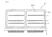
- the board connector 2 of this example includes a press-fit terminal 1 and a housing 21 that holds the press-fit terminal 1.
- the board connector 2 has a plurality of press-fit terminals 1 assembled to the housing 21.
- the housing 21 is made of a synthetic resin, and a hood portion 213 that accommodates a mating board connector (not shown) is formed on the front side of the housing 21 when fitted, and a back wall 212 is integrally formed behind the hood portion 213. ing.
- the press-fit terminal 1 is held in the housing 21 by being press-fitted from the fitting portion 11 side into a terminal press-fitting hole 211 formed in the back wall 212 of the housing 21.
- the fitting portion 11 and the press-fit portion 12 both have an alloy plating layer 14 composed of a mixed phase of the Sn—Pd alloy phase 141 and the Sn phase 142 on the outermost surface.
- the alloy plating layer 14 is relatively hard as compared with the Sn phase 142. Therefore, the alloy plating layer 14 has a smaller surface friction coefficient than the conventional Sn plating layer. Therefore, the press-fit terminal 1 has a reduced fitting force when mated with the counterpart terminal. Further, the alloy plating layer 14 is reduced in wear due to Sn adhesion and digging found in the conventional Sn plating layer.
- the press-fit terminal 1 is less likely to cause excessive Sn adhesion or digging, and it is difficult to cause Sn scraping.
- the press-fit terminal 1 has one type of alloy plating layer 14 on the outermost surface without applying different plating to the outermost surfaces of the fitting portion 11 and the press-fit portion 12, thereby allowing the fitting portion 11 side. In this case, a low fitting force is achieved, and plating scraping is suppressed on the press fit portion 12 side.
- the press-fit terminal 1 of this example is used for the board connector 2 of this example. Therefore, the fitting force with the mating board connector having the mating terminal can be reduced. In addition, since plating scraping from the press-fit portion 12 hardly occurs during mounting on the circuit board 3, the connection reliability of the circuit board 3 can be improved.
- a 1 ⁇ m thick Ni plating layer, a 20 nm thick Pd plating layer, and a 1 ⁇ m thick Sn plating layer are sequentially formed on the surface of a plate-shaped metal substrate (thickness 0.64 ⁇ m) made of a Cu alloy by electroplating.
- a terminal material was obtained by heat treatment in the atmosphere at a temperature equal to or higher than the melting point of Sn.
- the obtained terminal material was punched into a terminal development shape that can be made into the terminal shape shown in FIGS. 1 and 2 by press working, and then a press fit portion was formed by press working.
- the punched piece formed with the press-fit portion is press-fitted into the terminal press-fitting hole of the housing made of PBT resin, and then bent into an “L” shape to form a bent portion.
- a substrate connector of Sample 1C was obtained.
- the press fit terminal of this example is a 0.64 type.
- the board connector is a multipolar connector in which a plurality of press-fit terminals are arranged as shown in FIGS.
- each of the fitting part, the press-fit part, and the connecting part includes a plate-like metal base material made of a Cu alloy, a Ni layer in contact with the metal base material (thickness 1 ⁇ m), and Ni in contact with the Ni layer. It was confirmed that it had an —Sn layer and an alloy plating layer (thickness 1 ⁇ m) composed of a mixed phase of an Sn—Pd alloy phase and an Sn phase in contact with the Ni—Sn layer.
- FIG. 6 shows the relationship between the mating distance and the mating force when the board connectors of Sample 1C and Sample 2C are mated with the mating board connector.
- the board connector of the sample 1C has a smaller fitting force than the board connector of the sample 2C. This is because the friction coefficient on the surface of the fitting portion is reduced by having the alloy plating layer on the outermost surface of the fitting portion.
- press fitting that can reduce the fitting force on the fitting portion side and suppress plating scraping on the press fit portion side without applying different plating to the outermost surfaces of the fitting portion and the press fit portion. It was confirmed that a terminal and a board connector using the terminal were obtained.
- the press-fit terminal may be directly mounted on the circuit board without being held by the housing of the board connector.
Landscapes
- Chemical & Material Sciences (AREA)
- Engineering & Computer Science (AREA)
- Chemical Kinetics & Catalysis (AREA)
- Electrochemistry (AREA)
- Materials Engineering (AREA)
- Metallurgy (AREA)
- Organic Chemistry (AREA)
- Coupling Device And Connection With Printed Circuit (AREA)
- Electroplating Methods And Accessories (AREA)
Abstract
プレスフィット端子(1)は、相手方端子と嵌合することにより電気的接続が取られる嵌合部(11)と、回路基板(3)のスルーホール(31)内に圧入されることによりスルーホール(31)の内周に形成された導電部(32)と電気的接続が取られるプレスフィット部(12)とを有している。嵌合部(11)およびプレスフィット部(12)は、いずれも、Sn-Pd系合金相(141)とSn相(142)との混合相より構成される合金めっき層(14)を最表面に有している。
Description
本発明は、プレスフィット端子および基板用コネクタに関する。
従来、回路基板のスルーホール内に圧入される端子として、プレスフィット端子が知られている(例えば、特許文献1参照)。プレスフィット端子は、回路基板のスルーホール内周に形成された導電部と弾性接触させることにより電気的接続が取られる端子である。
プレスフィット端子を構成するための金属基材として、導電率が高く、延性に富み、適度な強度を有する銅や銅合金が多く使用されている。銅や銅合金は、表面に酸化膜や硫化膜等の絶縁性の被膜が形成される。そのため、銅や銅合金をそのまま用いたプレスフィット端子は、相手方端子との嵌合時に接触抵抗が高くなりやすい。
そこで、従来より、銅や銅合金からなる金属基材の表面には、Snめっきが施されている。Snは、他の金属と比較して硬度が低い。そのため、Snが酸化されて絶縁性の被膜が形成された場合でも、この被膜は、比較的弱い力で破壊される。それ故、金属基材の表面にSnめっきを有するプレスフィット端子は、相手方端子との嵌合時に比較的容易に被膜が破壊されて新生面が露出し、これにより良好な電気的接続を確保することができる。
しかしながら、従来技術は、以下の点で問題がある。すなわち、上述したように、Snは、比較的軟らかい金属である。そのため、相手方端子とプレスフィット端子との嵌合時に、相手方端子と嵌合部との間で、Snの凝着や掘り起こしが生じ、嵌合力が過大になりやすいという問題がある。
また、プレスフィット端子を備える基板用コネクタを回路基板に実装する際、回路基板のスルーホール内にプレスフィット端子のプレスフィット部が圧入されると、スルーホールとプレスフィット部との間で、Snの凝着や掘り起こしが生じ、これによりSnの削れが生じる。削れたSnは、回路基板の表面を汚染するため、回路間が短絡するおそれがある。
これらの問題を回避するため、Snめっきに変えてSn-Cu系合金めっきやSn-Ni系合金めっきを用いたり、下地めっきであるNiめっきのみを用いたりする方法等が考えられる。しかしながら、これらの方法では、めっき表層に生成する酸化被膜の影響により、嵌合部側における接触抵抗が低い値で安定し難い。そのため、上記めっき種は、嵌合部に適していない。それ故、嵌合部およびプレスフィット部の最表面に、それぞれ異なるめっきを施さざるを得ないという問題が生じる。
本発明は、上記背景に鑑みてなされたものであり、嵌合部およびプレスフィット部の最表面に異なるめっきを施すことなく、嵌合部側における低嵌合力化、プレスフィット部側におけるめっき削れの抑制を図ることが可能なプレスフィット端子、また、これを用いた基板用コネクタを提供しようとするものである。
本発明の一態様は、相手方端子と嵌合することにより電気的接続が取られる嵌合部と、回路基板のスルーホール内に圧入されることにより上記スルーホール内周に形成された導電部と電気的接続が取られるプレスフィット部とを有するプレスフィット端子であって、
上記嵌合部および上記プレスフィット部は、いずれも、Sn-Pd系合金相とSn相との混合相より構成される合金めっき層を最表面に有していることを特徴とするプレスフィット端子にある。
上記嵌合部および上記プレスフィット部は、いずれも、Sn-Pd系合金相とSn相との混合相より構成される合金めっき層を最表面に有していることを特徴とするプレスフィット端子にある。
本発明の他の態様は、上記プレスフィット端子と、該プレスフィット端子を保持するハウジングとを有することを特徴とする基板用コネクタにある。
上記プレスフィット端子は、嵌合部およびプレスフィット部が、いずれも、Sn-Pd系合金相とSn相との混合相より構成される合金めっき層を最表面に有している。上記合金めっき層において、Sn-Pd系合金相は、Sn相に比べ、比較的硬い。そのため、上記合金めっき層は、従来のSnめっき層に比べ、表面の摩擦係数が小さくなる。それ故、上記プレスフィット端子は、相手方端子との嵌合時における嵌合力が低減される。また、上記合金めっき層は、従来のSnめっき層に見られるSnの凝着や掘り起こしに起因する摩耗が低減される。それ故、上記プレスフィット端子は、回路基板のスルーホール内へプレスフィット部が圧入された場合でも、余剰なSnの凝着や掘り起こしが生じ難く、Snの削れが生じ難い。このように、上記プレスフィット端子は、嵌合部およびプレスフィット部の最表面に異なるめっきを施すことなく、最表面に1種類の上記合金めっき層を有することにより、嵌合部側において低嵌合力化が図られるとともに、プレスフィット部側においてめっき削れが抑制される。
上記基板用コネクタは、上記プレスフィット端子を用いている。そのため、相手方端子を有する相手方基板用コネクタとの嵌合力を低減することができる。また、回路基板への実装時にプレスフィット部からのめっき削れが生じ難いため、回路基板の接続信頼性を向上させることができる。
上記プレスフィット端子は、基板用コネクタのハウジングに保持された状態で回路基板に接続されるものであってもよいし、回路基板に直接接続されるものであってもよい。前者の場合、ハウジングに複数のプレスフィット端子が保持されることが多い。そのため、前者の場合には、相手方基板用コネクタが有する相手方端子との嵌合時に、端子数の増加に伴う嵌合力の増加が抑制されやすく、上記低嵌合力化の効果を十分に発揮させることができる。
上記プレスフィット端子において、嵌合部およびプレスフィット部は、いずれも、最表面の全てが合金めっき層により覆われていてもよいし、最表面の一部に合金めっき層により覆われていない部分があってもよい。後者の例としては、例えば、板状の端子材料を打ち抜いた後、プレス加工することによってプレスフィット端子を形成した際における、打ち抜き破面などを例示することができる。
上記プレスフィット端子は、具体的には、嵌合部とプレスフィット部との間を連結する連結部を有する構成とすることができる。そして、連結部は、最表面に上記合金めっき層を有する構成とすることができる。
この場合には、プレスフィット端子における最表面のほぼ全てが同じ合金めっき層を有する。そのため、プレスフィット端子における最表面に1種類のめっきを施すことにより上述した作用効果を奏するプレスフィット端子を製造することができる。したがって、この場合には、製造性の高いプレスフィット端子が得られる。
上記プレスフィット端子において、端子形状を形づくるベースとなる金属基材としては、例えば、CuまたはCu合金、AlまたはAl合金などを用いることができる。金属基材としては、導電率が高く、加工性に富み、適度な強度を有する観点から、CuまたはCu合金を好適に用いることができる。
上記プレスフィット端子において、合金めっき層は、具体的には、金属基材の表面に直接積層されていてもよいし、金属基材の表面に他の金属層を1または2以上介して積層されていてもよい。他の金属層としては、例えば、Ni層、Ni合金層等を例示することができる。他の金属層として、Ni層またはNi合金層を有する場合には、金属基材がCuまたはCu合金からなる場合に、合金めっき層へのCu成分の拡散を抑制しやすくなる。そのため、この場合には、合金めっき層へ拡散したCu成分の酸化物が合金めっき層の外表面に形成され難く、プレスフィット端子の低接触抵抗化に寄与することができる。
上記プレスフィット端子において、合金めっき層の外表面に占めるSn-Pd系合金相の面積率は、10~80%の範囲内とすることができる。
この場合には、嵌合部側の低嵌合力化、プレスフィット部側のめっき削れの抑制、および、プレスフィット端子における接触抵抗の低減のバランスに優れたプレスフィット端子が得られる。合金めっき層におけるSn-Pd系合金相は、摩擦係数の低減に高い効果を有する。合金めっき層の外表面における摩擦係数が低減され、嵌合部側の低嵌合力化を図りやすくなる観点から、上記面積率は、好ましくは、10%以上、より好ましくは、20%以上、さらに好ましくは、30%以上とすることができる。また、合金めっき層におけるSn相は、接触抵抗の低減に高い効果を有する。しかし、Sn相の量が過剰になると、Sn相の削れ抑制効果が小さくなる。Sn相の削れ抑制効果を確実なものにする観点から、上記面積率は、好ましくは、80%以下、より好ましくは、70%以下、さらに好ましくは、60%以下とすることができる。
上記プレスフィット端子において、Pd含有量は、20原子%未満とすることができる。なお、Pd含有量は、合金めっき層中に含まれるSnとPdとの合計に対するPdの原子%を意味する。
Pd含有量は、接触抵抗の安定性を確保しやすくなるなどの観点から、好ましくは、20原子%未満、より好ましくは、15原子%以下、さらに好ましくは、10原子%以下、さらにより好ましくは、7原子%以下とすることができる。なお、Pd含有量は、摩擦係数の低減に寄与するPdSn4等の金属間化合物の安定な生成を促進させるなどの観点から、好ましくは、1原子%以上、より好ましくは、2原子%以上、さらに好ましくは、3原子%以上、さらにより好ましくは、4原子%以上とすることができる。
上記プレスフィット端子において、合金めっき層の厚みは、耐摩耗性、耐熱性などの観点から、0.8μm以上、好ましくは、0.8~2μm程度とすることができる。
上記プレスフィット端子は、例えば、以下のように形成することが可能である。最表面に上記合金めっき層を有する板状の端子材料を、端子展開形状に打ち抜く。その後、プレス加工によりプレスフィット部を形成し、必要に応じて曲げ加工を施す。なお、上記端子材料は、例えば、CuまたはCu合金などよりなる板状の金属基材表面に、電気めっき法を用いて、厚み0.5~2μm程度のNiめっき層を必要に応じて形成した後、厚み20~40nm程度のPdめっき層、厚み0.8~2μm程度のSnめっき層を順次形成し、Snの融点以上の温度で熱処理することなどによって形成することができる。
上記基板用コネクタは、上記プレスフィット端子と、上記プレスフィット端子を保持するハウジングとを有している。上記基板用コネクタにおいて、上記プレスフィット端子は、例えば、合成樹脂製のハウジングの背面壁に圧入されることによってハウジングに保持される構成とすることができる。上記基板用コネクタにおいて、上記プレスフィット端子は、具体的には、嵌合部とプレスフィット部との間を連結する連結部が「L」字状等の形状に形成されているとよい。
上記基板用コネクタは、具体的には、複数の上記プレスフィット端子がハウジングに保持されている構成とすることができる。この場合には、各プレスフィット端子が低嵌合力化されているので、端子数の増加に伴い増加する嵌合力を効果的に低減することが可能となる。そのため、この場合には、低い嵌合力にて相手方基板用コネクタと嵌合させることができる。
なお、上述した各構成は、上述した各作用効果等を得るなどのために必要に応じて任意に組み合わせることができる。
以下、実施例のプレスフィット端子、基板用コネクタについて、図面を用いて説明する。なお、同一部材については同一の符号を用いて説明する。
(実施例1)
実施例1のプレスフィット端子、基板用コネクタについて、図1~図5を用いて説明する。図1~図5に示すように、本例のプレスフィット端子1は嵌合部11と、プレスフィット部12とを有している。嵌合部11は、相手方端子(不図示)と嵌合することにより電気的接続が取られる部位である。プレスフィット部12は、回路基板3のスルーホール31内に圧入されることによりスルーホール31内周に形成された導電部32と電気的接続が取られる部位である。嵌合部11およびプレスフィット部12は、いずれも、Sn-Pd系合金相141とSn相142との混合相より構成される合金めっき層14を最表面に有している。以下、これを詳説する。
実施例1のプレスフィット端子、基板用コネクタについて、図1~図5を用いて説明する。図1~図5に示すように、本例のプレスフィット端子1は嵌合部11と、プレスフィット部12とを有している。嵌合部11は、相手方端子(不図示)と嵌合することにより電気的接続が取られる部位である。プレスフィット部12は、回路基板3のスルーホール31内に圧入されることによりスルーホール31内周に形成された導電部32と電気的接続が取られる部位である。嵌合部11およびプレスフィット部12は、いずれも、Sn-Pd系合金相141とSn相142との混合相より構成される合金めっき層14を最表面に有している。以下、これを詳説する。
本例において、プレスフィット端子1は、自動車に搭載される基板用コネクタ2に適用されるものである。プレスフィット端子1は、具体的には、嵌合部11とプレスフィット部12との間を連結する連結部13を有している。プレスフィット端子1は、板状の端子材料が端子展開形状に打ち抜かれた後、プレス加工によりプレスフィット部12が形成され、基板用コネクタ2のハウジング21が備える端子圧入孔211に嵌合部11側から圧入された後に「L」字状に折り曲げられることによって形成されたものである。
本例では、具体的には、Cu合金からなる板状の金属基材15と、金属基材15に接するNi層16と、Ni層16に接するNi-Sn層17と、Ni-Sn層17に接し、Sn-Pd系合金相141とSn相142との混合相より構成される合金めっき層14とを有する端子材料を用いている。したがって、本例のプレスフィット端子1は、図3に示されるように、嵌合部11およびプレスフィット部12が、いずれも、Sn-Pd系合金相141とSn相142との混合相より構成される合金めっき層14を最表面に有している。さらに、本例では、連結部13も、最表面に合金めっき層14を有している。Ni層16の厚みは、1μm程度、合金めっき層14の厚みは、1~1.5μm程度である。
本例において、嵌合部11は、具体的には、タブ状に形成されており、相手方端子が有する筒状の相手方嵌合部内に挿入される。連結部13は、具体的には、「L」字状に形成されており、嵌合部11側の端部に一対の抜止部131と一対の位置決め部132とが幅方向に貼り出した状態で形成されている。抜止部131は、その先端寄りの縁がテーパ状に形成されている。これにより、プレスフィット端子1は、嵌合部11側から端子圧入孔211に圧入可能とされている。また、抜止部131は、その先端側と反対側の縁が切り立っているため、圧入された際に抜け止めされる。また、位置決め部132は、その先端寄りの縁が切り立っているため、圧入された際に端子圧入孔211の縁部に係止される。これにより、プレスフィット端子1は、位置決め可能とされている。
プレスフィット部12は、略円弧状に膨出形成され、かつ、その外側面がスルーホール31の導電部32と接触する一対の接触片121と、一対の接触片121の間に設けられ、弾性または塑性変形可能な薄肉部122とを有している。プレスフィット部12の先端は、先細り形状とされている。プレスフィット部12の最大径寸法は、スルーホール31における導電部32の内径よりも所定量大きくされている。プレスフィット部12は、薄肉部122が圧縮変形されつつ径方向に押し縮められることにより、スルーホール31に圧入されて導電部32と電気的に接続されるようになっている。なお、プレスフィット部12の基端側には、プレスフィット部12をスルーホール31に圧入する際に圧入治具(不図示)を当接させるための一対の治具当て部123が幅方向に張り出した状態で形成されている。
本例の基板用コネクタ2は、プレスフィット端子1と、プレスフィット端子1を保持するハウジング21とを有している。
本例では、基板用コネクタ2は、ハウジング21に複数のプレスフィット端子1が組み付けられている。
ハウジング21は合成樹脂製であり、その前方側には嵌合時に相手方基板用コネクタ(不図示)を収容するフード部213が形成され、そのフード部213の奥に背面壁212が一体に形成されている。プレスフィット端子1は、ハウジング21の背面壁212に形成された端子圧入孔211に嵌合部11側から圧入されることによりハウジング21に保持されている。
次に、本例のプレスフィット端子、基板用コネクタの作用効果について説明する。
本例のプレスフィット端子1は、嵌合部11およびプレスフィット部12が、いずれも、Sn-Pd系合金相141とSn相142との混合相より構成される合金めっき層14を最表面に有している。合金めっき層14において、Sn-Pd系合金相141は、Sn相142に比べ、比較的硬い。そのため、合金めっき層14は、従来のSnめっき層に比べ、表面の摩擦係数が小さくなる。それ故、プレスフィット端子1は、相手方端子との嵌合時における嵌合力が低減される。また、合金めっき層14は、従来のSnめっき層に見られるSnの凝着や掘り起こしに起因する摩耗が低減される。それ故、プレスフィット端子1は、回路基板3のスルーホール31内へプレスフィット部1が圧入された場合でも、余剰なSnの凝着や掘り起こしが生じ難く、Snの削れが生じ難い。このように、プレスフィット端子1は、嵌合部11およびプレスフィット部12の最表面に異なるめっきを施すことなく、最表面に1種類の合金めっき層14を有することにより、嵌合部11側において低嵌合力化が図られるとともに、プレスフィット部12側においてめっき削れが抑制される。
本例の基板用コネクタ2は、本例のプレスフィット端子1を用いている。そのため、相手方端子を有する相手方基板用コネクタとの嵌合力を低減することができる。また、回路基板3への実装時にプレスフィット部12からのめっき削れが生じ難いため、回路基板3の接続信頼性を向上させることができる。
<実験例>
以下、実験例を用いてより具体的に説明する。
以下、実験例を用いてより具体的に説明する。
Cu合金からなる板状の金属基材(厚み0.64μm)の表面に、電気めっき法を用いて、厚み1μmのNiめっき層、厚み20nmのPdめっき層、厚み1μmのSnめっき層を順次形成し、大気中、Snの融点以上温度で熱処理することにより端子材料を得た。
次いで、得られた端子材料を、プレス加工により図1、図2に示される端子形状とすることが可能な端子展開形状に打ち抜いた後、プレス加工によりプレスフィット部を形成した。
次いで、プレスフィット部を形成した打ち抜き片を、PBT樹脂製のハウジングの端子圧入孔に圧入した後、「L」字状に折り曲げて屈曲部を形成することにより、試料1のプレスフィット端子、および、試料1Cの基板用コネクタを得た。なお、本例のプレスフィット端子は、0.64型である。また、基板用コネクタは、図4、図5に示されるように、複数のプレスフィット端子が配置された多極型のコネクタである。
得られたプレスフィット端子の断面について、走査型電子顕微鏡(SEM)による観察を行った。その結果、嵌合部、プレスフィット部、および、連結部は、いずれも、Cu合金からなる板状の金属基材と、金属基材に接するNi層(厚み1μm)と、Ni層に接するNi-Sn層と、Ni-Sn層に接し、Sn-Pd系合金相とSn相との混合相より構成される合金めっき層(厚み1μm)とを有していることが確認された。
また、本実験例において、合金めっき層の外表面に占めるSn-Pd系合金相の面積率は、45%であった。なお、上記面積率は、走査型電子顕微鏡(SEM)など、金属元素に関しコントラストで区別できる表面観察等を実施することにより求めた。また、熱処理する前のSnめっき層、Pdめっき層の厚み、元素の密度、原子量等を用いて算出される合金めっき層中のPd含有率は、4原子%であった。
なお、金属基材の表面に厚み1μmのSnめっき層が形成された端子材料を用いた以外は同様にして、比較としての試料2のプレスフィット端子、試料2Cの基板用コネクタを得た。
図6に、試料1Cおよび試料2Cの基板用コネクタを、相手方基板用コネクタと嵌合させたときの、嵌合距離と嵌合力との関係を示す。図6に示されるように、試料1Cの基板用コネクタは、試料2Cの基板用コネクタに比べ、嵌合力が低減していることがわかる。これは、嵌合部の最表面に上記合金めっき層を有することにより、嵌合部表面の摩擦係数が低減したためである。
次に、試料1Cおよび試料2Cの基板用コネクタを、プリント回路基板に実装した。具体的には、圧入治具を用いて、各基板用コネクタにおけるプレスフィット端子のプレスフィット部をプリント回路基板のスルーホール内に圧入した。その結果、試料2Cの基板用コネクタでは、スルーホールとプレスフィット部との間で、Snの凝着や掘り起こしが生じ、これによりSnの削れが生じた。これに対し、試料1Cの基板用コネクタでは、スルーホールとプレスフィット部との間で、Snの凝着や掘り起こしが生じず、Snの削れが生じなかった。
以上によれば、嵌合部およびプレスフィット部の最表面に異なるめっきを施すことなく、嵌合部側における低嵌合力化、プレスフィット部側におけるめっき削れの抑制を図ることが可能なプレスフィット端子、また、これを用いた基板用コネクタが得られることが確認できた。
以上、本発明の実施例について詳細に説明したが、本発明は上記実施例に限定されるものではなく、本発明の趣旨を損なわない範囲内で種々の変更が可能である。
例えば、プレスフィット端子は、基板用コネクタのハウジングに保持されることなく、直接、回路基板に実装されるものであってもよい。
Claims (5)
- 相手方端子と嵌合することにより電気的接続が取られる嵌合部と、回路基板のスルーホール内に圧入されることにより上記スルーホール内周に形成された導電部と電気的接続が取られるプレスフィット部とを有するプレスフィット端子であって、
上記嵌合部および上記プレスフィット部は、いずれも、Sn-Pd系合金相とSn相との混合相より構成される合金めっき層を最表面に有していることを特徴とするプレスフィット端子。 - 上記嵌合部と上記プレスフィット部との間を連結する連結部を有しており、該連結部の最表面に上記合金めっき層を有していることを特徴とする請求項1に記載のプレスフィット端子。
- 上記合金めっき層の外表面に占める上記Sn-Pd系合金相の面積率は、10~80%の範囲内にあることを特徴とする請求項1または2に記載のプレスフィット端子。
- 上記合金めっき層は、Pd含有量が20原子%未満であることを特徴とする請求項1~3のいずれか1項に記載のプレスフィット端子。
- 請求項1~4のいずれか1項に記載のプレスフィット端子と、該プレスフィット端子を保持するハウジングとを有することを特徴とする基板用コネクタ。
Applications Claiming Priority (2)
| Application Number | Priority Date | Filing Date | Title |
|---|---|---|---|
| JP2014141859A JP2016018726A (ja) | 2014-07-10 | 2014-07-10 | プレスフィット端子および基板用コネクタ |
| JP2014-141859 | 2014-07-10 |
Publications (1)
| Publication Number | Publication Date |
|---|---|
| WO2016006469A1 true WO2016006469A1 (ja) | 2016-01-14 |
Family
ID=55064107
Family Applications (1)
| Application Number | Title | Priority Date | Filing Date |
|---|---|---|---|
| PCT/JP2015/068389 WO2016006469A1 (ja) | 2014-07-10 | 2015-06-25 | プレスフィット端子および基板用コネクタ |
Country Status (2)
| Country | Link |
|---|---|
| JP (1) | JP2016018726A (ja) |
| WO (1) | WO2016006469A1 (ja) |
Cited By (2)
| Publication number | Priority date | Publication date | Assignee | Title |
|---|---|---|---|---|
| WO2017145767A1 (ja) * | 2016-02-25 | 2017-08-31 | 株式会社オートネットワーク技術研究所 | 電気接続部品 |
| DE112017002557B4 (de) | 2016-05-19 | 2023-11-16 | Autonetworks Technologies, Ltd. | Presspassanschluss-Verbindungsstruktur |
Families Citing this family (2)
| Publication number | Priority date | Publication date | Assignee | Title |
|---|---|---|---|---|
| WO2017199846A1 (ja) * | 2016-05-19 | 2017-11-23 | 株式会社オートネットワーク技術研究所 | プレスフィット端子接続構造 |
| JP6984127B2 (ja) * | 2016-12-28 | 2021-12-17 | 富士電機株式会社 | 半導体装置および半導体装置の製造方法 |
Citations (4)
| Publication number | Priority date | Publication date | Assignee | Title |
|---|---|---|---|---|
| WO2006077827A1 (ja) * | 2005-01-18 | 2006-07-27 | Autonetworks Technologies, Ltd. | プレスフィット端子とその製造方法及びプレスフィット端子-回路基板間の接続構造 |
| JP2010262861A (ja) * | 2009-05-08 | 2010-11-18 | Kobe Steel Ltd | プレスフィット端子 |
| JP2012174400A (ja) * | 2011-02-18 | 2012-09-10 | Jst Mfg Co Ltd | プレスフィット端子、コネクタ、及びプレスフィット端子の製造方法 |
| WO2013168764A1 (ja) * | 2012-05-11 | 2013-11-14 | 株式会社オートネットワーク技術研究所 | コネクタ用めっき端子および端子対 |
-
2014
- 2014-07-10 JP JP2014141859A patent/JP2016018726A/ja active Pending
-
2015
- 2015-06-25 WO PCT/JP2015/068389 patent/WO2016006469A1/ja active Application Filing
Patent Citations (4)
| Publication number | Priority date | Publication date | Assignee | Title |
|---|---|---|---|---|
| WO2006077827A1 (ja) * | 2005-01-18 | 2006-07-27 | Autonetworks Technologies, Ltd. | プレスフィット端子とその製造方法及びプレスフィット端子-回路基板間の接続構造 |
| JP2010262861A (ja) * | 2009-05-08 | 2010-11-18 | Kobe Steel Ltd | プレスフィット端子 |
| JP2012174400A (ja) * | 2011-02-18 | 2012-09-10 | Jst Mfg Co Ltd | プレスフィット端子、コネクタ、及びプレスフィット端子の製造方法 |
| WO2013168764A1 (ja) * | 2012-05-11 | 2013-11-14 | 株式会社オートネットワーク技術研究所 | コネクタ用めっき端子および端子対 |
Cited By (2)
| Publication number | Priority date | Publication date | Assignee | Title |
|---|---|---|---|---|
| WO2017145767A1 (ja) * | 2016-02-25 | 2017-08-31 | 株式会社オートネットワーク技術研究所 | 電気接続部品 |
| DE112017002557B4 (de) | 2016-05-19 | 2023-11-16 | Autonetworks Technologies, Ltd. | Presspassanschluss-Verbindungsstruktur |
Also Published As
| Publication number | Publication date |
|---|---|
| JP2016018726A (ja) | 2016-02-01 |
Similar Documents
| Publication | Publication Date | Title |
|---|---|---|
| JP5192878B2 (ja) | コネクタおよびコネクタ用金属材料 | |
| JP2008169408A (ja) | コネクタ用銀めっき端子 | |
| JP6060875B2 (ja) | 基板用端子および基板コネクタ | |
| JP4653133B2 (ja) | めっき材料および前記めっき材料が用いられた電気電子部品 | |
| WO2007097338A1 (ja) | めっき材料および前記めっき材料が用いられた電気電子部品 | |
| JP2007122952A (ja) | プレスフィット端子と基板の接続構造 | |
| WO2016006469A1 (ja) | プレスフィット端子および基板用コネクタ | |
| JP2007184142A (ja) | フラットケーブル | |
| JP2006114492A (ja) | プレスフィット用端子及びその製造方法 | |
| JP5261278B2 (ja) | コネクタおよびコネクタ用金属材料 | |
| US9954297B2 (en) | Terminal fitting and connector | |
| US20170162969A1 (en) | Terminal pair and connector | |
| WO2017077856A1 (ja) | 端子金具およびコネクタ | |
| JP6553333B2 (ja) | 電子部品用金属材料、それを用いたコネクタ端子、コネクタ及び電子部品 | |
| JP6503159B2 (ja) | 電子部品用金属材料、それを用いたコネクタ端子、コネクタ及び電子部品 | |
| JP2012007228A (ja) | 電子部品 | |
| CN109863260B (zh) | 电触点、连接器端子对以及连接器对 | |
| JP2015167099A (ja) | コネクタ端子及びその製造方法 | |
| JP5748019B1 (ja) | ピン端子及び端子材料 | |
| JP5851231B2 (ja) | 部品 | |
| JP2017021935A (ja) | プレスフィット端子 | |
| JP2018037301A (ja) | プレスフィット端子および基板用コネクタ | |
| WO2016067935A1 (ja) | 端子金具及びコネクタ | |
| WO2023182259A1 (ja) | 端子材料および電気接続端子 | |
| JP2017069074A (ja) | プレスフィット端子 |
Legal Events
| Date | Code | Title | Description |
|---|---|---|---|
| 121 | Ep: the epo has been informed by wipo that ep was designated in this application |
Ref document number: 15819590 Country of ref document: EP Kind code of ref document: A1 |
|
| NENP | Non-entry into the national phase |
Ref country code: DE |
|
| 122 | Ep: pct application non-entry in european phase |
Ref document number: 15819590 Country of ref document: EP Kind code of ref document: A1 |