WO2016006293A1 - 密閉型二次電池の変形検出方法、及び、密閉型二次電池 - Google Patents
密閉型二次電池の変形検出方法、及び、密閉型二次電池 Download PDFInfo
- Publication number
- WO2016006293A1 WO2016006293A1 PCT/JP2015/061264 JP2015061264W WO2016006293A1 WO 2016006293 A1 WO2016006293 A1 WO 2016006293A1 JP 2015061264 W JP2015061264 W JP 2015061264W WO 2016006293 A1 WO2016006293 A1 WO 2016006293A1
- Authority
- WO
- WIPO (PCT)
- Prior art keywords
- polymer matrix
- matrix layer
- electrode
- deformation
- secondary battery
- Prior art date
- Legal status (The legal status is an assumption and is not a legal conclusion. Google has not performed a legal analysis and makes no representation as to the accuracy of the status listed.)
- Ceased
Links
Images





Classifications
-
- G—PHYSICS
- G01—MEASURING; TESTING
- G01B—MEASURING LENGTH, THICKNESS OR SIMILAR LINEAR DIMENSIONS; MEASURING ANGLES; MEASURING AREAS; MEASURING IRREGULARITIES OF SURFACES OR CONTOURS
- G01B7/00—Measuring arrangements characterised by the use of electric or magnetic techniques
- G01B7/16—Measuring arrangements characterised by the use of electric or magnetic techniques for measuring the deformation in a solid, e.g. by resistance strain gauge
- G01B7/24—Measuring arrangements characterised by the use of electric or magnetic techniques for measuring the deformation in a solid, e.g. by resistance strain gauge using change in magnetic properties
-
- G—PHYSICS
- G01—MEASURING; TESTING
- G01R—MEASURING ELECTRIC VARIABLES; MEASURING MAGNETIC VARIABLES
- G01R31/00—Arrangements for testing electric properties; Arrangements for locating electric faults; Arrangements for electrical testing characterised by what is being tested not provided for elsewhere
- G01R31/36—Arrangements for testing, measuring or monitoring the electrical condition of accumulators or electric batteries, e.g. capacity or state of charge [SoC]
-
- H—ELECTRICITY
- H01—ELECTRIC ELEMENTS
- H01M—PROCESSES OR MEANS, e.g. BATTERIES, FOR THE DIRECT CONVERSION OF CHEMICAL ENERGY INTO ELECTRICAL ENERGY
- H01M10/00—Secondary cells; Manufacture thereof
- H01M10/05—Accumulators with non-aqueous electrolyte
- H01M10/052—Li-accumulators
- H01M10/0525—Rocking-chair batteries, i.e. batteries with lithium insertion or intercalation in both electrodes; Lithium-ion batteries
-
- H—ELECTRICITY
- H01—ELECTRIC ELEMENTS
- H01M—PROCESSES OR MEANS, e.g. BATTERIES, FOR THE DIRECT CONVERSION OF CHEMICAL ENERGY INTO ELECTRICAL ENERGY
- H01M10/00—Secondary cells; Manufacture thereof
- H01M10/05—Accumulators with non-aqueous electrolyte
- H01M10/058—Construction or manufacture
- H01M10/0587—Construction or manufacture of accumulators having only wound construction elements, i.e. wound positive electrodes, wound negative electrodes and wound separators
-
- H—ELECTRICITY
- H01—ELECTRIC ELEMENTS
- H01M—PROCESSES OR MEANS, e.g. BATTERIES, FOR THE DIRECT CONVERSION OF CHEMICAL ENERGY INTO ELECTRICAL ENERGY
- H01M10/00—Secondary cells; Manufacture thereof
- H01M10/34—Gastight accumulators
-
- H—ELECTRICITY
- H01—ELECTRIC ELEMENTS
- H01M—PROCESSES OR MEANS, e.g. BATTERIES, FOR THE DIRECT CONVERSION OF CHEMICAL ENERGY INTO ELECTRICAL ENERGY
- H01M10/00—Secondary cells; Manufacture thereof
- H01M10/42—Methods or arrangements for servicing or maintenance of secondary cells or secondary half-cells
- H01M10/48—Accumulators combined with arrangements for measuring, testing or indicating the condition of cells, e.g. the level or density of the electrolyte
-
- H—ELECTRICITY
- H01—ELECTRIC ELEMENTS
- H01M—PROCESSES OR MEANS, e.g. BATTERIES, FOR THE DIRECT CONVERSION OF CHEMICAL ENERGY INTO ELECTRICAL ENERGY
- H01M50/00—Constructional details or processes of manufacture of the non-active parts of electrochemical cells other than fuel cells, e.g. hybrid cells
- H01M50/10—Primary casings; Jackets or wrappings
- H01M50/116—Primary casings; Jackets or wrappings characterised by the material
- H01M50/117—Inorganic material
- H01M50/119—Metals
-
- H—ELECTRICITY
- H01—ELECTRIC ELEMENTS
- H01M—PROCESSES OR MEANS, e.g. BATTERIES, FOR THE DIRECT CONVERSION OF CHEMICAL ENERGY INTO ELECTRICAL ENERGY
- H01M50/00—Constructional details or processes of manufacture of the non-active parts of electrochemical cells other than fuel cells, e.g. hybrid cells
- H01M50/10—Primary casings; Jackets or wrappings
- H01M50/116—Primary casings; Jackets or wrappings characterised by the material
- H01M50/121—Organic material
-
- H—ELECTRICITY
- H01—ELECTRIC ELEMENTS
- H01M—PROCESSES OR MEANS, e.g. BATTERIES, FOR THE DIRECT CONVERSION OF CHEMICAL ENERGY INTO ELECTRICAL ENERGY
- H01M50/00—Constructional details or processes of manufacture of the non-active parts of electrochemical cells other than fuel cells, e.g. hybrid cells
- H01M50/10—Primary casings; Jackets or wrappings
- H01M50/116—Primary casings; Jackets or wrappings characterised by the material
- H01M50/124—Primary casings; Jackets or wrappings characterised by the material having a layered structure
-
- H—ELECTRICITY
- H01—ELECTRIC ELEMENTS
- H01M—PROCESSES OR MEANS, e.g. BATTERIES, FOR THE DIRECT CONVERSION OF CHEMICAL ENERGY INTO ELECTRICAL ENERGY
- H01M10/00—Secondary cells; Manufacture thereof
- H01M10/05—Accumulators with non-aqueous electrolyte
- H01M10/058—Construction or manufacture
- H01M10/0585—Construction or manufacture of accumulators having only flat construction elements, i.e. flat positive electrodes, flat negative electrodes and flat separators
-
- Y—GENERAL TAGGING OF NEW TECHNOLOGICAL DEVELOPMENTS; GENERAL TAGGING OF CROSS-SECTIONAL TECHNOLOGIES SPANNING OVER SEVERAL SECTIONS OF THE IPC; TECHNICAL SUBJECTS COVERED BY FORMER USPC CROSS-REFERENCE ART COLLECTIONS [XRACs] AND DIGESTS
- Y02—TECHNOLOGIES OR APPLICATIONS FOR MITIGATION OR ADAPTATION AGAINST CLIMATE CHANGE
- Y02E—REDUCTION OF GREENHOUSE GAS [GHG] EMISSIONS, RELATED TO ENERGY GENERATION, TRANSMISSION OR DISTRIBUTION
- Y02E60/00—Enabling technologies; Technologies with a potential or indirect contribution to GHG emissions mitigation
- Y02E60/10—Energy storage using batteries
-
- Y—GENERAL TAGGING OF NEW TECHNOLOGICAL DEVELOPMENTS; GENERAL TAGGING OF CROSS-SECTIONAL TECHNOLOGIES SPANNING OVER SEVERAL SECTIONS OF THE IPC; TECHNICAL SUBJECTS COVERED BY FORMER USPC CROSS-REFERENCE ART COLLECTIONS [XRACs] AND DIGESTS
- Y02—TECHNOLOGIES OR APPLICATIONS FOR MITIGATION OR ADAPTATION AGAINST CLIMATE CHANGE
- Y02P—CLIMATE CHANGE MITIGATION TECHNOLOGIES IN THE PRODUCTION OR PROCESSING OF GOODS
- Y02P70/00—Climate change mitigation technologies in the production process for final industrial or consumer products
- Y02P70/50—Manufacturing or production processes characterised by the final manufactured product
-
- Y—GENERAL TAGGING OF NEW TECHNOLOGICAL DEVELOPMENTS; GENERAL TAGGING OF CROSS-SECTIONAL TECHNOLOGIES SPANNING OVER SEVERAL SECTIONS OF THE IPC; TECHNICAL SUBJECTS COVERED BY FORMER USPC CROSS-REFERENCE ART COLLECTIONS [XRACs] AND DIGESTS
- Y02—TECHNOLOGIES OR APPLICATIONS FOR MITIGATION OR ADAPTATION AGAINST CLIMATE CHANGE
- Y02T—CLIMATE CHANGE MITIGATION TECHNOLOGIES RELATED TO TRANSPORTATION
- Y02T10/00—Road transport of goods or passengers
- Y02T10/60—Other road transportation technologies with climate change mitigation effect
- Y02T10/70—Energy storage systems for electromobility, e.g. batteries
Definitions
- the present invention relates to a deformation detection method for a sealed secondary battery in which an electrode group is housed in a sealed exterior body, and the sealed secondary battery.
- sealed secondary batteries represented by lithium ion secondary batteries (hereinafter sometimes referred to simply as “secondary batteries”) are not only mobile devices such as mobile phones and laptop computers, but also electric vehicles and hybrids. It is also used as a power source for electric vehicles such as cars.
- a single battery (cell) constituting a secondary battery has a structure in which an electrode group is accommodated in a sealed outer package, and the electrode group is formed by laminating a positive electrode and a negative electrode with a separator between them. Or it is composed by winding.
- a laminated film such as an aluminum laminated foil is used.
- the secondary battery is used in the form of a battery module including a plurality of single cells in an application where a high voltage is required such as a power source for an electric vehicle.
- a battery module a plurality of single cells constitute, for example, an assembled battery connected in two parallel two series, and are accommodated in a housing.
- a battery module mounted on a vehicle is used in the form of a battery pack.
- a battery pack a plurality of battery modules are connected in series, and they are housed in a casing together with various devices such as a controller.
- the casing of the battery pack is formed in a shape suitable for in-vehicle use, for example, a shape that matches the underfloor shape of the vehicle.
- the cell when the electrolytic solution is decomposed due to overcharge or the like, the cell is swollen and deformed as the internal pressure is increased by the decomposition gas, and the charging current or discharging current is not stopped as it is. In some cases, there is a problem of rupture. Therefore, in order to prevent troubles, it is important to detect the deformation of the secondary battery with high sensitivity so that the charging current and discharging current can be stopped in a timely manner. Nevertheless, in a secondary battery that is being charged and discharged, the electrode group expands and contracts due to the volume change of the active material. Therefore, a method that can accurately detect such a swelling caused by charging and discharging and a swelling caused by gas generation. Is desired.
- Patent Document 1 describes a method of detecting swelling of a battery case using a strain gauge provided on the wall surface of the battery case.
- the sensitivity region of such a strain gauge is relatively narrow, and the swelling associated with the generation of gas (hereinafter sometimes referred to as “gas swelling”) that increases with time, and the swelling associated with charging / discharging, which is a smaller deformation (hereinafter referred to as “gas swelling”).
- gas swelling the swelling associated with the generation of gas
- gas swelling which is a smaller deformation
- electrode bulge it may be referred to as “electrode bulge”
- Patent Document 2 for two or more thin batteries included in an assembled battery, a magnetic force generated by a current flowing through a bus bar to which each of the same-polarity terminals is connected is detected, and an abnormality is detected based on the detected magnetic force.
- An apparatus for detection is described.
- the swelling of the thin battery is not directly detected, the sensitivity may not be sufficient when detecting the deformation of the secondary battery due to the swelling of the single battery.
- Patent Document 3 the side surface of the cell case facing the stacking direction of the electrode stack, and the side surface of the cell case facing the direction orthogonal to the stacking direction, the two side surfaces, the wall surface of the housing case, and the like A system is described in which the inter-axis distance is detected, and the internal pressure abnormality of the unit cell is detected based on both detection results.
- the inter-axis distance is detected, and the internal pressure abnormality of the unit cell is detected based on both detection results.
- the present invention has been made in view of the above circumstances, and an object of the present invention is to provide a method for detecting deformation of a sealed secondary battery capable of accurately detecting and distinguishing electrode swelling and gas swelling with respect to deformation of the sealed secondary battery. And providing a sealed secondary battery.
- the deformation detection method for a sealed secondary battery according to the present invention is a sealed type in which an electrode group formed by laminating or winding a positive electrode and a negative electrode with a separator between them is contained in a sealed outer package.
- a polymer matrix layer is attached to the outer surface of the outer wall of the exterior body facing the electrode group in the thickness direction of the positive electrode and the negative electrode or in the direction perpendicular to the thickness direction, or A polymer matrix layer is attached to the outer surface of the electrode group in the thickness direction of the positive electrode and the negative electrode, and the polymer matrix layer disperses a filler that changes the external field according to deformation of the polymer matrix layer. And a change in the external field accompanying the deformation of the polymer matrix layer is detected by a detection unit.
- the polymer matrix layer is deformed accordingly, and the change in the external field due to the deformation is detected by the detection unit. Based on this, deformation of the secondary battery is detected with high sensitivity.
- the wall of the exterior body with the polymer matrix layer attached faces the electrode group in the thickness direction, electrode swelling is reflected in the detection results, but deformation of the secondary battery is detected with high sensitivity.
- the electrode bulge is less likely to be reflected in the detection result. Can be detected with high accuracy.
- the polymer matrix layer is attached to the outer surface of the electrode group in the thickness direction, the electrode bulge is mainly reflected in the detection result, so that the electrode bulge distinguished from the gas bulge can be detected with high accuracy.
- the polymer matrix layer contains a magnetic filler as the filler, and the detection unit detects a change in the magnetic field as the external field. Thereby, the change of the magnetic field accompanying the deformation of the polymer matrix layer can be detected without wiring.
- a Hall element having a wide sensitivity region can be used as the detection unit, highly sensitive detection can be performed over a wider range.
- the polymer matrix layer may be affixed to the outer surface of the wall of the exterior body close to the electrode terminal.
- a space is generated due to the difference between the battery thickness and the electrode terminal thickness during battery assembly.
- an IC chip or the like is often provided in this space.
- positioning a polymer matrix layer it is possible to increase the integration density of the single cells and contribute to the improvement of the energy density.
- the sealed secondary battery according to the present invention is a sealed secondary battery in which an electrode group formed by laminating or winding a positive electrode and a negative electrode with a separator between them is housed inside a sealed outer package.
- a polymer matrix layer and a detection unit are provided, and the polymer matrix layer faces the electrode group in the thickness direction of the positive electrode and the negative electrode or in a direction orthogonal to the thickness direction.
- the polymer matrix layer changes to an external field according to deformation of the polymer matrix layer
- the detection unit detects a change in the external field accompanying deformation of the polymer matrix layer.
- the graph which shows the relationship between the cycle number in Example 4A, 4B, and the change of magnetic flux density (A) perspective view and (b) EE sectional view schematically showing a sealed secondary battery according to a fifth embodiment of the present invention.
- the graph which shows the relationship between the cycle number in Example 5A, 5B and the change of magnetic flux density (A) Perspective view and (b) FF sectional view schematically showing a sealed secondary battery according to a sixth embodiment of the present invention.
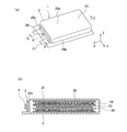
- the sealed secondary battery 1 shown in FIG. 1 includes a polymer matrix layer 3 and a detection unit 4.
- the unit cell 2 constituting the secondary battery 1 has a structure in which an electrode group 22 is accommodated inside a sealed exterior body 21.
- the electrode group 22 of the present embodiment is formed by laminating a positive electrode 23 and a negative electrode 24 with a separator 25 interposed therebetween, and the laminate is included in the outer package 21 together with the electrolytic solution.
- Leads are connected to the positive electrode 23 and the negative electrode 24, respectively, and their end portions project outside the exterior body 21 to constitute electrode terminals 26 and 27.
- the electrode terminals 26 and 27 are provided at one end of the exterior body 21 in the X direction.
- the secondary battery 1 of the present embodiment is a laminated battery using a laminated film such as an aluminum laminated foil as the outer package 21, and specifically, a laminated lithium ion secondary battery having a capacity of 1.44 Ah.
- the exterior body 21 has a plurality of wall portions including the wall portions 28a to 28c and a welded portion 29 formed on the three surrounding sides, and is formed in a thin rectangular parallelepiped shape as a whole.
- the X, Y, and Z directions correspond to the length direction, the width direction, and the thickness direction of the unit cell 2, respectively.
- the Z direction is also the thickness direction of the positive electrode 23 and the negative electrode 24, and the X direction and the Y direction are also directions orthogonal to the thickness direction.
- the polymer matrix layer 3 is attached to the outer surface of the wall portion 28a of the exterior body 21 that faces the electrode group 22 in the thickness direction of the positive electrode 23 and the negative electrode 24, that is, the Z direction (vertical direction in FIG. 1b). Yes.
- the outer surface of the wall portion 28 a corresponds to the upper surface of the exterior body 21.
- the polymer matrix layer 3 is opposed to the electrode group 22 with the wall portion 28 a interposed therebetween, and is disposed in parallel with the upper surface of the electrode group 22. Since the swelling of the unit cell 2 becomes large at the central portion (the central portion in the length direction and the width direction) of the wall portion 28a, it is preferable to attach the polymer matrix layer 3 so as to pass through the central portion.
- the polymer matrix layer 3 extends along the width direction, but is not limited thereto.
- the polymer matrix layer 3 contains a filler that changes the external field according to the deformation of the polymer matrix layer 3 dispersed therein. And the detection part 4 detects the change of the external field accompanying the deformation
- the polymer matrix layer 3 of the present embodiment is formed in a sheet shape from an elastomer material that can be flexibly deformed according to the swelling of the unit cell 2. When the secondary battery 1 is deformed due to the swelling of the unit cell 2, the polymer matrix layer 3 is deformed accordingly, and the change in the external field due to the deformation of the polymer matrix layer 3 is detected by the detection unit 4, Based on this, deformation of the secondary battery 1 can be detected with high sensitivity.
- the detection signal output from the detection unit 4 is sent to a control device (not shown), and when a change in the external field exceeding a set value is detected by the detection unit 4, the switching (not shown) connected to the control device.
- the circuit cuts off power and stops charging or discharging current. In this way, deformation of the secondary battery due to swelling of the unit cell 2 is detected with high sensitivity, and troubles such as rupture can be prevented in advance.
- electrode swelling and gas swelling can be distinguished and detected with high accuracy, deformation of the secondary battery due to gas swelling can be detected with high sensitivity, and trouble can be prevented accurately.
- the gas expansion of the unit cell 2 is caused by an increase in the internal pressure of the outer package 21 due to the decomposition gas of the electrolytic solution, and therefore tends to act uniformly in each of the X, Y, and Z directions.
- the electrode swelling is caused by a change in the thickness of the electrode group 22 due to a change in the volume of the active material, the action in the thickness direction of the positive electrode 23 and the negative electrode 24, that is, the Z direction is large. Therefore, in the present embodiment in which the polymer matrix layer 3 is attached to the wall portion 28a, electrode swelling is reflected in the detection result.
- the deformation of the secondary battery 1 with high sensitivity, it is possible to detect with high accuracy by distinguishing between the electrode bulge and the gas bulge as in the embodiments described later.
- a battery module including a plurality of single cells 2 is used in the secondary battery 1 for use where a high voltage is required, such as a power source for an electric vehicle.
- a battery module including a plurality of single cells 2 is used.
- a plurality of single cells 2 constitute an assembled battery and are accommodated in a housing.
- a battery module mounted on a vehicle is used in the form of a battery pack.
- a battery pack a plurality of battery modules are connected in series, and they are housed in a casing together with various devices such as a controller.
- the casing of the battery pack is formed in a shape suitable for in-vehicle use, for example, a shape that matches the underfloor shape of the vehicle.
- the detection unit 4 is disposed at a location where a change in the external field can be detected, and is preferably attached to a relatively rigid location that is not easily affected by the swelling of the unit cell 2.
- the detection part 4 is affixed on the inner surface of the housing 11 of the battery module facing the wall part 28a.
- the casing 11 of the battery module is formed of, for example, metal or plastic, and a laminate film may be used.
- the detection unit 4 is disposed close to the polymer matrix layer 3, but may be disposed away from the polymer matrix layer 3.
- the polymer matrix layer 3 contains a magnetic filler as the filler, and the detection unit 4 detects a change in the magnetic field as the external field.
- the polymer matrix layer 3 is preferably a magnetic elastomer layer in which a magnetic filler is dispersed in a matrix made of an elastomer component.
- the magnetic filler examples include rare earths, irons, cobalts, nickels, oxides, etc., but rare earths capable of obtaining higher magnetic force are preferable.
- the shape of the magnetic filler is not particularly limited, and may be spherical, flat, needle-like, columnar, or indefinite.
- the average particle size of the magnetic filler is preferably 0.02 to 500 ⁇ m, more preferably 0.1 to 400 ⁇ m, and still more preferably 0.5 to 300 ⁇ m. When the average particle size is smaller than 0.02 ⁇ m, the magnetic properties of the magnetic filler tend to be lowered, and when the average particle size exceeds 500 ⁇ m, the mechanical properties of the magnetic elastomer layer tend to be lowered and become brittle.
- the magnetic filler may be introduced into the elastomer after magnetization, but is preferably magnetized after being introduced into the elastomer. Magnetization after introduction into the elastomer facilitates control of the polarity of the magnet and facilitates detection of the magnetic field.
- thermoplastic elastomer a thermoplastic elastomer, a thermosetting elastomer, or a mixture thereof can be used.
- thermoplastic elastomer examples include styrene-based thermoplastic elastomer, polyolefin-based thermoplastic elastomer, polyurethane-based thermoplastic elastomer, polyester-based thermoplastic elastomer, polyamide-based thermoplastic elastomer, polybutadiene-based thermoplastic elastomer, polyisoprene-based thermoplastic elastomer, A fluororubber-based thermoplastic elastomer can be used.
- thermosetting elastomer examples include polyisoprene rubber, polybutadiene rubber, styrene-butadiene rubber, polychloroprene rubber, nitrile rubber, diene synthetic rubber such as ethylene-propylene rubber, ethylene-propylene rubber, butyl rubber, acrylic rubber, Non-diene synthetic rubbers such as polyurethane rubber, fluorine rubber, silicone rubber, epichlorohydrin rubber, and natural rubber can be mentioned.
- a thermosetting elastomer is preferable because it can suppress the sag of the magnetic elastomer accompanying heat generation and overload of the battery. More preferred is polyurethane rubber (also referred to as polyurethane elastomer) or silicone rubber (also referred to as silicone elastomer).
- Polyurethane elastomer is obtained by reacting polyol and polyisocyanate.
- an active hydrogen-containing compound and a magnetic filler are mixed, and an isocyanate component is mixed here to obtain a mixed solution.
- a liquid mixture can also be obtained by mixing a magnetic filler with an isocyanate component and mixing an active hydrogen-containing compound. The mixed liquid is poured into a mold subjected to a release treatment, and then heated to a curing temperature and cured to produce a magnetic elastomer.
- a magnetic elastomer can be produced by adding a magnetic filler to a silicone elastomer precursor, mixing it, putting it in a mold, and then heating and curing it. In addition, you may add a solvent as needed.
- isocyanate component that can be used in the polyurethane elastomer
- compounds known in the field of polyurethane can be used.
- the isocyanate component may be modified such as urethane modification, allophanate modification, biuret modification, and isocyanurate modification.
- Preferred isocyanate components are 2,4-toluene diisocyanate, 2,6-toluene diisocyanate, 4,4'-diphenylmethane diisocyanate, more preferably 2,4-toluene diisocyanate, 2,6-toluene diisocyanate.
- polyurethane those usually used in the technical field of polyurethane can be used.
- Polyester polyol such as polyester polyol, polycaprolactone polyol, reaction product of polyester glycol and alkylene carbonate such as polycaprolactone, and the like, and the reaction of the resulting reaction mixture with organic polyol.
- Polyester polycarbonate polyol reacted with dicarboxylic acid, esterification of polyhydroxyl compound and aryl carbonate High molecular weight polyol polycarbonate polyols obtained by the reaction can be mentioned. These may be used alone or in combination of two or more.
- Preferred active hydrogen-containing compounds are polytetramethylene glycol, polypropylene glycol, a copolymer of propylene oxide and ethylene oxide, 3-methyl-1,5-pentane adipate, more preferably a copolymer of polypropylene glycol, propylene oxide and ethylene oxide. It is a coalescence.
- the isocyanate component As a preferred combination of the isocyanate component and the active hydrogen-containing compound, as the isocyanate component, one or more of 2,4-toluene diisocyanate, 2,6-toluene diisocyanate, and 4,4′-diphenylmethane diisocyanate, active hydrogen
- the contained compound include polytetramethylene glycol, polypropylene glycol, a copolymer of propylene oxide and ethylene oxide, and one or more of 3-methyl-1,5-pentaneadipate.
- a combination of 2,4-toluene diisocyanate and / or 2,6-toluene diisocyanate as the isocyanate component and polypropylene glycol and / or a copolymer of propylene oxide and ethylene oxide as the active hydrogen-containing compound. is there.
- the polymer matrix layer 3 may be a foam containing dispersed filler and bubbles.
- a general resin foam can be used as the foam, but it is preferable to use a thermosetting resin foam in consideration of characteristics such as compression set.
- the thermosetting resin foam include a polyurethane resin foam and a silicone resin foam. Among these, a polyurethane resin foam is preferable.
- the above-mentioned isocyanate component and active hydrogen-containing compound can be used for the polyurethane resin foam.
- the amount of the magnetic filler in the magnetic elastomer is preferably 1 to 450 parts by weight, more preferably 2 to 400 parts by weight with respect to 100 parts by weight of the elastomer component. If it is less than 1 part by weight, it tends to be difficult to detect a change in the magnetic field, and if it exceeds 450 parts by weight, the magnetic elastomer itself may become brittle.
- a sealing material for sealing the polymer matrix layer 3 may be provided to the extent that the flexibility of the polymer matrix layer 3 is not impaired.
- a thermoplastic resin, a thermosetting resin, or a mixture thereof can be used as the sealing material.
- thermoplastic resin examples include styrene-based thermoplastic elastomers, polyolefin-based thermoplastic elastomers, polyurethane-based thermoplastic elastomers, polyester-based thermoplastic elastomers, polyamide-based thermoplastic elastomers, polybutadiene-based thermoplastic elastomers, polyisoprene-based thermoplastic elastomers, Fluorine-based thermoplastic elastomer, ethylene / ethyl acrylate copolymer, ethylene / vinyl acetate copolymer, polyvinyl chloride, polyvinylidene chloride, chlorinated polyethylene, fluororesin, polyamide, polyethylene, polypropylene, polyethylene terephthalate, polybutylene terephthalate, polystyrene, polybutadiene Etc.
- thermosetting resin examples include polyisoprene rubber, polybutadiene rubber, styrene / butadiene rubber, polychloroprene rubber, diene-based synthetic rubber such as acrylonitrile / butadiene rubber, ethylene / propylene rubber, ethylene / propylene / diene rubber, butyl rubber, Non-diene rubbers such as acrylic rubber, polyurethane rubber, fluorine rubber, silicone rubber, epichlorohydrin rubber, natural rubber, polyurethane resin, silicone resin, epoxy resin and the like can be mentioned. These films may be laminated, or may be a film including a metal foil such as an aluminum foil or a metal vapor deposition film in which a metal is vapor deposited on the film.
- a metal foil such as an aluminum foil or a metal vapor deposition film in which a metal is vapor deposited on the film.
- the polymer matrix layer 3 may be one in which fillers are unevenly distributed in the thickness direction.
- the polymer matrix layer 3 may have a structure composed of two layers of a region on one side with a relatively large amount of filler and a region on the other side with a relatively small amount of filler.
- the region on one side containing a large amount of filler the change in the external field with respect to small deformation of the polymer matrix layer 3 becomes large, so that the sensor sensitivity to a low internal pressure can be enhanced.
- the region on the other side with relatively little filler is relatively flexible and easy to move. By attaching this region, the polymer matrix layer 3 (especially the region on one side) is likely to be deformed.
- the filler uneven distribution ratio in the region on one side is preferably more than 50, more preferably 60 or more, and further preferably 70 or more. In this case, the filler uneven distribution rate in the other region is less than 50.
- the filler uneven distribution rate in the region on one side is 100 at the maximum, and the filler uneven distribution rate in the region on the other side is 0 at the minimum. Therefore, a laminate structure of an elastomer layer containing a filler and an elastomer layer not containing a filler may be used.
- the filler After introducing the filler into the elastomer component, it can be allowed to stand at room temperature or at a predetermined temperature, and then spontaneously settled according to the weight of the filler, by changing the temperature and time of standing.
- the filler uneven distribution rate can be adjusted.
- the filler may be unevenly distributed using a physical force such as centrifugal force or magnetic force.
- the polymer matrix layer may be constituted by a laminate composed of a plurality of layers having different filler contents.
- the filler uneven distribution rate is measured by the following method. That is, the cross section of the polymer matrix layer is observed at a magnification of 100 using a scanning electron microscope-energy dispersive X-ray analyzer (SEM-EDS). The area of the entire cross section in the thickness direction and the two areas obtained by dividing the cross section into two in the thickness direction are each subjected to elemental analysis of a metal element specific to the filler (for example, Fe element in the case of the magnetic filler of this embodiment). Find the abundance. For this abundance, the ratio of one area to the entire area in the thickness direction is calculated, and this is used as the filler uneven distribution rate in the one area. The filler uneven distribution rate in the other region is the same as this.
- SEM-EDS scanning electron microscope-energy dispersive X-ray analyzer
- the other region with relatively little filler may have a structure formed of a foam containing bubbles.
- the polymer matrix layer 3 is further easily deformed and the sensor sensitivity is enhanced.
- region of one side may be formed with the foam with the area
- Such a polymer matrix layer in which at least a part in the thickness direction is a foam is composed of a laminate composed of a plurality of layers (for example, a non-foamed layer containing a filler and a foamed layer not containing a filler). It doesn't matter.
- a magnetoresistive element for example, a magnetoresistive element, a Hall element, an inductor, an MI element, a fluxgate sensor, or the like can be used as the detection unit 4 that detects a change in the magnetic field.
- the magnetoresistive element include a semiconductor compound magnetoresistive element, an anisotropic magnetoresistive element (AMR), a giant magnetoresistive element (GMR), and a tunnel magnetoresistive element (TMR).
- AMR anisotropic magnetoresistive element
- GMR giant magnetoresistive element
- TMR tunnel magnetoresistive element
- the Hall element is preferable because it has high sensitivity over a wide range and is useful as the detection unit 4.
- the Hall element for example, EQ-430L manufactured by Asahi Kasei Electronics Corporation can be used.
- the polymer matrix layer 3 is affixed to the outer surface of 28b.
- the outer surface of the wall portion 28 b corresponds to the side surface of the exterior body 21.
- the polymer matrix layer 3 is opposed to the electrode group 22 with the wall portion 28b interposed therebetween, and is disposed perpendicular to the upper surface of the electrode group 22.
- the detection part 4 is affixed on the inner surface of the casing 11 of the battery module facing the wall part 28b.
- the electrode bulge has a large effect in the Z direction, in this embodiment in which the polymer matrix layer 3 is attached to the wall portion 28b, the electrode bulge is less likely to be reflected in the detection result, and the gas bulge is distinguished from the electrode bulge. It can be detected with high accuracy.
- the polymer matrix layer 3 is pasted on the outer surface of 28c.
- the outer surface of the wall portion 28 c corresponds to the side surface of the exterior body 21.
- the polymer matrix layer 3 is opposed to the electrode group 22 with the wall portion 28 c interposed therebetween, and is disposed perpendicular to the upper surface of the electrode group 22.
- the detection part 4 is affixed on the inner surface of the housing (not shown) of the battery module facing the wall part 28c.
- the electrode bulge has a large effect in the Z direction, in this embodiment in which the polymer matrix layer 3 is attached to the wall portion 28c, the electrode bulge is less likely to be reflected in the detection result, and the gas bulge distinguished from the electrode bulge is eliminated. It can be detected with high accuracy.
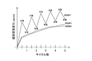
- Examples of the first to third embodiments The detection results for the swelling of the unit cells according to the first to third embodiments are shown in FIG. 4 as Examples 1 to 3, respectively.
- the cell is placed in a constant temperature bath at 25 ° C., left for 120 minutes, charged with a constant current of 4.3 V with a charging current of 1.44 A, and after reaching 4.3 V, the current value attenuates to 0.07 A. Until constant voltage charging. Then, after maintaining the open circuit state for 10 minutes, constant current discharge was performed to 3.0V with the electric current of 1.44A. This charging / discharging process was repeated 5 cycles, and a change in magnetic flux density (change in magnetic field) was detected by the Hall element after charging and discharging in each cycle.
- Example 1 the magnetic flux density greatly increases with charging, and the magnetic flux density significantly decreases with discharging. This is because the expansion and contraction of the electrode group 22 due to the volume change of the active material is reflected. Therefore, it can be said that 1st Embodiment is a suitable form for monitoring the electrode swelling accompanying charging / discharging. Further, in comparison at the time when the charge depth of each cycle is the same (for example, a full charge state or a complete discharge state), the magnitude of the magnetic flux density gradually increases as the number of cycles increases, and this phenomenon is caused by gas expansion. Since this is the cause, gas blistering can also be detected based on this.
- the third embodiment is a suitable form for monitoring gas expansion in a secondary battery that places importance on improving the energy density.
- the change in the external field due to the deformation of the polymer matrix layer 3 attached to each of the plurality of exterior bodies 21 is detected by a smaller number of detection units than the polymer matrix layer 3. 4 to detect.
- two unit cells 2 each having a polymer matrix layer 3 attached to the upper surface of the outer package 21 are arranged so as to overlap each other in the Z direction, and the polymer matrix layer is detected by the detection unit 4 arranged above them.
- transformation of 3 is detected. Accordingly, an advantageous effect such as space saving and weight reduction can be obtained by reducing the number of detection units 4, which is useful in configuring an assembled battery.
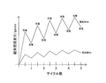
- Example of the fourth embodiment The detection results for the swelling of the unit cell according to the fourth embodiment are shown in FIG. 6 as Examples 4A and 4B, respectively.
- the detection procedure was performed in the same manner as in Example 1 and the like.
- Example 4A corresponds to the swelling of the upper unit cell close to the detection unit
- Example 4B corresponds to the swelling of the lower unit cell far from the detection unit. Since the behavior of the magnetic flux density change in Example 4A is the same as that in Example 1, detailed description thereof is omitted.
- Example 4B the change in magnetic flux density can be detected to the extent that the same tendency as in Example 4A is recognized. Therefore, it can be said that 4th Embodiment is a suitable form for detecting the electrode swelling and gas swelling of a some single cell by the detection part (hall element) of a fewer number than it.
- the change in the external field due to the deformation of the polymer matrix layer 3 attached to each of the plurality of exterior bodies 21 is detected by a smaller number of detection units than the polymer matrix layer 3. 4 to detect.
- two unit cells 2 each having a polymer matrix layer 3 attached to the side surface of the outer package 21 are arranged so as to overlap each other in the Z direction, and the polymer matrix layer is formed by the detection unit 4 arranged on the side thereof.
- transformation of 3 is detected. Accordingly, an advantageous effect such as space saving and weight reduction can be obtained by reducing the number of detection units 4, which is useful in configuring an assembled battery.
- Example of Fifth Embodiment The detection results for the swelling of the unit cell according to the fifth embodiment are shown in FIG. 8 as Examples 5A and 5B, respectively.
- the detection procedure was performed in the same manner as in Example 1 and the like.
- Examples 5A and 5B correspond to the swelling of the upper and lower unit cells, respectively. Since the behavior of the magnetic flux density change in Examples 5A and 5B is the same as that in Example 2, detailed description thereof is omitted. Thus, the equivalent magnetic flux density change can be detected for a plurality of single cells. Therefore, it can be said that 5th Embodiment is a suitable form for detecting the gas expansion
- the electrode group 22 ′ is formed by winding the positive electrode 23 and the negative electrode 24 through the separator 25 therebetween, and the wound body is included in the outer package 21 together with the electrolyte.
- the Z direction and the Y direction correspond to the thickness direction of the positive electrode 23 and the negative electrode 24, and the X direction corresponds to a direction orthogonal to the thickness direction.
- the polymer matrix layer 3 is formed on the outer surface of the wall portion 28b of the exterior body 21 that faces the electrode group 22 ′ in the Y direction (the left-right direction in FIG. 9b) as the thickness direction of the positive electrode 23 and the negative electrode 24.
- the outer surface of the wall portion 28 b corresponds to the side surface of the exterior body 21.
- the action of the electrode swelling is large in both the Z direction and the Y direction, and the polymer matrix layer 3 is attached to the outer surface of the wall portion 28b facing the electrode group 22 ′ in the Y direction.
- the blister is reflected in the detection result.
- the polymer matrix layer 3 is attached to the outer surface of the wall portion 28a instead of the wall portion 28b, the wall portion 28a faces the electrode group 22 'in the Z direction. Reflected.
- the electrode group 22 ′ has a wound structure, the swollen electrode can be detected by the polymer matrix layer 3 attached to the side surface of the outer package 21.
- a polymer matrix layer 3 is attached to the outer surface.
- the electrode group 22 ′ is formed by winding a positive electrode 23 and a negative electrode 24 with a separator 25 between them.
- the polymer matrix layer 3 is opposed to the electrode group 22 ′ with the wall portion 28c interposed therebetween, and is disposed perpendicular to the upper surface of the electrode group 22 ′.
- the electrode bulge is less likely to be reflected in the detection result, the gas bulge distinguished from the electrode bulge can be detected with high accuracy, and the energy density can be improved.
- the polymer matrix layer 3 is attached to the outer surface of the electrode group 22 ′ in the Y direction among the Z direction and the Y direction, which are the thickness directions of the positive electrode 23 and the negative electrode 24.
- the polymer matrix layer 3 is disposed inside the unit cell 2.
- the electrode bulge is mainly reflected in the detection result, the electrode bulge distinguished from the gas bulge can be detected with high accuracy.
- the exterior body 21 is a robust material such as a metal can, electrode swelling can be detected to a high degree, which is useful when a robust material is used for the exterior body.
- the same effect can be obtained when the polymer matrix layer 3 is attached to the outer surface of the electrode group 22 ′ in the Z direction.
- the polymer matrix layer 3 attached to the outer surface of the electrode group 22 ′ is preferably disposed in contact with the inner surface of the exterior body 21.
- changes in the external field due to deformation of the polymer matrix layer 3 attached to each of the plurality of electrode groups 22 ′ are detected using a smaller number of detection units 4 than the polymer matrix layer 3.
- two unit cells 2 each having a polymer matrix layer 3 attached to the side surface of the electrode group 22 ′ are arranged so as to overlap each other in the Z direction, and the polymer matrix is detected by the detection unit 4 arranged on the side of the two cells.
- a change in the external field accompanying each deformation of the layer 3 is detected. Accordingly, an advantageous effect such as space saving and weight reduction can be obtained by reducing the number of detection units 4, which is useful in configuring an assembled battery.
- the secondary battery cell is a lithium ion secondary battery
- the present invention is not limited thereto.
- the secondary battery cell used is not limited to a non-aqueous electrolyte secondary battery such as a lithium ion battery, and may be an aqueous electrolyte secondary battery such as a nickel-hydrogen battery.
- the polymer matrix layer may contain conductive fillers such as metal particles, carbon black, and carbon nanotubes as fillers, and the detector may detect changes in the electric field (changes in resistance and dielectric constant) as external fields. It is done.
Landscapes
- Chemical & Material Sciences (AREA)
- Chemical Kinetics & Catalysis (AREA)
- Electrochemistry (AREA)
- General Chemical & Material Sciences (AREA)
- Engineering & Computer Science (AREA)
- Manufacturing & Machinery (AREA)
- Physics & Mathematics (AREA)
- General Physics & Mathematics (AREA)
- Materials Engineering (AREA)
- Inorganic Chemistry (AREA)
- Secondary Cells (AREA)
- Sealing Battery Cases Or Jackets (AREA)
Abstract
Description
図1に示した密閉型二次電池1には、高分子マトリックス層3と、検出部4とが備え付けられている。この二次電池1を構成する単電池2は、密閉された外装体21の内部に電極群22が収容された構造を有する。本実施形態の電極群22は、正極23と負極24をそれらの間にセパレータ25を介して積層してなり、かかる積層体が電解液とともに外装体21に内包されている。正極23と負極24にはそれぞれリードが接続され、それらの端部が外装体21の外部に突出することにより電極端子26,27が構成されている。電極端子26,27は、外装体21のX方向の一端に設けられている。
第2実施形態は、以下に説明する事項を除いて、前述した実施形態と同様の構成及び作用であるため、共通点を省略して主に相違点について説明する。なお、既に説明した構成要素と同一の構成要素には、同一の符号を付し、重複した説明を省略する。後述する第3~第8実施形態についても、これと同様である。
図3のように、本実施形態では、正極23と負極24の厚み方向と直交する方向、具体的にはX方向(図3bの左右方向)に電極群22と対向する外装体21の壁部28cの外面に高分子マトリックス層3を貼り付けている。壁部28cの外面は、外装体21の側面に相当する。高分子マトリックス層3は、壁部28cを挟んで電極群22と相対し、電極群22の上面と垂直に配置されている。検出部4は、その壁部28cに対向する電池モジュールの筐体(不図示)の内面に貼り付けている。電極膨れはZ方向での作用が大きいため、高分子マトリックス層3を壁部28cに貼り付けた本実施形態では、電極膨れが検出結果に反映されにくくなり、電極膨れから区別されたガス膨れを精度良く検出できる。
第1~第3実施形態に係る単電池の膨れに対する検出結果を、それぞれ実施例1~3として図4に示す。単電池は、25℃の恒温槽に入れ、120分静置後、1.44Aの充電電流で4.3Vまで定電流充電し、4.3Vに到達後、0.07Aに電流値が減衰するまで定電圧充電を行った。その後、10分間の開回路状態を保持した後、1.44Aの電流で3.0Vまで定電流放電を行った。かかる充放電の工程を5サイクル繰り返し、各サイクルの充電後と放電後にホール素子によって磁束密度の変化(磁場の変化)を検出した。
図5のように、本実施形態では、複数の外装体21の各々に貼り付けられた高分子マトリックス層3の変形に伴う外場の変化を、その高分子マトリックス層3よりも少数の検出部4を用いて検出する。具体的には、外装体21の上面に高分子マトリックス層3を貼り付けた2つの単電池2をZ方向に重ねて配置し、それらの上方に配置した検出部4により、その高分子マトリックス層3の各々の変形に伴う外場の変化を検出する。これにより、検出部4の数を減らして省スペース化や軽量化といった有利な効果が得られるため、組電池を構成するうえで有用である。
第4実施形態に係る単電池の膨れに対する検出結果を、それぞれ実施例4A,4Bとして図6に示す。検出の手順は、実施例1などと同様にして行った。実施例4Aは、検出部に近い上側の単電池の膨れに相当し、実施例4Bは、検出部から遠い下側の単電池の膨れに相当する。実施例4Aの磁束密度変化の挙動は実施例1と同様であるため、詳しい説明は省略する。実施例4Bでは、実施例4Aと同様の傾向が認められる程度に磁束密度変化を検出できている。よって、第4実施形態は、複数の単電池の電極膨れやガス膨れを、それよりも少ない数の検出部(ホール素子)によって検出するのに好適な形態と言える。
図7のように、本実施形態では、複数の外装体21の各々に貼り付けられた高分子マトリックス層3の変形に伴う外場の変化を、その高分子マトリックス層3よりも少数の検出部4を用いて検出する。具体的には、外装体21の側面に高分子マトリックス層3を貼り付けた2つの単電池2をZ方向に重ねて配置し、それらの側方に配置した検出部4により、高分子マトリックス層3の各々の変形に伴う外場の変化を検出する。これにより、検出部4の数を減らして省スペース化や軽量化といった有利な効果が得られるため、組電池を構成するうえで有用である。
第5実施形態に係る単電池の膨れに対する検出結果を、それぞれ実施例5A,5Bとして図8に示す。検出の手順は、実施例1などと同様にして行った。実施例5A,5Bは、それぞれ上側,下側の単電池の膨れに相当する。実施例5A,5Bの磁束密度変化の挙動は実施例2と同様であるため、詳しい説明は省略する。このように、複数の単電池に対して同等の磁束密度変化を検出できている。よって、第5実施形態は、複数の単電池のガス膨れを、それよりも少ない数の検出部(ホール素子)によって検出するのに好適な形態と言える。
図9のように、本実施形態では、電極群22’が、正極23と負極24をそれらの間にセパレータ25を介して捲回してなり、かかる捲回体が電解液とともに外装体21に内包されている。このような捲回構造においては、Z方向及びY方向が、正極23と負極24の厚み方向に相当し、X方向が、その厚み方向と直交する方向に相当する。したがって、本実施形態では、正極23と負極24の厚み方向としてのY方向(図9bの左右方向)に電極群22’と対向する外装体21の壁部28bの外面に高分子マトリックス層3を貼り付けている。壁部28bの外面は、外装体21の側面に相当する。
図10のように、本実施形態では、正極23と負極24の厚み方向と直交する方向、即ちX方向(図10bの左右方向)に電極群22’と対向する外装体21の壁部28cの外面に高分子マトリックス層3を貼り付けている。電極群22’は、正極23と負極24をそれらの間にセパレータ25を介して捲回してなる。高分子マトリックス層3は、壁部28cを挟んで電極群22’と相対し、電極群22’の上面と垂直に配置されている。かかる構成では、電極膨れが検出結果に反映されにくくなり、電極膨れから区別されたガス膨れを精度良く検出できるとともに、エネルギー密度の向上を図ることができる。
図11のように、本実施形態では、正極23と負極24の厚み方向となるZ方向及びY方向のうち、Y方向にて電極群22’の外面に高分子マトリックス層3を貼り付けており、単電池2の内部に高分子マトリックス層3を配置している。かかる構成では、主として電極膨れが検出結果に反映されるため、ガス膨れから区別された電極膨れを精度良く検出できる。また、外装体21が金属缶などの堅牢な材質であっても、電極膨れを高度に検出できるため、外装体に堅牢な材質を用いる場合に有用である。Z方向にて電極群22’の外面に高分子マトリックス層3を貼り付けた場合も、これと同様の効果が得られる。電極群22’の外面に貼り付けた高分子マトリックス層3は、外装体21の内面と接して配置することが好ましい。
前述の実施形態では、二次電池セルがリチウムイオン二次電池である例を示したが、これに限られない。使用される二次電池セルは、リチウムイオン電池などの非水系電解液二次電池に限られず、ニッケル水素電池などの水系電解液二次電池であっても構わない。
2 単電池
3 高分子マトリックス層
4 検出部
21 外装体
22 電極群
23 正極
24 負極
25 セパレータ
26 電極端子
27 電極端子
28a 壁部
28b 壁部
28c 壁部
Claims (5)
- 密閉された外装体の内部に、正極と負極をそれらの間にセパレータを介して積層または捲回してなる電極群が収容された密閉型二次電池の変形検出方法において、
前記正極と負極の厚み方向もしくはその厚み方向と直交する方向に前記電極群と対向する前記外装体の壁部の外面に高分子マトリックス層を貼り付け、または、前記正極と負極の厚み方向にて前記電極群の外面に高分子マトリックス層を貼り付け、
前記高分子マトリックス層は、その高分子マトリックス層の変形に応じて外場に変化を与えるフィラーを分散させて含有するものであり、
前記高分子マトリックス層の変形に伴う前記外場の変化を検出部により検出することを特徴とする密閉型二次電池の変形検出方法。 - 前記高分子マトリックス層が前記フィラーとしての磁性フィラーを含有し、前記検出部が前記外場としての磁場の変化を検出する請求項1に記載の密閉型二次電池の変形検出方法。
- 電極端子に近い前記外装体の壁部の外面に前記高分子マトリックス層を貼り付ける請求項1または2に記載の密閉型二次電池の変形検出方法。
- 複数の前記外装体または複数の前記電極群の各々に貼り付けられた前記高分子マトリックス層の変形に伴う前記外場の変化を、その高分子マトリックス層よりも少数の前記検出部を用いて検出する請求項1~3いずれか1項に記載の密閉型二次電池の変形検出方法。
- 密閉された外装体の内部に、正極と負極をそれらの間にセパレータを介して積層または捲回してなる電極群が収容された密閉型二次電池において、
高分子マトリックス層と、検出部とが備え付けられ、
前記高分子マトリックス層は、前記正極と負極の厚み方向もしくはその厚み方向と直交する方向に前記電極群と対向する前記外装体の壁部の外面に貼り付けられ、または、前記正極と負極の厚み方向にて前記電極群の外面に貼り付けられ、
前記高分子マトリックス層は、その高分子マトリックス層の変形に応じて外場に変化を与えるフィラーを分散させて含有するものであり、
前記検出部が、前記高分子マトリックス層の変形に伴う前記外場の変化を検出することを特徴とする密閉型二次電池。
Priority Applications (3)
| Application Number | Priority Date | Filing Date | Title |
|---|---|---|---|
| CN201580029661.XA CN106463797A (zh) | 2014-07-08 | 2015-04-10 | 密闭型二次电池的变形检测方法及密闭型二次电池 |
| US15/315,187 US10186736B2 (en) | 2014-07-08 | 2015-04-10 | Deformation detection method for a sealed-type rechargeable battery and sealed-type rechargeable battery |
| KR1020167035733A KR101849288B1 (ko) | 2014-07-08 | 2015-04-10 | 밀폐형 2차 전지의 변형 검출 방법, 및, 밀폐형 2차 전지 |
Applications Claiming Priority (4)
| Application Number | Priority Date | Filing Date | Title |
|---|---|---|---|
| JP2014140307 | 2014-07-08 | ||
| JP2014-140307 | 2014-07-08 | ||
| JP2014-240176 | 2014-11-27 | ||
| JP2014240176A JP6200880B2 (ja) | 2014-07-08 | 2014-11-27 | 密閉型二次電池の変形検出方法、及び、密閉型二次電池 |
Publications (1)
| Publication Number | Publication Date |
|---|---|
| WO2016006293A1 true WO2016006293A1 (ja) | 2016-01-14 |
Family
ID=55063938
Family Applications (1)
| Application Number | Title | Priority Date | Filing Date |
|---|---|---|---|
| PCT/JP2015/061264 Ceased WO2016006293A1 (ja) | 2014-07-08 | 2015-04-10 | 密閉型二次電池の変形検出方法、及び、密閉型二次電池 |
Country Status (6)
| Country | Link |
|---|---|
| US (1) | US10186736B2 (ja) |
| JP (1) | JP6200880B2 (ja) |
| KR (1) | KR101849288B1 (ja) |
| CN (1) | CN106463797A (ja) |
| TW (1) | TWI570992B (ja) |
| WO (1) | WO2016006293A1 (ja) |
Cited By (1)
| Publication number | Priority date | Publication date | Assignee | Title |
|---|---|---|---|---|
| WO2018230268A1 (ja) * | 2017-06-12 | 2018-12-20 | 東洋ゴム工業株式会社 | 監視センサ、及び密閉型二次電池 |
Families Citing this family (7)
| Publication number | Priority date | Publication date | Assignee | Title |
|---|---|---|---|---|
| KR102000632B1 (ko) * | 2016-06-09 | 2019-10-01 | 주식회사 엘지화학 | 2차 전지 전극의 두께 변화 측정 장치 및 그를 장착한 2차 전지 |
| JP2018029029A (ja) * | 2016-08-19 | 2018-02-22 | 東洋ゴム工業株式会社 | 使用済み電池を用いた組電池の製造方法及び組電池 |
| KR102192676B1 (ko) | 2017-01-24 | 2020-12-17 | 주식회사 엘지화학 | 배터리 모듈 변형 예측 장치 |
| WO2018173360A1 (ja) * | 2017-03-24 | 2018-09-27 | 東洋ゴム工業株式会社 | 非水系二次電池の充電方法 |
| KR102771719B1 (ko) * | 2019-07-29 | 2025-02-25 | 에스케이온 주식회사 | 전지팩 |
| CN110702342B (zh) * | 2019-09-25 | 2021-10-01 | 广州市广珠电池有限公司 | 一种锂离子电池低温密封性的检测方法 |
| KR102886637B1 (ko) * | 2021-05-26 | 2025-11-14 | 주식회사 엘지에너지솔루션 | 배터리 관리 장치 및 방법 |
Citations (4)
| Publication number | Priority date | Publication date | Assignee | Title |
|---|---|---|---|---|
| JP2005063736A (ja) * | 2003-08-08 | 2005-03-10 | Nissan Motor Co Ltd | 薄型電池の異常検出装置 |
| WO2012073770A1 (ja) * | 2010-11-30 | 2012-06-07 | 東海ゴム工業株式会社 | 蓄電デバイス |
| JP2012234629A (ja) * | 2011-04-28 | 2012-11-29 | Hitachi Vehicle Energy Ltd | 蓄電装置 |
| JP2014098688A (ja) * | 2012-10-19 | 2014-05-29 | Toyo Tire & Rubber Co Ltd | 曲げセンサー |
Family Cites Families (6)
| Publication number | Priority date | Publication date | Assignee | Title |
|---|---|---|---|---|
| GB0119530D0 (en) | 2001-08-10 | 2001-10-03 | Nec Technologies Uk Ltd | Electrical cell protection |
| JP2009076265A (ja) | 2007-09-19 | 2009-04-09 | Panasonic Corp | 電池パック |
| RU2462794C2 (ru) * | 2008-04-11 | 2012-09-27 | Кавасаки Юкогё Кабусики Кайся | Герметичная аккумуляторная батарея прямоугольной формы и батарейный модуль, содержащий такую батарею |
| JP5417162B2 (ja) * | 2009-12-28 | 2014-02-12 | 株式会社日立製作所 | 蓄電装置 |
| JP5489797B2 (ja) | 2010-03-17 | 2014-05-14 | 三菱重工業株式会社 | 電池システム |
| WO2014061684A1 (ja) | 2012-10-19 | 2014-04-24 | 東洋ゴム工業株式会社 | センサーおよびその製造方法 |
-
2014
- 2014-11-27 JP JP2014240176A patent/JP6200880B2/ja not_active Expired - Fee Related
-
2015
- 2015-04-10 WO PCT/JP2015/061264 patent/WO2016006293A1/ja not_active Ceased
- 2015-04-10 US US15/315,187 patent/US10186736B2/en not_active Expired - Fee Related
- 2015-04-10 KR KR1020167035733A patent/KR101849288B1/ko not_active Expired - Fee Related
- 2015-04-10 CN CN201580029661.XA patent/CN106463797A/zh active Pending
- 2015-04-14 TW TW104111906A patent/TWI570992B/zh not_active IP Right Cessation
Patent Citations (4)
| Publication number | Priority date | Publication date | Assignee | Title |
|---|---|---|---|---|
| JP2005063736A (ja) * | 2003-08-08 | 2005-03-10 | Nissan Motor Co Ltd | 薄型電池の異常検出装置 |
| WO2012073770A1 (ja) * | 2010-11-30 | 2012-06-07 | 東海ゴム工業株式会社 | 蓄電デバイス |
| JP2012234629A (ja) * | 2011-04-28 | 2012-11-29 | Hitachi Vehicle Energy Ltd | 蓄電装置 |
| JP2014098688A (ja) * | 2012-10-19 | 2014-05-29 | Toyo Tire & Rubber Co Ltd | 曲げセンサー |
Cited By (1)
| Publication number | Priority date | Publication date | Assignee | Title |
|---|---|---|---|---|
| WO2018230268A1 (ja) * | 2017-06-12 | 2018-12-20 | 東洋ゴム工業株式会社 | 監視センサ、及び密閉型二次電池 |
Also Published As
| Publication number | Publication date |
|---|---|
| JP2016027537A (ja) | 2016-02-18 |
| US10186736B2 (en) | 2019-01-22 |
| KR20170009954A (ko) | 2017-01-25 |
| CN106463797A (zh) | 2017-02-22 |
| US20170200986A1 (en) | 2017-07-13 |
| TW201607106A (zh) | 2016-02-16 |
| JP6200880B2 (ja) | 2017-09-20 |
| KR101849288B1 (ko) | 2018-04-16 |
| TWI570992B (zh) | 2017-02-11 |
Similar Documents
| Publication | Publication Date | Title |
|---|---|---|
| JP6176632B2 (ja) | 組電池の異常判定方法及び組電池の異常判定装置 | |
| JP6200880B2 (ja) | 密閉型二次電池の変形検出方法、及び、密閉型二次電池 | |
| JP6186385B2 (ja) | 密閉型二次電池の劣化診断方法及び劣化診断システム | |
| JP6209173B2 (ja) | 密閉型二次電池の劣化診断方法及び劣化診断システム | |
| JP2017168422A (ja) | 密閉型二次電池の残容量予測方法及び残容量予測システム | |
| WO2018078912A1 (ja) | 密閉型二次電池の変形検出センサ、及び密閉型二次電池 | |
| TWI628830B (zh) | 利用使用完畢之電池的電池組之製造方法及電池組 | |
| WO2016080027A1 (ja) | 密閉型二次電池の変形検出センサの製造方法 | |
| WO2016006359A1 (ja) | 密閉型二次電池の劣化診断方法及び劣化診断システム | |
| WO2018173360A1 (ja) | 非水系二次電池の充電方法 | |
| JP2016031359A (ja) | 密閉型二次電池の変形検出センサおよびその製造方法、密閉型二次電池、ならびに密閉型二次電池の変形検出方法 | |
| WO2017158923A1 (ja) | 密閉型二次電池の残容量予測方法、残容量予測システム、電池内部情報の取得方法及び電池制御方法 | |
| JP2018044909A (ja) | 密閉型二次電池の変形検出センサ | |
| JP2018137162A (ja) | 密閉型二次電池の監視センサ、監視センサの製造方法、密閉型二次電池 | |
| JP2019219276A (ja) | 二次電池の変形検出センサ、密閉型二次電池、補正データの生成方法 | |
| WO2018230268A1 (ja) | 監視センサ、及び密閉型二次電池 | |
| JP2018044907A (ja) | 密閉型二次電池の変形検出センサ | |
| JP2019220348A (ja) | 二次電池の変形検出システム、方法及びプログラム |
Legal Events
| Date | Code | Title | Description |
|---|---|---|---|
| 121 | Ep: the epo has been informed by wipo that ep was designated in this application |
Ref document number: 15819171 Country of ref document: EP Kind code of ref document: A1 |
|
| WWE | Wipo information: entry into national phase |
Ref document number: 15315187 Country of ref document: US |
|
| ENP | Entry into the national phase |
Ref document number: 20167035733 Country of ref document: KR Kind code of ref document: A |
|
| NENP | Non-entry into the national phase |
Ref country code: DE |
|
| 122 | Ep: pct application non-entry in european phase |
Ref document number: 15819171 Country of ref document: EP Kind code of ref document: A1 |