WO2016002896A1 - ヘッド洗浄装置及びインクジェットプリンタ - Google Patents
ヘッド洗浄装置及びインクジェットプリンタ Download PDFInfo
- Publication number
- WO2016002896A1 WO2016002896A1 PCT/JP2015/069173 JP2015069173W WO2016002896A1 WO 2016002896 A1 WO2016002896 A1 WO 2016002896A1 JP 2015069173 W JP2015069173 W JP 2015069173W WO 2016002896 A1 WO2016002896 A1 WO 2016002896A1
- Authority
- WO
- WIPO (PCT)
- Prior art keywords
- cleaning
- storage tank
- head
- inkjet head
- wiping
- Prior art date
- Legal status (The legal status is an assumption and is not a legal conclusion. Google has not performed a legal analysis and makes no representation as to the accuracy of the status listed.)
- Ceased
Links
Images





Classifications
-
- B—PERFORMING OPERATIONS; TRANSPORTING
- B41—PRINTING; LINING MACHINES; TYPEWRITERS; STAMPS
- B41J—TYPEWRITERS; SELECTIVE PRINTING MECHANISMS, i.e. MECHANISMS PRINTING OTHERWISE THAN FROM A FORME; CORRECTION OF TYPOGRAPHICAL ERRORS
- B41J2/00—Typewriters or selective printing mechanisms characterised by the printing or marking process for which they are designed
- B41J2/005—Typewriters or selective printing mechanisms characterised by the printing or marking process for which they are designed characterised by bringing liquid or particles selectively into contact with a printing material
- B41J2/01—Ink jet
- B41J2/135—Nozzles
- B41J2/165—Prevention or detection of nozzle clogging, e.g. cleaning, capping or moistening for nozzles
- B41J2/16517—Cleaning of print head nozzles
- B41J2/16535—Cleaning of print head nozzles using wiping constructions
-
- B—PERFORMING OPERATIONS; TRANSPORTING
- B41—PRINTING; LINING MACHINES; TYPEWRITERS; STAMPS
- B41J—TYPEWRITERS; SELECTIVE PRINTING MECHANISMS, i.e. MECHANISMS PRINTING OTHERWISE THAN FROM A FORME; CORRECTION OF TYPOGRAPHICAL ERRORS
- B41J2/00—Typewriters or selective printing mechanisms characterised by the printing or marking process for which they are designed
- B41J2/005—Typewriters or selective printing mechanisms characterised by the printing or marking process for which they are designed characterised by bringing liquid or particles selectively into contact with a printing material
- B41J2/01—Ink jet
- B41J2/135—Nozzles
- B41J2/165—Prevention or detection of nozzle clogging, e.g. cleaning, capping or moistening for nozzles
- B41J2/16517—Cleaning of print head nozzles
- B41J2/16535—Cleaning of print head nozzles using wiping constructions
- B41J2/16541—Means to remove deposits from wipers or scrapers
-
- B—PERFORMING OPERATIONS; TRANSPORTING
- B41—PRINTING; LINING MACHINES; TYPEWRITERS; STAMPS
- B41J—TYPEWRITERS; SELECTIVE PRINTING MECHANISMS, i.e. MECHANISMS PRINTING OTHERWISE THAN FROM A FORME; CORRECTION OF TYPOGRAPHICAL ERRORS
- B41J2/00—Typewriters or selective printing mechanisms characterised by the printing or marking process for which they are designed
- B41J2/005—Typewriters or selective printing mechanisms characterised by the printing or marking process for which they are designed characterised by bringing liquid or particles selectively into contact with a printing material
- B41J2/01—Ink jet
- B41J2/135—Nozzles
- B41J2/165—Prevention or detection of nozzle clogging, e.g. cleaning, capping or moistening for nozzles
- B41J2/16517—Cleaning of print head nozzles
- B41J2/16552—Cleaning of print head nozzles using cleaning fluids
-
- B—PERFORMING OPERATIONS; TRANSPORTING
- B41—PRINTING; LINING MACHINES; TYPEWRITERS; STAMPS
- B41J—TYPEWRITERS; SELECTIVE PRINTING MECHANISMS, i.e. MECHANISMS PRINTING OTHERWISE THAN FROM A FORME; CORRECTION OF TYPOGRAPHICAL ERRORS
- B41J2/00—Typewriters or selective printing mechanisms characterised by the printing or marking process for which they are designed
- B41J2/005—Typewriters or selective printing mechanisms characterised by the printing or marking process for which they are designed characterised by bringing liquid or particles selectively into contact with a printing material
- B41J2/01—Ink jet
- B41J2/135—Nozzles
- B41J2/165—Prevention or detection of nozzle clogging, e.g. cleaning, capping or moistening for nozzles
- B41J2/16517—Cleaning of print head nozzles
- B41J2/16552—Cleaning of print head nozzles using cleaning fluids
- B41J2002/16558—Using cleaning liquid for wet wiping
-
- B—PERFORMING OPERATIONS; TRANSPORTING
- B41—PRINTING; LINING MACHINES; TYPEWRITERS; STAMPS
- B41J—TYPEWRITERS; SELECTIVE PRINTING MECHANISMS, i.e. MECHANISMS PRINTING OTHERWISE THAN FROM A FORME; CORRECTION OF TYPOGRAPHICAL ERRORS
- B41J2/00—Typewriters or selective printing mechanisms characterised by the printing or marking process for which they are designed
- B41J2/005—Typewriters or selective printing mechanisms characterised by the printing or marking process for which they are designed characterised by bringing liquid or particles selectively into contact with a printing material
- B41J2/01—Ink jet
- B41J2/135—Nozzles
- B41J2/165—Prevention or detection of nozzle clogging, e.g. cleaning, capping or moistening for nozzles
- B41J2/16517—Cleaning of print head nozzles
- B41J2002/16567—Cleaning of print head nozzles using ultrasonic or vibrating means
Definitions
- the present invention relates to a head cleaning device and an ink jet printer.
- the ink jet printer has a plurality of nozzles that eject ink. There are cases where dirt such as ink adheres to the ejection surface provided with the nozzle. For example, an ink jet printer that removes dirt on the discharge surface by a wiping member such as a wiper is known.
- the dirt on the wiper is removed by other members, for example.
- stains such as ink with increased viscosity may remain on the wiper.
- An example of a problem to be solved by the present invention is to provide a head cleaning device and an ink jet printer that can effectively clean a wiping member.
- a head cleaning device includes a storage tank, a wiping unit, and a cleaning unit.
- a cleaning liquid for cleaning the wiping unit is stored in the storage tank.
- the wiping unit has a wiping member for wiping the discharge surface. The cleaning unit cleans the wiping member in the cleaning liquid of the storage tank.
- the cleaning unit cleans the wiping member that wipes the ejection surface of the inkjet head using the cleaning liquid in the storage tank. Dirt adhering to the wiping member is taken into a large amount of cleaning liquid in the storage tank. As a result, the wiping member is effectively cleaned, and the dirt remaining on the wiping member is suppressed from adhering to the ejection surface of the inkjet head.
- the cleaning unit In the head cleaning apparatus, at least a part of the cleaning unit is immersed in the cleaning liquid in the storage tank, and the discharge surface and the wiping member come into contact with the discharge surface of the inkjet head and the wiping member. It is preferable to have a cleaning member for cleaning.
- the cleaning member cleans the ejection surface of the inkjet head and the wiping member. Thereby, the discharge surface and the wiping member are more effectively cleaned. If the discharge surface is wiped using a wiping member (for example, a wiper) while dirt such as ink remains attached to the discharge surface, the dirt may be pushed into the nozzle on the discharge surface, causing nozzle clogging. There is. Therefore, by cleaning the ejection surface of the ink jet head with the cleaning member, it is possible to suppress the occurrence of nozzle clogging due to dirt such as ink entering the nozzle. Furthermore, since one cleaning member cleans the ejection surface and the wiping member, the number of parts of the head cleaning device is reduced and the head cleaning device is saved in space.
- a wiping member for example, a wiper
- the wiping member has a contact portion that contacts the ejection surface of the inkjet head, and the contact portion is removed from the cleaning liquid in the storage tank when the wiping member wipes the ejection surface. It is preferably exposed and immersed in the cleaning liquid in the storage tank when the cleaning unit cleans the wiping member.
- the contact portion of the wiping member is immersed in the cleaning liquid in the storage tank when the cleaning unit cleans the wiping member. Thereby, the dirt adhering to the wiping member is taken into a large amount of cleaning liquid in the storage tank, and the wiping member is more effectively cleaned. Further, the contact portion of the wiping member is exposed from the cleaning liquid when the wiping member wipes the ejection surface of the inkjet head.
- the wiping member from which such dirt has been cleaned wipes the discharge surface, whereby the cleaning liquid remaining on the discharge surface cleaned by the cleaning unit is wiped off, and the discharge surface is easily dried. Thereby, the workability of cleaning the discharge surface is improved.
- the head cleaning device further includes an automatic level adjusting mechanism capable of changing the position of the liquid level of the cleaning liquid in the storage tank.
- the automatic level adjustment mechanism By changing the position of the liquid level of the cleaning liquid in the storage tank by the automatic level adjustment mechanism, when cleaning the discharge surface with the cleaning member, the contact position between the discharge surface and the cleaning member can be immersed in the cleaning liquid. Thereby, the discharge surface can be cleaned in the cleaning liquid, and the cleaning efficiency can be improved. Further, when wiping the discharge surface with the wiping member, the discharge surface can be reliably wiped by positioning the liquid surface of the cleaning liquid below the discharge surface. As described above, the position of the liquid surface of the cleaning liquid in the storage tank is changed by the automatic level adjustment mechanism, so that the cleaning of the discharge surface of the inkjet head using the cleaning member and the wiping member is performed more reliably. can do.
- the wiping unit includes a first position where the contact portion is exposed from the cleaning liquid in the storage tank, and a second position where the contact section is immersed in the cleaning liquid in the storage tank. It is preferable to have a first drive mechanism for moving the wiping member between the two.
- the first drive mechanism moves the wiping member between a first position where the contact portion is exposed from the cleaning liquid in the storage tank and a second position where the contact section is immersed in the cleaning liquid in the storage tank. Accordingly, the contact portion of the wiping member is immersed in the cleaning liquid without controlling the liquid level of the cleaning liquid. Furthermore, since the contact portion is moved to the second position by the first drive mechanism, the contact portion inadvertently contacts the ejection surface before being cleaned by the cleaning member, and the dirt remaining on the contact portion is inkjet. Adhering to the ejection surface of the head is suppressed.
- the head cleaning device further includes a control unit that controls the wiping unit so as to wipe the discharge surface after the cleaning member cleans the discharge surface.
- the cleaning surface and the dirt remaining on the discharge surface are removed by wiping the discharge surface with a wiping unit, thereby improving the cleaning effect of the discharge surface and making it easy to dry.
- the cleaning unit has a second drive mechanism that rotates or vibrates the cleaning member.
- the second drive mechanism rotates or vibrates the cleaning member.
- the discharge surface of the inkjet head and the wiping member are more effectively cleaned.
- the cleaning member at least partially immersed in the cleaning liquid in the storage tank rotates or vibrates, dirt transferred from the discharge surface and the wiping member to the cleaning member is taken into the cleaning liquid, and the cleaning member is cleaned.
- the second driving mechanism is magnetically coupled to the cleaning member via the wall of the storage tank and rotates or vibrates the cleaning member.
- the second drive mechanism is magnetically coupled to the cleaning member via the storage tank wall, and rotates or vibrates the cleaning member. For this reason, the cleaning member is rotated or vibrated without providing the second drive mechanism inside the storage tank or providing a member penetrating the wall of the storage tank. Therefore, the storage tank can be reduced in size, and the cleaning liquid can be prevented from leaking from the storage tank.
- An inkjet printer includes an inkjet head and the head cleaning device.
- the ink jet printer further includes a support member that supports the ink jet head and extends along a scanning direction.
- the ink jet head includes a scanning portion that ejects ink along the support member, and a scanning portion that is separated from the scanning portion. It is preferable that the head cleaning device cleans the ejection surface of the ink jet head located at the extension.
- the head cleaning device cleans the ejection surface of the inkjet head located at an extended portion that is out of the scanning portion that ejects ink. For this reason, the empty space of an inkjet printer is used effectively and an inkjet printer is reduced in size.
- the wiping member can be effectively cleaned.
- FIG. 1 is a diagram illustrating a configuration of an inkjet printer according to a first embodiment of the present invention.
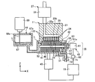
- FIG. 2 is a cross-sectional view showing the inkjet head and the cleaning station.
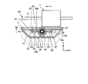
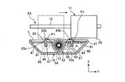
- FIG. 3 is a cross-sectional view showing the inkjet head and the cleaning station from a direction different from that in FIG.
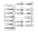
- FIG. 4 is a block diagram illustrating an example of the configuration of the controller.
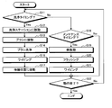
- FIG. 5 is a flowchart illustrating an example of the operation of the inkjet printer.
- FIG. 6 is a cross-sectional view showing the ink jet head and the cleaning station in the brush cleaning process.
- FIG. 7 is a bottom view showing the carriage and the brush.
- FIG. 1 is a diagram illustrating a configuration of an inkjet printer according to a first embodiment of the present invention.
- FIG. 2 is a cross-sectional view showing the inkjet head and the cleaning station.
- FIG. 3 is a cross-sectional view showing the inkjet head and the
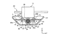
- FIG. 8 is a cross-sectional view showing the inkjet head and the cleaning station in the wiping process.
- FIG. 9 is a cross-sectional view showing an inkjet head and a cleaning station according to the second embodiment of the present invention.
- FIG. 10 is a modified example of the first embodiment, and is an explanatory view of the operation at the time of cleaning the ejection surface with a brush.
- FIG. 11 is a modified example of the first embodiment, and is an explanatory diagram of an operation at the time of wiping the ejection surface with a wiper.
- FIG. 1 is a diagram showing a configuration of an inkjet printer 10 according to a first embodiment of the invention.
- the inkjet printer 10 includes an inkjet head 11, a carriage 12, a bar 13, a table 14, a maintenance station 15, a cleaning station 16, and a controller 19.
- the bar 13 is an example of a support member.
- the cleaning station 16 is an example of a head cleaning device.
- the inkjet head 11 has an ejection surface 26 provided with a plurality of nozzles, and each nozzle ejects a corresponding ink.
- the inkjet printer 10 includes an inkjet head 11 having a plurality of nozzles respectively corresponding to cyan (C), magenta (M), yellow (Y), black (K), white, and other colors.
- the ink jet head 11 may be singular or plural.
- the carriage 12 holds the inkjet head 11.
- the bar 13 extends in the main scanning direction and is moved in the sub scanning direction by a drive mechanism using a motor or the like.
- a carriage 12 is movably attached to the bar 13. That is, the bar 13 supports the inkjet head 11 held by the carriage 12.
- the carriage 12 that holds the inkjet head 11 moves along the bar 13 (along the main scanning direction).
- an X axis, a Y axis, and a Z axis are defined.
- the X axis, the Y axis, and the Z axis are orthogonal to each other.
- the X axis is along the sub-scanning direction.
- the Y axis is along the main scanning direction.
- the Z axis is, for example, along the vertical direction.
- the medium M is placed on the table 14.
- the medium M is not limited to paper, and may be various articles such as plates, fabrics, and structures.
- the thickness of the medium M (the dimension in the direction along the Z axis) varies depending on the medium M.
- the medium M is fixed and positioned on the table 14 by suction or a pin, for example.
- the medium M is not limited to the table 14 and may be supported by another member such as a platen.
- the bar 13 is arranged on the table 14 with a predetermined interval.
- the carriage 12 includes a scanning portion (scanning path) A1 on the medium M placed on the table 14 along the bar 13, and two extension portions (overrun sections) A2 and A3 deviating from the scanning portion A1. , Move.
- the inkjet head 11 ejects ink onto the medium M placed on the table 14 when the carriage 12 is positioned at the scanning portion A1.
- the extension portions A2 and A3 are located at both ends of the bar 13. That is, the scanning portion A1 is located between the two extended portions A2 and A3.
- the maintenance station 15 moves with the bar 13 in the sub-scanning direction.
- the maintenance station 15 is disposed so as to face the ink jet head 11 of the carriage 12 located in one extension portion A2.
- the cleaning station 16 moves with the bar 13 in the sub-scanning direction.
- the cleaning station 16 is disposed so as to face the inkjet head 11 of the carriage 12 located in the other extension portion A3.
- FIG. 2 is a schematic diagram for explaining the cleaning of the inkjet head 11 and is a cross-sectional view showing the inkjet head 11 and the cleaning station 16.
- the inkjet head 11 includes a main body 21, a plurality of pressure chambers 22, a plurality of nozzles 23, a plurality of driving elements 24, and an ink supply channel 25.
- the ink supply channel 25 includes a supply unit 25a and a common unit 25b, and each is an example of a channel.
- the main body 21 is formed in a substantially rectangular parallelepiped.
- the shape of the main body 21 is not limited to this.
- the main body 21 has a substantially flat ejection surface 26.
- the discharge surface 26 faces downward and faces the table 14 and the medium M.
- the plurality of pressure chambers 22 are provided inside the main body 21.
- the pressure chambers 22 are arranged side by side in the direction along the X axis.
- the plurality of pressure chambers 22 connect the common portion 25 b of the ink supply channel 25 and the plurality of nozzles 23.
- the plurality of nozzles 23 are holes for discharging ink, and are provided on the discharge surface 26 of the main body 21. That is, ink is ejected from the ejection surface 26. Ink is an example of the first liquid.
- the nozzles 23 communicate with the common portion 25 b of the ink supply channel 25 through the corresponding pressure chambers 22.
- the nozzles 23 are arranged side by side in the direction along the X axis.
- the plurality of driving elements 24 form a part of the corresponding pressure chamber 22.
- the drive element 24 is a piezoelectric element, and changes the pressure of the ink in the pressure chamber 22 by being deformed when a voltage is applied.
- the drive element 24 is deformed to increase or decrease the pressure of the ink inside the pressure chamber 22 and eject ink droplets from the nozzle 23.
- the drive element 24 is not limited to that shown in FIG. 2, but can be applied to all drive methods classified into the conventional piezo method.
- the driving element 24 may be laminated on a diaphragm film that forms the pressure chamber 22.
- the thing of the thermal system called a thermal jet or a bubble jet (trademark) may be used.
- the ink supply channel 25 is a channel for connecting the pressure chambers 22 by the common unit 25b and supplying ink from the supply unit 25a to the pressure chambers 22 through the common unit 25b.
- the ink supply channel 25 is connected to an ink tank corresponding to the nozzle 23 via the ink supply unit 27.
- the ink supply unit 27 is an example of a liquid supply unit. The ink supply unit 27 supplies the ink in the ink tank to the pressure chamber 22 and the nozzle 23 via the ink supply channel 25.
- the ink supply unit 27 has a damper 31.
- the damper 31 is provided in a path between the ink tank and the inkjet head 11. The damper 31 relaxes ink pressure fluctuation when the ink enters and leaves the inkjet head 11.
- the maintenance station 15 shown in FIG. 1 periodically cleans the inkjet head 11 at a relatively short cycle, and maintains the quality of printing by the inkjet head 11. That is, the maintenance station 15 stabilizes the ink ejection of the inkjet head 11 by suppressing the contamination of the ejection surface 26 and keeping the ink viscosity of the nozzle 23 low.
- the maintenance station 15 has a cap and a wiper.
- the cap of the maintenance station 15 covers the ejection surface 26 of the inkjet head 11 from below and suppresses the ink of the nozzle 23 from drying.
- the inkjet head 11 performs flushing for discharging ink to the cleaning liquid in the cap.
- the wiper wipes the discharge surface 26.
- the configuration of the maintenance station is not limited to this, and it is sufficient that the maintenance function of the inkjet head 11 is provided.
- the cleaning station 16 periodically cleans the inkjet head 11 at a relatively long cycle, such as every day, every few days, or every week, and maintains the quality of printing by the inkjet head 11.
- the cleaning station 16 may clean the inkjet head 11 only in a predetermined case, not periodically.
- the cleaning station 16 removes the low-viscosity ink from the discharge surface 26 and the nozzle 23 and returns the inkjet head 11 to the initial state.
- the cleaning station 16 includes a storage tank 41, a cleaning unit 42, a brush drive mechanism 43, an automatic level adjustment mechanism 44, and an actuator 45.
- the brush drive mechanism 43 is an example of a second drive mechanism.
- the storage tank 41 is formed in a box shape with the upper end opened.
- the shape of the storage tank 41 is not limited to this.
- the cleaning liquid L is stored in the storage tank 41.
- the cleaning liquid L is an example of a second liquid, for example, a solvent.
- the storage tank 41 has a bottom wall 46 and a plurality of side walls 47.
- the plurality of side walls 47 rise from the edge of the bottom wall 46.
- the bottom wall 46 and the side wall 47 are made of, for example, a nonmagnetic material such as austenitic stainless steel (for example, SUS304) or a synthetic resin.
- the cleaning unit 42 includes a brush 51 and two support walls 52.
- the brush 51 is an example of a cleaning member.
- the brush 51 is immersed in the cleaning liquid L in the storage tank 41.
- the brush 51 includes a rotation shaft 54, a plurality of bristles 55, and a first magnet 56.
- the actuator 45 moves the storage tank 41 to the inkjet head 11 side when the inkjet head 11 comes to the cleaning position of the cleaning station 16, and holds the storage tank 41 at a position for the cleaning operation.
- Rotating shaft 54 extends in the direction along the X axis.
- the rotating shaft 54 is rotatably supported by a support wall 52 provided inside the storage tank 41.
- the bristles 55 are arranged on the rotation shaft 54 in the circumferential direction, and protrude from the rotation shaft 54 in the radial direction. Thereby, the hair 55 forms a substantially cylindrical shape.
- the bristles 55 are formed of a solvent-resistant synthetic resin such as polypropylene, nylon, and polycarbon.
- the first magnet 56 is attached to one end of the rotating shaft 54.
- the first magnet 56 faces the side wall 47 of the storage tank 41.
- the brush 51 is partially exposed from the cleaning liquid L.
- the entire brush 51 may be immersed in the cleaning liquid L.
- the brush drive mechanism 43 includes a first motor 61, a driver circuit 62, and a second magnet 63.
- the first motor 61 is driven by a driver circuit 62.
- the second magnet 63 is attached to the output shaft 61 a of the first motor 61.
- the second magnet 63 faces the first magnet 56 via the side wall 47 of the storage tank 41.
- the brush drive mechanism 43 is magnetically coupled to the brush 51 through the side wall 47 of the storage tank 41 by the first magnet 56 and the second magnet 63.
- the first motor 61 When the first motor 61 is driven, the second magnet 63 attached to the output shaft 61a rotates. Thereby, the rotating shaft 54 to which the first magnet 56 is attached also rotates. That is, the brush drive mechanism 43 rotates the brush 51.
- the rotating shaft 54 may pass through the side wall 47 of the storage tank 41 and may be directly rotated by the first motor 61.
- the bottom wall 46 and the side wall 47 may not be made of a nonmagnetic material, and may be made of, for example, a magnetic metal material.
- the automatic level adjustment mechanism 44 has an adjustment tank 67 and a supply tank 68.
- the adjustment tank 67 is connected to the storage tank 41 so that liquid can flow, and stores the cleaning liquid L.
- the supply tank 68 is disposed above the adjustment tank 67 and stores the cleaning liquid L.
- the communication tank 67 is provided with a communication port 67a that communicates with the atmosphere.
- a pipe 68 a extends downward from the bottom surface of the supply tank 68. The tip of the pipe 68 a is immersed in the liquid level of the cleaning liquid L stored in the adjustment tank 67.
- the automatic level adjustment mechanism 44 can automatically supply the cleaning liquid L to the storage tank 41 and keep the liquid level of the cleaning liquid L in the storage tank 41 constant.
- the height of the cleaning liquid L in the adjustment tank 67 is equal to the height of the cleaning liquid L in the storage tank 41.
- the storage tank 41 is provided with a discharge port 71 and a discharge valve 72.
- the discharge port 71 opens in the bottom wall 46 of the storage tank 41.
- the cleaning liquid L stored in the storage tank 41 is discharged from the discharge port 71.
- the discharge valve 72 is, for example, an electromagnetic valve. The discharge valve 72 blocks the outflow of the cleaning liquid L from the discharge port 71.
- the storage tank 41 is moved in the direction along the Z axis by the actuator 45.
- the actuator 45 moves the storage tank 41 in the Z-axis direction, thereby preventing collision with the moving inkjet head 11 and holding the position of the storage tank 41.
- FIG. 3 is a cross-sectional view showing the inkjet head 11 and the cleaning station 16 from a different direction from FIG.
- the cleaning station 16 further includes a wiping unit 81.
- the wiping unit 81 has two wipers 83 and a wiper drive mechanism 84.
- the wiper 83 is an example of a wiping member.
- the wiper drive mechanism 84 is an example of a first drive mechanism.
- the wiper 83 is formed of an elastic material such as synthetic rubber.
- the wiper 83 has a base 83a and a tip 83b thinner than the base 83a.
- the distal end portion 83b is an example of a contact portion and is more easily bent than the base portion 83a.
- the wiper drive mechanism 84 has two support shafts 87 and two second motors 88.
- the support shaft 87 is immersed in the cleaning liquid L of the storage tank 41 and is rotatably supported.
- the second motor 88 is disposed outside the storage tank 41 and rotates the support shaft 87.
- the second motor 88 may be directly coupled to the support shaft 87 or may be magnetically coupled.
- the base 83 a of the wiper 83 is attached to the support shaft 87.
- the wiper 83 is detachably attached to the support shaft 87 and may be replaceable.
- the wiper 83 is swung between the exposure position P1 and the immersion position P2.
- the exposure position P1 is an example of a first position.
- the immersion position P2 is an example of a second position.
- the wiper 83 at the exposure position P1 is indicated by a two-dot chain line.
- the wiper 83 extends in a direction along the Z axis, for example.
- the wiper 83 at the exposure position P1 is not limited to this, and may be inclined with respect to the Z axis.
- the tip 83b of the wiper 83 protrudes from the surface of the cleaning liquid L in the storage tank 41 and is exposed.
- the base 83a of the wiper 83 may be immersed in the cleaning liquid L, or may be partially exposed from the cleaning liquid L, for example.
- the wiper 83 extends in a direction along the Y axis, for example.
- the wiper 83 in the immersion position P2 is not restricted to this.
- the base 83 a and the tip 83 b of the wiper 83 are immersed in the cleaning liquid L of the storage tank 41.
- the tip 83b of the wiper 83 contacts the bristles 55 of the brush 51 at the immersion position P2. For this reason, when the brush 51 is rotated by the brush drive mechanism 43, the bristles 55 of the brush 51 rub the tip portion 83 b in the cleaning liquid L and clean it.
- FIG. 4 is a block diagram showing an example of the configuration of the controller 19.
- the controller 19 controls the operation of the inkjet printer 10.
- the controller 19 includes a head position control unit 101, a discharge control unit 102, a maintenance control unit 103, a wiper control unit 104, a brush control unit 105, and a storage tank position control unit 107.
- the head position control unit 101 controls the moving mechanism 112 via the driver circuit 111.
- the moving mechanism 112 includes, for example, a motor, a gear, and a belt, and moves the carriage 12 along the bar 13. That is, the head position control unit 101 controls the positions of the inkjet head 11 and the carriage 12 in the Y direction.
- the ejection control unit 102 controls the drive element 24 of the inkjet head 11 via the driver circuit 116. That is, the ejection control unit 102 controls the driver circuit 116 to supply a driving voltage from the driver circuit 116 to the driving element 24.
- the discharge controller 102 can selectively drive the plurality of drive elements 24. That is, the ejection control unit 102 can drive at least one driving element 24 and cause at least one nozzle 23 corresponding to the driving element 24 to eject a liquid such as ink. That is, the ejection control unit 102, the driver circuit 116, and the drive element 24 are an example of a first control mechanism.
- the maintenance control unit 103 controls the maintenance station 15.
- the maintenance control unit 103 controls, for example, a motor or a solenoid valve included in the maintenance station 15 via a driver circuit, thereby replacing the cleaning liquid stored in the cap, or wiping the ejection surface 26 of the inkjet head 11 with a wiper.
- a motor or a solenoid valve included in the maintenance station 15 via a driver circuit, thereby replacing the cleaning liquid stored in the cap, or wiping the ejection surface 26 of the inkjet head 11 with a wiper.
- the wiper control unit 104 controls the second motor 88 of the wiping unit 81 via the driver circuit 118. That is, the wiper control unit 104 causes the driver circuit 118 to drive the second motor 88 to swing the wiper 83 between the exposure position P1 and the immersion position P2.
- the brush control unit 105 controls the first motor 61 via the driver circuit 62.
- the brush control unit 105 rotates the brush 51 as described above by causing the driver circuit 62 to drive the first motor 61.
- the storage tank position control unit 107 controls the actuator 45 via the driver circuit 114.
- the actuator 45 moves the storage tank 41 in the direction along the Z axis. That is, the storage tank position control unit 107 controls the position of the storage tank 41 in the Z direction.
- the controller 19 the head position control unit 101, the discharge control unit 102, the maintenance control unit 103, the wiper control unit 104, the brush control unit 105, the storage tank position control unit 107, and the like included therein are an arithmetic device, a memory, and the like Hardware and programs that realize these predetermined functions.
- FIG. 5 is a flowchart illustrating an example of the operation of the inkjet printer 10.
- the operation of the inkjet printer 10 described below is executed by, for example, a predetermined program.
- the inkjet printer 10 performs printing on the medium M in accordance with, for example, a print command from an external personal computer or an operation unit provided in the inkjet printer 10. That is, the inkjet printer 10 moves the carriage 12 and the bar 13 in the sub-scanning direction and the main scanning direction based on the print command.
- the inkjet head 11 ejects ink from the nozzles 23 to the medium M, whereby an image is formed on the medium M.
- the carriage 12 moves between the scanning part A1 and the extension parts A2 and A3 along the bar 13 during the printing.
- the carriage 12 moves from one extension portion A2 through the scanning portion A1 to the other extension portion A3.
- the carriage 12 that has reached the other extension portion A3 returns to the original extension portion A2 (standby position). That is, the carriage 12 reverses the moving direction at the extended portions A2 and A3.
- the maintenance station 15 and the cleaning station 16 face the ink jet head 11 located in empty spaces (extended portions A2 and A3) necessary for the reversal of the carriage 12, respectively. For this reason, the ink jet printer 10 can be reduced in size.
- the controller 19 determines whether or not it is time to clean the inkjet head 11 while the inkjet printer 10 is operating as during printing (step S11). For example, the controller 19 counts time with a timer, and when the counted time reaches a predetermined period, it determines that it is time to clean the inkjet head 11 (step S11: Yes). The period is, for example, half a day or a time when ink precipitation or condensation occurs. When it is determined that it is time to clean the inkjet head 11, the timer time count is reset.
- the controller 19 determines that it is time to perform the cleaning.
- cleans the inkjet head 11 is not restricted to this.
- the head position control unit 101 of the controller 19 controls the moving mechanism 112 to move the carriage 12 to the extended portion A3. In other words, the carriage 12 is moved onto the cleaning station 16 (step S12).
- the storage tank position control unit 107 controls the actuator 45 to raise the storage tank 41. Thereby, as shown in FIG. 3, the discharge surface 26 of the inkjet head 11 contacts the bristles 55 of the brush 51 (step S13).
- FIG. 6 is a cross-sectional view showing the inkjet head 11 and the cleaning station 16 in the brush cleaning process. As shown in FIG. 6, the hair 55 of the brush 51 contacts the ejection surface 26 of the moving inkjet head 11.
- the brush control unit 105 controls the brush drive mechanism 43 and the brush 51 is rotated.
- the brush 51 may be rotated only in the forward rotation direction, or may be rotated in the forward / reverse rotation direction by reversing the rotation direction at a predetermined cycle.
- the bristles 55 of the rotating brush 51 remove the dirt adhering to the ejection surface 26 of the inkjet head 11 (step S14).
- the portion exposed from the cleaning liquid L of the brush 51 rubs and cleans the ejection surface 26 of the inkjet head 11.
- the brush 51 winds up the cleaning liquid L by rotating. Thereby, the cleaning liquid L is bathed on the discharge surface 26 and the discharge surface 26 is cleaned. Furthermore, since a part of the brush 51 is immersed in the cleaning liquid L, the many hairs 55 of the brush 51 include the cleaning liquid L.
- the bristles 55 of the brush 51 containing the cleaning liquid L rub against the discharge surface 26 of the inkjet head 11, so that the discharge surface 26 is effectively cleaned.
- the discharge surface 26 may be immersed in the cleaning liquid L.
- the concentration of ink attached to the discharge surface 26 is reduced.
- the brush 51 effectively rubs the discharge surface 26 by rubbing the discharge surface 26 while being immersed in the cleaning liquid L.
- the wiper 83 is basically disposed at the immersion position P2. For this reason, the bristles 55 of the rotating brush 51 rub the tip 83b of the wiper 83 in the cleaning liquid L to remove the dirt adhering to the tip 83b. Dirt on other parts of the wiper 83 is also removed by the cleaning liquid L. Further, the wiper 83 does not contact the moving inkjet head 11. Thus, when the brush 51 cleans the wiper 83, the wiper 83 is immersed in the cleaning liquid L in the storage tank 41.
- the dirt on the ejection surface 26 of the inkjet head 11 and the dirt on the tip 83b of the wiper 83 removed by the brush 51 are taken into the cleaning liquid L. That is, even if dirt adheres to the hair 55 of the brush 51, the brush 51 rotates in the cleaning liquid L, so that the dirt on the hair 55 is removed by the cleaning liquid L.
- FIG. 7 is a bottom view showing the carriage 12 and the brush 51.
- the entire ejection surface 26 can be cleaned by making the length of the brush 51 (the dimension along the X axis) larger than the length of the inkjet head 11.
- the width (diameter, dimension along the Y axis) of the brush 51 may be smaller than the width of the inkjet head 11 and can be reduced in size.
- the length of the wiper 83 the dimension along the X axis
- the width of the wiper 83 (the dimension along the Y axis) may be smaller than the width of the inkjet head 11 and can be downsized.
- FIG. 8 is a cross-sectional view showing the inkjet head 11 and the cleaning station 16 in the wiping process.
- the wiper control unit 104 controls the second motor 88 to move the wiper 83 to the exposure position P1.
- the tip 83b of the wiper 83 is exposed from the surface of the cleaning liquid L.
- the head position control unit 101 controls the moving mechanism 112 to move the inkjet head 11 in the direction along the Y axis.
- the tip 83b of the wiper 83 contacts the ejection surface 26 of the moving inkjet head 11.
- the tip 83b of the wiper 83 removes the cleaning liquid L and dirt remaining on the ejection surface 26 by wiping the ejection surface 26 of the moving inkjet head 11 (step S16). Thereby, the discharge surface 26 is cleaned and easily dried.
- the controller 19 controls the head position control unit 101 and the wiper control unit 104 to thereby control the discharge surface 26 by the wiper 83. Control is performed to perform wiping (step S16).
- the controller 19 is an example of a control unit.
- the head position control unit 101 controls the moving mechanism 112 to move the carriage 12 to the extension portion A2 (standby position) (step S17).
- the cleaning of the inkjet head 11 by the cleaning station 16 is completed.
- step S11 determines whether it is time to perform maintenance of the inkjet head 11 (step S18). For example, the controller 19 counts time with another timer, and when the counted time reaches a predetermined period, it determines that it is time to perform maintenance of the inkjet head 11 (step S18: Yes). The period is shorter than the period for determining the timing for cleaning the inkjet head 11. If it is determined that it is time to perform maintenance of the inkjet head 11, the timer count is reset.
- the controller 19 may determine that it is time to perform maintenance of the inkjet head 11 when it is determined that the viscosity of the ink inside the inkjet head 11 has reached a predetermined viscosity of about 20 millipascal seconds or less.
- standard judged that it is a timing which performs the maintenance of the inkjet head 11 is not restricted to this.
- the ejection control unit 102 of the controller 19 controls the drive element 24 in a state where the carriage 12 is in the extended portion A ⁇ b> 2 (standby position). Is vibrated slightly (step S19).
- the driving element 24 raises or lowers the pressure of the ink in the pressure chamber 22, but the ink is not ejected from the nozzle 23. Due to the minute vibration, the ink meniscus in the nozzle 23 vibrates, and the drying and viscosity increase of the ink in the vicinity of the nozzle 23 are suppressed.
- the minute vibration of the drive element 24 is not limited to during maintenance, but may be always performed during operation of the inkjet printer 10.
- the ejection control unit 102 controls the drive element 24 to perform flushing for ejecting ink from the nozzles 23 (step S20).
- the ink is discharged from the nozzle 23 to the cleaning liquid for the cap of the maintenance station 15.
- ink whose viscosity has increased due to drying in the vicinity of the nozzle 23 is discharged, and clogging of the nozzle 23 and flying bending of ink droplets are suppressed.
- the maintenance control unit 103 wipes the ejection surface 26 of the inkjet head 11 with the wiper of the maintenance station 15 (step S21). Thereby, dirt such as ink and dust attached to the ejection surface 26 is removed.
- the maintenance station 15 may select and perform at least one of micro vibration (step S19), flushing (step S20), and wiping (step S21).
- the maintenance station 15 may suck the cleaning liquid for the cap from the nozzle 23 on the ejection surface 26 of the inkjet head 11 covered with the cap. As a result, ink and stains with increased viscosity inside the inkjet head 11 are removed.
- the controller 19 repeats the cleaning (steps S11 to S17) and the maintenance (steps S18 to S21) of the inkjet head 11 until the operation of the inkjet printer 10 is completed (step S22). Thereby, the inkjet head 11 is kept clean and maintains the printing quality.
- the precipitation of the ink pigment in the ink tube is performed by providing an annular flow path between the damper 31 and the ink tank to circulate the ink. It is suppressed. The occurrence of contamination in the damper 31 is suppressed by flushing (step S20) in the maintenance station 15.
- Occurrence of contamination on the ejection surface 26 of the inkjet head 11 is suppressed by brush cleaning (step S14) in the cleaning station 16.
- the thickening of the ink meniscus at the nozzle 23 is suppressed by flushing at the maintenance station 15 (step S20).
- the occurrence of dirt or the like that may cause a printing failure of the inkjet head 11 is suppressed by the maintenance station 15 and the cleaning station 16.
- the ink jet head 11 is effectively maintained by combining the maintenance station 15 and the cleaning station 16.
- the cleaning unit 42 uses the cleaning liquid L in the storage tank 41 to clean the wiper 83 that wipes the ejection surface 26 of the inkjet head 11.
- the dirt adhering to the wiper 83 is taken into a large amount of the cleaning liquid L in the storage tank 41.
- the wiper 83 is effectively cleaned, and dirt remaining on the wiper 83 is suppressed from adhering to the ejection surface 26 of the inkjet head 11.
- the brush 51 may be vibrated by the brush drive mechanism 43.
- the brush 51 rubs and cleans the ejection surface 26 of the inkjet head 11 by vibrating.
- the method of cleaning by bringing the brush 51 into contact with the ejection surface 26 as in the first embodiment described above is particularly effective when either emulsion ink or ultraviolet curable ink is ejected from the ejection surface 26 as ink.
- Emulsion ink and ultraviolet curable ink once cured, have high weather resistance and are difficult to remove by subsequent washing.
- the ink is not sufficiently cleaned on the discharge surface of the ink jet head and is cured while adhering to the discharge surface, it is difficult to remove the ink from the discharge surface even by subsequent cleaning. Therefore, it is important that the cleaning of the ejection surface of the inkjet head is performed properly at an appropriate time.
- the type of solvent may be appropriately selected according to the type of ink.
- FIG. 9 is a cross-sectional view showing the inkjet head 11 and the cleaning station 16 according to the second embodiment.
- the cleaning unit 42 in the second embodiment includes an ultrasonic cleaning device 121 instead of the brush 51.
- the ultrasonic cleaning device 121 is attached to the storage tank 41 and propagates ultrasonic waves to the cleaning liquid L stored in the storage tank 41.
- the ultrasonic wave cleans the ejection surface 26 of the inkjet head 11 immersed in the cleaning liquid L and the wiper 83.
- the cleaning unit 42 may clean the ejection surface 26 and the wiper 83 of the inkjet head 11 without contact. Moreover, the cleaning unit 42 may include both the brush 51 of the first embodiment and the ultrasonic cleaning device 121 of the second embodiment.
- the wiping unit 81 of the second embodiment has one wiper 83.
- the number of wipers 83 may be two as in the first embodiment, one as in the second embodiment, or another number.
- the automatic level adjusting mechanism 44 may change the position of the liquid surface of the cleaning liquid L in the storage tank 41 as necessary. That is, the level of the cleaning liquid L in the storage tank 41 is equal to the level of the cleaning liquid L in the adjustment tank 67 of the automatic level adjustment mechanism 44, and thus the level of the cleaning liquid L in the adjustment tank 67. May adjust the height of the liquid level of the cleaning liquid L in the storage tank 41.
- the automatic level adjustment mechanism 44 may be configured so that the supply tank 68 can be moved up and down.
- the supply tank 68 of the automatic level adjusting mechanism 44 is configured to be movable up and down
- the supply tank 68 is raised and the tip of the pipe 68a is moved.
- the pressure in the supply tank 68 rises, so that the cleaning liquid L in the supply tank 68 can be supplied to the adjustment tank 67 by this change in pressure.
- the liquid level of L can be raised. Thereby, the liquid level of the cleaning liquid L in the storage tank 41 can be raised.
- the supply tank 68 is lowered to lower the height of the tip of the pipe 68a and the discharge valve 72 of the storage tank 41 is opened. A part of the cleaning liquid L stored in the storage tank 41 is discharged from the discharge port 71. Thereby, the liquid level of the cleaning liquid L in the storage tank 41 can be lowered together with the liquid level of the cleaning liquid L in the adjustment tank 67.
- the liquid level is adjusted according to the step at the time of cleaning the inkjet head 11.
- the height of the surface may be different.
- the level of the cleaning liquid L is changed by the automatic level adjustment mechanism 44 between the brush cleaning by the brush 51 and the wiping by the wiper 83. It may be allowed.
- FIG. 10 is a modified example of the first embodiment, and is an explanatory view of the operation at the time of cleaning the discharge surface 26 with the brush 51.
- the cleaning liquid L is set so that the liquid level of the cleaning liquid L in the storage tank 41 is higher than the contact position between the discharge surface 26 and the brush 51.
- the liquid level may be adjusted by the automatic level adjusting mechanism 44.
- the height of the liquid surface of the cleaning liquid L in the storage tank 41 is set to a height at which the contact position between the discharge surface 26 and the brush 51 is immersed.
- the ejection surface 26 can be cleaned in the cleaning liquid L. Thereby, cleaning efficiency can be improved.
- FIG. 11 is a modified example of the first embodiment, and is an explanatory view of the operation when the wiper 83 wipes the discharge surface 26. Further, when the ejection surface 26 of the inkjet head 11 is wiped by the wiper 83, the level of the liquid surface is set so that the liquid level of the cleaning liquid L in the storage tank 41 is located below the tip 83 b of the wiper 83. May be lowered. That is, the liquid level of the cleaning liquid L may be adjusted by the automatic level adjusting mechanism 44 so that the position of the liquid level of the cleaning liquid L in the storage tank 41 is located below the discharge surface 26.
- the wiper 83 wipes the discharge surface 26 by wiping off the cleaning liquid L adhering to the discharge surface 26 of the inkjet head 11, the liquid surface of the cleaning liquid L is positioned below the discharge surface 26.
- the discharge surface 26 can be wiped off reliably.
- the method of adjusting the height of the cleaning liquid L by the automatic level adjusting mechanism 44 may be performed by moving the supply tank 68 up and down.
- the automatic level adjustment mechanism 44 may be provided with supply means for the cleaning liquid L such as a pump, and the cleaning liquid L may be supplied to the adjustment tank 67 directly from the supply means or via the supply tank 68.
- the cleaning liquid L supply means and supplying the cleaning liquid L to the adjustment tank 67, the level of the cleaning liquid L in the adjustment tank 67 can be adjusted, and the cleaning liquid L in the storage tank 41 can be adjusted.
- the height of the liquid level can be adjusted.
- the embodiments of the present invention described above do not limit the scope of the invention, but are merely examples included in the scope of the invention. Further, the schematic diagram does not show the actual structure of the ink jet head, and the ink flow path, the ink driving element, and the like are different from the actual shape. An embodiment of the present invention is different from the above-described embodiment in that, for example, at least a part of a specific application, structure, shape, action, and effect is changed, omitted, and within the scope of the invention. It may be added.
- a part of the brush 51 of the cleaning unit 42 may protrude from the side wall 47 of the storage tank 41.
- the position control of the storage tank 41 by the actuator 45 may not be performed.
Landscapes
- Ink Jet (AREA)
Abstract
Description
以下に、第1実施形態について、図1~図8を参照して説明する。なお、実施形態に係る構成要素や、当該要素の説明について、複数の表現を併記することがある。当該構成要素及び説明について、記載されていない他の表現がされることは妨げられない。さらに、複数の表現が記載されない構成要素及び説明について、他の表現がされることは妨げられない。
以下に、第2実施形態について、図9を参照して説明する。なお、以下の実施形態の説明において、既に説明された構成要素と同様の機能を持つ構成要素は、当該既述の構成要素と同じ符号が付され、さらに説明が省略される場合がある。また、同じ符号が付された複数の構成要素は、全ての機能及び性質が共通するとは限らず、各実施形態に応じた異なる機能及び性質を有していても良い。
11…インクジェットヘッド
13…バー
16…洗浄ステーション
19…コントローラ
23…ノズル
24…駆動素子
25…インク供給流路
26…吐出面
27…インク供給部
41…貯留槽
42…洗浄ユニット
43…ブラシ駆動機構
45…アクチュエータ
47…側壁
51…ブラシ
61…第1のモータ
81…払拭ユニット
83…ワイパー
83a…基部
83b…先端部
84…ワイパー駆動機構
121…超音波洗浄装置
A1…走査部分
A2,A3…延長部分
L…洗浄液
P1…露出位置
P2…浸漬位置
Claims (10)
- インクジェットヘッドのインクを吐出する吐出面を拭く払拭部材を有した払拭ユニットと、
前記払拭ユニットを洗浄するための洗浄液が貯められる貯留槽と、
前記貯留槽の前記洗浄液中において前記払拭部材を洗浄する洗浄ユニットと、
を具備することを特徴とするヘッド洗浄装置。 - 前記洗浄ユニットは、少なくとも一部が前記貯留槽の前記洗浄液に浸漬され、前記インクジェットヘッドの前記吐出面と、前記払拭部材と、に接触して前記吐出面と前記払拭部材とを洗浄する洗浄部材を有した、請求項1に記載のヘッド洗浄装置。
- 前記払拭部材は、前記インクジェットヘッドの前記吐出面に接触する接触部を有し、
前記接触部は、前記払拭部材が前記吐出面を拭くときに前記貯留槽の前記洗浄液から露出させられ、前記洗浄ユニットが前記払拭部材を洗浄するときに前記貯留槽の前記洗浄液に浸漬される、
請求項2に記載のヘッド洗浄装置。 - 前記貯留槽における前記洗浄液の液面の位置を変化させることができる自動レベル調整機構をさらに有する請求項3に記載のヘッド洗浄装置。
- 前記払拭ユニットは、前記接触部が前記貯留槽の前記洗浄液から露出させられる第1の位置と、前記接触部が前記貯留槽の前記洗浄液に浸漬される第2の位置と、の間で前記払拭部材を移動させる第1の駆動機構を有する、請求項3に記載のヘッド洗浄装置。
- 前記洗浄部材が前記吐出面を洗浄した後に、前記吐出面を拭くように前記払拭ユニットを制御する制御部を具備する請求項2~請求項5のいずれか一つに記載のヘッド洗浄装置。
- 前記洗浄ユニットは、前記洗浄部材を回転又は振動させる第2の駆動機構を有する、請求項2~請求項5のいずれか一つに記載のヘッド洗浄装置。
- 前記第2の駆動機構は、前記貯留槽の壁を介して前記洗浄部材に磁気的に結合され、前記洗浄部材を回転又は振動させる請求項7に記載のヘッド洗浄装置。
- 前記インクジェットヘッドと、
請求項1~請求項5のいずれか一つに記載のヘッド洗浄装置と、
を具備することを特徴とするインクジェットプリンタ。 - 前記インクジェットヘッドを支持し、走査方向に沿って延びる支持部材をさらに具備し、
前記インクジェットヘッドは前記支持部材に沿って、インクの吐出を行う走査部分と、当該走査部分から外れた延長部分と、を移動可能であり、
前記ヘッド洗浄装置は、前記延長部分に位置する前記インクジェットヘッドの前記吐出面を洗浄する、
請求項9に記載のインクジェットプリンタ。
Priority Applications (2)
| Application Number | Priority Date | Filing Date | Title |
|---|---|---|---|
| US15/323,103 US9895895B2 (en) | 2014-07-03 | 2015-07-02 | Head washing device and inkjet printer |
| JP2016531453A JP6535667B2 (ja) | 2014-07-03 | 2015-07-02 | ヘッド洗浄装置及びインクジェットプリンタ |
Applications Claiming Priority (2)
| Application Number | Priority Date | Filing Date | Title |
|---|---|---|---|
| JP2014-138137 | 2014-07-03 | ||
| JP2014138137 | 2014-07-03 |
Publications (1)
| Publication Number | Publication Date |
|---|---|
| WO2016002896A1 true WO2016002896A1 (ja) | 2016-01-07 |
Family
ID=55019423
Family Applications (1)
| Application Number | Title | Priority Date | Filing Date |
|---|---|---|---|
| PCT/JP2015/069173 Ceased WO2016002896A1 (ja) | 2014-07-03 | 2015-07-02 | ヘッド洗浄装置及びインクジェットプリンタ |
Country Status (3)
| Country | Link |
|---|---|
| US (1) | US9895895B2 (ja) |
| JP (1) | JP6535667B2 (ja) |
| WO (1) | WO2016002896A1 (ja) |
Cited By (7)
| Publication number | Priority date | Publication date | Assignee | Title |
|---|---|---|---|---|
| JP2017064921A (ja) * | 2015-09-28 | 2017-04-06 | ローランドディー.ジー.株式会社 | インクジェットプリンタ |
| JP2018079684A (ja) * | 2016-11-10 | 2018-05-24 | 株式会社リコー | ヘッド清掃装置、ヘッドメンテナンス装置、液体を吐出する装置 |
| JP2019142145A (ja) * | 2018-02-22 | 2019-08-29 | 株式会社リコー | 払拭装置、ヘッドメンテナンス装置、液体を吐出する装置 |
| US11400719B2 (en) | 2020-01-07 | 2022-08-02 | Seiko Epson Corporation | Liquid ejecting apparatus and maintenance method for liquid ejecting apparatus |
| US20240042765A1 (en) * | 2022-08-03 | 2024-02-08 | Heidelberger Druckmaschinen Ag | Method of cleaning nozzle surfaces of an inkjet print head assembly |
| JP2024045701A (ja) * | 2019-12-12 | 2024-04-02 | 株式会社キーエンス | インクジェット記録システム |
| JP7512940B2 (ja) | 2021-03-31 | 2024-07-09 | ブラザー工業株式会社 | 印刷装置及び印刷装置の洗浄アッセンブリ |
Families Citing this family (3)
| Publication number | Priority date | Publication date | Assignee | Title |
|---|---|---|---|---|
| US10766261B2 (en) * | 2018-03-19 | 2020-09-08 | Ricoh Company, Ltd. | Head cleaning device and liquid discharge apparatus |
| EP3972756A2 (en) * | 2019-05-23 | 2022-03-30 | General Electric Company | Cleaning systems for additive manufacturing apparatuses and methods for using the same |
| US11052662B2 (en) | 2019-12-06 | 2021-07-06 | Xerox Corporation | Inkjet printhead wiper cleaning system having cleaning fluid supplied brush |
Citations (9)
| Publication number | Priority date | Publication date | Assignee | Title |
|---|---|---|---|---|
| JPH04219251A (ja) * | 1990-01-12 | 1992-08-10 | Hewlett Packard Co <Hp> | インクジェット印字ヘッド用のワイパー |
| JPH10138502A (ja) * | 1996-11-13 | 1998-05-26 | Hewlett Packard Co <Hp> | インクジェット・プリンタのプリントヘッド清浄装置 |
| JP2005225203A (ja) * | 2004-02-16 | 2005-08-25 | Sony Corp | 液体吐出ヘッドのクリーニング装置及び液体吐出装置 |
| JP2007163751A (ja) * | 2005-12-13 | 2007-06-28 | Seiko Epson Corp | ワイピング装置および液滴吐出装置、並びに電気光学装置の製造方法、電気光学装置および電子機器 |
| JP2008179125A (ja) * | 2006-12-27 | 2008-08-07 | Kyocera Mita Corp | インク吐出部のクリーニング方法、クリーニング装置及び画像形成装置 |
| JP2009214423A (ja) * | 2008-03-11 | 2009-09-24 | Seiko Epson Corp | 液体噴射装置 |
| JP2010260211A (ja) * | 2009-04-30 | 2010-11-18 | Seiko Epson Corp | 流体噴射装置およびそのクリーニング方法 |
| JP2012206366A (ja) * | 2011-03-29 | 2012-10-25 | Seiko Epson Corp | メンテナンス装置および液体噴射装置 |
| JP2014104594A (ja) * | 2012-11-22 | 2014-06-09 | Mimaki Engineering Co Ltd | プリンタヘッド洗浄装置及びインクジェット印刷装置 |
Family Cites Families (7)
| Publication number | Priority date | Publication date | Assignee | Title |
|---|---|---|---|---|
| JP2006305772A (ja) * | 2005-04-26 | 2006-11-09 | Sharp Corp | インクジェット式記録装置、ワイピング方法およびワイピングブレード |
| JP5096108B2 (ja) * | 2006-11-27 | 2012-12-12 | 株式会社リコー | 液体吐出装置及び画像形成装置 |
| JP2009132007A (ja) | 2007-11-29 | 2009-06-18 | Fuji Xerox Co Ltd | 液滴吐出装置 |
| WO2011109853A1 (en) * | 2010-03-08 | 2011-09-15 | Silverbrook Research Pty Ltd | Printhead wiping system |
| JP5875485B2 (ja) * | 2012-08-24 | 2016-03-02 | 株式会社ミマキエンジニアリング | ヘッド洗浄装置、インクジェット記録装置およびヘッド洗浄方法 |
| JP6006140B2 (ja) * | 2013-02-19 | 2016-10-12 | 株式会社Okiデータ・インフォテック | インクジェットプリンター |
| US9315029B2 (en) * | 2014-07-31 | 2016-04-19 | Ricoh Company, Ltd. | Printhead cleaning assembly |
-
2015
- 2015-07-02 JP JP2016531453A patent/JP6535667B2/ja active Active
- 2015-07-02 US US15/323,103 patent/US9895895B2/en active Active
- 2015-07-02 WO PCT/JP2015/069173 patent/WO2016002896A1/ja not_active Ceased
Patent Citations (9)
| Publication number | Priority date | Publication date | Assignee | Title |
|---|---|---|---|---|
| JPH04219251A (ja) * | 1990-01-12 | 1992-08-10 | Hewlett Packard Co <Hp> | インクジェット印字ヘッド用のワイパー |
| JPH10138502A (ja) * | 1996-11-13 | 1998-05-26 | Hewlett Packard Co <Hp> | インクジェット・プリンタのプリントヘッド清浄装置 |
| JP2005225203A (ja) * | 2004-02-16 | 2005-08-25 | Sony Corp | 液体吐出ヘッドのクリーニング装置及び液体吐出装置 |
| JP2007163751A (ja) * | 2005-12-13 | 2007-06-28 | Seiko Epson Corp | ワイピング装置および液滴吐出装置、並びに電気光学装置の製造方法、電気光学装置および電子機器 |
| JP2008179125A (ja) * | 2006-12-27 | 2008-08-07 | Kyocera Mita Corp | インク吐出部のクリーニング方法、クリーニング装置及び画像形成装置 |
| JP2009214423A (ja) * | 2008-03-11 | 2009-09-24 | Seiko Epson Corp | 液体噴射装置 |
| JP2010260211A (ja) * | 2009-04-30 | 2010-11-18 | Seiko Epson Corp | 流体噴射装置およびそのクリーニング方法 |
| JP2012206366A (ja) * | 2011-03-29 | 2012-10-25 | Seiko Epson Corp | メンテナンス装置および液体噴射装置 |
| JP2014104594A (ja) * | 2012-11-22 | 2014-06-09 | Mimaki Engineering Co Ltd | プリンタヘッド洗浄装置及びインクジェット印刷装置 |
Cited By (12)
| Publication number | Priority date | Publication date | Assignee | Title |
|---|---|---|---|---|
| JP2017064921A (ja) * | 2015-09-28 | 2017-04-06 | ローランドディー.ジー.株式会社 | インクジェットプリンタ |
| JP2018079684A (ja) * | 2016-11-10 | 2018-05-24 | 株式会社リコー | ヘッド清掃装置、ヘッドメンテナンス装置、液体を吐出する装置 |
| JP7039901B2 (ja) | 2016-11-10 | 2022-03-23 | 株式会社リコー | ヘッド清掃装置、ヘッドメンテナンス装置、液体を吐出する装置 |
| JP2019142145A (ja) * | 2018-02-22 | 2019-08-29 | 株式会社リコー | 払拭装置、ヘッドメンテナンス装置、液体を吐出する装置 |
| JP7069813B2 (ja) | 2018-02-22 | 2022-05-18 | 株式会社リコー | 払拭装置、ヘッドメンテナンス装置、液体を吐出する装置 |
| JP2024045701A (ja) * | 2019-12-12 | 2024-04-02 | 株式会社キーエンス | インクジェット記録システム |
| JP7629552B2 (ja) | 2019-12-12 | 2025-02-13 | 株式会社キーエンス | インクジェット記録システム |
| US11400719B2 (en) | 2020-01-07 | 2022-08-02 | Seiko Epson Corporation | Liquid ejecting apparatus and maintenance method for liquid ejecting apparatus |
| JP7512940B2 (ja) | 2021-03-31 | 2024-07-09 | ブラザー工業株式会社 | 印刷装置及び印刷装置の洗浄アッセンブリ |
| US12030317B2 (en) | 2021-03-31 | 2024-07-09 | Brother Kogyo Kabushiki Kaisha | Printing apparatus and cleaning assembly of printing apparatus |
| US20240042765A1 (en) * | 2022-08-03 | 2024-02-08 | Heidelberger Druckmaschinen Ag | Method of cleaning nozzle surfaces of an inkjet print head assembly |
| US12391046B2 (en) * | 2022-08-03 | 2025-08-19 | Heidelberger Druckmaschinen Ag | Method of cleaning nozzle surfaces of an inkjet print head assembly |
Also Published As
| Publication number | Publication date |
|---|---|
| US20170157935A1 (en) | 2017-06-08 |
| JP6535667B2 (ja) | 2019-06-26 |
| US9895895B2 (en) | 2018-02-20 |
| JPWO2016002896A1 (ja) | 2017-04-27 |
Similar Documents
| Publication | Publication Date | Title |
|---|---|---|
| JP6535667B2 (ja) | ヘッド洗浄装置及びインクジェットプリンタ | |
| JP6253470B2 (ja) | ヘッド洗浄装置、インクジェットプリンターおよびヘッド洗浄方法 | |
| CN104070814B (zh) | 液体喷出装置及头的清洁方法 | |
| JP6642395B2 (ja) | インクジェット記録装置 | |
| JP6422688B2 (ja) | インクジェットヘッドの洗浄方法及びインクジェットプリンタ | |
| JP2018089831A (ja) | インクジェット記録装置 | |
| US10814631B2 (en) | Inkjet printhead cap having rotatable panels | |
| US20080278536A1 (en) | Inkjet image-forming apparatus and method thereof | |
| WO2013150977A1 (ja) | 洗浄方法、洗浄装置及びインクジェット記録装置 | |
| JP5875341B2 (ja) | 保守装置及び液滴吐出装置 | |
| JP2008290313A (ja) | 流体吐出装置 | |
| JP2018089832A (ja) | インクジェット記録装置 | |
| CN105313474B (zh) | 喷墨记录装置以及喷墨记录方法 | |
| JP2002254663A (ja) | インク吐出部のクリーニング装置、このクリーニング装置を有するインク吐出装置 | |
| KR100954639B1 (ko) | 세정액 및 노즐 플레이트 세정 방법 | |
| JP2015189013A (ja) | 液体吐出装置 | |
| JP4686793B2 (ja) | インクジェット記録方法及び装置 | |
| JP7051626B2 (ja) | インクジェットプリンタ | |
| JP4536858B2 (ja) | インクジェットプリンタ | |
| JP7388094B2 (ja) | インク吐出ヘッドのメンテナンス装置、インクジェット記録装置及びインク吐出ヘッドのメンテナンス方法 | |
| JP2011062869A (ja) | 液体吐出装置 | |
| JP7528676B2 (ja) | 液体噴射装置及び液体噴射装置のワイピング方法 | |
| JP2021123065A (ja) | インクジェットプリンター | |
| JP2020001221A (ja) | 液体吐出装置、及びインクジェットヘッドの洗浄方法 | |
| JP2019025659A (ja) | 記録ヘッドのクリーニング方法、及び記録装置 |
Legal Events
| Date | Code | Title | Description |
|---|---|---|---|
| 121 | Ep: the epo has been informed by wipo that ep was designated in this application |
Ref document number: 15814713 Country of ref document: EP Kind code of ref document: A1 |
|
| ENP | Entry into the national phase |
Ref document number: 2016531453 Country of ref document: JP Kind code of ref document: A |
|
| WWE | Wipo information: entry into national phase |
Ref document number: 15323103 Country of ref document: US |
|
| NENP | Non-entry into the national phase |
Ref country code: DE |
|
| 122 | Ep: pct application non-entry in european phase |
Ref document number: 15814713 Country of ref document: EP Kind code of ref document: A1 |