WO2016002793A1 - ガスセンサ - Google Patents
ガスセンサ Download PDFInfo
- Publication number
- WO2016002793A1 WO2016002793A1 PCT/JP2015/068866 JP2015068866W WO2016002793A1 WO 2016002793 A1 WO2016002793 A1 WO 2016002793A1 JP 2015068866 W JP2015068866 W JP 2015068866W WO 2016002793 A1 WO2016002793 A1 WO 2016002793A1
- Authority
- WO
- WIPO (PCT)
- Prior art keywords
- solid electrolyte
- gas sensor
- electrolyte body
- measurement electrode
- resistance layer
- Prior art date
- Legal status (The legal status is an assumption and is not a legal conclusion. Google has not performed a legal analysis and makes no representation as to the accuracy of the status listed.)
- Ceased
Links
Images


Classifications
-
- G—PHYSICS
- G01—MEASURING; TESTING
- G01N—INVESTIGATING OR ANALYSING MATERIALS BY DETERMINING THEIR CHEMICAL OR PHYSICAL PROPERTIES
- G01N27/00—Investigating or analysing materials by the use of electric, electrochemical, or magnetic means
- G01N27/26—Investigating or analysing materials by the use of electric, electrochemical, or magnetic means by investigating electrochemical variables; by using electrolysis or electrophoresis
- G01N27/403—Cells and electrode assemblies
- G01N27/406—Cells and probes with solid electrolytes
- G01N27/407—Cells and probes with solid electrolytes for investigating or analysing gases
- G01N27/4077—Means for protecting the electrolyte or the electrodes
-
- G—PHYSICS
- G01—MEASURING; TESTING
- G01N—INVESTIGATING OR ANALYSING MATERIALS BY DETERMINING THEIR CHEMICAL OR PHYSICAL PROPERTIES
- G01N27/00—Investigating or analysing materials by the use of electric, electrochemical, or magnetic means
- G01N27/26—Investigating or analysing materials by the use of electric, electrochemical, or magnetic means by investigating electrochemical variables; by using electrolysis or electrophoresis
- G01N27/403—Cells and electrode assemblies
- G01N27/406—Cells and probes with solid electrolytes
- G01N27/4067—Means for heating or controlling the temperature of the solid electrolyte
-
- G—PHYSICS
- G01—MEASURING; TESTING
- G01N—INVESTIGATING OR ANALYSING MATERIALS BY DETERMINING THEIR CHEMICAL OR PHYSICAL PROPERTIES
- G01N27/00—Investigating or analysing materials by the use of electric, electrochemical, or magnetic means
- G01N27/26—Investigating or analysing materials by the use of electric, electrochemical, or magnetic means by investigating electrochemical variables; by using electrolysis or electrophoresis
- G01N27/403—Cells and electrode assemblies
- G01N27/406—Cells and probes with solid electrolytes
- G01N27/407—Cells and probes with solid electrolytes for investigating or analysing gases
- G01N27/41—Oxygen pumping cells
Definitions
- the present invention relates to a gas sensor.
- Patent Document 1 discloses a so-called cup-shaped solid electrolyte body, a reference electrode provided on the inner surface of the solid electrolyte body, and a measurement electrode provided on the outer surface of the gas sensor element.
- positioned in is disclosed. This gas sensor is used in a state where the solid electrolyte body is activated by being heated by a heater.
- the detection performance also varies, and the A / F cannot be detected accurately.
- stoichiometry cannot be detected due to variations in gas adsorption reactivity in a small amount of gas atmosphere at stoichiometry. Therefore, conventionally, the gas sensor element is heated using the radiant heat of the heater to ensure the thermal uniformity of the detection unit, thereby suppressing variations in detection performance (gas adsorption reactivity).
- it since it uses radiant heat, it is inferior in rapid thermal performance, and it takes time to raise the temperature to the activation temperature of the gas sensor element. From this point of view, it is possible to detect the A / F immediately after starting with high accuracy. It is difficult to detect stoichiometry with high accuracy.
- the present disclosure has been made in view of such a background, and is intended to provide a gas sensor that is excellent in rapid thermal performance, can detect A / F with high accuracy, and can particularly detect stoichiometry with high accuracy.
- One aspect of the present disclosure includes a bottomed cylindrical cup-shaped solid electrolyte body, A reference electrode formed on the inner surface of the solid electrolyte body; A measuring electrode formed on the outer surface of the solid electrolyte body; A heater having a heat generating portion that is disposed inside the solid electrolyte body so that a tip thereof is in contact with an inner surface of the solid electrolyte body, and that heats the solid electrolyte body; With It has a limiting current type gas sensor element configured to output a limiting current value depending on a specific gas concentration in a gas to be measured by applying a predetermined voltage between the reference electrode and the measuring electrode.
- a gas sensor, The measurement electrode is in a gas sensor having an axial length of 0.5 mm to 3.0 mm and within a range of 0.5 mm to 7.5 mm in the axial direction from the tip of the solid electrolyte body.
- the measurement electrode has a length in the axial direction of 0.5 mm to 3.0 mm and is within a range of 0.5 mm to 7.5 mm from the tip of the solid electrolyte body. That is, the measurement electrode has a sufficiently short length in the axial direction and is provided within a predetermined range from the tip of the solid electrolyte body.
- a gas sensor that is excellent in rapid thermal performance, can detect A / F with high accuracy, and can particularly detect stoichiometry with high accuracy.
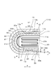
- FIG. 3 is a partially enlarged cross-sectional view of a gas sensor element in Example 1.
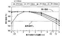
- FIG. 3 is a diagram illustrating a relationship between a position where a heat generating portion is formed and an element temperature in the first embodiment.
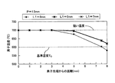
- FIG. 3 is a diagram illustrating a relationship between the length of a heat generating portion and element temperature in Example 1. The figure which shows the relationship between the formation position of a heat-emitting part and sensor output in Example 1.
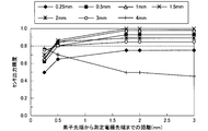
- FIG. The figure which shows the relationship between the formation position of a heat-emitting part and sensor output in Example 1.
- FIG. FIG. 3 is a diagram showing the relationship between the thickness of the diffused resistance layer and the power consumption in Example 1.
- FIG. 3 is a diagram illustrating the relationship between the thickness of the diffusion resistance layer and the sensor output in the first embodiment. The figure which shows the relationship between the porosity of a diffused resistance layer, and a sensor output in Example 1.
- FIG. 9 is a partially enlarged view of a cross section of a gas sensor element in Example 2.
- the gas sensor of the present disclosure can be used for a detection mechanism of a specific gas concentration in exhaust gas of an internal combustion engine provided in an automobile or the like.
- the gas sensor 1 of this example includes a gas sensor element 10.
- the gas sensor element 10 includes a bottomed cylindrical cup-shaped solid electrolyte body 11, a reference electrode 12 formed on an inner surface 11 a of the solid electrolyte body 11, and an outer surface of the solid electrolyte body 11.
- the gas sensor element 10 is configured to output a limit current value depending on a specific gas concentration in the gas to be measured by applying a predetermined voltage between the reference electrode 12 and the measurement electrode 13.
- This is a current type gas sensor element.
- the measurement electrode 13 has a length L2 in the axial direction X of 0.5 mm to 3.0 mm, and extends from the tip of the solid electrolyte body 11 (tip of the outer surface 11b of the solid electrolyte body 11) 11c. It is within the range of 0.5 mm to 7.5 mm in the axial direction X.
- “to” that defines a numerical range means a range including a boundary numerical value.
- the “tip side” is one side in the axial direction X of the gas sensor 1 and refers to the side where the gas sensor 1 is exposed to the gas to be measured.
- the “base end side” refers to the opposite side.
- the solid electrolyte body 11 is made of ceramics mainly composed of zirconia.
- the solid electrolyte body 11 has a bottomed cylindrical cup shape.
- the opening-side end portion of the solid electrolyte body 11 (that is, the upper end portion in FIG. 1) is a base end 11d, and the opposite side of the base end 11d is a front end 11c.
- the tip 11c is curved in a hemispherical shape.
- a heater 20 is provided inside the solid electrolyte body 11.
- the heater 20 includes a rod-shaped ceramic mandrel 21 and a sheet-like heat generating member 22 wound around the peripheral surface of the mandrel 21.
- the tip corner 22 a of the heat generating member 22 is in contact with the curved inner surface 11 a (reference electrode 12) at the tip 11 c of the solid electrolyte body 11.
- the tip corner 22a is located in the range of 1.5 mm to 2.0 mm from the tip 11c in the axial direction X.
- the heat generating member 22 has a heat generating portion 23 that generates heat by energizing the heat generating member 22 on the tip 11c side.
- the length L1 of the heat generating portion 23 in the axial direction X can be set to 3.0 mm to 7.0 mm.
- the heat generating portion 23 is within the range of 0.25 mm to 9.0 mm from the tip 22a of the heater 20 in the axial direction X.
- the heat generating portion 23 is positioned near the tip 22 a of the heater 20, and at least a part (all in this example) of the heat generating portion 23 faces the measurement electrode 13. .
- the reference electrode 12 is formed on a part of the inner peripheral surface 11 a of the solid electrolyte body 11 facing the heat generating portion 23 of the heater 20.
- the reference electrode 12 is formed over the entire circumference in the circumferential direction of the inner peripheral surface 11 a of the solid electrolyte body 11.
- a measurement electrode 13 is formed over substantially the entire outer peripheral surface 11 b of the solid electrolyte body 11. As shown in FIG. 1, the reference electrode 12 and the measurement electrode 13 are respectively connected to lead wires 121 and 131 drawn to the base end 11d side.
- the length L2 of the measuring electrode 13 in the axial direction X is 0.5 mm to 3.0 mm. If the length L2 is shorter than 0.5 mm, the sensor output may be small, and sufficient detection accuracy may not be obtained. On the other hand, when the length L2 is longer than 3.0 mm, variations in temperature at the measurement electrode 13 are likely to occur, and the detection accuracy may be reduced.
- the measurement electrode 13 is within a range of 0.5 mm to 7.5 mm from the tip 11 c of the solid electrolyte body 11.
- the measurement electrode 13 is within the region facing the heat generating portion 23 on the outer surface 11b of the solid electrolyte body 11 (the region indicated by the arrow L1 in FIG. 2).
- a diffusion resistance layer 30 made of a porous body that covers at least the measurement electrode 13 is provided outside the solid electrolyte body 11.
- the diffusion resistance layer 30 covers the entire area outside the solid electrolyte body 11.
- the diffusion resistance layer 30 is formed by applying a ceramic coating to the outside of the solid electrolyte body 11.
- the thickness M1 of the diffusion resistance layer 30 on the measurement electrode 13 can be 400 ⁇ m to 700 ⁇ m, and is preferably 450 ⁇ m to 600 ⁇ m.
- the porosity of the diffusion resistance layer 30 can be 2.0% to 8.0%, and preferably 4.5% to 5.5%. In this example, the porosity of the diffusion resistance layer 30 can be measured by the Archimedes method.
- the diffusion resistance layer 30 is formed so as to straddle the outer side surface of the measurement electrode 13 and the outer side surface 11b of the solid electrolyte body 11.
- the thickness M1 of the diffusion resistance layer 30 on the measurement electrode 13 and the thickness M2 of the diffusion resistance layer 30 on the outer surface 11b of the solid electrolyte body 11 excluding the measurement electrode 13 are M2 / M1 ⁇ 1. 35 relationship is satisfied, and it is preferable to satisfy the relationship of M2 / M1 ⁇ 1.25.
- the thickness M1 of the diffusion resistance layer 30 on the measurement electrode 13 means the distance from the outer surface of the measurement electrode 13 to the outer surface 30a of the diffusion resistance layer 30. It shall be said.
- the “thickness M2 of the diffusion resistance layer 30 on the outer surface 11b of the solid electrolyte body 11 excluding the measurement electrode 13” refers to a region of the outer surface 11b of the solid electrolyte body 11 where the measurement electrode 13 is not formed.
- the distance from the position corresponding to the outer side surface of the measurement electrode 13 to the outer side surface 30a of the diffusion resistance layer 30 is referred to.
- M1 ⁇ M2 and a recess 31 is formed in a portion facing the measurement electrode 13 on the outer surface 30b of the diffusion resistance layer 30.
- a porous protective layer 40 having a higher porosity than the diffusion resistance layer 30 is formed on the outer surface 30 b of the diffusion resistance layer 30.
- the protective layer 40 is provided to trap poisonous components in the measurement gas (exhaust gas).
- the protective layer 40 is a ceramic made of alumina and carries platinum.
- the protective layer 40 is provided so as to cover the entire outer side surface 30 b of the diffusion resistance layer 30.
- the thickness N of the protective layer 40 can be set to a desired thickness.
- the porosity of the protective layer 40 can be 50% to 90%. In this example, the porosity of the protective layer 40 can be measured by the Archimedes method.
- the relationship between the contact position (tip corner 22a) between the heater 20 and the solid electrolyte body 11 and the temperature variation of the outer surface 11b of the solid electrolyte body 11 was verified. Specifically, the length L1 of the heat generating portion 23 of the heater 20 was 3 mm, and the target temperature was 700 ° C. Then, the distance P between the contact position (tip corner 22a) of the heater 20 and the tip 11c is changed at intervals of 0.5 mm in the range of 1.0 mm to 2.5 mm, and the temperature of the outer surface 11b in each case is changed. Measurements were made in the range from the tip 11c to 8.0 mm. The reference temperature T 0 was 600 ° C. at which the difference between the gas species in the adsorption / desorption reaction with respect to the electrode was small, and the variation in the temperature (element temperature) of the outer surface 11b with respect to the target temperature was evaluated.
- the element temperature is equal to or higher than the reference temperature T 0 (600 ° C.) when the distance from the tip 11c of the solid electrolyte body 11 is less than 6.9 mm. It was. On the other hand, when the distance from the tip 11c of the solid electrolyte body 11 is in the range of 6.9 mm to 8.0 mm, the element temperature is lower than the reference temperature T 0 . When P was 1.5 mm, the element temperature was equal to or higher than the reference temperature T 0 when the distance from the tip 11 c of the solid electrolyte body 11 was 7.5 mm or less.
- the element temperature is lower than the reference temperature T 0 in the range where the distance from the tip 11c of the solid electrolyte body 11 is greater than 7.5 mm and equal to or less than 8.0 mm.
- P was 2.0 mm
- the element temperature was higher than the reference temperature T 0 in the range where the distance from the tip 11c of the solid electrolyte body 11 that is the entire measurement range was 8.0 mm or less.
- P was 2.5 mm
- the element temperature was lower than the reference temperature T 0 when the distance from the tip 11 c of the solid electrolyte body 11 was less than 0.24 mm.
- the element temperature was higher than the reference temperature T 0 when the distance from the tip 11c of the solid electrolyte body 11 was in the range of 0.24 to 8.0 mm. That is, under such conditions, in the range where the distance from the tip 11c is 7.5 mm or less, if P is 1.5 mm to 2.0 mm, there is little variation in temperature.
- the relationship between the length L1 of the heat generating portion 23 of the heater 20 and the temperature variation of the outer surface 11b of the solid electrolyte body 11 was verified. Specifically, as shown in FIG. 2, the distance P between the contact position (tip corner 22a) of the heater 20 and the tip 11c is 1.5 mm, and the length L1 of the heat generating portion 23 in the axial direction X is changed. Then, the temperature of the outer surface 11b in each case was measured. Then, it was evaluated based on the reference temperature T 0.
- L1 is preferably 3.0 mm to 7.0 mm.
- the length L1 of the measurement electrode 13 is 0.25 mm, 0.5 mm, 1.0 mm, 1.5 mm, 2.0 mm, 3.0 mm, and 4.0 mm. I prepared something.
- the aim output value IL 0 of the gas sensor element 10 to calculate the deviation percentage (IL 1 / IL 0) for IL 0 of the IL 1 as a sensor output accuracy.
- the sensor output accuracy needs to be 0.8 or more.
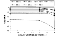
- the length L2 of the measurement electrode 13 is 0.5 mm to 3.0 mm, and the formation position of the measurement electrode 13 is within the range of 0.5 mm to 7.5 mm from the tip 11c.
- the sensor output accuracy is 0.8 or more.
- the formation position of the measurement electrode 13 is in the range of 1.75 mm to 7.0 mm from the tip 11c, it is shown that the sensor output accuracy is substantially unchanged and stable.
- the temperature of the measurement electrode 13 is less than 600 ° C., the difference due to the gas type of the adsorption / desorption reaction with respect to the measurement electrode 13 increases, and the detection accuracy decreases. Therefore, to increase the detection accuracy, the temperature of the measurement electrode 13 is It is preferable that the temperature be 600 ° C or higher.
- the power consumption in the gas sensor 1 of the present example was calculated assuming that the power consumption when the M1 is 300 ⁇ m is 1. If the power consumption ratio exceeds 1.4, there is a concern about the influence on fuel consumption, and therefore the power consumption ratio needs to be 1.4 or less. Moreover, in order to suppress the increase in power consumption, the power consumption ratio needs to be 1.2 or less. As shown in FIG.
- the power consumption ratio is 1.4 or less. Further, it was shown that when the thickness M1 of the diffusion resistance layer 30 on the measurement electrode 13 is 600 ⁇ m or less, the power consumption ratio is 1.2 or less.
- the water resistance is changed to the thickness M1 of the diffusion resistance layer 30 on the measurement electrode 13 of 300 ⁇ m. It was compared with the water resistance at the time. Specifically, the element temperature of the 3 mm portion from the tip of the element is set to 700 ° C., a water droplet is dropped from the tip 11 c to the base end 11 d side at a position of 3 mm, and the amount of water dropped is increased until the gas sensor element 10 is broken. The amount of dropped water droplets at which the cracks occur was defined as water resistance.
- the water resistance when M1 was 300 ⁇ m was set to 1, and the water resistance when M1 was changed between 300 ⁇ m and 800 ⁇ m was calculated.
- the water resistance needs to be 1.6 or more.
- the water resistance needs to be 1.8 or more.
- the thickness M1 of the diffusion resistance layer 30 is 400 ⁇ m or more, the water resistance is 1.6 or more.
- the thickness M1 of the diffusion resistance layer 30 is 450 ⁇ m or more, the water resistance is 1.8 or more.
- the thickness M1 of the diffusion resistance layer 30 on the measurement electrode 13 needs to be in the range indicated by the arrow T in FIG. 7, that is, 400 ⁇ m to 700 ⁇ m. It was. Further, it was shown that the thickness M1 of the diffusion resistance layer 30 on the measurement electrode 13 is preferably in the range indicated by the arrow U in FIG. 7, that is, 450 ⁇ m to 600 ⁇ m.
- the sensor output accuracy (IL / IL m ) needs to be 0.9 or more. As shown in FIG. 8, when M2 / M1 ⁇ 1.35, the sensor output accuracy (IL / IL m ) is 0.8 or more. Further, when M2 / M1 ⁇ 1.25, the sensor output accuracy (IL / IL m ) is 0.9 or more.
- the thickness M1 of the diffusion resistance layer 30 on the measurement electrode 13 and the thickness M2 on the solid electrolyte body 11 excluding the measurement electrode 13 need to satisfy M2 / M1 ⁇ 1.35, and M2 It was confirmed that /M1 ⁇ 1.25 is preferable.
- the sensor output value IL is detected by changing the porosity of the diffusion resistance layer 30 in a range of 1.0% to 14.0%, and the conventional O 2 sensor having a protective layer with a porosity of 5.0% is used.
- the sensor output accuracy (IL / IL 0 ) was calculated based on the sensor output IL 0 . In order to obtain sufficient A / F detection accuracy, the sensor output accuracy needs to be 0.8 or more. As shown in FIG. 9, when the porosity of the diffusion resistance layer 30 is 2.0% to 8.0%, the sensor output accuracy is 0.8 or more. Therefore, it was confirmed that the porosity of the diffusion resistance layer 30 is required to be 2.0% to 8.0%.
- the effect in the gas sensor 1 of this example is explained in full detail.
- the measurement electrode 13 has a length L1 in the axial direction X of 0.5 mm to 3.0 mm and is within a range of 0.5 mm to 7.5 mm from the tip 11c of the solid electrolyte body 11.
- the measurement electrode 13 is formed with a sufficiently short length L1 in the axial direction X, and is provided within a predetermined range from the tip 11c of the solid electrolyte body 11.
- variation in the temperature in the measurement electrode 13 can be suppressed, and the dispersion
- variation in gas adsorption reactivity is reduced in a small amount of gas atmosphere at stoichiometry, and variation in stoichiometric detection performance is suppressed.
- by mounting (rear mounting) on the downstream side of the catalyst of a vehicle having a very small gas atmosphere the A / F can always be detected with high accuracy and can be applied to stoichiometric control.
- the diffusion resistance layer 30 is porous and is formed on the measurement electrode 13, the amount of gas reaction at the measurement electrode 13 can be controlled. Thereby, the detection accuracy of A / F can be improved.
- the thickness M1 of the diffusion resistance layer 30 on the measurement electrode 13 is set to 400 ⁇ m to 700 ⁇ m. As a result, it is possible to achieve both A / F detection accuracy improvement, power consumption reduction, and shortening of the activation time of the solid electrolyte body 11. Furthermore, by setting the thickness M1 of the diffusion resistance layer 30 on the measurement electrode 13 to 450 ⁇ m to 600 ⁇ m, it is possible to more effectively improve the A / F detection accuracy, reduce the power consumption, and shorten the activation time.
- the porosity of the diffusion resistance layer 30 is set to 2.0% to 8.0%.
- the influence namely, temperature characteristic
- the A / F detection accuracy can be improved.
- the porosity of the diffusion resistance layer 30 is set to 4.5% to 5.5%, the temperature characteristics can be further reduced, and the A / F detection accuracy can be further improved.
- the diffusion resistance layer 30 is formed so as to straddle the outer surface of the measurement electrode 13 and the outer surface 11b of the solid electrolyte body 11.
- the thickness M1 of the diffusion resistance layer 30 on the measurement electrode 13 and the thickness M2 on the solid electrolyte body 11 satisfy the relationship of M2 / M1 ⁇ 1.35.
- M2 / M1 ⁇ 1.25 it is possible to further improve the A / F detection accuracy and reduce the thermal stress.
- a protective layer 40 made of a porous material having a higher porosity than the diffusion resistance layer 30 is formed on the outer surface 30 a of the diffusion resistance layer 30.
- the protective layer 40 contains platinum.
- platinum can accelerate
- FIG. it is possible to prevent hydrogen gas from reaching the measurement electrode 13 ahead of other components in the exhaust gas and shifting the sensor output to the rich side. As a result, the A / F detection accuracy can be improved.
- the measurement electrode 13 is within the region facing the heat generating portion 23 on the outer surface 11b of the solid electrolyte body 11 (the region indicated by the arrow L1 in FIG. 2).
- the heat of the heater 20 is transferred from the tip corner 22a to the measurement electrode 13 via the solid electrolyte body 11 and easily reaches the measurement electrode 13 by radiation. It becomes easy to reach the entire 13 uniformly. Thereby, the temperature variation of the measurement electrode 13 can be made smaller. As a result, the A / F detection accuracy can be improved.
- the tip corner 22a that contacts the inner surface 11a of the solid electrolyte body 11 in the heater 20 is located in the range of 1.5 mm to 2.0 mm from the tip 11c of the solid electrolyte body 11 in the axial direction X. .
- the length L1 of the heat generating portion 23 of the heater 20 is 3.0 mm to 7.0 mm, and the heat generating portion 23 is within 0.25 mm to 9.0 mm from the tip 22a of the heater 20 in the axial direction X. Is in the range.
- the heat generating part 23 is arranged on the side close to the tip 22a that is the contact position between the solid electrolyte body 11 and the heater 20, and at least a part (all in this example) of the heat generating part 23 is placed on the measurement electrode 13. It will be opposite. Therefore, the heat generated from the heat generating portion 23 can be efficiently propagated to the measurement electrode 13 via the tip 22a of the heater 20, and thus the temperature variation of the measurement electrode 13 can be further reduced. As a result, it is possible to further improve the A / F detection accuracy.
- the gas sensor element 10 that is excellent in rapid thermal performance and can detect A / F with high accuracy.
- symbol is attached
Landscapes
- Chemical & Material Sciences (AREA)
- Life Sciences & Earth Sciences (AREA)
- Health & Medical Sciences (AREA)
- Physics & Mathematics (AREA)
- Chemical Kinetics & Catalysis (AREA)
- Electrochemistry (AREA)
- Molecular Biology (AREA)
- Analytical Chemistry (AREA)
- Biochemistry (AREA)
- General Health & Medical Sciences (AREA)
- General Physics & Mathematics (AREA)
- Immunology (AREA)
- Pathology (AREA)
- Measuring Oxygen Concentration In Cells (AREA)
Abstract
速熱性に優れ、A/Fを高精度に検出することができ、ストイキを高精度に検出できるガスセンサを提供する。ガスセンサ(1)は、限界電流式のガスセンサ素子(10)を有する。ガスセンサ素子(10)は、コップ型の固体電解質体(11)と、固体電解質体(11)の内側面(11a)に形成された基準電極(12)と、固体電解質(11)の外側面(11b)に形成された測定電極(13)と、ヒータ(20)とを有する。ヒータ(20)は先端が固体電解質体(11)の内側面(11a)に接するように固体電解質体(11)の内側に配置されている。ガスセンサ(1)は、基準電極(12)と測定電極(13)との間に所定の電圧を印加することにより、排ガス中の酸素濃度に依存した限界電流値を出力する。測定電極(13)は軸方向Xの長さが0.5mm~3.0mmであり、固体電解質体(11)の先端(11c)から軸方向Xにおいて0.5mm~7.5mmの範囲に収まっている。
Description
本出願は、2014年6月30日にされた日本出願番号2014-133486号、及び2015年2月12日にされた日本出願番号2015-25182号に基づくもので、ここにその記載内容を援用する。
本発明は、ガスセンサに関する。
従来、内燃機関などから排出される排気ガス中に含まれる酸素濃度を検出して、空燃比(A/F)の制御に利用するためのガスセンサがある。例えば、特許文献1には、いわゆるコップ型の固体電解質体と、固体電解質体の内側面に設けられた基準電極と、ガスセンサ素子の外側面に設けられた測定電極とを、固体電解質体の内側に配設されたヒータと、を有するガスセンサ素子を内蔵するガスセンサが開示されている。このガスセンサは、固体電解質体がヒータにより加熱されて活性化された状態で使用される。
近年、内燃機関において、触媒貴金属の使用量の削減と排ガスの浄化効率向上が更に求められている。特に触媒による浄化能力が高いストイキに制御することが求められている。そして、排気ガスの浄化効率を高めるには、内燃機関の始動直後からストイキでの微量のガス雰囲気下(ppmオーダー)も含め、高精度にA/Fを検出することが必要となる。しかしながら、上述の如く、ガスセンサは、ガスセンサ素子の固体電解質体が加熱により活性化された状態で使用する必要があるため、内燃機関の始動直後においてガスセンサ素子が十分に加熱されていないと、始動直後のA/Fを高精度に検出することが困難となる。また、ガスセンサ素子の検知部(すなわち、測定電極や基準電極)内に温度のばらつきがあると検出性能にもばらつきが生じて、A/Fを正確に検出できない。特にストイキでの微量のガス雰囲気下ではガス吸着反応性のばらつきによって、ストイキが検出できない。そのため、従来は、ヒータの輻射熱を利用してガスセンサ素子を加熱することにより検知部の均熱性を確保して、検出性能(ガス吸着反応性)のばらつきを抑制している。しかしながら、輻射熱を利用しているため、速熱性に劣り、ガスセンサ素子の活性温度に昇温するのに時間が要することから、かかる観点からも始動直後のA/Fを高精度に検出すること、及びストイキを高精度に検出することは困難である。
本開示は、かかる背景に鑑みてなされたもので、速熱性に優れ、A/Fを高精度に検出することができ、特にストイキを高精度に検出できるガスセンサを提供しようとするものである。
本開示の一態様は、有底筒状のコップ型の固体電解質体と、
該固体電解質体の内側面に形成された基準電極と、
上記固体電解質体の外側面に形成された測定電極と、
先端が上記固体電解質体の内側面に接するように上記固体電解質体の内側に配置されるとともに、上記固体電解質体を加熱する発熱部を有するヒータと、
を備え、
上記基準電極と上記測定電極との間に所定の電圧を印加することにより、被測定ガス中の特定ガス濃度に依存した限界電流値を出力するように構成された限界電流式のガスセンサ素子を有するガスセンサであって、
上記測定電極は、軸方向の長さが0.5mm~3.0mmであるとともに、上記固体電解質体の先端から軸方向において0.5mm~7.5mmの範囲に収まっているガスセンサにある。
該固体電解質体の内側面に形成された基準電極と、
上記固体電解質体の外側面に形成された測定電極と、
先端が上記固体電解質体の内側面に接するように上記固体電解質体の内側に配置されるとともに、上記固体電解質体を加熱する発熱部を有するヒータと、
を備え、
上記基準電極と上記測定電極との間に所定の電圧を印加することにより、被測定ガス中の特定ガス濃度に依存した限界電流値を出力するように構成された限界電流式のガスセンサ素子を有するガスセンサであって、
上記測定電極は、軸方向の長さが0.5mm~3.0mmであるとともに、上記固体電解質体の先端から軸方向において0.5mm~7.5mmの範囲に収まっているガスセンサにある。
上記ガスセンサにおいては、ヒータは固体電解質体の内側面に接しているためヒータから固体電解質体への熱伝導が促され、固体電解質体の速熱性が向上する。さらに、測定電極は、軸方向における長さが0.5mm~3.0mmであるとともに、固体電解質体の先端から0.5mm~7.5mmの範囲に収まっている。すなわち、測定電極は軸方向における長さが十分に短く形成されており、固体電解質体の先端から所定の範囲内に設けられている。これにより、測定電極内の温度のばらつきを抑制でき、測定電極内における検出性能のばらつきが抑制される。特にストイキでの微量のガス雰囲気下ではガス吸着反応性のばらつきが低減され、ストイキ検出性能のばらつきが抑制される。これらの結果、ストイキでの微量のガス雰囲気下(ppmオーダー)も含め、始動直後のA/Fを高精度に検出することができる。また、微量のガス雰囲気となる車両の触媒下流に搭載(リア搭載)することによって、常にA/Fを高精度に検出でき、ストイキ制御に適用できる。
以上のごとく、本発明によれば、速熱性に優れ、A/Fを高精度に検出することができ、特にストイキを高精度に検出できるガスセンサを提供することができる。
本開示のガスセンサは、自動車等に備えられる内燃機関の排ガス等における特定ガス濃度の検出機構に使用することができる。
(実施例1)
実施例に係るガスセンサにつき、図1~図9を用いて説明する。
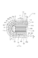
本例のガスセンサ1は、ガスセンサ素子10を有する。ガスセンサ素子10は、図1に示すように、有底筒状のコップ型の固体電解質体11と、固体電解質体11の内側面11aに形成された基準電極12と、固体電解質体11の外側面11bに形成された測定電極13と、先端22aが固体電解質体11の内側面11aに接するように固体電解質体11の内側に配置されるとともに、固体電解質体11を加熱する発熱部23を有するヒータ20と、を備える。
実施例に係るガスセンサにつき、図1~図9を用いて説明する。
本例のガスセンサ1は、ガスセンサ素子10を有する。ガスセンサ素子10は、図1に示すように、有底筒状のコップ型の固体電解質体11と、固体電解質体11の内側面11aに形成された基準電極12と、固体電解質体11の外側面11bに形成された測定電極13と、先端22aが固体電解質体11の内側面11aに接するように固体電解質体11の内側に配置されるとともに、固体電解質体11を加熱する発熱部23を有するヒータ20と、を備える。
そして、ガスセンサ素子10は、基準電極12と測定電極13との間に所定の電圧を印加することにより、被測定ガス中の特定ガス濃度に依存した限界電流値を出力するように構成された限界電流式のガスセンサ素子である。図2に示すように、測定電極13は、軸方向Xにおける長さL2が0.5mm~3.0mmであり、固体電解質体11の先端(固体電解質体11の外側面11bの先端)11cから軸方向Xにおいて0.5mm~7.5mmの範囲に収まっている。なお、本開示において、特に規定しない限り数値範囲を定める「~」は、境界の数値を含む範囲を意味する。
図1に示すごとく、本例において、「先端側」とは、ガスセンサ1の軸方向Xの一方側であり、ガスセンサ1が被測定ガスに晒される側をいう。また、「基端側」とは、その反対側をいう。
以下、本例のガスセンサ1について、詳述する。
固体電解質体11はジルコニアを主成分とするセラミックスからなる。固体電解質体11は有底筒状のコップ型を成している。固体電解質体11の軸方向(長手方向)をXとする。軸方向Xにおいて、固体電解質体11の開口側端部(すなわち、図1における紙面上方端部)を基端11dとし、基端11dの反対側を先端11cとする。図2に示すように、先端11cは半球面状に湾曲している。
固体電解質体11はジルコニアを主成分とするセラミックスからなる。固体電解質体11は有底筒状のコップ型を成している。固体電解質体11の軸方向(長手方向)をXとする。軸方向Xにおいて、固体電解質体11の開口側端部(すなわち、図1における紙面上方端部)を基端11dとし、基端11dの反対側を先端11cとする。図2に示すように、先端11cは半球面状に湾曲している。
固体電解質体11の内側には、ヒータ20が設けられている。ヒータ20は棒状のセラミックスの心棒21と、心棒21の周面に巻き付けられたシート状の発熱部材22とを備える。発熱部材22の先端隅部22aは固体電解質体11の先端11cにおける湾曲した内側面11a(基準電極12)に接している。先端隅部22aは、軸方向Xにおいて先端11cから1.5mm~2.0mmの範囲に位置している。
発熱部材22は、図2に示すように、先端11c側に発熱部材22への通電によって発熱する発熱部23を有している。軸方向Xにおける発熱部23の長さL1は、3.0mm~7.0mmとすることができる。発熱部23は軸方向Xにおいて、ヒータ20の先端22aから0.25mm~9.0mmの範囲に収まっている。これにより、図2に示すように、発熱部23はヒータ20の先端22aに近い位置に位置するとともに、発熱部23の少なくとも一部(本例では全部)が測定電極13に対向することとなる。
固体電解質体11の内周面11aの内、ヒータ20の発熱部23と対向する部分の一部には基準電極12が形成されている。基準電極12は、固体電解質体11の内周面11aの周方向において全周に亘って形成されている。固体電解質体11の外周面11bの略全域には測定電極13が形成されている。図1に示すように、基準電極12及び測定電極13はそれぞれ、基端11d側に引き出されたリード線121、131に接続されている。
図2に示すように、測定電極13の軸方向Xにおける長さL2は0.5mm~3.0mmである。長さL2が0.5mmよりも短い場合には、センサ出力が小さくなり検出精度が十分に得られないおそれがある。一方、長さL2が3.0mmよりも長い場合には、測定電極13における温度のばらつきが生じやすくなるため、検出精度が低下するおそれがある。
図2に示すように、測定電極13は、固体電解質体11の先端11cから0.5mm~7.5mmの範囲に収まっている。そして、本例では、測定電極13は固体電解質体11の外側面11bにおける発熱部23に対向している領域内(図2において矢印L1で示す領域)に収まっている。
図2に示すように、固体電解質体11の外側には少なくとも測定電極13を覆う多孔質体からなる拡散抵抗層30が設けられている。本例では、拡散抵抗層30は固体電解質体11の外側の全域を覆っている。拡散抵抗層30は固体電解質体11の外側にセラミックコーティングを施すことによって形成されている。拡散抵抗層30の測定電極13上における厚さM1は、400μm~700μmとすることができ、中でも450μm~600μmであることが好ましい。
拡散抵抗層30の気孔率は、2.0%~8.0%とすることができ、4.5%~5.5%であることが好ましい。なお、本例では、拡散抵抗層30の気孔率は、アルキメデス法により測定することができる。
図2に示すように、拡散抵抗層30は測定電極13の外側面と、固体電解質体11の外側面11bとに跨るように形成されている。そして、拡散抵抗層30の測定電極13上における厚さM1と、測定電極13上を除く固体電解質体11の外側面11b上における拡散抵抗層30の厚さM2とは、M2/M1≦1.35の関係を満たしており、M2/M1≦1.25の関係を満たすことが好ましい。なお、図2に示すように、本明細書では、「拡散抵抗層30の測定電極13上における厚さM1」とは、測定電極13の外側面から拡散抵抗層30の外側面30aまでの距離をいうものとする。また、「測定電極13上を除く固体電解質体11の外側面11b上における拡散抵抗層30の厚さM2」とは、固体電解質体11の外側面11bのうち測定電極13が形成されていない領域における測定電極13の外側面に相当する位置から拡散抵抗層30の外側面30aまでの距離をいうものとする。本例では、M1<M2となっており、拡散抵抗層30の外側面30bにおいて測定電極13に対向する部分には凹部31が形成されている。
図2に示すように、拡散抵抗層30の外側面30bには、拡散抵抗層30よりも気孔率が高い多孔質の保護層40が形成されている。保護層40は、被測定ガス(排ガス)中の被毒成分をトラップするために設けられている。保護層40はアルミナからなるセラミックスであり、白金が担持されている。本例では、保護層40は拡散抵抗層30の外側面30bの全体を覆うように設けられている。保護層40の厚さNは、所望の厚さに設定することができる。保護層40の気孔率は50%~90%とすることができる。なお、本例では、保護層40の気孔率はアルキメデス法により測定することができる。
(温度ばらつき評価)
ヒータ20と固体電解質体11との接触位置(先端隅部22a)と固体電解質体11の外側面11bの温度のばらつきの関係を検証した。具体的には、ヒータ20の発熱部23の長さL1を3mmとして、狙い温度を700℃とした。そして、ヒータ20の接触位置(先端隅部22a)と先端11cとの距離Pを1.0mm~2.5mmの範囲において0.5mm間隔で変更して、それぞれの場合の外側面11bの温度を先端11cから8.0mmまでの範囲で測定した。電極に対する吸脱着反応のガス種による差が小さくなる600℃を基準温度T0とし、狙い温度に対する外側面11bの温度(素子温度)のばらつきを評価した。
ヒータ20と固体電解質体11との接触位置(先端隅部22a)と固体電解質体11の外側面11bの温度のばらつきの関係を検証した。具体的には、ヒータ20の発熱部23の長さL1を3mmとして、狙い温度を700℃とした。そして、ヒータ20の接触位置(先端隅部22a)と先端11cとの距離Pを1.0mm~2.5mmの範囲において0.5mm間隔で変更して、それぞれの場合の外側面11bの温度を先端11cから8.0mmまでの範囲で測定した。電極に対する吸脱着反応のガス種による差が小さくなる600℃を基準温度T0とし、狙い温度に対する外側面11bの温度(素子温度)のばらつきを評価した。
図3に示すように、Pが1.0mmである場合には、固体電解質体11の先端11cからの距離が6.9mm未満の範囲では、素子温度が基準温度T0(600℃)以上となっていた。一方、固体電解質体11の先端11cからの距離が6.9mm~8.0mmの範囲では、素子温度が基準温度T0よりも低くなっていた。
Pが1.5mmである場合には、固体電解質体11の先端11cからの距離が7.5mm以下の範囲では、素子温度が基準温度T0以上となっていた。一方、固体電解質体11の先端11cからの距離が7.5mmより大きく8.0mm以下の範囲では、素子温度が基準温度T0よりも低くなっていた。
Pが2.0mmである場合には、測定範囲全域である固体電解質体11の先端11cからの距離が8.0mm以下の範囲において、素子温度が基準温度T0よりも高くなっていた。
Pが2.5mmである場合には、固体電解質体11の先端11cからの距離が0.24mm未満の範囲では素子温度が基準温度T0よりも低くなっていた。一方、固体電解質体11の先端11cからの距離が0.24~8.0mmの範囲では、素子温度が基準温度T0よりも高くなっていた。
すなわち、かかる条件下において、先端11cからの距離が7.5mm以下の範囲では、Pが1.5mm~2.0mmであれば、温度のばらつきが少ないことが示された。
Pが1.5mmである場合には、固体電解質体11の先端11cからの距離が7.5mm以下の範囲では、素子温度が基準温度T0以上となっていた。一方、固体電解質体11の先端11cからの距離が7.5mmより大きく8.0mm以下の範囲では、素子温度が基準温度T0よりも低くなっていた。
Pが2.0mmである場合には、測定範囲全域である固体電解質体11の先端11cからの距離が8.0mm以下の範囲において、素子温度が基準温度T0よりも高くなっていた。
Pが2.5mmである場合には、固体電解質体11の先端11cからの距離が0.24mm未満の範囲では素子温度が基準温度T0よりも低くなっていた。一方、固体電解質体11の先端11cからの距離が0.24~8.0mmの範囲では、素子温度が基準温度T0よりも高くなっていた。
すなわち、かかる条件下において、先端11cからの距離が7.5mm以下の範囲では、Pが1.5mm~2.0mmであれば、温度のばらつきが少ないことが示された。
次に、ヒータ20の発熱部23の長さL1と、固体電解質体11の外側面11bの温度のばらつきとの関係を検証した。具体的には、図2に示すように、ヒータ20の接触位置(先端隅部22a)と先端11cとの距離Pを1.5mmとし、発熱部23の軸方向Xの長さL1を変更して、それぞれの場合の外側面11bの温度を測定した。そして、上記基準温度T0を基準に評価した。
図4に示すように、先端11cから7.5mmまでの範囲内では、L1がいずれの場合でも、上記先端部分及び上記基端部分の両方で基準温度T0以上となっていた。さらに、L1が5.0mm及び7.0mmである場合には両者間に温度ばらつきに変化はなかった。すなわち、かかる条件下では、L1≧3.0mmにおいて、温度のばらつきが少ないことが示された。また、先端11cから7.5mmまでの範囲内では、L1が7.0mm以上になると温度ばらつきに変化は少ないが、発熱部23が過剰に長くなるとヒータ20の消費電力が無駄に増すこととなるため、L1は3.0mm~7.0mmであることが好ましい。
(センサ出力評価)
ガスセンサ1におけるセンサ出力と測定電極13の長さL2及び形成位置との関係を評価した。具体的には、図5に示すように、まず、測定電極13の長さL1が0.25mm、0.5mm、1.0mm、1.5mm、2.0mm、3.0mm及び4.0mmであるものを用意した。各測定電極13の先端部(測定電極先端)13a及び基端部(測定電極基端)13bについて、先端11cからの距離を変更して、センサ出力値IL1を測定した。そして、ガスセンサ素子10の狙い出力値IL0として、各IL1のIL0に対するズレ割合(IL1/IL0)をセンサ出力精度として算出した。十分なA/F検出精度を得るには、センサ出力精度は0.8以上であることを要する。図5及び図6に示すように、測定電極13の長さL2が0.5mm~3.0mmであって、測定電極13の形成位置が先端11cから0.5mm~7.5mmの範囲であれば、センサ出力精度が0.8以上となることが示された。さらに、測定電極13の形成位置が先端11cから1.75mm~7.0mmの範囲であれば、センサ出力精度は実質的に変化がなく、安定していることが示された。そして、測定電極13の温度が600℃未満になると、測定電極13に対する吸脱着反応のガス種による差が大きくなり、検出精度が低下するため、検出精度をより高めるには測定電極13の温度は600℃以上とすることが好ましい。
ガスセンサ1におけるセンサ出力と測定電極13の長さL2及び形成位置との関係を評価した。具体的には、図5に示すように、まず、測定電極13の長さL1が0.25mm、0.5mm、1.0mm、1.5mm、2.0mm、3.0mm及び4.0mmであるものを用意した。各測定電極13の先端部(測定電極先端)13a及び基端部(測定電極基端)13bについて、先端11cからの距離を変更して、センサ出力値IL1を測定した。そして、ガスセンサ素子10の狙い出力値IL0として、各IL1のIL0に対するズレ割合(IL1/IL0)をセンサ出力精度として算出した。十分なA/F検出精度を得るには、センサ出力精度は0.8以上であることを要する。図5及び図6に示すように、測定電極13の長さL2が0.5mm~3.0mmであって、測定電極13の形成位置が先端11cから0.5mm~7.5mmの範囲であれば、センサ出力精度が0.8以上となることが示された。さらに、測定電極13の形成位置が先端11cから1.75mm~7.0mmの範囲であれば、センサ出力精度は実質的に変化がなく、安定していることが示された。そして、測定電極13の温度が600℃未満になると、測定電極13に対する吸脱着反応のガス種による差が大きくなり、検出精度が低下するため、検出精度をより高めるには測定電極13の温度は600℃以上とすることが好ましい。
(拡散抵抗層の厚さ評価)
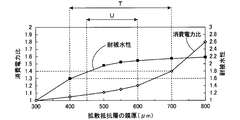
ガスセンサ1において、拡散抵抗層30の測定電極13上における厚さM1を300μm~800μmの間で変更したときの消費電力を、拡散抵抗層30の測定電極13上における厚さM1を300μmとしたときの消費電力と比較した。具体的には、走行モードLA#4における消費電力について、上記M1が300μmであるときの消費電力を1として、本例のガスセンサ1における消費電力比を算出した。上記消費電力比が1.4を超えると燃費への影響が懸念されるため、上記消費電力比は1.4以下であることを要する。また、消費電力の増加を抑制するには、上記消費電力比は1.2以下であることを要する。図7に示すように、拡散抵抗層30の測定電極13上における厚さM1が700μm以下であれば、消費電力比が1.4以下となることが示された。また、拡散抵抗層30の測定電極13上における厚さM1が600μm以下であれば、消費電力比が1.2以下となることが示された。
ガスセンサ1において、拡散抵抗層30の測定電極13上における厚さM1を300μm~800μmの間で変更したときの消費電力を、拡散抵抗層30の測定電極13上における厚さM1を300μmとしたときの消費電力と比較した。具体的には、走行モードLA#4における消費電力について、上記M1が300μmであるときの消費電力を1として、本例のガスセンサ1における消費電力比を算出した。上記消費電力比が1.4を超えると燃費への影響が懸念されるため、上記消費電力比は1.4以下であることを要する。また、消費電力の増加を抑制するには、上記消費電力比は1.2以下であることを要する。図7に示すように、拡散抵抗層30の測定電極13上における厚さM1が700μm以下であれば、消費電力比が1.4以下となることが示された。また、拡散抵抗層30の測定電極13上における厚さM1が600μm以下であれば、消費電力比が1.2以下となることが示された。
さらに、ガスセンサ1において、拡散抵抗層30の測定電極13上における厚さM1を300μm~800μmの間で変更したときの耐被水性を、拡散抵抗層30の測定電極13上における厚さM1を300μmとしたときの耐被水性と比較した。具体的には、素子先端から3mm部の素子温度を700℃にし、先端11cから基端11d側へ3mmの位置に水滴を落とし、ガスセンサ素子10に割れが生じるまで滴下する水滴量を増やしていき、当該割れが生じる滴下水滴量を耐被水性とした。上記M1を300μmとしたときの耐被水性を1として、M1を300μm~800μmの間で変更したときの耐被水性を算出した。リア環境での使用に耐えうるには、当該耐被水性は1.6以上であることを要する。さらに、リア環境での使用において十分な信頼性を得るには、当該耐被水性は1.8以上であることを要する。図7に示すように、拡散抵抗層30の厚さM1が400μm以上であれば、当該耐被水性が1.6以上となることが示された。また、拡散抵抗層30の厚さM1が450μm以上であれば、当該耐被水性が1.8以上となることが示された。
以上の消費電力比及び耐被水性の評価から、拡散抵抗層30の測定電極13上における厚さM1は図7において矢印Tで示す範囲、すなわち、400μm~700μmであることを要することが確認された。さらに、拡散抵抗層30の測定電極13上における厚さM1は図7において矢印Uで示す範囲、すなわち、450μm~600μmであることが好ましいことが示された。
(拡散抵抗層の厚さの評価)
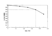
拡散抵抗層30の測定電極13上における厚さM1と測定電極13上を除く固体電解質体11上における厚さM2と、センサ出力精度の関係を評価した。具体的には、M1とM2とが同じとき、すなわち、M2/M1=1となるときのセンサ出力値ILmを1として、M2/M1の値を変更してセンサ出力値ILを検出してセンサ出力精度(IL/ILm)を算出した。図8に示すように、充分なA/F検出精度を得るには、当該センサ出力精度(IL/ILm)は0.8以上であることを要する。また、更に高いA/F検出精度を得るには、当該センサ出力精度(IL/ILm)は0.9以上であることを要する。図8に示すように、M2/M1≦1.35であれば、該センサ出力精度(IL/ILm)は0.8以上となることが示された。また、M2/M1≦1.25であれば、該センサ出力精度(IL/ILm)は0.9以上となることが示された。
拡散抵抗層30の測定電極13上における厚さM1と測定電極13上を除く固体電解質体11上における厚さM2と、センサ出力精度の関係を評価した。具体的には、M1とM2とが同じとき、すなわち、M2/M1=1となるときのセンサ出力値ILmを1として、M2/M1の値を変更してセンサ出力値ILを検出してセンサ出力精度(IL/ILm)を算出した。図8に示すように、充分なA/F検出精度を得るには、当該センサ出力精度(IL/ILm)は0.8以上であることを要する。また、更に高いA/F検出精度を得るには、当該センサ出力精度(IL/ILm)は0.9以上であることを要する。図8に示すように、M2/M1≦1.35であれば、該センサ出力精度(IL/ILm)は0.8以上となることが示された。また、M2/M1≦1.25であれば、該センサ出力精度(IL/ILm)は0.9以上となることが示された。
以上から、拡散抵抗層30の測定電極13上における厚さM1と測定電極13上を除く固体電解質体11上における厚さM2とは、M2/M1≦1.35であることを要し、M2/M1≦1.25であることが好ましいことが確認された。
(拡散抵抗層の気孔率の評価)
次に、拡散抵抗層30の気孔率とセンサ出力精度について評価した。拡散抵抗層30の気孔率を1.0%~14.0%の範囲で変化させてセンサ出力値ILを検出し、従来品である気孔率5.0%の保護層を有するO2センサのセンサ出力IL0を基準として、センサ出力精度(IL/IL0)を算出した。充分なA/F検出精度を得るためには、上記センサ出力精度は0.8以上であることを要する。図9に示すように、拡散抵抗層30の気孔率が2.0%~8.0%であれば、上記センサ出力精度は0.8以上となることが示された。よって、拡散抵抗層30の気孔率が2.0%~8.0%であることを要することが確認された。
次に、拡散抵抗層30の気孔率とセンサ出力精度について評価した。拡散抵抗層30の気孔率を1.0%~14.0%の範囲で変化させてセンサ出力値ILを検出し、従来品である気孔率5.0%の保護層を有するO2センサのセンサ出力IL0を基準として、センサ出力精度(IL/IL0)を算出した。充分なA/F検出精度を得るためには、上記センサ出力精度は0.8以上であることを要する。図9に示すように、拡散抵抗層30の気孔率が2.0%~8.0%であれば、上記センサ出力精度は0.8以上となることが示された。よって、拡散抵抗層30の気孔率が2.0%~8.0%であることを要することが確認された。
次に、本例のガスセンサ1における作用効果について、詳述する。
本例のガスセンサ素子10においては、ヒータ20は固体電解質体11の内側面11aに接しているためヒータ20から固体電解質体11への熱伝導が促され、固体電解質体11の速熱性が向上する。さらに、測定電極13は、軸方向Xにおける長さL1が0.5mm~3.0mmであるとともに、固体電解質体11の先端11cから0.5mm~7.5mmの範囲に収まっている。すなわち、測定電極13は軸方向Xにおける長さL1が十分に短く形成されており、固体電解質体11の先端11cから所定の範囲内に設けられている。これにより、測定電極13内の温度のばらつきを抑制でき、測定電極13内における検出性能のばらつきが抑制される。特にストイキでの微量のガス雰囲気下ではガス吸着反応性ばらつきが低減され、ストイキ検出性能ばらつきが抑制される。これらの結果、ストイキでの微量のガス雰囲気下(ppmオーダー)も含め、始動直後のA/Fを高精度に検出することができる。また、微量のガス雰囲気となる車両の触媒下流に搭載(リア搭載)することによって、常にA/Fを高精度に検出でき、ストイキ制御に適用できる。
本例のガスセンサ素子10においては、ヒータ20は固体電解質体11の内側面11aに接しているためヒータ20から固体電解質体11への熱伝導が促され、固体電解質体11の速熱性が向上する。さらに、測定電極13は、軸方向Xにおける長さL1が0.5mm~3.0mmであるとともに、固体電解質体11の先端11cから0.5mm~7.5mmの範囲に収まっている。すなわち、測定電極13は軸方向Xにおける長さL1が十分に短く形成されており、固体電解質体11の先端11cから所定の範囲内に設けられている。これにより、測定電極13内の温度のばらつきを抑制でき、測定電極13内における検出性能のばらつきが抑制される。特にストイキでの微量のガス雰囲気下ではガス吸着反応性ばらつきが低減され、ストイキ検出性能ばらつきが抑制される。これらの結果、ストイキでの微量のガス雰囲気下(ppmオーダー)も含め、始動直後のA/Fを高精度に検出することができる。また、微量のガス雰囲気となる車両の触媒下流に搭載(リア搭載)することによって、常にA/Fを高精度に検出でき、ストイキ制御に適用できる。
また、拡散抵抗層30は多孔質であって、測定電極13上に形成されているため、測定電極13でのガス反応量を制御できる。これにより、A/Fの検出精度の向上を図ることができる。
また、本例のガスセンサ1では、拡散抵抗層30の測定電極13上における厚さM1を400μm~700μmとしている。これにより、A/Fの検出精度向上と消費電力低減及び固体電解質体11の活性時間の短縮化の両立を図ることができる。さらに、拡散抵抗層30の測定電極13上における厚さM1を450μm~600μmとすることにより、より効果的にA/Fの検出精度向上と消費電力低減および活性時間の短縮化を両立できる。
また本例では、拡散抵抗層30の気孔率を2.0%~8.0%としている。これにより、温度変化がA/F検出精度に与える影響(すなわち、温度特性)を低減することができる。その結果、A/Fの検出精度を向上できる。さらに、拡散抵抗層30の気孔率を4.5%~5.5%とすることにより、より温度特性を低減することができ、A/Fの検出精度を一層向上できる。
また、本例では、拡散抵抗層30は測定電極13の外側面と、固体電解質体11の外側面11bとに跨るように形成されている。そして、拡散抵抗層30の測定電極13上における厚さM1と固体電解質体11上における厚さM2とがM2/M1≦1.35の関係を満たす。これにより、A/Fの検出精度の向上を図ることができるとともに、センサ素子内における熱応力の低減を図ることができる。さらに、本例では、M2/M1≦1.25とすることにより、A/Fの検出精度の向上と上記熱応力の低減との両立が一層図られる。
また、本例では、拡散抵抗層30の外側面30aには、拡散抵抗層30よりも気孔率の高い多孔質からなる保護層40が形成されている。これにより、被毒物によるセンサ特性低下を防止することができる。その結果、A/Fの検出精度の向上を図ることができる。
また、本例では、保護層40は白金を含んでいる。これにより、白金が触媒として水素ガスの燃焼を促進して、水素ガスが測定電極13に到達することを抑制することができる。その結果、水素ガスが排ガス中の他の成分よりも先行して測定電極13に到達してセンサ出力がリッチ側にシフトすることを抑制することができる。その結果、A/Fの検出精度の向上を図ることができる。
本例では、測定電極13は、固体電解質体11の外側面11bにおける発熱部23に対向している領域内(図2において矢印L1で示す領域)に収まっている。これにより、ヒータ20の熱は、先端隅部22aから固体電解質体11を介して測定電極13に伝熱されるとともに、輻射によっても測定電極13に到達しやすくなるため、ヒータ20の熱が測定電極13全体に均一に到達しやすくなる。これにより、測定電極13の温度ばらつきをより小さくすることが出来る。その結果、A/Fの検出精度の向上を図ることができる。
本例では、ヒータ20における固体電解質体11の内側面11aと接触する先端隅部22aは、軸方向Xにおいて固体電解質体11の先端11cから1.5mm~2.0mmの範囲に位置している。これにより、ヒータ20の熱は、先端隅部22aから固体電解質体11を介して測定電極13に伝熱しやすくなるため、測定電極13の温度ばらつきをより小さくすることが出来る。その結果、A/Fの検出精度の向上を図ることができる。
また、本例では、ヒータ20の発熱部23の長さL1が3.0mm~7.0mmであり、発熱部23は軸方向Xにおいてはヒータ20の先端22aから0.25mm~9.0mm内に収まっている。これにより、発熱部23が、固体電解質体11とヒータ20との接触位置である先端22aに近い側に配置されるとともに、発熱部23の少なくとも一部(本例では全部)が測定電極13に対向することとなる。そのため、発熱部23から生じた熱をヒータ20の先端22aを介して測定電極13へ効率的に伝播することができることから、測定電極13の温度ばらつきをさらに小さくすることができる。その結果、A/Fの検出精度のさらなる向上を図ることができる。
以上のごとく、本例によれば、速熱性に優れ、A/Fを高精度に検出することができるガスセンサ素子10を提供することができる。
(実施例2)
本例のガスセンサ1は、図10に示すように、実施例1の凹部31(図2参照)が形成されておらず、M2/M1=1となるように拡散抵抗層30が形成されている。すなわち、拡散抵抗層30の外側面30b及び保護層40の外側面において、測定電極13に対向する部分とそれ以外の部分とがそれぞれ面一となっている。なお、実施例1と同等の構成要素には、同一の符号を付してその説明を省略する。
本例においても、M2/M1≦1.35を満たすため、実施例1の場合と同等の作用効果を奏する。
本例のガスセンサ1は、図10に示すように、実施例1の凹部31(図2参照)が形成されておらず、M2/M1=1となるように拡散抵抗層30が形成されている。すなわち、拡散抵抗層30の外側面30b及び保護層40の外側面において、測定電極13に対向する部分とそれ以外の部分とがそれぞれ面一となっている。なお、実施例1と同等の構成要素には、同一の符号を付してその説明を省略する。
本例においても、M2/M1≦1.35を満たすため、実施例1の場合と同等の作用効果を奏する。
1 ガスセンサ
10 ガスセンサ素子
11 固体電解質体
12 基準電極
13 測定電極
20 ヒータ
22 発熱部材
23 発熱部
30 拡散抵抗層
40 保護層
10 ガスセンサ素子
11 固体電解質体
12 基準電極
13 測定電極
20 ヒータ
22 発熱部材
23 発熱部
30 拡散抵抗層
40 保護層
Claims (13)
- 有底筒状のコップ型の固体電解質体(11)と、
該固体電解質体(11)の内側面(11a)に形成された基準電極(12)と、
上記固体電解質体(11)の外側面(11b)に形成された測定電極(13)と、
先端(22a)が上記固体電解質体(11)の内側面(11a)に接するように上記固体電解質体(11)の内側に配置されるとともに、上記固体電解質体(11)を加熱する発熱部(23)を有するヒータ(20)と、
を備え、
上記基準電極(12)と上記測定電極(13)との間に所定の電圧を印加することにより、被測定ガス中の特定ガス濃度に依存した限界電流値を出力するように構成された限界電流式のガスセンサ素子(10)を有するガスセンサ(1)であって、
上記測定電極(13)は、軸方向(X)の長さが0.5mm~3.0mmであるとともに、上記固体電解質体(11)の先端(11c)から軸方向(X)において0.5mm~7.5mmの範囲に収まっていることを特徴とするガスセンサ(1)。 - 上記固体電解質体(11)の外側には少なくとも上記測定電極(13)を覆う多孔質体からなる拡散抵抗層(30)が設けられていることを特徴とする請求項1に記載のガスセンサ(1)。
- 上記拡散抵抗層(30)の上記測定電極(13)上における厚さ(M1)は、400μm~700μmであることを特徴とする請求項2に記載のガスセンサ(1)。
- 上記拡散抵抗層(30)の上記測定電極(13)上における厚さ(M1)は、450μm~600μmであることを特徴とする請求項2に記載のガスセンサ(1)。
- 上記拡散抵抗層(30)の気孔率は、2.0%~8.0%であることを特徴とする請求項2~4のいずれか一項に記載のガスセンサ(1)。
- 上記拡散抵抗層(30)の気孔率は、4.5%~5.5%であることを特徴とする請求項2~4のいずれか一項に記載のガスセンサ(1)。
- 上記拡散抵抗層(30)は上記測定電極(13)の外側面と、上記固体電解質体(11)の外側面(11b)とに跨るように形成されているとともに、上記拡散抵抗層(30)の上記測定電極(13)上における厚さをM1とし、上記拡散抵抗層(30)の上記固体電解質体(11)の外側面(11b)上における厚さをM2としたとき、M2/M1の値が1.35以下であることを特徴とする請求項2~6のいずれか一項に記載のガスセンサ(1)。
- 上記拡散抵抗層(30)は上記測定電極(13)の外側面と、上記固体電解質体(11)の外側面(11b)とに跨るように形成されているとともに、上記拡散抵抗層(30)の上記測定電極(13)上における厚さをM1とし、上記拡散抵抗層(30)の上記固体電解質体(11)の外側面(11b)上における厚さをM2としたとき、M2/M1の値が1.25以下であることを特徴とする請求項2~6のいずれか一項に記載のガスセンサ(1)。
- 上記拡散抵抗層(30)の外側面(30a)には、上記拡散抵抗層(30)よりも気孔率が高い多孔質の保護層(40)が形成されていることを特徴とする請求項2~8のいずれか一項に記載のガスセンサ(1)。
- 上記保護層(40)の少なくとも一部は、白金を含んでいることを特徴とする請求項9に記載のガスセンサ(1)。
- 上記測定電極(13)は、上記固体電解質体(11)の外側面(11b)における上記発熱部(23)に対向している領域内に収まっていることを特徴とする請求項1~10のいずれか一項に記載のガスセンサ(1)。
- 上記ヒータ(20)における上記固体電解質体(11)の内側面(11a)と接触する先端(22a)は、軸方向(X)において上記固体電解質体(11)の先端(11c)から1.5mm~2.0mmの範囲に位置していることを特徴とする請求項1~11のいずれか一項に記載のガスセンサ(1)。
- 上記発熱部(23)の長さ(L1)は軸方向(X)において3.0mm~7.0mmであるとともに、上記発熱部(23)は軸方向(X)において上記ヒータ(20)の先端(22a)から0.25mm~9.0mmの範囲内に収まっていることを特徴とする請求項1~12のいずれか一項に記載のガスセンサ(1)。
Priority Applications (3)
| Application Number | Priority Date | Filing Date | Title |
|---|---|---|---|
| DE112015003077.8T DE112015003077B4 (de) | 2014-06-30 | 2015-06-30 | Gassensor |
| US15/322,781 US10473614B2 (en) | 2014-06-30 | 2015-06-30 | Gas sensor |
| CN201580035795.2A CN106662548B (zh) | 2014-06-30 | 2015-06-30 | 气体传感器 |
Applications Claiming Priority (4)
| Application Number | Priority Date | Filing Date | Title |
|---|---|---|---|
| JP2014133486 | 2014-06-30 | ||
| JP2014-133486 | 2014-06-30 | ||
| JP2015-025182 | 2015-02-12 | ||
| JP2015025182A JP6350326B2 (ja) | 2014-06-30 | 2015-02-12 | ガスセンサ |
Publications (1)
| Publication Number | Publication Date |
|---|---|
| WO2016002793A1 true WO2016002793A1 (ja) | 2016-01-07 |
Family
ID=55019325
Family Applications (1)
| Application Number | Title | Priority Date | Filing Date |
|---|---|---|---|
| PCT/JP2015/068866 Ceased WO2016002793A1 (ja) | 2014-06-30 | 2015-06-30 | ガスセンサ |
Country Status (5)
| Country | Link |
|---|---|
| US (1) | US10473614B2 (ja) |
| JP (1) | JP6350326B2 (ja) |
| CN (1) | CN106662548B (ja) |
| DE (1) | DE112015003077B4 (ja) |
| WO (1) | WO2016002793A1 (ja) |
Cited By (1)
| Publication number | Priority date | Publication date | Assignee | Title |
|---|---|---|---|---|
| CN108693215A (zh) * | 2017-03-31 | 2018-10-23 | 日本碍子株式会社 | 气体传感器 |
Families Citing this family (4)
| Publication number | Priority date | Publication date | Assignee | Title |
|---|---|---|---|---|
| JP6350326B2 (ja) | 2014-06-30 | 2018-07-04 | 株式会社デンソー | ガスセンサ |
| JP6885885B2 (ja) * | 2018-02-14 | 2021-06-16 | 日本特殊陶業株式会社 | ガスセンサ素子およびガスセンサ |
| JP6998801B2 (ja) * | 2018-03-12 | 2022-02-04 | 日本碍子株式会社 | ガスセンサ |
| JP7382857B2 (ja) * | 2020-03-09 | 2023-11-17 | 日本碍子株式会社 | ガスセンサ |
Citations (4)
| Publication number | Priority date | Publication date | Assignee | Title |
|---|---|---|---|---|
| JPS60179862U (ja) * | 1984-05-07 | 1985-11-29 | 株式会社デンソー | 酸素濃度検出器 |
| JPH08271474A (ja) * | 1995-02-01 | 1996-10-18 | Nippondenso Co Ltd | 酸素濃度検出器 |
| JP2000137016A (ja) * | 1998-11-02 | 2000-05-16 | Denso Corp | ガスセンサ素子 |
| JP2009180669A (ja) * | 2008-01-31 | 2009-08-13 | Toyota Motor Corp | 空燃比センサ |
Family Cites Families (10)
| Publication number | Priority date | Publication date | Assignee | Title |
|---|---|---|---|---|
| JP3811991B2 (ja) | 1996-05-21 | 2006-08-23 | 株式会社デンソー | 酸素センサ素子の製造方法及び酸素センサ素子 |
| EP1195602A1 (en) | 1997-11-20 | 2002-04-10 | Denso Corporation | Oxygen sensor with the heater element contacting the inner surface of the closed end tubular solid electrolyte |
| JP3531859B2 (ja) | 1998-09-28 | 2004-05-31 | 株式会社デンソー | ガスセンサ |
| JP2005326396A (ja) | 2004-04-15 | 2005-11-24 | Denso Corp | ガスセンサ |
| JP4587473B2 (ja) * | 2004-07-22 | 2010-11-24 | 日本特殊陶業株式会社 | ガスセンサ |
| JP5182321B2 (ja) * | 2010-05-13 | 2013-04-17 | 株式会社デンソー | ガスセンサ素子、及び、これを内蔵したガスセンサ |
| JP5488289B2 (ja) * | 2010-07-21 | 2014-05-14 | 株式会社デンソー | 酸素センサ素子 |
| JP2013238556A (ja) * | 2012-05-17 | 2013-11-28 | Denso Corp | ガスセンサ |
| JP5846131B2 (ja) | 2013-01-10 | 2016-01-20 | 横浜ゴム株式会社 | 空気入りタイヤ |
| JP6350326B2 (ja) | 2014-06-30 | 2018-07-04 | 株式会社デンソー | ガスセンサ |
-
2015
- 2015-02-12 JP JP2015025182A patent/JP6350326B2/ja active Active
- 2015-06-30 US US15/322,781 patent/US10473614B2/en active Active
- 2015-06-30 CN CN201580035795.2A patent/CN106662548B/zh active Active
- 2015-06-30 WO PCT/JP2015/068866 patent/WO2016002793A1/ja not_active Ceased
- 2015-06-30 DE DE112015003077.8T patent/DE112015003077B4/de active Active
Patent Citations (4)
| Publication number | Priority date | Publication date | Assignee | Title |
|---|---|---|---|---|
| JPS60179862U (ja) * | 1984-05-07 | 1985-11-29 | 株式会社デンソー | 酸素濃度検出器 |
| JPH08271474A (ja) * | 1995-02-01 | 1996-10-18 | Nippondenso Co Ltd | 酸素濃度検出器 |
| JP2000137016A (ja) * | 1998-11-02 | 2000-05-16 | Denso Corp | ガスセンサ素子 |
| JP2009180669A (ja) * | 2008-01-31 | 2009-08-13 | Toyota Motor Corp | 空燃比センサ |
Cited By (3)
| Publication number | Priority date | Publication date | Assignee | Title |
|---|---|---|---|---|
| CN108693215A (zh) * | 2017-03-31 | 2018-10-23 | 日本碍子株式会社 | 气体传感器 |
| CN108693215B (zh) * | 2017-03-31 | 2022-09-02 | 日本碍子株式会社 | 气体传感器 |
| US11885764B2 (en) | 2017-03-31 | 2024-01-30 | Ngk Insulators, Ltd. | Gas sensor |
Also Published As
| Publication number | Publication date |
|---|---|
| JP2016027312A (ja) | 2016-02-18 |
| DE112015003077B4 (de) | 2022-08-04 |
| DE112015003077T5 (de) | 2017-03-16 |
| JP6350326B2 (ja) | 2018-07-04 |
| US20170108463A1 (en) | 2017-04-20 |
| CN106662548A (zh) | 2017-05-10 |
| CN106662548B (zh) | 2019-04-23 |
| US10473614B2 (en) | 2019-11-12 |
Similar Documents
| Publication | Publication Date | Title |
|---|---|---|
| JP6350326B2 (ja) | ガスセンサ | |
| JP5182321B2 (ja) | ガスセンサ素子、及び、これを内蔵したガスセンサ | |
| JP5134399B2 (ja) | ガスセンサ及びガスセンサ制御装置 | |
| JP2017198659A (ja) | ガスセンサ素子およびガスセンサ | |
| JP7103176B2 (ja) | ガスセンサの故障検出装置、ガスセンサの故障検出方法 | |
| WO2022123866A1 (ja) | ガスセンサ | |
| CN105765377B (zh) | 氧传感器元件 | |
| WO2011148598A1 (ja) | ガスセンサ | |
| JP2002031618A (ja) | ガスセンサ | |
| JP6476607B2 (ja) | ガスセンサ素子 | |
| CN110159441B (zh) | 内燃机的控制装置 | |
| JP7194555B2 (ja) | ガスセンサ | |
| JP6702342B2 (ja) | ガスセンサ | |
| JP2009121401A (ja) | 内燃機関の排気温度推定装置に関する。 | |
| JP6880179B2 (ja) | ガスセンサ素子およびガスセンサ | |
| JP6204252B2 (ja) | アンモニアガスセンサ | |
| JP6885885B2 (ja) | ガスセンサ素子およびガスセンサ | |
| CN103314205A (zh) | 内燃机的控制装置 | |
| JP6350290B2 (ja) | 酸素センサ | |
| JPH11242012A (ja) | 酸素センサ | |
| JP4901969B2 (ja) | 酸素検出素子 | |
| JP2005195368A (ja) | 酸素濃度検出制御装置 | |
| JP4593979B2 (ja) | ガスセンサ及びガス検出方法 | |
| JP2016121880A (ja) | センサ制御装置 | |
| JPH09229899A (ja) | 酸素センサのヒータ構造 |
Legal Events
| Date | Code | Title | Description |
|---|---|---|---|
| 121 | Ep: the epo has been informed by wipo that ep was designated in this application |
Ref document number: 15814769 Country of ref document: EP Kind code of ref document: A1 |
|
| WWE | Wipo information: entry into national phase |
Ref document number: 15322781 Country of ref document: US |
|
| WWE | Wipo information: entry into national phase |
Ref document number: 112015003077 Country of ref document: DE |
|
| 122 | Ep: pct application non-entry in european phase |
Ref document number: 15814769 Country of ref document: EP Kind code of ref document: A1 |