WO2016002544A1 - 可変ノズルユニット及び可変容量型過給機 - Google Patents
可変ノズルユニット及び可変容量型過給機 Download PDFInfo
- Publication number
- WO2016002544A1 WO2016002544A1 PCT/JP2015/067733 JP2015067733W WO2016002544A1 WO 2016002544 A1 WO2016002544 A1 WO 2016002544A1 JP 2015067733 W JP2015067733 W JP 2015067733W WO 2016002544 A1 WO2016002544 A1 WO 2016002544A1
- Authority
- WO
- WIPO (PCT)
- Prior art keywords
- wall member
- variable
- support ring
- mounting hole
- peripheral edge
- Prior art date
- Legal status (The legal status is an assumption and is not a legal conclusion. Google has not performed a legal analysis and makes no representation as to the accuracy of the status listed.)
- Ceased
Links
Images






Classifications
-
- F—MECHANICAL ENGINEERING; LIGHTING; HEATING; WEAPONS; BLASTING
- F02—COMBUSTION ENGINES; HOT-GAS OR COMBUSTION-PRODUCT ENGINE PLANTS
- F02B—INTERNAL-COMBUSTION PISTON ENGINES; COMBUSTION ENGINES IN GENERAL
- F02B37/00—Engines characterised by provision of pumps driven at least for part of the time by exhaust
- F02B37/12—Control of the pumps
- F02B37/22—Control of the pumps by varying cross-section of exhaust passages or air passages, e.g. by throttling turbine inlets or outlets or by varying effective number of guide conduits
-
- F—MECHANICAL ENGINEERING; LIGHTING; HEATING; WEAPONS; BLASTING
- F01—MACHINES OR ENGINES IN GENERAL; ENGINE PLANTS IN GENERAL; STEAM ENGINES
- F01D—NON-POSITIVE DISPLACEMENT MACHINES OR ENGINES, e.g. STEAM TURBINES
- F01D17/00—Regulating or controlling by varying flow
- F01D17/10—Final actuators
- F01D17/12—Final actuators arranged in stator parts
- F01D17/14—Final actuators arranged in stator parts varying effective cross-sectional area of nozzles or guide conduits
- F01D17/16—Final actuators arranged in stator parts varying effective cross-sectional area of nozzles or guide conduits by means of nozzle vanes
- F01D17/165—Final actuators arranged in stator parts varying effective cross-sectional area of nozzles or guide conduits by means of nozzle vanes for radial flow, i.e. the vanes turning around axes which are essentially parallel to the rotor centre line
-
- F—MECHANICAL ENGINEERING; LIGHTING; HEATING; WEAPONS; BLASTING
- F01—MACHINES OR ENGINES IN GENERAL; ENGINE PLANTS IN GENERAL; STEAM ENGINES
- F01D—NON-POSITIVE DISPLACEMENT MACHINES OR ENGINES, e.g. STEAM TURBINES
- F01D25/00—Component parts, details, or accessories, not provided for in, or of interest apart from, other groups
- F01D25/24—Casings; Casing parts, e.g. diaphragms, casing fastenings
-
- F—MECHANICAL ENGINEERING; LIGHTING; HEATING; WEAPONS; BLASTING
- F01—MACHINES OR ENGINES IN GENERAL; ENGINE PLANTS IN GENERAL; STEAM ENGINES
- F01D—NON-POSITIVE DISPLACEMENT MACHINES OR ENGINES, e.g. STEAM TURBINES
- F01D5/00—Blades; Blade-carrying members; Heating, heat-insulating, cooling or antivibration means on the blades or the members
- F01D5/02—Blade-carrying members, e.g. rotors
- F01D5/04—Blade-carrying members, e.g. rotors for radial-flow machines or engines
-
- F—MECHANICAL ENGINEERING; LIGHTING; HEATING; WEAPONS; BLASTING
- F01—MACHINES OR ENGINES IN GENERAL; ENGINE PLANTS IN GENERAL; STEAM ENGINES
- F01D—NON-POSITIVE DISPLACEMENT MACHINES OR ENGINES, e.g. STEAM TURBINES
- F01D9/00—Stators
- F01D9/02—Nozzles; Nozzle boxes; Stator blades; Guide conduits, e.g. individual nozzles
-
- F—MECHANICAL ENGINEERING; LIGHTING; HEATING; WEAPONS; BLASTING
- F02—COMBUSTION ENGINES; HOT-GAS OR COMBUSTION-PRODUCT ENGINE PLANTS
- F02B—INTERNAL-COMBUSTION PISTON ENGINES; COMBUSTION ENGINES IN GENERAL
- F02B37/00—Engines characterised by provision of pumps driven at least for part of the time by exhaust
- F02B37/12—Control of the pumps
- F02B37/24—Control of the pumps by using pumps or turbines with adjustable guide vanes
-
- F—MECHANICAL ENGINEERING; LIGHTING; HEATING; WEAPONS; BLASTING
- F02—COMBUSTION ENGINES; HOT-GAS OR COMBUSTION-PRODUCT ENGINE PLANTS
- F02C—GAS-TURBINE PLANTS; AIR INTAKES FOR JET-PROPULSION PLANTS; CONTROLLING FUEL SUPPLY IN AIR-BREATHING JET-PROPULSION PLANTS
- F02C6/00—Plural gas-turbine plants; Combinations of gas-turbine plants with other apparatus; Adaptations of gas-turbine plants for special use
- F02C6/04—Gas-turbine plants providing heated or pressurised working fluid for other apparatus, e.g. without mechanical power output
- F02C6/10—Gas-turbine plants providing heated or pressurised working fluid for other apparatus, e.g. without mechanical power output supplying working fluid to a user, e.g. a chemical process, which returns working fluid to a turbine of the plant
- F02C6/12—Turbochargers, i.e. plants for augmenting mechanical power output of internal-combustion piston engines by increase of charge pressure
-
- F—MECHANICAL ENGINEERING; LIGHTING; HEATING; WEAPONS; BLASTING
- F04—POSITIVE - DISPLACEMENT MACHINES FOR LIQUIDS; PUMPS FOR LIQUIDS OR ELASTIC FLUIDS
- F04D—NON-POSITIVE-DISPLACEMENT PUMPS
- F04D27/00—Control, e.g. regulation, of pumps, pumping installations or pumping systems specially adapted for elastic fluids
- F04D27/002—Control, e.g. regulation, of pumps, pumping installations or pumping systems specially adapted for elastic fluids by varying geometry within the pumps, e.g. by adjusting vanes
-
- F—MECHANICAL ENGINEERING; LIGHTING; HEATING; WEAPONS; BLASTING
- F05—INDEXING SCHEMES RELATING TO ENGINES OR PUMPS IN VARIOUS SUBCLASSES OF CLASSES F01-F04
- F05D—INDEXING SCHEME FOR ASPECTS RELATING TO NON-POSITIVE-DISPLACEMENT MACHINES OR ENGINES, GAS-TURBINES OR JET-PROPULSION PLANTS
- F05D2220/00—Application
- F05D2220/40—Application in turbochargers
-
- F—MECHANICAL ENGINEERING; LIGHTING; HEATING; WEAPONS; BLASTING
- F05—INDEXING SCHEMES RELATING TO ENGINES OR PUMPS IN VARIOUS SUBCLASSES OF CLASSES F01-F04
- F05D—INDEXING SCHEME FOR ASPECTS RELATING TO NON-POSITIVE-DISPLACEMENT MACHINES OR ENGINES, GAS-TURBINES OR JET-PROPULSION PLANTS
- F05D2260/00—Function
- F05D2260/50—Kinematic linkage, i.e. transmission of position
-
- Y—GENERAL TAGGING OF NEW TECHNOLOGICAL DEVELOPMENTS; GENERAL TAGGING OF CROSS-SECTIONAL TECHNOLOGIES SPANNING OVER SEVERAL SECTIONS OF THE IPC; TECHNICAL SUBJECTS COVERED BY FORMER USPC CROSS-REFERENCE ART COLLECTIONS [XRACs] AND DIGESTS
- Y02—TECHNOLOGIES OR APPLICATIONS FOR MITIGATION OR ADAPTATION AGAINST CLIMATE CHANGE
- Y02T—CLIMATE CHANGE MITIGATION TECHNOLOGIES RELATED TO TRANSPORTATION
- Y02T10/00—Road transport of goods or passengers
- Y02T10/10—Internal combustion engine [ICE] based vehicles
- Y02T10/12—Improving ICE efficiencies
Definitions
- the present invention relates to a variable nozzle unit that adjusts the flow area (flow rate) of exhaust gas supplied to the turbine impeller side in a variable displacement supercharger.
- variable displacement turbocharger is equipped with a variable nozzle unit that adjusts the flow area (flow rate) of the exhaust gas supplied to the turbine impeller side.
- the cocoon-related technology is exemplified in Japanese Patent Publication Nos. 2009-243431 (Patent Document 1) and 2009-243300 (Patent Document 2).
- the specific configuration of the variable nozzle unit according to the related art is as follows.
- a first nozzle ring serving as an annular first wall member is disposed concentrically with the turbine impeller.
- a plurality of first mounting holes are formed through (formed through) at intervals in the circumferential direction (predetermined circumferential direction).
- a second nozzle ring as an annular second wall member is provided integrally with the first nozzle ring at a position separated in the axial direction (axial direction of the turbine impeller) with respect to the first nozzle ring.
- a plurality of second mounting holes are formed through the second nozzle ring at intervals in the circumferential direction so as to align with the plurality of first mounting holes of the first nozzle ring.
- a plurality of connecting pins are integrally connected between the first nozzle ring and the second nozzle ring.
- the plurality of connecting pins are arranged at intervals in the circumferential direction (predetermined circumferential direction).
- One end portion (one end portion in the axial direction) of each connecting pin is coupled in a state of being inserted through the corresponding first mounting hole of the first nozzle ring.
- the other end portion (the other end portion in the axial direction) of each connecting pin is coupled in a state of being inserted through the corresponding second mounting hole of the second nozzle ring.
- One side surface in the axial direction of the intermediate portion of each connecting pin is in contact with the opposing surface of the first nozzle ring.
- the side surface on the other axial side of the intermediate portion of each connecting pin is in contact with the opposing surface of the second nozzle ring.
- a plurality of variable nozzles are arranged at equal intervals in the circumferential direction (predetermined circumferential direction) between the facing surface of the first nozzle ring and the facing surface of the second nozzle ring.
- Each variable nozzle is rotatable in the forward / reverse direction (opening / closing direction) around an axis parallel to the axis of the turbine impeller (axis of the nozzle axis of the variable nozzle).
- a link chamber for partitioning and forming a plurality of variable nozzles in the forward and reverse directions is disposed in a link chamber formed on the opposite side of the opposing surface of the first nozzle ring.
- a support ring having a larger diameter than the outer diameter of the first nozzle ring is integrally provided on the opposite surface of the opposed surface of the first nozzle ring.
- the inner edge portion (inner peripheral edge portion) of the support ring is integrally connected by coupling of one end portions of the plurality of connecting pins.
- a plurality of pin holes (third mounting holes) for inserting one end portions of the connecting pins are arranged in the circumferential direction so as to be aligned with the plurality of first mounting holes of the first nozzle ring. Through holes are formed at intervals.
- the outer edge portion (outer peripheral edge portion) of the support ring is attached to the bearing housing in a state of being sandwiched by cooperation with the turbine housing.
- the ambient temperature of the first nozzle ring may be higher than the ambient temperature of the support ring, and conversely, the ambient temperature of the first nozzle ring It may be lower than the ambient temperature.
- an ambient temperature difference between the first nozzle ring and the support ring may occur during operation of the variable capacity supercharger.
- a difference in thermal expansion between the first nozzle ring and the support ring occurs in the radial direction. Due to this difference in thermal expansion, a shear stress acts on a surface (shear surface) perpendicular to the axis of the connection pin at one end of the connection pin.
- the ambient temperature difference between the first nozzle ring and the support ring may increase during operation of the variable displacement turbocharger.
- variable nozzle unit can be provided.
- the variable displacement supercharger in a variable nozzle unit that varies a flow passage area of exhaust gas supplied to a turbine impeller side in a variable displacement supercharger, includes a turbine housing in the variable displacement supercharger.
- An annular first wall member that is arranged concentrically with the turbine impeller and has a plurality of mounting holes penetratingly formed at intervals in the circumferential direction, and is opposed to the first wall member in the axial direction.
- An annular second wall member provided at a position, and the first wall member and the second wall member are integrally connected, and one end portion (one axial end portion) is the first wall member.
- a plurality of connecting pins that are coupled in a state of being inserted through corresponding mounting holes of one wall member, and are arranged at intervals in the circumferential direction; an opposing surface of the first wall member; and an opposing surface of the second wall member In the circumferential direction (predetermined circumferential direction) between A plurality of variable nozzles that are arranged and can rotate in the forward and reverse directions around an axis parallel to the axis of the turbine impeller (axis of the nozzle axis of the variable nozzle) and the plurality of variable nozzles are synchronized.
- a link mechanism for rotating the first wall member, and the first wall member is integrally connected to the first wall member by coupling one end portions of the connection pins,
- a support ring annular support member formed so that a plurality of pin holes for inserting one end portions of the connecting pins are aligned with the plurality of mounting holes of the first wall member,
- at least one of a radially outer portion and a radially inner portion including a matching portion that matches a boundary position between the first wall member and the support ring on the outer peripheral surface of one end portion of each connecting pin.
- the gist is that a notch is formed in one part.
- “arranged” means not only directly disposed but also indirectly disposed through another member. is there.
- the term “provided” means that it is indirectly provided via another member in addition to being directly provided.
- the “annular second wall member” may constitute a part of the turbine housing or the like.
- “Axial direction” refers to the axial direction of the turbine impeller (in other words, the axial direction of the first wall member, the second wall member, the connecting pin, or the support ring) unless otherwise specified.
- “One side in the axial direction” means one side in the axial direction.
- “The other side in the axial direction” refers to the other side in the axial direction.
- “Coupling” includes caulking coupling, welding coupling, screw coupling, and the like.
- the “radial direction” refers to the radial direction of the turbine impeller (in other words, the radial direction of the first wall member, the second wall member, and the support ring) unless otherwise specified.
- the link mechanism when the engine speed is in a high speed range and the exhaust gas flow rate is high during operation of the variable displacement supercharger, the link mechanism is operated while The variable nozzle is rotated in synchronization with the forward direction (opening direction). Thereby, the gas passage area (throat area) of the exhaust gas supplied to the turbine impeller side is increased.
- the plurality of variable nozzles are rotated synchronously in the reverse direction (closing direction) while operating the link mechanism. .
- the gas passage area of the exhaust gas supplied to the turbine impeller side should be reduced.
- a notch is formed in a radially outer portion or the like at the peripheral edge on one side of each first mounting hole of the first wall member.
- variable capacity supercharger that supercharges the air supplied to the engine side using the energy of the exhaust gas from the engine has the technical aspect.
- the gist is to have a variable nozzle unit.
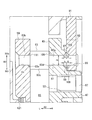
- FIG. 1 is an enlarged cross-sectional view of the arrow I in FIG.
- FIG. 2 is an enlarged cross-sectional view of the arrow II in FIG.
- FIG. 3A is a view showing the first nozzle ring in the variable nozzle unit according to the embodiment of the present invention
- FIG. 3B is a cross-sectional view taken along line III-III in FIG.
- 4 (a) is an enlarged view of the arrow IV in FIG. 3 (a)
- FIG. 4 (b) is one notch on the peripheral edge on one axial side of the first mounting hole of the first nozzle ring. It is a figure which shows the state in which chamfering was formed.
- FIG. 1 is an enlarged cross-sectional view of the arrow I in FIG.
- FIG. 2 is an enlarged cross-sectional view of the arrow II in FIG.
- FIG. 3A is a view showing the first nozzle ring in the variable nozzle unit according to the embodiment of the present invention
- FIG. 3B is
- FIG. 5A is a view showing a support ring in the variable nozzle unit according to the embodiment of the present invention
- FIG. 5B is a cross-sectional view taken along line VV in FIG. 5A
- 6 (a) is an enlarged view of the arrow VI in FIG. 5 (a)
- FIG. 6 (b) is a chamfer formed as one of the notches on the peripheral edge on the other side in the axial direction of the pin hole of the support ring.
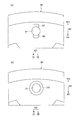
- FIG. 7 (a) and 7 (b) are cross-sectional views for explaining the operation of the embodiment of the present invention.
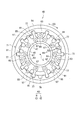
- FIG. 8 is a view of the variable nozzle unit according to the embodiment of the present invention as viewed from the link mechanism side.
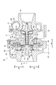
- FIG. 9 is a front sectional view of the variable capacity turbocharger according to the embodiment of the present invention.
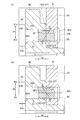
- FIG. 10 is a cross-sectional view showing a characteristic part of a modification of the embodiment of the present invention, and corresponds to FIG. 11A is a cross-sectional view taken along the line XI-XI in FIG. 10, and FIG. 11B is a chamfer formed as one of the notches on the peripheral edge on the other side in the axial direction of the pin hole of the support ring. It is a figure which shows a state.
- FIG. 12A and FIG. 12B are cross-sectional views for explaining the operation of a modification of the embodiment of the present invention.
- FIGS. As shown in the drawings, “L” is the left direction, “R” is the right direction, “AD” is the axial direction, “BD” is the radial direction, “BDi” is the radially inner side, “BDo” “Is radially outward and” CD “is circumferential.
- variable capacity supercharger 1 As shown in FIG. 9, the variable capacity supercharger 1 according to the embodiment of the present invention supercharges the air supplied to the engine using the pressure energy of the exhaust gas from the engine (not shown). Compress.
- the specific configuration of the variable capacity supercharger 1 is as follows.
- the variable capacity supercharger 1 includes a bearing housing 3.
- a pair of radial bearings 5 and a pair of thrust bearings 7 are provided in the bearing housing 3.
- a plurality of bearings 5 and 7 are rotatably provided with a rotor shaft (turbine shaft) 9 extending in the left-right direction.
- the rotor shaft 9 is rotatably provided in the bearing housing 3 via the plurality of bearings 5 and 7.
- Compressor housing 11 is provided on the right side of bearing housing 3.
- a compressor impeller 13 that compresses air by using centrifugal force is provided in the compressor housing 11 so as to be rotatable around its axis C (axis of the compressor impeller 13).
- the compressor impeller 13 is integrally connected to the right end portion of the rotor shaft 9.
- the compressor impeller 13 includes a compressor disk 15.
- the hub surface 15h of the compressor disk 15 extends radially outward from the right side (outside of the compressor impeller 13 in the radial direction).
- a plurality of compressor blades 17 are integrally formed on the hub surface 15 h of the compressor disk 15 at intervals in the circumferential direction (the circumferential direction of the hub surface 15 h of the compressor disk 15).
- An air inlet 19 for taking air into the compressor housing 11 is formed on the inlet side of the compressor impeller 13 in the compressor housing 11 (upstream side when viewed from the main air flow direction).
- the air intake 19 is connected to an air cleaner (not shown) that purifies air.
- an annular diffuser flow path 21 that pressurizes the compressed air is formed on the outlet side of the compressor impeller 13 between the bearing housing 3 and the compressor housing 11 (downstream side when viewed from the main flow direction of air).
- a spiral compressor scroll passage 23 is formed in the compressor housing 11.
- the compressor scroll channel 23 communicates with the diffuser channel 21.
- An air discharge port 25 for discharging the compressed air to the outside of the compressor housing 11 is formed at an appropriate position of the compressor housing 11.
- the air discharge port 25 is connected to an intake manifold (not shown) of the engine.
- An annular seal plate 27 that suppresses the leakage of compressed air to the thrust bearing 7 side is provided on the right side of the bearing housing 3.
- a turbine housing 29 is provided on the left side of the bearing housing 3.
- a turbine impeller 31 that generates a rotational force by using the pressure energy of the exhaust gas is provided so as to be rotatable around its axis C (axial center of the turbine impeller 31).
- the turbine impeller 31 is integrally connected to the left end portion of the rotor shaft 9.
- the turbine impeller 31 includes a turbine disk 33.
- the hub surface 33h of the turbine disk 33 extends from the left side (one side in the axial direction) to the radially outer side (the outer side in the radial direction of the turbine impeller 31).
- a plurality of turbine blades 35 are integrally formed on the hub surface 33h of the turbine disk 33 at intervals in the circumferential direction (the circumferential direction of the hub surface 33h of the turbine disk 33).
- a gas inlet 37 for taking exhaust gas into the turbine housing 29 is formed at an appropriate position of the turbine housing 29.
- the gas inlet 37 is connected to an exhaust manifold (not shown) of the engine.
- a spiral turbine scroll passage 39 is formed on the inlet side of the turbine impeller 31 inside the turbine housing 29 (upstream side when viewed from the main flow direction of the exhaust gas).
- the turbine scroll flow path 39 communicates with the gas intake port 37.
- a gas discharge port 41 for discharging the exhaust gas is formed on the outlet side of the turbine impeller 31 in the turbine housing 29 (downstream side when viewed from the flow direction of the exhaust gas).
- the gas discharge port 41 is connected to a catalyst (not shown) via a connecting pipe (not shown).
- variable capacity supercharger 1 is equipped with a variable nozzle unit 43 that adjusts the flow area (flow rate) of the exhaust gas supplied to the turbine impeller 31 side. Details of the configuration of the variable nozzle unit 43 are as follows.
- a first nozzle ring 45 as an annular first wall member is disposed concentrically with the turbine impeller 31 in the turbine housing 29. ing.
- An annular fitting protrusion 47 is formed on the right side surface of the first nozzle ring 45 so as to protrude rightward (one axial side).
- the fitting protrusion 47 is supported in a state of being fitted to an annular support portion 49 formed on the left side surface of the bearing housing 3.
- a plurality (at least three or more) of first mounting holes 51 are formed through the first nozzle ring 45 at intervals in the circumferential direction (predetermined circumferential direction).
- a plurality of support holes 53 are formed at equal intervals in the circumferential direction on the radially inner side of the first mounting hole 51 in the first nozzle ring 45.
- a plurality of guide claws 55 are formed on the fitting protrusion 47 of the first nozzle ring 45 at intervals in the circumferential direction (predetermined circumferential direction).
- Each guide claw 55 has a guide groove 57 having a U-shaped cross section on the tip side (radially outer side).
- a second nozzle ring 59 as an annular second wall member is integrated with the first nozzle ring 45 at a position facing the first nozzle ring 45 in the left-right direction (axial direction). It is provided concentrically.
- the second nozzle ring 59 has a circumferential direction (predetermined circumferential direction) so that a plurality (at least three or more) of second mounting holes 61 are aligned with the plurality of first mounting holes 51 of the first nozzle ring 45. Are formed at intervals.
- a plurality (at least three or more) of connecting pins 63 are provided between the first nozzle ring 45 and the second nozzle ring 59 so as to be integrally connected.
- the plurality of connecting pins 63 are arranged at intervals in the circumferential direction (predetermined circumferential direction).
- One end portion (one end portion in the axial direction) 63 a of each connecting pin 63 is caulked and coupled in a state of being inserted into the corresponding first mounting hole 51 of the first nozzle ring 45.
- each connecting pin 63 is caulked and coupled in a state of being inserted into the corresponding second mounting hole 61 of the second nozzle ring 59.
- An intermediate portion (intermediate portion between the one end portion 63a and the other end portion 63b) 63c of each connection pin 63 has a larger diameter than the outer diameters of the one end portion 63a and the other end portion 63b of the connection pin 63.
- a side surface (right side surface) on one side in the axial direction of the intermediate portion 63 c of each connection pin 63 is in contact with a facing surface (left side surface) of the first nozzle ring 45.
- each connecting pin 63 is in contact with the opposing surface (right side surface) of the second nozzle ring 59.
- the plurality of connecting pins 63 define the distance between the opposing surface of the first nozzle ring 45 and the opposing surface of the second nozzle ring 59.
- variable nozzles 65 are arranged in a circumferential direction (predetermined circle) so as to surround the turbine impeller 31. (Circumferential direction) at equal intervals.
- Each variable nozzle 65 is rotatable in the forward / reverse direction (open / close direction) around an axis parallel to the axis C of the turbine impeller 31 (axis of the variable nozzle 65).
- a nozzle shaft 67 is integrally formed on one axial side surface (right side surface) of each variable nozzle 65. Each nozzle shaft 67 is rotatably supported by the corresponding support hole 53 of the first nozzle ring 45.
- each variable nozzle 65 has one nozzle shaft 67, but another nozzle shaft (not shown) may be integrally formed on the other axial side surface (left side surface) of each variable nozzle 65. Good. In this case, each separate nozzle shaft is rotatably supported in another support hole (not shown) of the second nozzle ring 59.
- An annular link chamber 69 is defined on the opposite side (right side) of the opposing surface of the first nozzle ring 45.
- a link mechanism 71 for rotating the plurality of variable nozzles 65 in the forward / reverse direction (opening / closing direction) in synchronization is disposed in the link chamber 69.
- a specific configuration of the link mechanism 71 is as follows.
- the drive ring 73 is around the axis C of the turbine impeller 31 (axis of the first nozzle ring 45) C. Are provided so as to be rotatable in the forward and reverse directions.
- the drive ring 73 is rotated in the forward and reverse directions by driving a rotation actuator 75 such as an electric motor or a diaphragm actuator.
- a plurality of (as many as the variable nozzles 65) engagement recesses (engagement portions) 77 are formed in the drive ring 73 so as to be recessed radially outward and at equal intervals in the circumferential direction (the circumferential direction of the drive ring 73).
- Another engaging recess (another engaging portion) 79 is formed to be recessed outward in the radial direction.
- the base portion of the nozzle link member 81 is integrally connected to the nozzle shaft 67 of each variable nozzle 65. The tip of each nozzle link member 81 is engaged with a corresponding engagement recess 77 of the drive ring 73.
- the first nozzle The guide ring (not shown) disposed on the opposite surface of the ring 45 may be provided so as to be rotatable in the forward and reverse directions.
- the link mechanism 71 is disposed on the opposite surface side (left side surface side) of the second nozzle ring 59 instead of being disposed on the opposite surface side (inside the link chamber 69) of the first nozzle ring 45. You may be made to do.
- a drive shaft 83 is rotatable via a bush 85 so as to be rotatable around an axis parallel to the axis of the turbine impeller 31 (axis of the drive shaft 83).
- One end portion (right end portion) of the drive shaft 83 is connected to the rotation actuator 75 via the power transmission mechanism 87.
- the base end portion of the drive link member 89 is integrally connected to the other end portion (left end portion) of the drive shaft 83.
- the distal end portion of the drive link member 89 is engaged with another engagement recess 79 of the drive ring 73.
- the outer surface of the first nozzle ring 45 is opposite to the opposite surface (right side surface) of the first nozzle ring 45.
- a large-diameter support ring (annular support member) 91 is also provided. The inner edge portion of the support ring 91 is connected to the first nozzle ring 45 by caulking coupling of one end portions 63 a of the plurality of connecting pins 63.
- a plurality (at least three or more) of connecting pieces 93 for connecting to the first nozzle ring 45 project radially inward at the inner edge of the support ring 91 and are spaced apart in the circumferential direction (predetermined circumferential direction). Is formed.
- connection piece 93 is formed with a pin hole (third attachment hole) 95 through which one end 63a of the connection pin 63 is inserted.
- Each pin hole 95 is aligned with the corresponding first mounting hole 51 of the first nozzle ring 45.
- a plurality of pin holes 95 are formed through the inner edge of the support ring 91 at intervals in the circumferential direction so as to align with the plurality of first mounting holes 51 of the first nozzle ring 45.
- the outer edge portion of the support ring 91 is attached to the bearing housing 3 in a state of being sandwiched by cooperation with the turbine housing 29.
- the outer edge part of the support ring 91 is allowed to be displaced (finely moved) in the radial direction with respect to the bearing housing 3.
- the support ring 91 may be attached to the bearing housing 3 by mounting bolts (not shown).
- variable nozzle unit 43 the characteristic part of the variable nozzle unit 43 and the surrounding configuration will be described.
- the radius at the peripheral edge on one side (right side) in the axial direction of each first mounting hole 51 of the first nozzle ring 45 As shown in FIGS. 1, 3 (a), 3 (b), and 4 (a), the radius at the peripheral edge on one side (right side) in the axial direction of each first mounting hole 51 of the first nozzle ring 45.
- An outer notch 97 is formed on the outer side in the direction.
- An inner notch 99 is formed in a radially inner portion of the peripheral edge on the one axial side of each first mounting hole 51 of the first nozzle ring 45.
- the chamfer 101 may be formed as one of the notches.
- the axial length k of the outer notch 97, the inner notch 99, and the chamfer 101 is not less than 0.1 times, preferably not less than 0.3 times the outer diameter m of the one end portion 63a of the connecting pin 63. Is set. This is because the connecting pin 63 at the one end 63 a of the connecting pin 63 is generated when a radial thermal expansion difference between the first nozzle ring 45 and the support ring 91 occurs during operation of the variable displacement supercharger 1. This is because the shear stress is applied to a surface sufficiently larger than the surface VF perpendicular to the axial center 63s (see FIGS. 7A and 7B).
- a radially outer portion at the peripheral edge on the other axial side (left side) of each pin hole 95 of the support ring 91. Is formed with an outer notch 103.
- An inner notch 105 is formed in a radially inner portion of the peripheral edge on the other axial side of each pin hole 95 of the support ring 91.
- a chamfer 107 may be formed as one of them.
- the axial length g of the outer notch 103, the inner notch 105, and the chamfer 107 is the same as the reason for setting the axial length k of the outer notch 97 or the like.
- the outer diameter m is set to 0.1 times or more, preferably 0.3 times or more.
- a chamfer 109 is formed at the peripheral edge on the other side (left side) in the axial direction of each first mounting hole 51 of the first nozzle ring 45.
- a chamfer 111 is formed on the peripheral edge on one side (right side) in the axial direction of each second mounting hole 61 of the second nozzle ring 59. Note that a chamfer (not shown) may be formed on the peripheral edge of one axial direction of each pin hole 95 of the support ring 91.
- annular protrusion 113 is formed on the inner edge of the support portion 49 of the bearing housing 3 so as to protrude leftward (on the other side in the axial direction).
- An annular heat shield plate 115 that shields heat from the turbine impeller 31 is fitted to the protrusion 113.
- An annular fitting step portion 117 is formed in the outer edge portion (outer peripheral edge portion) of the heat shield plate 115 so as to be recessed inward in the radial direction. The fitting step 117 is fitted to the inner edge of the first nozzle ring 45.
- the first nozzle ring 45 is moved leftward so that the fitting step portion 117 of the heat shield plate 115 and the inner edge portion of the first nozzle ring 45 are pressed against each other.
- a disc spring 119 for biasing is provided.
- a ring 121 is provided.
- Exhaust gas taken in from the gas intake port 37 flows from the turbine impeller 31 inlet side to the outlet side via the turbine scroll passage 39. Thereby, a rotational force is generated by the pressure energy of the exhaust gas, and the rotor shaft 9 and the compressor impeller 13 rotate integrally with the turbine impeller 31. As a result, the air taken in from the air inlet 19 is compressed, and the compressed air is discharged from the air outlet 25 via the diffuser passage 21 and the compressor scroll passage 23 and supplied to the engine.
- variable displacement supercharger 1 When the engine speed is high and the flow rate of exhaust gas is high, the link mechanism 71 is operated by the rotating actuator 75 and the variable nozzles 65 are moved in the forward direction (opened). Direction). Thereby, the flow passage area (throat area) of the exhaust gas supplied to the turbine impeller 31 side is increased, and a large amount of exhaust gas is supplied. On the other hand, when the engine speed is low and the flow rate of exhaust gas is small, the link mechanism 71 is operated by the rotation actuator 75 and the plurality of variable nozzles 65 are rotated in the reverse direction (closed direction). .
- An outer notch 97 and an inner notch 99 are formed on the peripheral edge of each first mounting hole 51 of the first nozzle ring 45 in the axial direction, and the other axial direction of each pin hole 95 of the support ring 91 is on the other side.
- the outer notch 103 and the inner notch 105 are formed in the periphery. Therefore, during the operation of the variable displacement turbocharger 1, the first nozzle ring 45 and the support ring 91 are perpendicular to the axial center 63 s of the connection pin 63 at the one end portion 63 a of the connection pin 63 due to a difference in thermal expansion between the first nozzle ring 45 and the support ring 91.
- the shear stress acts on the surface (shear surface) SF1 or SF2 inclined according to the axial lengths k and g with respect to the smooth surface VF (see FIGS. 7A and 7B). Specifically, when the thermal expansion in the radial direction of the first nozzle ring 45 is larger than the thermal expansion in the radial direction of the support ring 91, the radius from the first nozzle ring 45 is increased as shown in FIG.
- a shearing force on the outer side in the direction and a shearing force on the inner side in the radial direction are generated from the support ring 91 (see the white arrow), respectively, and a shearing stress acts on the inclined surface (shearing surface) SF1 in one end portion 63a of the connecting pin 63 It works on one end 63a of the connecting pin 63.
- the position of the shear force acting from the first nozzle ring 45 and the position of the shear force acting from the support ring 91 are in the axial direction of the connecting pin 63 by an amount corresponding to the outer notches 97 and 103 and the inner notches 99 and 105. Separate. As a result, even if the ambient temperature difference between the first nozzle ring 45 and the support ring 91 increases during the operation of the variable displacement turbocharger 1, the shear stress acting on the one end portion 63a of the connecting pin 63 increases. Can be suppressed.
- a chamfer 109 is formed on the peripheral edge on the other axial side of each first mounting hole 51 of the first nozzle ring 45. For this reason, the boundary portion 63d between the one end portion 63a and the intermediate portion 63c in the connecting pin 63 does not come into contact with a sharp portion (see FIG. 1). Similarly, a chamfer 111 is formed at the peripheral edge on one axial side of each second mounting hole 61 of the second nozzle ring 59. Therefore, it becomes difficult for the boundary portion 63e between the other end portion 63b and the intermediate portion 63c in the connecting pin 63 to contact a sharp portion (see FIG. 1).
- the embodiment of the present invention even if the ambient temperature difference between the first nozzle ring 45 and the support ring 91 increases during the operation of the variable displacement turbocharger 1, It can suppress that the working shear stress becomes high. Moreover, even if stress concentration occurs in the boundary portions 63d and 63e in the connecting pin 63 due to the radial thermal expansion difference between the first nozzle ring 45 and the support ring 91 depending on the operation state of the variable capacity supercharger 1, The stress concentration can be relaxed.
- An outer notch 97 or the like is formed on the peripheral edge on one axial side of each first mounting hole 51 of the first nozzle ring 45, and an outer notch 103 or the like is formed on the peripheral edge on the other axial side of each pin hole 95 of the support ring 91.
- the following configuration may be adopted.
- An outer notch 123 is formed in this part.
- An inner notch 125 is formed in a radially inner portion including the alignment portion on the outer peripheral surface of the one end portion 63 a of each connecting pin 63.
- a circumferential groove 127 may be formed.
- the axial length j of the outer notch 123, the inner notch 125, and the circumferential groove 127 is the same as the reason for setting the axial length k such as the outer notch 97 (see FIG. 1).
- the outer diameter m of the one end 63a of 63 is set to 0.2 times or more, preferably 0.6 times or more.
- the position of the shear force acting from the first nozzle ring 45 and the position of the shear force acting from the support ring 91 are separated in the axial direction of the connecting pin 63 by an amount corresponding to the outer notch 123, the inner notch 125, and the like.
- the present invention is not limited to the description of the above-described embodiment.
- the remaining The present invention can be implemented in various modes, such as omitting the notch. Also, the scope of rights encompassed by the present invention is not limited to these embodiments.
- connection pin even if an ambient temperature difference (surrounding gas temperature difference) between the first wall member and the support ring increases during operation of the variable capacity supercharger, one end of the connection pin It is possible to suppress the influence on the shear stress and shear strain acting on the.
Landscapes
- Engineering & Computer Science (AREA)
- Mechanical Engineering (AREA)
- General Engineering & Computer Science (AREA)
- Chemical & Material Sciences (AREA)
- Combustion & Propulsion (AREA)
- Chemical Kinetics & Catalysis (AREA)
- General Chemical & Material Sciences (AREA)
- Physics & Mathematics (AREA)
- Geometry (AREA)
- Supercharger (AREA)
- Control Of Turbines (AREA)
Abstract
サポートリング91の内縁部は、複数の連結ピン63の一端部のかしめ結合によって第1ノズルリング45に連結され、第1ノズルリング45の各第1取付穴51の軸方向一方側の周縁における半径方向外側の部位にアウタ切欠97が形成され、第1ノズルリング45の各第1取付穴51の軸方向一方側の周縁における半径方向内側の部位にインナ切欠99が形成され、サポートリング91の各ピン穴95の軸方向他方側の周縁における半径方向外側の部位にアウタ切欠103が形成され、サポートリング91の各ピン穴95の軸方向他方側の周縁における半径方向内側の部位にインナ切欠105が形成される。
Description
本発明は、可変容量型過給機におけるタービンインペラ側へ供給される排気ガスの流路面積(流量)を調整する 可変ノズルユニット等に関する。
可変容量型過給機は、タービンインペラ側へ供給される排気ガスの流路面積(流量)を調整する可変ノズルユニットを装備している。 関連技術は、日本国特許公開公報特開2009-243431号(特許文献1)および特開2009-243300号(特許文献2)に例示される。関連技術に係る可変ノズルユニットの具体的な構成は以下の通りである。
タービンハウジング内には、環状の第1壁部材としての第1ノズルリングがタービンインペラと同心状に配設されている。この第1ノズルリングには、複数の第1取付穴が円周方向(所定の円周方向)に間隔を置いて貫通形成(貫通して形成)されている。また、第1ノズルリングに対して軸方向(タービンインペラの軸方向)に離隔した位置には、環状の第2壁部材としての第2ノズルリングが第1ノズルリングと一体的に設けられている。この第2ノズルリングには、複数の第2取付穴が第1ノズルリングの複数の第1取付穴に整合するように円周方向に間隔を置いて貫通形成されている。
第1ノズルリングと第2ノズルリングとの間には、複数の連結ピンが一体的に連結するように設けられている。複数の連結ピンは、円周方向(所定の円周方向)に間隔を置いて並んでいる。各連結ピンの一端部(軸方向の一端部)は、第1ノズルリングの対応する第1取付穴に挿通した状態で結合されている。各連結ピンの他端部(軸方向の他端部)は、第2ノズルリングの対応する第2取付穴に挿通した状態で結合されている。各連結ピンの中間部の軸方向一方側の側面は、第1ノズルリングの対向面に当接している。各連結ピンの中間部の軸方向他方側の側面は、第2ノズルリングの対向面に当接している。
第1ノズルリングの対向面と第2ノズルリングの対向面との間には、複数の可変ノズルが円周方向(所定の円周方向)に等間隔に配設されている。各可変ノズルは、タービンインペラの軸心に平行な軸心(可変ノズルのノズル軸の軸心)周りに正逆方向(開閉方向)へ回動可能である。第1ノズルリングの対向面の反対面側に区画形成したリンク室には、複数の可変ノズルを正逆方向へ同期して回動させるためのリンク機構が配設されている。複数の可変ノズルを正方向(開方向)へ同期して回動させると、タービンインペラ側へ供給される排気ガスの流路面積(スロート面積)が大きくなる。一方、複数の可変ノズルを逆方向(閉方向)へ同期して回動させると、タービンインペラ側へ供給される排気ガスの流路面積が小さくなる。
第1ノズルリングの対向面の反対面には、第1ノズルリングの外径よりも大径のサポートリングが一体的に設けられている。サポートリングの内縁部(内周縁部)は、複数の連結ピンの一端部の結合によって一体的に連結されている。サポートリングの内縁部には、連結ピンの一端部を挿通させるための複数のピン穴(第3取付穴)が第1ノズルリングの複数の前記第1取付穴に整合するように円周方向に間隔を置いて貫通形成されている。サポートリングの外縁部(外周縁部)は、ベアリングハウジングにタービンハウジングとの協働により挟持された状態で取付けられる。
可変容量型過給機の運転状況によっては、第1ノズルリングの周辺温度(周辺のガス温度)がサポートリングの周辺温度に比べて高くなり、反対に、第1ノズルリングの周辺温度がサポートリングの周辺温度に比べて低くなる可能性がある。換言すれば、可変容量型過給機の運転中に、第1ノズルリングとサポートリングとの周辺温度差(周辺のガス温度差)が発生する可能性がある。すると、第1ノズルリングとサポートリングとの半径方向の熱膨張差が生じる。この熱膨張差によって、連結ピンの一端部における連結ピンの軸心に垂直な面(剪断面)に剪断応力が働く。
さらに、エンジン側の要請に伴い、可変容量型過給機の運転中における第1ノズルリングとサポートリングとの周辺温度差が増大する可能性がある。この場合、可変容量型過給機の運転状況によっては、連結ピンの一端部に働く剪断応力への影響が懸念される。
本発明によれば、可変容量型過給機の運転中における第1壁部材とサポートリングとの周辺温度差が増大しても、前記連結ピンの一端部に働く剪断応力への影響を抑制することができる可変ノズルユニットを提供することができる。
本発明の技術的側面によれば、可変容量型過給機におけるタービンインペラ側へ供給される排気ガスの流路面積を可変する可変ノズルユニットにおいて、前記可変容量型過給機におけるタービンハウジング内に前記タービンインペラと同心状に配設され、複数の取付穴が円周方向に間隔を置いて貫通形成された環状の第1壁部材と、前記第1壁部材に対して軸方向に離隔対向した位置に設けられた環状の第2壁部材と、前記第1壁部材と前記第2壁部材との間に一体的に連結するように設けられ、一端部(軸方向の一端部)が前記第1壁部材の対応する前記取付穴に挿通した状態で結合され、円周方向に間隔を置いて並んだ複数の連結ピンと、前記第1壁部材の対向面と前記第2壁部材の対向面との間に円周方向(所定の円周方向)に間隔を置いて配設され、前記タービンインペラの軸心に平行な軸心(可変ノズルのノズル軸の軸心)周りに正逆方向へ回動可能な複数の可変ノズルと、複数の前記可変ノズルを同期して回動させるためのリンク機構と、前記第1壁部材の対向面の反対面に設けられ、前記第1壁部材に複数の前記連結ピンの一端部の結合によって一体的に連結され、前記連結ピンの一端部を挿通させるための複数のピン穴が前記第1壁部材の複数の前記取付穴に整合するように貫通形成されたサポートリング(環状のサポート部材)と、を具備し、前記第1壁部材の各取付穴の軸方向一方側の周縁における半径方向外側の部位又は半径方向内側の部位、前記サポートリングの各ピン穴の軸方向他方側の周縁における半径方向外側の部位又は半径方向内側の部位、若しくは各連結ピンの一端部の外周面における前記第1壁部材と前記サポートリングとの境界位置に整合する整合箇所を含む半径方向外側の部位又は半径方向内側の部位のうちの少なくともいずれか1つの部位に、切欠が形成されていることを要旨とする。
なお、本願の明細書及び特許請求の範囲において、「配設され」とは、直接的に配設されたことの他に、別部材を介して間接的に配設されたことを含む意である。「設けられ」とは、直接的に設けられたことの他に、別部材を介して間接的に設けられたことを含む意である。「環状の第2壁部材」は、前記タービンハウジング等の一部を構成するものであっても構わない。「軸方向」とは、特に断らない限り、タービンインペラの軸方向(換言すれば、第1壁部材、第2壁部材、連結ピン、又はサポートリングの軸方向)のことをいう。「軸方向一方側」とは、軸方向の一方側のことをいう。「軸方向他方側」とは、軸方向の他方側のことをいう。「結合」とは、カシメ結合、溶接結合、ねじ結合等を含む意である。「半径方向」とは、特に断らない限り、タービンインペラの半径方向(換言すれば、第1壁部材、第2壁部材、及びサポートリングの半径方向)のことをいう。
本発明の技術的側面によると、前記可変容量型過給機の運転中、エンジン回転数が高回転域にあって、排気ガスの流量が多い場合には、前記リンク機構を作動させつつ、複数の前記可変ノズルを正方向(開方向)へ同期して回動させる。これにより、前記タービンインペラ側へ供給される排気ガスのガス流路面積(スロート面積)を大きくする。
一方、エンジン回転数が低回転域にあって、排気ガスの流量が少ない場合には、前記リンク機構を作動させつつ、複数の前記可変ノズルを逆方向(閉方向)へ同期して回動させる。これにより、前記タービンインペラ側へ供給される排気ガスのガス流路面積を小さくする 。
前記第1壁部材の各第1取付穴の一方側の周縁における半径方向外側の部位等に切欠が形成されている。これにより、前記可変容量型過給機の運転中に、前記第1壁部材と前記サポートリングとの半径方向の熱膨張差が生じた場合に、前記連結ピンの一端部における前記連結ピンの軸心に垂直な面に対して傾斜した面(剪断面)に剪断応力が働く。つまり、前記可変容量型過給機の運転中に、前記第1壁部材と前記サポートリングとの半径方向の熱膨張差が生じた場合に、前記連結ピンの一端部における前記連結ピンの軸心に垂直な面よりも大きな面に剪断応力が働く。また、前記第1壁部材から働く剪断力の作用位置と前記サポートリングから働く剪断力の作用位置は、切欠に応じた分だけ前記連結ピンの軸方向に離隔する 。
本発明の他の技術的側面によれば、エンジンからの排気ガスのエネルギーを利用して、前記エンジン側に供給される空気を過給する可変容量型過給機において、前記技術的側面を有する可変ノズルユニットを具備することを要旨とする。
したがって、前記技術的側面による作用と同様の作用を奏する。
本発明の実施形態について図1から図12を参照して説明する。なお、図面に示すとおり、「L」は、左方向、「R」は、右方向、「AD」は、軸方向、「BD」は、半径方向、「BDi」は、半径方向内側、「BDo」は、半径方向外側、「CD」は、円周方向である。
図9に示すように、本発明の実施形態に係る可変容量型過給機1は、エンジン(図示省略)からの排気ガスの圧力エネルギーを利用して、エンジンに供給される空気を過給(圧縮)する。可変容量型過給機1の具体的な構成等は、以下の通りである。
可変容量型過給機1は、ベアリングハウジング3を具備している。ベアリングハウジング3内には、一対のラジアルベアリング5及び一対のスラストベアリング7が設けられている。複数のベアリング5,7には、左右方向へ延びたロータ軸(タービン軸)9が回転可能に設けられている。換言すれば、ベアリングハウジング3には、ロータ軸9が複数のベアリング5,7を介して回転可能に設けられている。
ベアリングハウジング3の右側には、コンプレッサハウジング11が設けられている。コンプレッサハウジング11内には、遠心力を利用して空気を圧縮するコンプレッサインペラ13がその軸心(コンプレッサインペラ13の軸心)C周りに回転可能に設けられている。コンプレッサインペラ13は、ロータ軸9の右端部に一体的に連結されている。コンプレッサインペラ13は、コンプレッサディスク15を備えている。コンプレッサディスク15のハブ面15hは、右側から半径向外側(コンプレッサインペラ13の半径方向の外側)へ延びている。コンプレッサディスク15のハブ面15hには、複数のコンプレッサブレード17が周方向(コンプレッサディスク15のハブ面15hの周方向)に間隔を置いて一体形成されている。
コンプレッサハウジング11におけるコンプレッサインペラ13の入口側(空気の主流方向から見て上流側)には、空気をコンプレッサハウジング11内に取入れるための空気取入口19が形成されている。空気取入口19は、空気を浄化するエアクリーナ(図示省略)に接続する。ベアリングハウジング3とコンプレッサハウジング11との間におけるコンプレッサインペラ13の出口側(空気の主流方向から見て下流側)には、圧縮された空気を昇圧する環状のディフューザ流路21が形成されている。コンプレッサハウジング11の内部には、渦巻き状のコンプレッサスクロール流路23が形成されている。コンプレッサスクロール流路23は、ディフューザ流路21に連通している。コンプレッサハウジング11の適宜位置には、圧縮された空気をコンプレッサハウジング11の外側へ排出するための空気排出口25が形成されている。空気排出口25は、エンジンの吸気マニホールド(図示省略)に接続する。
なお、ベアリングハウジング3の右側部には、スラストベアリング7側への圧縮空気の漏れを抑える環状のシールプレート27が設けられている。
図2及び図9に示すように、ベアリングハウジング3の左側には、タービンハウジング29が設けられている。タービンハウジング29内には、排気ガスの圧力エネルギーを利用して回転力を発生させるタービンインペラ31がその軸心(タービンインペラ31の軸心)C周りに回転可能に設けられている。タービンインペラ31は、ロータ軸9の左端部に一体的に連結されている。タービンインペラ31は、タービンディスク33を備えている。タービンディスク33のハブ面33hは、左側(軸方向一方側)から半径方向外側(タービンインペラ31の半径方向の外側)へ延びている。タービンディスク33のハブ面33hには、複数のタービンブレード35が周方向(タービンディスク33のハブ面33hの周方向)に間隔を置いて一体形成されている。
タービンハウジング29の適宜位置には、排気ガスをタービンハウジング29内に取入れるためのガス取入口37が形成されている。ガス取入口37は、エンジンの排気マニホールド(図示省略)に接続される。タービンハウジング29の内部におけるタービンインペラ31の入口側(排気ガスの主流方向から見て上流側)には、渦巻き状のタービンスクロール流路39が形成されている。タービンスクロール流路39は、ガス取入口37に連通している。タービンハウジング29におけるタービンインペラ31の出口側(排気ガスの流れ方向から見て下流側)には、排気ガスを排出するためのガス排出口41が形成されている。ガス排出口41は、接続管(図示省略)を介して触媒(図示省略)に接続される。
可変容量型過給機1は、タービンインペラ31側へ供給される排気ガスの流路面積(流量)を調整する可変ノズルユニット43を装備している。可変ノズルユニット43の構成の詳細は、次の通りである。
図2及び図3(a)、図3(b)に示すように、タービンハウジング29内には、環状の第1壁部材としての第1ノズルリング45がタービンインペラ31と同心状に配設されている。第1ノズルリング45の右側面には、環状の嵌合突部47が右方向(軸方向一方側)へ突出して形成されている。嵌合突部47は、ベアリングハウジング3の左側面に形成された環状の支持部49に嵌合した状態で支持されている。第1ノズルリング45には、複数(少なくとも3つ以上)の第1取付穴51が円周方向(所定の円周方向)に間隔を置いて貫通形成(貫通して形成)されている。第1ノズルリング45における第1取付穴51の半径方向内側には、複数の支持穴53が円周方向に等間隔に貫通形成されている。第1ノズルリング45の嵌合突部47には、複数のガイド爪55が円周方向(所定の円周方向)に間隔を置いて形成されている。各ガイド爪55は、先端側(半径方向外側)に、断面U字状のガイド溝57を有している。
図2に示すように、第1ノズルリング45に左右方向(軸方向)に離隔対向した位置には、環状の第2壁部材としての第2ノズルリング59が第1ノズルリング45と一体的かつ同心状に設けられている。第2ノズルリング59には、複数(少なくとも3つ以上)の第2取付穴61が第1ノズルリング45の複数の第1取付穴51に整合するように円周方向(所定の円周方向)に間隔を置いて貫通形成されている。なお、前述の特許文献1及び特許文献2に示すように、第2ノズルリング59が複数のタービンブレード35のチップ35tを覆う円筒状のシュラウド部(図示省略)を有するようにしてもよい。
図1及び図2に示すように、第1ノズルリング45と第2ノズルリング59の間には、複数(少なくとも3つ以上)の連結ピン63が一体的に連結するように設けられている。複数の連結ピン63は、円周方向(所定の円周方向)に間隔を置いて並んでいる。各連結ピン63の一端部(軸方向の一端部)63aは、第1ノズルリング45の対応する第1取付穴51に挿通した状態でかしめ結合されている。各連結ピン63の他端部(軸方向の他端部)63bは、第2ノズルリング59の対応する第2取付穴61に挿通した状態でかしめ結合されている。
各連結ピン63の中間部(一端部63aと他端部63bの中間部)63cは、連結ピン63の一端部63a及び他端部63bの外径よりも大径になっている。各連結ピン63の中間部63cの軸方向一方側の側面(右側面)は、第1ノズルリング45の対向面(左側面)に当接している。各連結ピン63の中間部63cの軸方向他方側の側面(左側面)は、第2ノズルリング59の対向面(右側面)に当接している。換言すれば、複数の連結ピン63は、第1ノズルリング45の対向面と第2ノズルリング59の対向面との間隔を規定する。
各連結ピン63の中間部(一端部63aと他端部63bの中間部)63cは、連結ピン63の一端部63a及び他端部63bの外径よりも大径になっている。各連結ピン63の中間部63cの軸方向一方側の側面(右側面)は、第1ノズルリング45の対向面(左側面)に当接している。各連結ピン63の中間部63cの軸方向他方側の側面(左側面)は、第2ノズルリング59の対向面(右側面)に当接している。換言すれば、複数の連結ピン63は、第1ノズルリング45の対向面と第2ノズルリング59の対向面との間隔を規定する。
図2に示すように、第1ノズルリング45の対向面と第2ノズルリング59の対向面との間には、複数の可変ノズル65がタービンインペラ31を囲むように円周方向(所定の円周方向)に等間隔に配設されている。各可変ノズル65は、タービンインペラ31の軸心Cに平行な軸心(可変ノズル65の軸心)周りに正逆方向(開閉方向)へ回動可能である。各可変ノズル65の軸方向一方側の側面(右側面)には、ノズル軸67が一体形成されている。各ノズル軸67は、第1ノズルリング45の対応する支持穴53に回動可能に支持されている。なお、複数の可変ノズル65が円周方向に等間隔に並んでいるが、不等間隔に並んでいてもよい。各可変ノズル65は1つのノズル軸67を有してあるが、各可変ノズル65の軸方向他方側の側面(左側面)に別のノズル軸(図示省略)が一体形成されるようにしてもよい。この場合には、各別のノズル軸が第2ノズルリング59の別の支持穴(図示省略)に回動可能に支持される。
第1ノズルリング45の対向面の反対面側(右側面側)には、環状のリンク室69が区画形成されている。リンク室69内には、複数の可変ノズル65を同期して正逆方向(開閉方向)へ回動させるためのリンク機構71が配設されている。リンク機構71の具体的な構成は、次の通りである。
図2及び図8に示すように、第1ノズルリング45の複数のガイド爪55のガイド溝57には、駆動リング73がタービンインペラ31の軸心(第1ノズルリング45の軸心)C周りに正逆方向へ回動可能に設けられている。駆動リング73は、電動モータ又はダイヤフラムアクチュエータ等の回動アクチュエータ75の駆動によって正逆方向へ回動する。駆動リング73には、複数(可変ノズル65と同数)の係合凹部(係合部)77が半径方向外側へ窪みかつ周方向(駆動リング73の周方向)に等間隔に形成されている。駆動リング73の適宜位置には、別の係合凹部(別の係合部)79が半径方向外側へ窪んで形成されている。各可変ノズル65のノズル軸67には、ノズルリンク部材81の基部が一体的に連結されている。各ノズルリンク部材81の先端部は、駆動リング73の対応する係合凹部77に係合してある。
なお、駆動リング73が第1ノズルリング45の複数のガイド爪55のガイド溝57に正逆方向へ回動可能に設けられる代わりに、特許文献1及び特許文献2に示すように、第1ノズルリング45の対向面の反対面に配設したガイドリング(図示省略)に正逆方向へ回動可能に設けられるようにしてもよい。リンク機構71が第1ノズルリング45の対向面の反対面側(リンク室69内)に配設される代わりに、第2ノズルリング59の対向面の反対面側(左側面側)に配設されるようにしてもよい。複数の可変ノズル65が円周方向に不等間隔に並んでいる場合には、複数の係合凹部77が不等間隔に並ぶ。
なお、駆動リング73が第1ノズルリング45の複数のガイド爪55のガイド溝57に正逆方向へ回動可能に設けられる代わりに、特許文献1及び特許文献2に示すように、第1ノズルリング45の対向面の反対面に配設したガイドリング(図示省略)に正逆方向へ回動可能に設けられるようにしてもよい。リンク機構71が第1ノズルリング45の対向面の反対面側(リンク室69内)に配設される代わりに、第2ノズルリング59の対向面の反対面側(左側面側)に配設されるようにしてもよい。複数の可変ノズル65が円周方向に不等間隔に並んでいる場合には、複数の係合凹部77が不等間隔に並ぶ。
図2に示すように、ベアリングハウジング3の左側部には、駆動軸83がタービンインペラ31の軸心に平行な軸心(駆動軸83の軸心)周りに回動可能にブッシュ85を介して設けられている。駆動軸83の一端部(右端部)は、動力伝達機構87を介して回動アクチュエータ75に接続されている。駆動軸83の他端部(左端部)には、駆動リンク部材89の基端部が一体的に連結されている。駆動リンク部材89の先端部は、駆動リング73の別の係合凹部79に係合している。
図1、図2、及び図5(a)、図5(b)に示すように、第1ノズルリング45の対向面の反対面(右側面)には、第1ノズルリング45の外径よりも大径のサポートリング(環状のサポート部材)91が設けられている。サポートリング91の内縁部は、複数の連結ピン63の一端部63aのかしめ結合によって第1ノズルリング45に連結されている。サポートリング91の内縁部には、第1ノズルリング45に連結するための複数(少なくとも3つ以上)の連結片93が半径向内側へ突出しかつ円周方向(所定の円周方向)に間隔を置いて形成されている。各連結片93には連結ピン63の一端部63aを挿通させるためのピン穴(第3取付穴)95が貫通形成されている。各ピン穴95は第1ノズルリング45の対応する第1取付穴51に整合している。
換言すれば、サポートリング91の内縁部には、複数のピン穴95が第1ノズルリング45の複数の第1取付穴51に整合するように円周方向に間隔を置いて貫通形成されている。更に、サポートリング91の外縁部は、ベアリングハウジング3にタービンハウジング29との協働により挟持された状態で取付けられている。これにより、サポートリング91の外縁部は、ベアリングハウジング3に対して半径方向の変位(微動)が許容されている。なお、サポートリング91の外縁部がベアリングハウジング3にタービンハウジング29との協働により挟持された状態で取付けられる代わりに、ベアリングハウジング3に取付ボルト(図示省略)によって取付けられてもよい。
換言すれば、サポートリング91の内縁部には、複数のピン穴95が第1ノズルリング45の複数の第1取付穴51に整合するように円周方向に間隔を置いて貫通形成されている。更に、サポートリング91の外縁部は、ベアリングハウジング3にタービンハウジング29との協働により挟持された状態で取付けられている。これにより、サポートリング91の外縁部は、ベアリングハウジング3に対して半径方向の変位(微動)が許容されている。なお、サポートリング91の外縁部がベアリングハウジング3にタービンハウジング29との協働により挟持された状態で取付けられる代わりに、ベアリングハウジング3に取付ボルト(図示省略)によって取付けられてもよい。
続いて、可変ノズルユニット43の特徴部分及び周辺の構成について説明する。
図1、図3(a)、図3(b)、及び図4(a)に示すように、第1ノズルリング45の各第1取付穴51の軸方向一方側(右側)の周縁における半径方向外側の部位には、アウタ切欠97が形成されている。第1ノズルリング45の各第1取付穴51の軸方向一方側の周縁における半径方向内側の部位には、インナ切欠99が形成されている。第1ノズルリング45の各第1取付穴51の軸方向一方側の周縁にアウタ切欠97及びインナ切欠99が形成される代わりに、図4(b)に示すように、加工の容易性を考慮して、切欠の1つとして面取り101が形成されるようにしてもよい。
ここで、アウタ切欠97、インナ切欠99、及び面取り101の軸方向の長さkは、連結ピン63の一端部63aの外径mの0.1倍以上、好ましくは、0.3倍以上に設定されている。この理由は、可変容量型過給機1の運転中に、第1ノズルリング45とサポートリング91との半径方向の熱膨張差が生じた場合に、連結ピン63の一端部63aにおける連結ピン63の軸心63sに垂直な面VFよりも十分に大きな面に剪断応力が働くようにするためである(図7(a)、図7(b)参照)。
ここで、アウタ切欠97、インナ切欠99、及び面取り101の軸方向の長さkは、連結ピン63の一端部63aの外径mの0.1倍以上、好ましくは、0.3倍以上に設定されている。この理由は、可変容量型過給機1の運転中に、第1ノズルリング45とサポートリング91との半径方向の熱膨張差が生じた場合に、連結ピン63の一端部63aにおける連結ピン63の軸心63sに垂直な面VFよりも十分に大きな面に剪断応力が働くようにするためである(図7(a)、図7(b)参照)。
図1、図5(a)、図5(b)、及び図6(a)に示すように、サポートリング91の各ピン穴95の軸方向他方側(左側)の周縁における半径方向外側の部位には、アウタ切欠103が形成されている。サポートリング91の各ピン穴95の軸方向他方側の周縁における半径方向内側の部位には、インナ切欠105が形成されている。サポートリング91の各ピン穴95の軸方向他方側の周縁にアウタ切欠103及びインナ切欠105が形成される代わりに、図6(b)に示すように、加工の容易性を考慮して、切欠の1つとして面取り107が形成されるようにしてもよい。ここで、アウタ切欠103、インナ切欠105、及び面取り107の軸方向の長さgは、アウタ切欠97等の軸方向の長さkの設定理由と同じ理由により、連結ピン63の一端部63aの外径mの0.1倍以上、好ましくは、0.3倍以上に設定されている。
図1に示すように、第1ノズルリング45の各第1取付穴51の軸方向他方側(左側)の周縁には、面取り109が形成されている。第2ノズルリング59の各第2取付穴61の軸方向一方側(右側)の周縁には、面取り111が形成されている。なお、サポートリング91の各ピン穴95の軸方向一方側の周縁に面取り(図示省略)が形成されるようにしてもよい。
図2に示すように、環状の突起部113が、ベアリングハウジング3の支持部49の内縁部に左方向(軸方向他方側)へ突出して形成されている。突起部113には、タービンインペラ31側からの熱を遮蔽する環状の遮熱板115が嵌合して設けられている。遮熱板115の外縁部(外周縁部)には、環状の嵌合段部117が半径方向内側へ窪んで形成されている。嵌合段部117は、第1ノズルリング45の内縁部に嵌合している。ベアリングハウジング3の突起部113における遮熱板115の右側には、遮熱板115の嵌合段部117と第1ノズルリング45の内縁部を圧接させるように第1ノズルリング45を左方向へ付勢する皿バネ119が設けられている。第2ノズルリング59の内周面とタービンハウジング29の適宜箇所との間には、第2ノズルリング59の対向面の反対面側(左側面側)からの排気ガスの漏れを抑える複数のシールリング121が設けられている。
続いて、本発明の実施形態の作用及び効果について説明する。
ガス取入口37から取入れた排気ガスがタービンスクロール流路39を経由してタービンインペラ31入口側から出口側へ流通する。これにより、排気ガスの圧力エネルギーによって回転力が発生し、ロータ軸9及びコンプレッサインペラ13がタービンインペラ31と一体的に回転する。その結果、空気取入口19から取入れた空気が圧縮され、圧縮された空気はディフューザ流路21及びコンプレッサスクロール流路23を経由して空気排出口25から排出され、エンジンに供給される。
可変容量型過給機1の運転中、エンジン回転数が高く、排気ガスの流量が多い場合には、回動アクチュエータ75によってリンク機構71を作動させつつ、複数の可変ノズル65を正方向(開方向)へ同期して回動させる。これにより、タービンインペラ31側へ供給される排気ガスの流路面積(スロート面積)を大きくして、多くの排気ガスを供給する。一方、エンジン回転数が低く、排気ガスの流量が少ない場合には、回動アクチュエータ75によってリンク機構71を作動させつつ、複数の可変ノズル65を逆方向(閉方向)へ同期して回動させる。これにより、タービンインペラ31側へ供給される排気ガスの流路面積を小さくして、排気ガスの流速を高めて、タービンインペラ31の仕事量を十分に確保する。その結果、排気ガスの流量の多少に関係なく、タービンインペラ31によって回転力を十分かつ安定的に発生させることができる。
第1ノズルリング45の各第1取付穴51の軸方向一方側の周縁にアウタ切欠97及びインナ切欠99(又は面取り101)が形成され、サポートリング91の各ピン穴95の軸方向他方側の周縁にアウタ切欠103及びインナ切欠105(又は面取り107)が形成されている。そのため、可変容量型過給機1の運転中に、第1ノズルリング45とサポートリング91との半径方向の熱膨張差によって、連結ピン63の一端部63aにおける連結ピン63の軸心63sに垂直な面VFに対し軸方向の長さkおよびgに相応して傾斜した面(剪断面)SF1又はSF2に剪断応力が働く(図7(a)、図7(b)参照)。
具体的には、第1ノズルリング45の半径方向の熱膨張がサポートリング91の半径方向の熱膨張よりも大きい場合には、図7(a)に示すように、第1ノズルリング45から半径方向外側の剪断力及びサポートリング91から半径方向内側の剪断力がそれぞれ発生して(白抜き矢印参照)、連結ピン63の一端部63aにおける前記傾斜した面(剪断面)SF1に剪断応力が働く連結ピン63の一端部63aに働く。
サポートリング91の半径方向の熱膨張が第1ノズルリング45の半径方向の熱膨張よりも大きい場合には、図7(b)に示すように、第1ノズルリング45から半径方向内側の剪断力及びサポートリング91から半径方向外側の剪断力がそれぞれ発生して(白抜き矢印参照)、連結ピン63の一端部63aにおける前記傾斜した面(剪断面)SF2に剪断応力が働く。
したがって、可変容量型過給機1の運転中に、第1ノズルリング45とサポートリング91との半径方向の熱膨張差が生じた場合に、連結ピン63の一端部63aにおける連結ピン63の軸心63sに垂直な面VFよりも大きな面SF1又はSF2に剪断応力が働く。その結果、連結ピン63の一端部63aで発生する半径方向の剪断ひずみを抑制することができる。
また、第1ノズルリング45から働く剪断力の作用位置とサポートリング91から働く剪断力の作用位置は、アウタ切欠97,103及びインナ切欠99,105等に応じた分だけ連結ピン63の軸方向に離隔する。これにより、可変容量型過給機1の運転中における第1ノズルリング45とサポートリング91との周辺温度差が増大しても、連結ピン63の一端部63aに働く剪断応力が大きくなることを抑制することができる。
具体的には、第1ノズルリング45の半径方向の熱膨張がサポートリング91の半径方向の熱膨張よりも大きい場合には、図7(a)に示すように、第1ノズルリング45から半径方向外側の剪断力及びサポートリング91から半径方向内側の剪断力がそれぞれ発生して(白抜き矢印参照)、連結ピン63の一端部63aにおける前記傾斜した面(剪断面)SF1に剪断応力が働く連結ピン63の一端部63aに働く。
サポートリング91の半径方向の熱膨張が第1ノズルリング45の半径方向の熱膨張よりも大きい場合には、図7(b)に示すように、第1ノズルリング45から半径方向内側の剪断力及びサポートリング91から半径方向外側の剪断力がそれぞれ発生して(白抜き矢印参照)、連結ピン63の一端部63aにおける前記傾斜した面(剪断面)SF2に剪断応力が働く。
したがって、可変容量型過給機1の運転中に、第1ノズルリング45とサポートリング91との半径方向の熱膨張差が生じた場合に、連結ピン63の一端部63aにおける連結ピン63の軸心63sに垂直な面VFよりも大きな面SF1又はSF2に剪断応力が働く。その結果、連結ピン63の一端部63aで発生する半径方向の剪断ひずみを抑制することができる。
また、第1ノズルリング45から働く剪断力の作用位置とサポートリング91から働く剪断力の作用位置は、アウタ切欠97,103及びインナ切欠99,105等に応じた分だけ連結ピン63の軸方向に離隔する。これにより、可変容量型過給機1の運転中における第1ノズルリング45とサポートリング91との周辺温度差が増大しても、連結ピン63の一端部63aに働く剪断応力が大きくなることを抑制することができる。
第1ノズルリング45の各第1取付穴51の軸方向他方側の周縁に面取り109が形成されている。そのため、連結ピン63における一端部63aと中間部63cとの境界部分63dが鋭利な部位に接触しなくなる(図1参照)。同様に、第2ノズルリング59の各第2取付穴61の軸方向一方側の周縁に面取り111が形成されている。そのため、連結ピン63における他端部63bと中間部63cとの境界部分63eが鋭利な部位に接触し難くなる(図1参照)。これにより、可変容量型過給機1の運転状況によって、第1ノズルリング45とサポートリング91との半径方向の熱膨張差によって連結ピン63における境界部分63d,63eに応力集中が発生したとしても、その応力集中を緩和して剪断ひずみを抑制することができる。
従って、本発明の実施形態によれば、可変容量型過給機1の運転中における第1ノズルリング45とサポートリング91との周辺温度差が増大しても、連結ピン63の一端部63aに働く剪断応力が高くなることを抑制できる。また、可変容量型過給機1の運転状況によって、第1ノズルリング45とサポートリング91との半径方向の熱膨張差によって連結ピン63における境界部分63d,63eに応力集中が発生したとしても、その応力集中を緩和することができる。
(本発明の実施形態の変形例)
第1ノズルリング45の各第1取付穴51の軸方向一方側の周縁にアウタ切欠97等が形成され、サポートリング91の各ピン穴95の軸方向他方側の周縁にアウタ切欠103等が形成される代わりに(図1参照)、次のような構成を採用してもよい。
第1ノズルリング45の各第1取付穴51の軸方向一方側の周縁にアウタ切欠97等が形成され、サポートリング91の各ピン穴95の軸方向他方側の周縁にアウタ切欠103等が形成される代わりに(図1参照)、次のような構成を採用してもよい。
即ち、図10及び図11(a)に示すように、各連結ピン63の一端部63aの外周面における第1ノズルリング45とサポートリング91との境界位置に整合する整合箇所を含む半径方向外側の部位には、アウタ切欠123が形成されている。各連結ピン63の一端部63aの外周面における前記整合箇所を含む半径方向内側の部位には、インナ切欠125が形成されている。各連結ピン63の一端部63aの外周面にアウタ切欠123及びインナ切欠125が形成される代わりに、図11(b)に示すように、加工の容易性を考慮して、切欠の1つとして周溝127が形成されるようにしてもよい。ここで、アウタ切欠123、インナ切欠125、及び周溝127の軸方向の長さjは、アウタ切欠97(図1参照)等の軸方向の長さkの設定理由と同じ理由により、連結ピン63の一端部63aの外径mの0.2倍以上、好ましくは、0.6倍以上に設定されている。
本発明の実施形態の変形例によると、前述の本発明の実施形態と同様に、第1ノズルリング45の半径方向の熱膨張がサポートリング91の半径方向の熱膨張よりも大きい場合には、図12(a)に示すように、第1ノズルリング45から半径方向外側の剪断力及びサポートリング91から半径方向内側の剪断力がそれぞれ発生して(白抜き矢印参照)、連結ピン63の一端部63aにおける前記傾斜した面(剪断面)SF1に剪断応力が働く連結ピン63の一端部63aに働く。
サポートリング91の半径方向の熱膨張が第1ノズルリング45の半径方向の熱膨張よりも大きい場合には、図12(b)に示すように、第1ノズルリング45から半径方向内側の剪断力及びサポートリング91から半径方向外側の剪断力がそれぞれ発生して(白抜き矢印参照)、連結ピン63の一端部63aにおける前記傾斜した面(剪断面)SF2に剪断応力が働く。また、第1ノズルリング45から働く剪断力の作用位置とサポートリング91から働く剪断力の作用位置は、アウタ切欠123及びインナ切欠125等に応じた分だけ連結ピン63の軸方向に離隔する。
サポートリング91の半径方向の熱膨張が第1ノズルリング45の半径方向の熱膨張よりも大きい場合には、図12(b)に示すように、第1ノズルリング45から半径方向内側の剪断力及びサポートリング91から半径方向外側の剪断力がそれぞれ発生して(白抜き矢印参照)、連結ピン63の一端部63aにおける前記傾斜した面(剪断面)SF2に剪断応力が働く。また、第1ノズルリング45から働く剪断力の作用位置とサポートリング91から働く剪断力の作用位置は、アウタ切欠123及びインナ切欠125等に応じた分だけ連結ピン63の軸方向に離隔する。
従って、本発明の実施形態の変形例においても、前述の本発明の実施形態と同様の効果を奏する。
本発明は、前述の実施形態の説明に限られるものではない。例えば、アウタ切欠97、インナ切欠99、面取り101、アウタ切欠103、インナ切欠105、面取り107、アウタ切欠123、インナ切欠125、又は周溝127のうちの少なくともいずれかが形成されていれば、残りの切欠を省略する等、種々の態様で実施可能である。また、本発明に包含される権利範囲は、これらの実施形態に限定されない。
本発明によれば、前記可変容量型過給機の運転中における前記第1壁部材と前記サポートリングとの周辺温度差(周辺のガス温度差)が増大しても、前記連結ピンの一端部に働く剪断応力および剪断ひずみへの影響を抑制することができる。
(米国指定)
本国際特許出願は米国指定に関し、2014年7月4日に出願された日本国特許出願第2014-138474号について米国特許法第119条(a)に基づく優先権の利益を援用し、当該開示内容を引用する。
本国際特許出願は米国指定に関し、2014年7月4日に出願された日本国特許出願第2014-138474号について米国特許法第119条(a)に基づく優先権の利益を援用し、当該開示内容を引用する。
Claims (5)
- 可変容量型過給機におけるタービンインペラ側へ供給される排気ガスの流路面積を可変する可変ノズルユニットであって、
前記可変容量型過給機におけるタービンハウジング内に前記タービンインペラと同心状に配設され、複数の取付穴が円周方向に間隔を置いて貫通形成された環状の第1壁部材と、
前記第1壁部材に対して軸方向に離隔対向した位置に設けられた環状の第2壁部材と、
前記第1壁部材と前記第2壁部材との間に一体的に連結するように設けられ、一端部が前記第1壁部材の対応する前記取付穴に挿通した状態で結合され、円周方向に間隔を置いて並んだ複数の連結ピンと、
前記第1壁部材の対向面と前記第2壁部材の対向面との間に円周方向に間隔を置いて配設され、前記タービンインペラの軸心に平行な軸心周りに正逆方向へ回動可能な複数の可変ノズルと、
複数の前記可変ノズルを同期して回動させるためのリンク機構と、
前記第1壁部材の対向面の反対面に設けられ、前記第1壁部材に複数の前記連結ピンの一端部の結合によって一体的に連結され、前記連結ピンの一端部を挿通させるための複数のピン穴が前記第1壁部材の複数の前記取付穴に整合するように貫通形成されたサポートリングと、を具備し、
(i)前記第1壁部材の各取付穴の軸方向一方側の周縁における半径方向外側の部位又は半径方向内側の部位、
(ii)前記サポートリングの各ピン穴の軸方向他方側の周縁における半径方向外側の部位又は半径方向内側の部位、若しくは
(iii)各連結ピンの一端部の外周面における前記第1壁部材と前記サポートリングとの境界位置に整合する整合箇所を含む半径方向外側の部位又は半径方向内側の部位、これら(i)から(iii) の部位のうちの少なくともいずれか1つの部位に、切欠が形成されていることを特徴とする可変ノズルユニット。 - 前記第1壁部材の各取付穴の軸方向一方側の周縁における半径方向外側の部位及び半径方向内側の部位、並びに前記サポートリングの各ピン穴の軸方向他方側の周縁における半径方向外側の部位及び半径方向内側の部位に切欠がそれぞれ形成されていることを特徴とする請求項1に記載の可変ノズルユニット。
- 前記第1壁部材の各取付穴の軸方向一方側の周縁及び前記サポートリングの各ピン穴の軸方向他方側の周縁に切欠の1つとして面取りがそれぞれ形成されていることを特徴とする請求項1に記載の可変ノズルユニット。
- 前記取付穴は第1取付穴であって、前記第2壁部材に複数の第2取付穴が前記第1壁部材の複数の前記第1取付穴に整合するように貫通形成され、
各連結ピンの他端部が前記第2壁部材の対応する前記第2取付穴に挿通した状態で結合され、
前記第1壁部材の各第1取付穴の軸方向他方側の周縁又は前記第2壁部材の各第2取付穴の軸方向一方側の周縁のうちの少なくともいずれか1つの周縁に、面取りが形成されていることを特徴とする請求項1から請求項3のうちのいずれかの請求項に記載の可変ノズルユニット。 - エンジンからの排気ガスのエネルギーを利用して、前記エンジン側に供給される空気を過給する可変容量型過給機であって、
請求項1から請求項4のうちのいずれか1項の請求項に記載の可変ノズルユニットを具備したことを特徴とする可変容量型過給機。
Priority Applications (3)
| Application Number | Priority Date | Filing Date | Title |
|---|---|---|---|
| DE112015003130.8T DE112015003130T5 (de) | 2014-07-04 | 2015-06-19 | Verstellbare Düseneinheit und Turbolader mit verstellbarer Geometrie |
| CN201580033614.2A CN106460644B (zh) | 2014-07-04 | 2015-06-19 | 可变喷嘴单元及可变容量型增压器 |
| US15/369,053 US10208660B2 (en) | 2014-07-04 | 2016-12-05 | Variable nozzle unit and variable geometry turbocharger |
Applications Claiming Priority (2)
| Application Number | Priority Date | Filing Date | Title |
|---|---|---|---|
| JP2014138474A JP6476615B2 (ja) | 2014-07-04 | 2014-07-04 | 可変ノズルユニット及び可変容量型過給機 |
| JP2014-138474 | 2014-07-04 |
Related Child Applications (1)
| Application Number | Title | Priority Date | Filing Date |
|---|---|---|---|
| US15/369,053 Continuation US10208660B2 (en) | 2014-07-04 | 2016-12-05 | Variable nozzle unit and variable geometry turbocharger |
Publications (1)
| Publication Number | Publication Date |
|---|---|
| WO2016002544A1 true WO2016002544A1 (ja) | 2016-01-07 |
Family
ID=55019089
Family Applications (1)
| Application Number | Title | Priority Date | Filing Date |
|---|---|---|---|
| PCT/JP2015/067733 Ceased WO2016002544A1 (ja) | 2014-07-04 | 2015-06-19 | 可変ノズルユニット及び可変容量型過給機 |
Country Status (5)
| Country | Link |
|---|---|
| US (1) | US10208660B2 (ja) |
| JP (1) | JP6476615B2 (ja) |
| CN (1) | CN106460644B (ja) |
| DE (1) | DE112015003130T5 (ja) |
| WO (1) | WO2016002544A1 (ja) |
Cited By (2)
| Publication number | Priority date | Publication date | Assignee | Title |
|---|---|---|---|---|
| DE102022105348A1 (de) | 2022-03-08 | 2023-09-14 | Avl Schrick Gmbh | Abgasturboladerfixierung |
| WO2025100059A1 (ja) * | 2023-11-10 | 2025-05-15 | 株式会社Ihi | 過給機 |
Families Citing this family (15)
| Publication number | Priority date | Publication date | Assignee | Title |
|---|---|---|---|---|
| CN106687673B (zh) * | 2014-09-12 | 2019-05-17 | 株式会社Ihi | 可变喷嘴单元及可变容量型增压器 |
| WO2016052231A1 (ja) * | 2014-10-02 | 2016-04-07 | 株式会社Ihi | 可変ノズルユニット及び可変容量型過給機 |
| WO2018085213A1 (en) * | 2016-11-02 | 2018-05-11 | Borgwarner Inc. | Turbine having a multipart turbine housing |
| US10415462B2 (en) | 2017-04-20 | 2019-09-17 | Garrett Transportation I Inc. | Variable-nozzle turbine with means for radial locating of variable-nozzle cartridge |
| DE102017118794B4 (de) * | 2017-08-17 | 2025-01-02 | Ihi Charging Systems International Gmbh | Verstellbarer Leitapparat für eine Turbine, Turbine für einen Abgasturbolader und Abgasturbolader |
| US11085320B2 (en) * | 2018-09-25 | 2021-08-10 | Garrett Transportation I Inc | Variable vane mechanism of turbocharger having predetermined vane clearance |
| US10648360B1 (en) * | 2018-09-25 | 2020-05-12 | Garrett Transportation I Inc. | Turbocharger turbine assembly |
| DE102018216408A1 (de) * | 2018-09-26 | 2020-03-26 | Continental Automotive Gmbh | Abgasleiteinrichtung für einen Abgasturbolader, Abgasturbolader und Verfahren zur Herstellung der Abgasleiteinrichtung |
| DE102018218395A1 (de) * | 2018-10-26 | 2020-04-30 | BMTS Technology GmbH & Co. KG | Abgasturbolader |
| US11248488B2 (en) * | 2019-03-12 | 2022-02-15 | Garrett Transportation I Inc. | Method for making a twin-vaned nozzle ring assembly for a turbocharger with twin-scroll turbine housing for directing exhaust gases from each scroll onto turbine wheel in interleaved fashion |
| WO2020194651A1 (ja) * | 2019-03-28 | 2020-10-01 | 三菱重工エンジン&ターボチャージャ株式会社 | ノズル装置及び排気ターボ過給機 |
| WO2020202613A1 (ja) | 2019-04-01 | 2020-10-08 | 株式会社Ihi | 可変容量型過給機 |
| WO2022054763A1 (ja) * | 2020-09-14 | 2022-03-17 | 株式会社Ihi | 過給機 |
| CN119213201A (zh) * | 2022-07-06 | 2024-12-27 | 三菱重工发动机和增压器株式会社 | 涡轮及涡轮增压器 |
| DE112023005568T5 (de) * | 2023-03-30 | 2025-11-20 | Mitsubishi Heavy Industries Engine & Turbocharger, Ltd. | Variable düsenvorrichtung, turbine und turbolader |
Citations (3)
| Publication number | Priority date | Publication date | Assignee | Title |
|---|---|---|---|---|
| JP2005163873A (ja) * | 2003-12-01 | 2005-06-23 | Nachi Fujikoshi Corp | ころがり軸受 |
| JP2009243300A (ja) * | 2008-03-28 | 2009-10-22 | Ihi Corp | 可変ノズルユニット及び可変容量型ターボチャージャ |
| WO2014024905A1 (ja) * | 2012-08-08 | 2014-02-13 | 三菱重工業株式会社 | 可変容量型排気ターボ過給機 |
Family Cites Families (10)
| Publication number | Priority date | Publication date | Assignee | Title |
|---|---|---|---|---|
| JPH0392502A (ja) | 1989-09-05 | 1991-04-17 | Daikin Ind Ltd | スクロール形流体機械 |
| JP2510651Y2 (ja) * | 1989-12-29 | 1996-09-18 | 日産ディーゼル工業株式会社 | 可変容量タ―ボチャ―ジャのノズルベ―ン装置 |
| JP4275081B2 (ja) | 2005-02-10 | 2009-06-10 | 三菱重工業株式会社 | 可変容量型排気ターボ過給機のスクロール構造及びその製造方法 |
| JP4745847B2 (ja) * | 2006-02-03 | 2011-08-10 | 株式会社アキタファインブランキング | Vgsタイプターボチャージャの排気ガイドアッセンブリにおいて可変翼を回動自在に保持するタービンフレーム |
| DE102008014678B4 (de) * | 2008-03-18 | 2014-08-14 | Continental Automotive Gmbh | Turbolader mit einer variablen Turbinengeometrie VTG |
| JP2009243431A (ja) | 2008-03-31 | 2009-10-22 | Ihi Corp | 可変ノズルユニット及び可変容量型ターボチャージャ |
| JP5452991B2 (ja) * | 2008-07-10 | 2014-03-26 | ボーグワーナー インコーポレーテッド | 段付きスペーサを有する可変ジオメトリのベーンリング組立体 |
| JP2013130116A (ja) | 2011-12-21 | 2013-07-04 | Ihi Corp | 可変ノズルユニット及び可変容量型過給機 |
| JP2013245655A (ja) * | 2012-05-29 | 2013-12-09 | Ihi Corp | 可変ノズルユニット及び可変容量型過給機 |
| US10006355B2 (en) * | 2013-02-21 | 2018-06-26 | Mitsubishi Heavy Industries, Ltd. | Variable-geometry exhaust turbine |
-
2014
- 2014-07-04 JP JP2014138474A patent/JP6476615B2/ja active Active
-
2015
- 2015-06-19 WO PCT/JP2015/067733 patent/WO2016002544A1/ja not_active Ceased
- 2015-06-19 DE DE112015003130.8T patent/DE112015003130T5/de active Pending
- 2015-06-19 CN CN201580033614.2A patent/CN106460644B/zh active Active
-
2016
- 2016-12-05 US US15/369,053 patent/US10208660B2/en active Active
Patent Citations (3)
| Publication number | Priority date | Publication date | Assignee | Title |
|---|---|---|---|---|
| JP2005163873A (ja) * | 2003-12-01 | 2005-06-23 | Nachi Fujikoshi Corp | ころがり軸受 |
| JP2009243300A (ja) * | 2008-03-28 | 2009-10-22 | Ihi Corp | 可変ノズルユニット及び可変容量型ターボチャージャ |
| WO2014024905A1 (ja) * | 2012-08-08 | 2014-02-13 | 三菱重工業株式会社 | 可変容量型排気ターボ過給機 |
Cited By (2)
| Publication number | Priority date | Publication date | Assignee | Title |
|---|---|---|---|---|
| DE102022105348A1 (de) | 2022-03-08 | 2023-09-14 | Avl Schrick Gmbh | Abgasturboladerfixierung |
| WO2025100059A1 (ja) * | 2023-11-10 | 2025-05-15 | 株式会社Ihi | 過給機 |
Also Published As
| Publication number | Publication date |
|---|---|
| US20170082018A1 (en) | 2017-03-23 |
| JP6476615B2 (ja) | 2019-03-06 |
| DE112015003130T5 (de) | 2017-03-16 |
| CN106460644A (zh) | 2017-02-22 |
| US10208660B2 (en) | 2019-02-19 |
| JP2016017408A (ja) | 2016-02-01 |
| CN106460644B (zh) | 2019-08-16 |
Similar Documents
| Publication | Publication Date | Title |
|---|---|---|
| WO2016002544A1 (ja) | 可変ノズルユニット及び可変容量型過給機 | |
| JP6331736B2 (ja) | 可変ノズルユニット及び可変容量型過給機 | |
| JP6163789B2 (ja) | 可変ノズルユニット及び可変容量型過給機 | |
| CN105745415B (zh) | 可变容量型增压器 | |
| JP6299874B2 (ja) | 可変ノズルユニット及び可変容量型過給機 | |
| JP5966786B2 (ja) | 可変容量型過給機 | |
| US9593624B2 (en) | Variable flow valve mechanism and vehicle turbocharger | |
| JP5949164B2 (ja) | 可変ノズルユニット及び可変容量型過給機 | |
| CN104884761B (zh) | 可变喷嘴单元及可变容量型增压器 | |
| CN106121737B (zh) | 带有一体式旁通机构的可变叶片涡轮机喷嘴的涡轮增压器 | |
| CN105723067B (zh) | 可变喷嘴组件及可变容量型增压器 | |
| JP2015194092A (ja) | 可変ノズルユニット及び可変容量型過給機 | |
| WO2015093143A1 (ja) | 可変ノズルユニット及び可変容量型過給機 | |
| JPWO2019077962A1 (ja) | 過給機のシール構造 | |
| JP6089791B2 (ja) | 可変ノズルユニット及び可変容量型過給機 | |
| JP6149426B2 (ja) | 可変容量型過給機 |
Legal Events
| Date | Code | Title | Description |
|---|---|---|---|
| 121 | Ep: the epo has been informed by wipo that ep was designated in this application |
Ref document number: 15815626 Country of ref document: EP Kind code of ref document: A1 |
|
| WWE | Wipo information: entry into national phase |
Ref document number: 112015003130 Country of ref document: DE |
|
| 122 | Ep: pct application non-entry in european phase |
Ref document number: 15815626 Country of ref document: EP Kind code of ref document: A1 |