WO2016002474A1 - 転写装置、画像形成装置 - Google Patents
転写装置、画像形成装置 Download PDFInfo
- Publication number
- WO2016002474A1 WO2016002474A1 PCT/JP2015/066972 JP2015066972W WO2016002474A1 WO 2016002474 A1 WO2016002474 A1 WO 2016002474A1 JP 2015066972 W JP2015066972 W JP 2015066972W WO 2016002474 A1 WO2016002474 A1 WO 2016002474A1
- Authority
- WO
- WIPO (PCT)
- Prior art keywords
- sheet
- roller
- image forming
- image
- toner
- Prior art date
- Legal status (The legal status is an assumption and is not a legal conclusion. Google has not performed a legal analysis and makes no representation as to the accuracy of the status listed.)
- Ceased
Links
Images




Classifications
-
- G—PHYSICS
- G03—PHOTOGRAPHY; CINEMATOGRAPHY; ANALOGOUS TECHNIQUES USING WAVES OTHER THAN OPTICAL WAVES; ELECTROGRAPHY; HOLOGRAPHY
- G03G—ELECTROGRAPHY; ELECTROPHOTOGRAPHY; MAGNETOGRAPHY
- G03G15/00—Apparatus for electrographic processes using a charge pattern
- G03G15/14—Apparatus for electrographic processes using a charge pattern for transferring a pattern to a second base
- G03G15/16—Apparatus for electrographic processes using a charge pattern for transferring a pattern to a second base of a toner pattern, e.g. a powder pattern, e.g. magnetic transfer
- G03G15/1665—Apparatus for electrographic processes using a charge pattern for transferring a pattern to a second base of a toner pattern, e.g. a powder pattern, e.g. magnetic transfer by introducing the second base in the nip formed by the recording member and at least one transfer member, e.g. in combination with bias or heat
-
- G—PHYSICS
- G03—PHOTOGRAPHY; CINEMATOGRAPHY; ANALOGOUS TECHNIQUES USING WAVES OTHER THAN OPTICAL WAVES; ELECTROGRAPHY; HOLOGRAPHY
- G03G—ELECTROGRAPHY; ELECTROPHOTOGRAPHY; MAGNETOGRAPHY
- G03G15/00—Apparatus for electrographic processes using a charge pattern
- G03G15/14—Apparatus for electrographic processes using a charge pattern for transferring a pattern to a second base
- G03G15/16—Apparatus for electrographic processes using a charge pattern for transferring a pattern to a second base of a toner pattern, e.g. a powder pattern, e.g. magnetic transfer
- G03G15/1665—Apparatus for electrographic processes using a charge pattern for transferring a pattern to a second base of a toner pattern, e.g. a powder pattern, e.g. magnetic transfer by introducing the second base in the nip formed by the recording member and at least one transfer member, e.g. in combination with bias or heat
- G03G15/167—Apparatus for electrographic processes using a charge pattern for transferring a pattern to a second base of a toner pattern, e.g. a powder pattern, e.g. magnetic transfer by introducing the second base in the nip formed by the recording member and at least one transfer member, e.g. in combination with bias or heat at least one of the recording member or the transfer member being rotatable during the transfer
- G03G15/168—Apparatus for electrographic processes using a charge pattern for transferring a pattern to a second base of a toner pattern, e.g. a powder pattern, e.g. magnetic transfer by introducing the second base in the nip formed by the recording member and at least one transfer member, e.g. in combination with bias or heat at least one of the recording member or the transfer member being rotatable during the transfer with means for conditioning the transfer element, e.g. cleaning
-
- G—PHYSICS
- G03—PHOTOGRAPHY; CINEMATOGRAPHY; ANALOGOUS TECHNIQUES USING WAVES OTHER THAN OPTICAL WAVES; ELECTROGRAPHY; HOLOGRAPHY
- G03G—ELECTROGRAPHY; ELECTROPHOTOGRAPHY; MAGNETOGRAPHY
- G03G15/00—Apparatus for electrographic processes using a charge pattern
- G03G15/14—Apparatus for electrographic processes using a charge pattern for transferring a pattern to a second base
-
- G—PHYSICS
- G03—PHOTOGRAPHY; CINEMATOGRAPHY; ANALOGOUS TECHNIQUES USING WAVES OTHER THAN OPTICAL WAVES; ELECTROGRAPHY; HOLOGRAPHY
- G03G—ELECTROGRAPHY; ELECTROPHOTOGRAPHY; MAGNETOGRAPHY
- G03G15/00—Apparatus for electrographic processes using a charge pattern
- G03G15/14—Apparatus for electrographic processes using a charge pattern for transferring a pattern to a second base
- G03G15/16—Apparatus for electrographic processes using a charge pattern for transferring a pattern to a second base of a toner pattern, e.g. a powder pattern, e.g. magnetic transfer
- G03G15/1665—Apparatus for electrographic processes using a charge pattern for transferring a pattern to a second base of a toner pattern, e.g. a powder pattern, e.g. magnetic transfer by introducing the second base in the nip formed by the recording member and at least one transfer member, e.g. in combination with bias or heat
- G03G15/167—Apparatus for electrographic processes using a charge pattern for transferring a pattern to a second base of a toner pattern, e.g. a powder pattern, e.g. magnetic transfer by introducing the second base in the nip formed by the recording member and at least one transfer member, e.g. in combination with bias or heat at least one of the recording member or the transfer member being rotatable during the transfer
- G03G15/1675—Apparatus for electrographic processes using a charge pattern for transferring a pattern to a second base of a toner pattern, e.g. a powder pattern, e.g. magnetic transfer by introducing the second base in the nip formed by the recording member and at least one transfer member, e.g. in combination with bias or heat at least one of the recording member or the transfer member being rotatable during the transfer with means for controlling the bias applied in the transfer nip
-
- G—PHYSICS
- G03—PHOTOGRAPHY; CINEMATOGRAPHY; ANALOGOUS TECHNIQUES USING WAVES OTHER THAN OPTICAL WAVES; ELECTROGRAPHY; HOLOGRAPHY
- G03G—ELECTROGRAPHY; ELECTROPHOTOGRAPHY; MAGNETOGRAPHY
- G03G2215/00—Apparatus for electrophotographic processes
- G03G2215/16—Transferring device, details
- G03G2215/1604—Main transfer electrode
- G03G2215/1623—Transfer belt
Definitions
- the present invention relates to an image forming apparatus for forming an image by an electrophotographic method and a transfer apparatus provided in the image forming apparatus.
- an image carrier such as a photosensitive drum is formed on a sheet such as printing paper which is transported in a state of being electrostatically attracted to a transport belt.
- a configuration in which a toner image is transferred is known (see, for example, Patent Document 1).
- the sheet is electrostatically attracted to the conveyance belt, thereby improving the separation from the image carrier, conveyance stability, and transferability.
- the peeling discharge occurs when the sheet is separated from the conveyance belt if the roller disposed at the peeling position where the sheet peels from the conveyance belt is grounded.
- the toner attached to the sheet may be scattered.
- An object of the present invention is to provide a transfer device and an image forming apparatus capable of suppressing the occurrence of peeling discharge when a sheet is separated from a conveyance belt in a configuration in which the sheet is conveyed in a state where the sheet is electrostatically attracted to the conveyance belt. is there.
- a transfer device includes a transport belt, a transfer roller, and a stretching roller.
- the transport belt contacts an image carrier that carries a toner image, and transports a sheet via a contact position with the image carrier.
- the transfer roller is applied with a voltage having a reverse polarity to the charge polarity of the toner forming the toner image, and transfers the toner image carried on the image carrier at the contact position onto the sheet.
- the stretching roller is in an insulating state, and stretches the conveyance belt at a peeling position downstream of the contact position in the conveyance direction of the sheet by the conveyance belt and at which the sheet peels from the conveyance belt.
- An image forming apparatus includes the transfer device.
- the present invention it is possible to realize a transfer device and an image forming apparatus capable of suppressing the occurrence of peeling discharge when the sheet is separated from the conveyance belt in a configuration in which the sheet is conveyed in a state of electrostatically attracted to the conveyance belt.
- FIG. 1 is a view showing the arrangement of an image forming apparatus according to the first embodiment of the present invention.
- FIG. 2 is a block diagram showing the system configuration of the image forming apparatus according to the first embodiment of the present invention.
- FIG. 3 is a view showing the configuration of a transfer device of the image forming apparatus according to the first embodiment of the present invention.
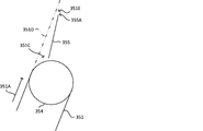
- FIG. 4 is a view showing the configuration around the peeling position of the image forming apparatus according to the first embodiment of the present invention.
- FIG. 5 is a diagram showing experimental results using the image forming apparatus according to the first embodiment of the present invention.
- FIG. 6 is a view showing an example of the arrangement of a transfer device of the image forming apparatus according to the second embodiment of the present invention.
- FIG. 7 is a view showing another example of the configuration of the transfer device of the image forming apparatus according to the second embodiment of the present invention.
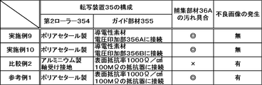
- FIG. 8 is a diagram showing experimental results using the image forming apparatus according to the second embodiment of the present invention.
- FIG. 1 is a schematic cross-sectional view showing the configuration of the image forming apparatus 10. As shown in FIG.
- the image forming apparatus 10 includes an ADF 1, an image reading unit 2, an image forming unit 3, a sheet conveyance unit 4, a control unit 5, and an operation display unit 6.
- the image forming apparatus 10 is a multifunction peripheral having a printer function for forming an image based on image data, and a plurality of functions such as a scan function, a facsimile function, or a copy function. Further, the present invention is applicable to image forming apparatuses such as a printer, a facsimile, and a copier.
- the ADF 1 is an automatic document feeder that includes a document setting unit (not shown), a plurality of transport rollers, a document pressing unit, and a paper discharge unit, and transports a document read by the image reading unit 2.
- the image reading unit 2 includes an unillustrated document table, a reading unit, a plurality of mirrors, an optical lens, and a CCD (Charge Coupled Device), and reads image data from a document.
- the control unit 5 includes control devices such as a CPU, a ROM, a RAM, and an EEPROM (not shown), and controls the operation of the image forming apparatus 10.
- the operation display unit 6 is a display unit such as a liquid crystal display that displays various types of information in response to a control instruction from the control unit 5, and operation keys or a touch panel that inputs various types of information to the control unit 5 in accordance with user operations. And the like.
- the image forming unit 3 can execute an image forming process (printing process) for forming an image by an electrophotographic method based on the image data read by the image reading unit 2.
- the image forming unit 3 can also execute image forming processing based on image data input from an information processing apparatus such as an external personal computer.
- the image forming unit 3 includes a photosensitive drum 31, a charging device 32, a light scanning device (LSU) 33, a developing device 34, a transfer device 35, a cleaning device 36, a fixing device 37, And an output tray 38. Then, in the image forming unit 3, an image is formed on the sheet supplied from the sheet conveying unit 4 in the following procedure, and the sheet after the image formation is discharged to the paper discharge tray 38.
- the sheet is a sheet material such as paper, coated paper, postcard, envelope, and OHP sheet.
- the photosensitive drum 31 is uniformly charged to a predetermined potential by the charging device 32.
- the light scanning device 33 irradiates the surface of the photosensitive drum 31 with light based on the image data.
- an electrostatic latent image corresponding to the image data is formed on the surface of the photosensitive drum 31.
- the electrostatic latent image on the photosensitive drum 31 is developed (visualized) as a toner image by the developing device 34.
- the photosensitive drum 31 is an example of the image carrier in the present invention.
- toner developer
- the toner is stirred together with the carrier inside the developing device 34, whereby it is frictionally charged, for example, to a positive polarity.
- the toner image formed on the photosensitive drum 31 is transferred onto the sheet by the transfer device 35.
- the toner image is transferred onto the sheet at a contact position 31A between the photosensitive drum 31 and the transport belt 351 of the transfer device 35 (see FIG. 3).
- the transfer device 35 will be described in detail later.
- the toner image transferred to the sheet is heated by the fixing roller 37A and melted and fixed.
- the toner remaining on the surface of the photosensitive drum 31 is removed by the cleaning device 36.
- the sheet conveying unit 4 conveys the sheet on which an image is formed by the image forming unit 3.
- the sheet conveying unit 4 includes a sheet feeding cassette 41, a pickup roller 42, a plurality of conveying roller pairs 43, and a registration roller pair 44.
- the pickup roller 42, the plurality of conveyance roller pairs 43, and the registration roller pair 44 receive the driving force generated by a motor (not shown) and rotate to convey the sheet.
- the sheet feeding cassette 41 is attachable to and detachable from the housing of the image forming apparatus 10, and accommodates the sheet on which an image is formed by the image forming unit 3.
- the sheet accommodated in the sheet feeding cassette 41 is lifted by a lift plate (not shown) provided at the bottom of the sheet feeding cassette 41 to a contact position with the pickup roller 42 provided at the top of the sheet feeding cassette 41.
- the sheet of the uppermost layer in contact with the pickup roller 42 is delivered to the conveyance path 40A by the pickup roller 42, and is conveyed in the conveyance path 40A by the conveyance roller pair 43.
- the registration roller pair 44 delivers the sheet to the contact position 31A at a predetermined timing in accordance with the arrival of the toner image formed on the photosensitive drum 31 at the contact position 31A.
- a registration sensor 40B for detecting the presence or absence of the sheet is provided on the upstream side of the pair of registration rollers 44 in the conveyance direction of the sheet in the conveyance path 40A.
- the resist sensor 40B is, for example, a transmissive or reflective optical sensor.
- the control unit 5 determines the timing based on the distance from the detection position of the sheet to the contact position 31A, the conveyance speed of the sheet, and the like. Do.
- control unit 5 controls the electromagnetic clutch (not shown) capable of switching the presence or absence of the transmission of the driving force from the motor to the registration roller pair 44, thereby rotating the registration roller pair 44 at the timing. Send out Thereby, the sheet is delivered to the contact position 31A in accordance with the arrival of the toner image formed on the photosensitive drum 31 at the contact position 31A.
- the sheet on which the toner image has been transferred by passing through the contact position 31A is transported by the fixing device 37 after the toner image is fused and fixed by passing between the fixing roller 37A and the pressure roller 37B.
- the sheet is conveyed to the discharge tray 38 by the roller pair 43 and discharged.
- the occurrence of a jam (paper jam) in the conveyance path 40A is detected.
- a plurality of sheet sensors 40C for detecting the presence or absence of the sheet are provided together with the registration sensor 40B. Then, for example, when a signal indicating detection of the sheet is not output from the registration sensor 40B or the sheet sensor 40C between the start of conveyance of the sheet and the elapse of a predetermined time, for example, the control unit 5 The occurrence of the jam is detected.
- the sheet sensor 40C is, for example, a reflective or transmissive optical sensor.
- the sheet is conveyed in a state where the sheet is electrostatically attracted to the conveyance belt 351.
- the separation of the sheet from the photosensitive drum 31, the conveyance stability of the sheet, and the improvement of the transferability of the toner image onto the sheet are realized.
- the sheet when the sheet is conveyed in a state where the sheet is electrostatically attracted to the conveyance belt 351, the sheet is conveyed by the conveyance belt 351 when the roller disposed at the peeling position where the sheet peels from the conveyance belt 351 is grounded.
- peeling discharge occurs, and the toner attached to the sheet may be scattered.
- the image forming apparatus 10 it is possible to suppress the occurrence of peeling discharge when the sheet is separated from the conveying belt 351, as described below.
- FIG. 3 is a schematic cross-sectional view showing the configuration of the transfer device 35.
- FIG. 4 is a schematic cross-sectional view showing the configuration around the peeling position 351C.
- the two-dot chain line in FIG. 4 indicates the movement path 351D of the sheet separated from the conveyance belt 351.
- the transfer device 35 electrostatically attracts and conveys the sheet delivered from the registration roller pair 44 to the conveyance belt 351, and transfers the toner image formed on the photosensitive drum 31 at the contact position 31A to the sheet.
- the transfer device 35 includes a transport belt 351, a transfer roller 352, a first roller 353, a second roller 354, a guide member 355, a voltage application unit 356 A, and a charge removing member 358.
- the conveying belt 351 contacts the photosensitive drum 31 and conveys the sheet via the contact position 31A.
- the conveyance belt 351 is an endless belt member stretched by a first roller 353 and a second roller 354 with a predetermined tension.
- the transport belt 351 is formed by coating the outer peripheral surface of a rubber belt-like member with a fluorine-based resin.
- the outer circumferential surface of the conveyance belt 351 is moved along the conveyance direction 351A as the first roller 353 or the second roller 354 is rotationally driven by a motor (not shown).
- the conveyance belt 351 can convey the sheet from the conveyance start position 351B to the peeling position 351C via the contact position 31A.
- the transfer roller 352 applies a voltage having a polarity opposite to the charge polarity of the toner forming the toner image, and transfers the toner image borne on the photosensitive drum 31 at the contact position 31A to the sheet.
- the transfer roller 352 is provided in contact with the inner peripheral surface of the transport belt 351 at the contact position 31A.
- the transfer roller 352 generates a discharge between the transfer belt 351 and the transfer belt 351 at the contact position 31A by applying a negative voltage from the voltage application unit 356A, and injects a negative charge to the transfer belt 351. Do.
- the toner image formed on the photosensitive drum 31 is attracted to the conveyance belt 351 and transferred to the sheet.
- the sheet transported by the transport belt 351 is electrostatically attracted to the outer peripheral surface of the transport belt 351 by the charge injected into the transport belt 351.
- the first roller 353 stretches the conveyance belt 351 at the conveyance start position 351 B where the conveyance of the sheet is started, which is upstream of the contact position 31 A in the conveyance direction 351 A by the conveyance belt 351.
- the first roller 353 is formed of a conductive member such as metal, and is provided to the transfer device 35 in a state of being grounded via a bearing. Therefore, part of the charge injected into the conveyance belt 351 is removed by the first roller 353.
- the second roller 354 stretches the conveyance belt 351 at a peeling position 351 C at a peeling position 351 C at which the sheet is peeled from the conveyance belt 351, which is downstream of the contact position 31 A in the conveyance direction 351 A by the conveyance belt 351.
- the second roller 354 is an example of the stretching roller in the present invention.
- the sheet and the conveyance belt 351 Peeling discharge occurs between the two.
- charge exchange is performed between the sheet and the transport belt 351 based on the positional relationship between the sheet and the materials of the transport belt 351 in a known charging sequence.
- the material of the sheet is paper and the outer peripheral surface of the conveyance belt 351 is formed of a fluorine-based resin such as PTFE, the sheet releases negative charge when it is separated from the conveyance belt 351.
- the transfer belt 351 is charged to the positive polarity, and the transport belt 351 receives the charge released from the sheet to be charged to the negative polarity. In this case, the electrostatic adhesion of the positive polarity toner attached to the sheet to the sheet is reduced, and the toner may be scattered from the sheet.
- the second roller 354 is formed of an insulator such as a synthetic resin to be in an insulating state and not grounded. As a result, the negatively charged state of the transport belt 351 at the peeling position 351C is maintained, and the movement of the negative charge from the sheet to the transport belt 351, that is, the occurrence of peeling discharge is suppressed.
- the method which makes the 2nd roller 354 an insulation state is not restricted to what was stated above.
- the second roller 354 is in an insulated state by supporting the second roller 354 by a bearing formed of an insulator and the contact portion of the second roller 354 with the rotation shaft.
- the present invention can be implemented using an existing roller member, and there is no need to separately prepare a roller member formed of an insulator.
- the guide member 355 guides the sheet separated from the conveyance belt 351 at the peeling position 351C to the fixing device 37. Specifically, as shown in FIG. 4, the guide member 355 is provided at a position facing the sheet conveyed from the second roller 354 toward the fixing device 37 along the movement path 351D. As a result, the leading end portion of the sheet in the transport direction 351A sags vertically downward by its own weight, and the movement of the sheet out of the movement path 351D is restricted. Further, in the image forming apparatus 10, the guide member 355 is disposed in a predetermined posture with respect to the movement path 351D, thereby assisting the separation operation of the sheet separated from the conveyance belt 351 by curvature separation.
- the guide member 355 is a straight line extending from the axial center of the second roller 354 toward the contact point with the second roller 354 in the movement path 351D, and from the axial center of the second roller 354 in the conveying direction 351A of the guide member 355
- the angle formed by the straight line extending toward the end is arranged to be in the range of 30 degrees or more and 60 degrees or less.
- the voltage application unit 356A applies, to the transfer roller 352, a voltage having a reverse polarity to the charging polarity of the toner.
- the voltage application unit 356A is a power supply connected to the transfer roller 352 as shown in FIG.
- the voltage application unit 356 ⁇ / b> A is controlled by the control unit 5 to apply a negative voltage to the transfer roller 352.
- the control unit 5 controls the voltage application unit 356A so that a current of -100 ⁇ A flows to the transfer roller 352.
- the charge removing member 358 is provided between the second roller 354 and a predetermined width gap as shown in FIG. 3 to remove the charge of the second roller 354.
- the charge removing member 358 is a conductive felt member grounded.
- the discharging member 358 discharges the second roller 354 by the discharge generated between the second roller 354 and the second roller 354.
- the width of the gap is appropriately set in consideration of the allowable amount of charge accumulated in the second roller 354. As a result, the excess charge exceeding the allowable amount is accumulated in the second roller 354, and the possibility of causing a malfunction of an electronic device such as the sheet sensor 40 ⁇ / b> C disposed around the second roller 354 is eliminated.
- the charge removing member 358 removes the charge of the second roller 354 and removes the charge of the conveyance belt 351 outside the contact area of the sheet on the conveyance belt 351.
- the charge removing member 358 has an inner circumferential surface of the conveyance belt 351 outside the contact area of the sheet between the conveyance start position 351B passing through the contact position 31A and the peeling position 351C. Or a gap of a predetermined width. The width of the gap is appropriately set in consideration of the charge removal performance and the like by the grounded first roller 353. As a result, the charge amount accumulated on the transport belt 351 is adjusted to an appropriate value.
- Examples 1 to 8 In the image forming apparatus 10, an experiment was conducted to investigate the scattering state of the toner at the peeling position 351C and the detection accuracy of the sheet sensor 40C by changing the configuration of the transfer device 35. The experimental results are shown in FIG. In the investigation of the scattering state of the toner in the experiment, the collecting member 36A (see FIG. 3) is provided on the outer surface opposite to the peeling position 351C of the cleaning device 36, and the image forming apparatus 10 has 50% printing ratio. The printing process for printing the experimental image data was performed 10,000 times, and the contamination condition of the collection member 36A was confirmed by the method.
- the investigation of the detection accuracy of the sheet sensor 40C in the experiment was conducted by a method of confirming the presence or absence of the erroneous detection of the jam during the execution of the printing process 10,000 times.
- “ ⁇ ” indicates that no dirt due to the toner is confirmed in the collection member 36A.
- “o” indicates that the contamination with the toner confirmed by the collection member 36A was within a predetermined allowable range.
- “x” indicates that the contamination with the toner confirmed by the collection member 36A exceeds a predetermined allowable range.
- the layer thickness at the peeling position 351C The scattering state of the toner is different. Specifically, in the case where the surface layer is the thinnest 3 ⁇ m (Example 5), the toner is easily scattered, and in the case where the surface layer is 5 ⁇ m (Example 6), the toner is less likely to be scattered. I understand. It is considered that this is because the thickness of the surface layer is insufficient and the charge accumulated on the transport belt 351 passes through the surface layer and is lost. Therefore, the surface layer of the second roller 354 is desirably 5 ⁇ m or more.
- the second roller 354 is in the insulating state, whereby the negatively charged state of the transport belt 351 at the peeling position 351C is maintained. Thereby, it is possible to suppress the occurrence of peeling discharge when the sheet is separated from the conveyance belt 351.
- the toner adhering to the sheet may scatter before the sheet is conveyed to the fixing device 37. Further, in the fixing device 37, the toner on the sheet is not fixed to the sheet and electrostatically adheres to the fixing roller 37A, causing a phenomenon called electrostatic offset which causes a defective image on the subsequent sheet. There is a risk of
- FIGS. 4, 6 and 7 are schematic cross-sectional views showing a configuration example of the transfer device 35 of the image forming apparatus 10 according to the second embodiment.
- the description of the configuration common to the image forming apparatus 10 according to the first embodiment in the image forming apparatus 10 according to the second embodiment will be omitted.
- the guide member 355 of the transfer device 35 is connected to the voltage application unit 356A via the resistor 357 in the first embodiment. This is different from the image forming apparatus 10 according to FIG.
- a voltage having a polarity opposite to the charging polarity of the toner is applied to the guide member 355.
- the guide member 355 is formed of a conductive member, and a negative voltage is applied from the voltage application unit 356A.
- a discharge is generated between the sheet conveyed from the second roller 354 toward the fixing device 37 along the movement path 351D and the guide member 355 to inject a negative charge into the sheet. Is possible. Therefore, it is possible to improve the electrostatic adhesion of the toner to the sheet.
- the guide member 355 has a gap 351E of a predetermined width between the leading end 355A of the guide member 355 and the sheet conveyed along the movement path 351D.
- the width of the gap 351E is appropriately set based on the well-known Paschen's law so that discharge occurs between the leading end 355A of the guide member 355 and the sheet.
- the gap 351E is set to 1 mm.
- the guide member 355 is provided at a position facing the surface of the sheet on the second roller 354 side. Therefore, the toner formed on the sheet by the discharge between the guide member 355 and the sheet is compared with a configuration in which the guide member 355 is provided at a position facing the surface of the sheet on which the toner image is formed. The influence on the image is suppressed.
- the voltage application unit 356A When the voltage application unit 356A applies a voltage only while the sheet passes through the contact position 31A, the rear end in the sheet conveying direction 351A is from the contact position 31A to the leading end 355A of the guide member 355. While moving, no voltage is applied to the guide member 355. Therefore, no discharge occurs between the guide member 355 and a part of the sheet. Therefore, in the image forming apparatus 10 according to the second embodiment, the voltage application unit 356A causes the trailing edge in the sheet conveyance direction 351A after the leading edge in the sheet conveyance direction 351A reaches the contact position 31A. A voltage is applied to the transfer roller 352 and the guide member 355 until the leading end 355A of the guide member 355 is released.
- the control unit 5 detects the front end of the sheet.
- the arrival timing to the contact position 31A and the separation timing from the leading end 355A of the rear end of the sheet are acquired.
- the control unit 5 measures the time from the arrival of the front end of the sheet to the contact position 31A to the separation from the front end 355A of the rear end of the sheet.
- a voltage is applied to the voltage application unit 356A. This makes it possible to generate a discharge between the entire sheet and the guide member 355.
- the resistor 357 has a resistance value higher than that of the current passage including the transfer roller 352, the conveyance belt 351, and the photosensitive drum 31.
- the resistance value of the resistor 357 is 100 M ⁇ .
- a power supply for applying a voltage to the guide member 355 may be provided separately from the voltage application unit 356A for applying a voltage to the transfer roller 352.
- the transfer device 35 applies a voltage having a polarity opposite to the charge polarity of the toner to the transfer roller 352, the voltage application unit 356A, and the guide member 355 opposite to the charge polarity of the toner.
- a configuration is conceivable that includes a voltage application unit 356B that applies a voltage of polarity.
- control unit 5 controls the voltage application unit 356A such that a current of -100 ⁇ A flows to the transfer roller 352, and controls the voltage application unit 356B so that a current of -15 ⁇ A flows to the guide member 355.
- the voltage application unit 356 B for applying a voltage to the guide member 355 is provided separately from the voltage application unit 356 A for applying a voltage to the transfer roller 352, control of the voltage applied to the guide member 355 is performed. It is possible to decouple control of the voltage applied to the transfer roller 352.
- Example 9 to 10 In the image forming apparatus 10 according to the second embodiment, an experiment was conducted to change the configuration of the transfer device 35 and investigate the scattering state of the toner and the generation state of the defective image at the peeling position 351C. The experimental results are shown in FIG.
- the method of investigating the scattering state of the toner in the experiment is the same as the experiment of the image forming apparatus 10 according to the first embodiment. Further, the investigation of the generation state of the defective image in the experiment was performed by a method of confirming the presence or absence of the generation of the defective image during the execution of the printing process of 10,000 times.
Landscapes
- Physics & Mathematics (AREA)
- General Physics & Mathematics (AREA)
- Electrostatic Charge, Transfer And Separation In Electrography (AREA)
Abstract
Description
まず、図1及び図2を参照しつつ、本発明の実施形態に係る画像形成装置10の概略構成について説明する。ここで、図1は画像形成装置10の構成を示す断面模式図である。
以下、図3及び図4を参照しつつ、転写装置35について説明する。ここで、図3は転写装置35の構成を示す断面模式図である。また、図4は剥離位置351C周辺の構成を示す断面模式図である。なお、図4における二点鎖線は、搬送ベルト351を離れた前記シートの移動経路351Dを示すものである。
画像形成装置10において、転写装置35の構成を各々変化させて、剥離位置351Cでの前記トナーの飛散状況及びシートセンサー40Cの検知精度を調査する実験を行った。実験結果を図5に示す。なお、前記実験における前記トナーの飛散状況の調査は、クリーニング装置36の剥離位置351Cに対向する外側面に捕集部材36A(図3参照)を設けて、画像形成装置10に印字率50パーセントの実験用の画像データを印刷する前記印刷処理を1万回実行させた後の捕集部材36Aの汚れ具合を確認する方法により行った。また、前記実験におけるシートセンサー40Cの検知精度の調査は、1万回の前記印刷処理の実行中における前記ジャムの誤検出の有無を確認する方法により行った。ここで、図5において、「◎」は捕集部材36Aで前記トナーによる汚れが確認されなかったことを示すものである。また、「○」は捕集部材36Aで確認された前記トナーによる汚れが予め定められた許容範囲内であったことを示すものである。また、「×」は捕集部材36Aで確認された前記トナーによる汚れが予め定められた許容範囲を超えていたことを示すものである。
ところで、前記シートに対する前記トナーの静電的な付着力が弱い場合には、前記シートが定着装置37に搬送されるまでの間に、前記シートに付着した前記トナーが飛散するおそれがある。また、定着装置37において前記シート上の前記トナーが前記シートに定着されずに定着ローラー37Aに静電的に付着して、後続の前記シートに不良画像を生じさせる静電オフセットと呼ばれる現象が発生するおそれがある。
前記第2実施形態に係る画像形成装置10において、転写装置35の構成を各々変化させて、剥離位置351Cでの前記トナーの飛散状況及び不良画像の発生状況を調査する実験を行った。実験結果を図8に示す。なお、前記実験における前記トナーの飛散状況の調査方法は、前記第1実施形態に係る画像形成装置10についての前記実験と同様である。また、前記実験における不良画像の発生状況の調査は、1万回の前記印刷処理の実行中における不良画像の発生の有無を確認する方法により行った。
Claims (8)
- トナー像を担持する像担持体と接触し、前記像担持体との接触位置を経由してシートを搬送する搬送ベルトと、
前記トナー像を形成するトナーの帯電極性と逆極性の電圧が印加され、前記接触位置において前記像担持体に担持された前記トナー像を前記シートに転写させる転写ローラーと、
前記搬送ベルトによる前記シートの搬送方向において前記接触位置より下流側であって前記シートが前記搬送ベルトから剥離する剥離位置において前記搬送ベルトを張架する絶縁状態の張架ローラーと、
を備える転写装置。 - 前記張架ローラーとの間に予め定められた幅の間隙を介して設けられ、前記張架ローラーを除電する除電部材を更に備える請求項1に記載の転写装置。
- 前記除電部材が、前記張架ローラーを除電すると共に前記搬送ベルトにおける前記シートの接触領域外で前記搬送ベルトを除電する請求項2に記載の転写装置。
- 前記張架ローラーが絶縁体で形成されている請求項1に記載の転写装置。
- 前記張架ローラーが、前記張架ローラーの回転軸との接触部が絶縁体で形成された軸受けによって支持されている請求項1に記載の転写装置。
- 前記張架ローラーの表層が絶縁体で形成されている請求項1に記載の転写装置。
- 前記表層が5μm以上の層厚を有する請求項6に記載の転写装置。
- 請求項1に記載の転写装置を備える画像形成装置。
Priority Applications (3)
| Application Number | Priority Date | Filing Date | Title |
|---|---|---|---|
| JP2016531229A JP6091714B2 (ja) | 2014-06-30 | 2015-06-12 | 転写装置、画像形成装置 |
| US14/915,155 US9513581B2 (en) | 2014-06-30 | 2015-06-12 | Transfer device, image forming apparatus |
| CN201580001579.6A CN105474105B (zh) | 2014-06-30 | 2015-06-12 | 转印装置和图像形成装置 |
Applications Claiming Priority (2)
| Application Number | Priority Date | Filing Date | Title |
|---|---|---|---|
| JP2014133692 | 2014-06-30 | ||
| JP2014-133692 | 2014-06-30 |
Publications (1)
| Publication Number | Publication Date |
|---|---|
| WO2016002474A1 true WO2016002474A1 (ja) | 2016-01-07 |
Family
ID=55019021
Family Applications (1)
| Application Number | Title | Priority Date | Filing Date |
|---|---|---|---|
| PCT/JP2015/066972 Ceased WO2016002474A1 (ja) | 2014-06-30 | 2015-06-12 | 転写装置、画像形成装置 |
Country Status (4)
| Country | Link |
|---|---|
| US (1) | US9513581B2 (ja) |
| JP (1) | JP6091714B2 (ja) |
| CN (1) | CN105474105B (ja) |
| WO (1) | WO2016002474A1 (ja) |
Families Citing this family (5)
| Publication number | Priority date | Publication date | Assignee | Title |
|---|---|---|---|---|
| JP2019169410A (ja) * | 2018-03-26 | 2019-10-03 | コニカミノルタ株式会社 | 帯電調整装置及び画像形成装置 |
| JP7040263B2 (ja) * | 2018-04-26 | 2022-03-23 | 京セラドキュメントソリューションズ株式会社 | 定着装置及び画像形成装置 |
| US10915043B2 (en) * | 2018-09-04 | 2021-02-09 | Fuji Xerox Co., Ltd. | Image forming apparatus |
| EP3745209B1 (en) * | 2019-05-30 | 2022-11-30 | KYOCERA Document Solutions Inc. | Cleaning device and image forming apparatus including the same |
| JP7501022B2 (ja) * | 2020-03-19 | 2024-06-18 | 富士フイルムビジネスイノベーション株式会社 | 画像形成装置 |
Citations (5)
| Publication number | Priority date | Publication date | Assignee | Title |
|---|---|---|---|---|
| JPH11167289A (ja) * | 1997-09-30 | 1999-06-22 | Canon Inc | 画像形成装置 |
| JPH11344871A (ja) * | 1998-05-29 | 1999-12-14 | Canon Inc | 画像形成装置 |
| JP2001272869A (ja) * | 2000-01-20 | 2001-10-05 | Ricoh Co Ltd | 画像形成装置 |
| JP2002099161A (ja) * | 1992-01-22 | 2002-04-05 | Ricoh Co Ltd | 画像形成装置の転写装置 |
| JP2005338562A (ja) * | 2004-05-28 | 2005-12-08 | Canon Inc | 画像形成装置、制御方法およびプログラム |
Family Cites Families (9)
| Publication number | Priority date | Publication date | Assignee | Title |
|---|---|---|---|---|
| US5461461A (en) | 1992-01-22 | 1995-10-24 | Ricoh Company, Ltd. | Image transferring device and medium separating device for an image forming apparatus |
| JP3245240B2 (ja) * | 1992-01-22 | 2002-01-07 | 株式会社リコー | 画像形成装置の転写装置 |
| US5659843A (en) * | 1992-01-22 | 1997-08-19 | Ricoh Company, Ltd. | Image transferring device for image forming equipment |
| JP3356231B2 (ja) * | 1994-01-24 | 2002-12-16 | 株式会社リコー | 転写搬送装置 |
| JP4215379B2 (ja) | 2000-07-18 | 2009-01-28 | 株式会社リコー | 転写搬送装置及び画像形成装置 |
| JP4569401B2 (ja) * | 2005-06-21 | 2010-10-27 | 富士ゼロックス株式会社 | 画像形成装置 |
| JP2008164903A (ja) * | 2006-12-28 | 2008-07-17 | Kyocera Mita Corp | 定着装置及び画像形成装置 |
| CN105474106A (zh) * | 2014-06-30 | 2016-04-06 | 京瓷办公信息系统株式会社 | 转印装置和图像形成装置 |
| JP6265066B2 (ja) * | 2014-06-30 | 2018-01-24 | 京セラドキュメントソリューションズ株式会社 | 転写装置、画像形成装置 |
-
2015
- 2015-06-12 US US14/915,155 patent/US9513581B2/en not_active Expired - Fee Related
- 2015-06-12 JP JP2016531229A patent/JP6091714B2/ja not_active Expired - Fee Related
- 2015-06-12 CN CN201580001579.6A patent/CN105474105B/zh not_active Expired - Fee Related
- 2015-06-12 WO PCT/JP2015/066972 patent/WO2016002474A1/ja not_active Ceased
Patent Citations (5)
| Publication number | Priority date | Publication date | Assignee | Title |
|---|---|---|---|---|
| JP2002099161A (ja) * | 1992-01-22 | 2002-04-05 | Ricoh Co Ltd | 画像形成装置の転写装置 |
| JPH11167289A (ja) * | 1997-09-30 | 1999-06-22 | Canon Inc | 画像形成装置 |
| JPH11344871A (ja) * | 1998-05-29 | 1999-12-14 | Canon Inc | 画像形成装置 |
| JP2001272869A (ja) * | 2000-01-20 | 2001-10-05 | Ricoh Co Ltd | 画像形成装置 |
| JP2005338562A (ja) * | 2004-05-28 | 2005-12-08 | Canon Inc | 画像形成装置、制御方法およびプログラム |
Also Published As
| Publication number | Publication date |
|---|---|
| US20160209785A1 (en) | 2016-07-21 |
| US9513581B2 (en) | 2016-12-06 |
| JPWO2016002474A1 (ja) | 2017-04-27 |
| JP6091714B2 (ja) | 2017-03-08 |
| CN105474105A (zh) | 2016-04-06 |
| CN105474105B (zh) | 2019-02-05 |
Similar Documents
| Publication | Publication Date | Title |
|---|---|---|
| JP6091714B2 (ja) | 転写装置、画像形成装置 | |
| JP6265066B2 (ja) | 転写装置、画像形成装置 | |
| US9442433B2 (en) | Image forming apparatus | |
| JP6161818B2 (ja) | 転写装置、画像形成装置 | |
| WO2010122745A1 (ja) | 画像形成装置 | |
| JP2006195193A (ja) | 画像形成装置の転写材搬送ガイド機構 | |
| JP6304496B2 (ja) | 画像形成装置 | |
| JP2010085799A (ja) | 画像形成装置及び定着装置 | |
| JP6288463B2 (ja) | 画像形成装置 | |
| JP6233604B2 (ja) | 画像形成装置 | |
| JP2014240903A (ja) | 画像形成装置 | |
| JP5268311B2 (ja) | 画像形成装置 | |
| JP5184169B2 (ja) | 画像形成装置 | |
| US9612563B2 (en) | Image forming apparatus that restrains scattered toner particles | |
| JP6380758B2 (ja) | 画像形成装置 | |
| JP6736358B2 (ja) | 画像形成装置 | |
| US10139758B2 (en) | Transfer device allowing suppression of occurrence of separation discharge between sheets, and image forming apparatus | |
| JP2004252061A (ja) | 画像形成装置 | |
| JP6021709B2 (ja) | 画像形成装置 | |
| JP2002091182A (ja) | 画像形成装置 | |
| JP2012098364A (ja) | 画像形成装置 | |
| JP2008058422A (ja) | 画像形成装置 | |
| JP2004045661A (ja) | 画像形成装置 |
Legal Events
| Date | Code | Title | Description |
|---|---|---|---|
| WWE | Wipo information: entry into national phase |
Ref document number: 201580001579.6 Country of ref document: CN |
|
| ENP | Entry into the national phase |
Ref document number: 2016531229 Country of ref document: JP Kind code of ref document: A |
|
| 121 | Ep: the epo has been informed by wipo that ep was designated in this application |
Ref document number: 15814273 Country of ref document: EP Kind code of ref document: A1 |
|
| WWE | Wipo information: entry into national phase |
Ref document number: 14915155 Country of ref document: US |
|
| NENP | Non-entry into the national phase |
Ref country code: DE |
|
| 122 | Ep: pct application non-entry in european phase |
Ref document number: 15814273 Country of ref document: EP Kind code of ref document: A1 |