WO2016002456A1 - 積層体および一体化成形品 - Google Patents
積層体および一体化成形品 Download PDFInfo
- Publication number
- WO2016002456A1 WO2016002456A1 PCT/JP2015/066803 JP2015066803W WO2016002456A1 WO 2016002456 A1 WO2016002456 A1 WO 2016002456A1 JP 2015066803 W JP2015066803 W JP 2015066803W WO 2016002456 A1 WO2016002456 A1 WO 2016002456A1
- Authority
- WO
- WIPO (PCT)
- Prior art keywords
- radio wave
- laminate
- region
- fiber reinforced
- reinforced plastic
- Prior art date
Links
Images


Classifications
-
- G—PHYSICS
- G06—COMPUTING; CALCULATING OR COUNTING
- G06F—ELECTRIC DIGITAL DATA PROCESSING
- G06F1/00—Details not covered by groups G06F3/00 - G06F13/00 and G06F21/00
- G06F1/16—Constructional details or arrangements
- G06F1/1613—Constructional details or arrangements for portable computers
- G06F1/1633—Constructional details or arrangements of portable computers not specific to the type of enclosures covered by groups G06F1/1615 - G06F1/1626
- G06F1/1656—Details related to functional adaptations of the enclosure, e.g. to provide protection against EMI, shock, water, or to host detachable peripherals like a mouse or removable expansions units like PCMCIA cards, or to provide access to internal components for maintenance or to removable storage supports like CDs or DVDs, or to mechanically mount accessories
-
- B—PERFORMING OPERATIONS; TRANSPORTING
- B32—LAYERED PRODUCTS
- B32B—LAYERED PRODUCTS, i.e. PRODUCTS BUILT-UP OF STRATA OF FLAT OR NON-FLAT, e.g. CELLULAR OR HONEYCOMB, FORM
- B32B15/00—Layered products comprising a layer of metal
- B32B15/04—Layered products comprising a layer of metal comprising metal as the main or only constituent of a layer, which is next to another layer of the same or of a different material
- B32B15/08—Layered products comprising a layer of metal comprising metal as the main or only constituent of a layer, which is next to another layer of the same or of a different material of synthetic resin
- B32B15/085—Layered products comprising a layer of metal comprising metal as the main or only constituent of a layer, which is next to another layer of the same or of a different material of synthetic resin comprising polyolefins
-
- B—PERFORMING OPERATIONS; TRANSPORTING
- B32—LAYERED PRODUCTS
- B32B—LAYERED PRODUCTS, i.e. PRODUCTS BUILT-UP OF STRATA OF FLAT OR NON-FLAT, e.g. CELLULAR OR HONEYCOMB, FORM
- B32B15/00—Layered products comprising a layer of metal
- B32B15/14—Layered products comprising a layer of metal next to a fibrous or filamentary layer
-
- B—PERFORMING OPERATIONS; TRANSPORTING
- B32—LAYERED PRODUCTS
- B32B—LAYERED PRODUCTS, i.e. PRODUCTS BUILT-UP OF STRATA OF FLAT OR NON-FLAT, e.g. CELLULAR OR HONEYCOMB, FORM
- B32B15/00—Layered products comprising a layer of metal
- B32B15/18—Layered products comprising a layer of metal comprising iron or steel
-
- B—PERFORMING OPERATIONS; TRANSPORTING
- B32—LAYERED PRODUCTS
- B32B—LAYERED PRODUCTS, i.e. PRODUCTS BUILT-UP OF STRATA OF FLAT OR NON-FLAT, e.g. CELLULAR OR HONEYCOMB, FORM
- B32B15/00—Layered products comprising a layer of metal
- B32B15/20—Layered products comprising a layer of metal comprising aluminium or copper
-
- B—PERFORMING OPERATIONS; TRANSPORTING
- B32—LAYERED PRODUCTS
- B32B—LAYERED PRODUCTS, i.e. PRODUCTS BUILT-UP OF STRATA OF FLAT OR NON-FLAT, e.g. CELLULAR OR HONEYCOMB, FORM
- B32B27/00—Layered products comprising a layer of synthetic resin
- B32B27/06—Layered products comprising a layer of synthetic resin as the main or only constituent of a layer, which is next to another layer of the same or of a different material
- B32B27/08—Layered products comprising a layer of synthetic resin as the main or only constituent of a layer, which is next to another layer of the same or of a different material of synthetic resin
-
- B—PERFORMING OPERATIONS; TRANSPORTING
- B32—LAYERED PRODUCTS
- B32B—LAYERED PRODUCTS, i.e. PRODUCTS BUILT-UP OF STRATA OF FLAT OR NON-FLAT, e.g. CELLULAR OR HONEYCOMB, FORM
- B32B27/00—Layered products comprising a layer of synthetic resin
- B32B27/32—Layered products comprising a layer of synthetic resin comprising polyolefins
-
- B—PERFORMING OPERATIONS; TRANSPORTING
- B32—LAYERED PRODUCTS
- B32B—LAYERED PRODUCTS, i.e. PRODUCTS BUILT-UP OF STRATA OF FLAT OR NON-FLAT, e.g. CELLULAR OR HONEYCOMB, FORM
- B32B5/00—Layered products characterised by the non- homogeneity or physical structure, i.e. comprising a fibrous, filamentary, particulate or foam layer; Layered products characterised by having a layer differing constitutionally or physically in different parts
- B32B5/02—Layered products characterised by the non- homogeneity or physical structure, i.e. comprising a fibrous, filamentary, particulate or foam layer; Layered products characterised by having a layer differing constitutionally or physically in different parts characterised by structural features of a fibrous or filamentary layer
- B32B5/12—Layered products characterised by the non- homogeneity or physical structure, i.e. comprising a fibrous, filamentary, particulate or foam layer; Layered products characterised by having a layer differing constitutionally or physically in different parts characterised by structural features of a fibrous or filamentary layer characterised by the relative arrangement of fibres or filaments of different layers, e.g. the fibres or filaments being parallel or perpendicular to each other
-
- B—PERFORMING OPERATIONS; TRANSPORTING
- B32—LAYERED PRODUCTS
- B32B—LAYERED PRODUCTS, i.e. PRODUCTS BUILT-UP OF STRATA OF FLAT OR NON-FLAT, e.g. CELLULAR OR HONEYCOMB, FORM
- B32B5/00—Layered products characterised by the non- homogeneity or physical structure, i.e. comprising a fibrous, filamentary, particulate or foam layer; Layered products characterised by having a layer differing constitutionally or physically in different parts
- B32B5/22—Layered products characterised by the non- homogeneity or physical structure, i.e. comprising a fibrous, filamentary, particulate or foam layer; Layered products characterised by having a layer differing constitutionally or physically in different parts characterised by the presence of two or more layers which are next to each other and are fibrous, filamentary, formed of particles or foamed
- B32B5/24—Layered products characterised by the non- homogeneity or physical structure, i.e. comprising a fibrous, filamentary, particulate or foam layer; Layered products characterised by having a layer differing constitutionally or physically in different parts characterised by the presence of two or more layers which are next to each other and are fibrous, filamentary, formed of particles or foamed one layer being a fibrous or filamentary layer
- B32B5/26—Layered products characterised by the non- homogeneity or physical structure, i.e. comprising a fibrous, filamentary, particulate or foam layer; Layered products characterised by having a layer differing constitutionally or physically in different parts characterised by the presence of two or more layers which are next to each other and are fibrous, filamentary, formed of particles or foamed one layer being a fibrous or filamentary layer another layer next to it also being fibrous or filamentary
-
- B—PERFORMING OPERATIONS; TRANSPORTING
- B32—LAYERED PRODUCTS
- B32B—LAYERED PRODUCTS, i.e. PRODUCTS BUILT-UP OF STRATA OF FLAT OR NON-FLAT, e.g. CELLULAR OR HONEYCOMB, FORM
- B32B7/00—Layered products characterised by the relation between layers; Layered products characterised by the relative orientation of features between layers, or by the relative values of a measurable parameter between layers, i.e. products comprising layers having different physical, chemical or physicochemical properties; Layered products characterised by the interconnection of layers
- B32B7/02—Physical, chemical or physicochemical properties
- B32B7/022—Mechanical properties
-
- B—PERFORMING OPERATIONS; TRANSPORTING
- B32—LAYERED PRODUCTS
- B32B—LAYERED PRODUCTS, i.e. PRODUCTS BUILT-UP OF STRATA OF FLAT OR NON-FLAT, e.g. CELLULAR OR HONEYCOMB, FORM
- B32B7/00—Layered products characterised by the relation between layers; Layered products characterised by the relative orientation of features between layers, or by the relative values of a measurable parameter between layers, i.e. products comprising layers having different physical, chemical or physicochemical properties; Layered products characterised by the interconnection of layers
- B32B7/02—Physical, chemical or physicochemical properties
- B32B7/025—Electric or magnetic properties
-
- B—PERFORMING OPERATIONS; TRANSPORTING
- B32—LAYERED PRODUCTS
- B32B—LAYERED PRODUCTS, i.e. PRODUCTS BUILT-UP OF STRATA OF FLAT OR NON-FLAT, e.g. CELLULAR OR HONEYCOMB, FORM
- B32B7/00—Layered products characterised by the relation between layers; Layered products characterised by the relative orientation of features between layers, or by the relative values of a measurable parameter between layers, i.e. products comprising layers having different physical, chemical or physicochemical properties; Layered products characterised by the interconnection of layers
- B32B7/04—Interconnection of layers
- B32B7/12—Interconnection of layers using interposed adhesives or interposed materials with bonding properties
-
- G—PHYSICS
- G06—COMPUTING; CALCULATING OR COUNTING
- G06F—ELECTRIC DIGITAL DATA PROCESSING
- G06F1/00—Details not covered by groups G06F3/00 - G06F13/00 and G06F21/00
- G06F1/16—Constructional details or arrangements
- G06F1/1613—Constructional details or arrangements for portable computers
- G06F1/1633—Constructional details or arrangements of portable computers not specific to the type of enclosures covered by groups G06F1/1615 - G06F1/1626
- G06F1/1684—Constructional details or arrangements related to integrated I/O peripherals not covered by groups G06F1/1635 - G06F1/1675
- G06F1/1698—Constructional details or arrangements related to integrated I/O peripherals not covered by groups G06F1/1635 - G06F1/1675 the I/O peripheral being a sending/receiving arrangement to establish a cordless communication link, e.g. radio or infrared link, integrated cellular phone
-
- G—PHYSICS
- G06—COMPUTING; CALCULATING OR COUNTING
- G06F—ELECTRIC DIGITAL DATA PROCESSING
- G06F1/00—Details not covered by groups G06F3/00 - G06F13/00 and G06F21/00
- G06F1/16—Constructional details or arrangements
- G06F1/20—Cooling means
-
- H—ELECTRICITY
- H01—ELECTRIC ELEMENTS
- H01Q—ANTENNAS, i.e. RADIO AERIALS
- H01Q1/00—Details of, or arrangements associated with, antennas
- H01Q1/52—Means for reducing coupling between antennas; Means for reducing coupling between an antenna and another structure
- H01Q1/526—Electromagnetic shields
-
- H—ELECTRICITY
- H01—ELECTRIC ELEMENTS
- H01Q—ANTENNAS, i.e. RADIO AERIALS
- H01Q17/00—Devices for absorbing waves radiated from an antenna; Combinations of such devices with active antenna elements or systems
-
- H—ELECTRICITY
- H04—ELECTRIC COMMUNICATION TECHNIQUE
- H04B—TRANSMISSION
- H04B1/00—Details of transmission systems, not covered by a single one of groups H04B3/00 - H04B13/00; Details of transmission systems not characterised by the medium used for transmission
- H04B1/38—Transceivers, i.e. devices in which transmitter and receiver form a structural unit and in which at least one part is used for functions of transmitting and receiving
- H04B1/3827—Portable transceivers
- H04B1/3833—Hand-held transceivers
- H04B1/3838—Arrangements for reducing RF exposure to the user, e.g. by changing the shape of the transceiver while in use
-
- H—ELECTRICITY
- H05—ELECTRIC TECHNIQUES NOT OTHERWISE PROVIDED FOR
- H05K—PRINTED CIRCUITS; CASINGS OR CONSTRUCTIONAL DETAILS OF ELECTRIC APPARATUS; MANUFACTURE OF ASSEMBLAGES OF ELECTRICAL COMPONENTS
- H05K7/00—Constructional details common to different types of electric apparatus
- H05K7/20—Modifications to facilitate cooling, ventilating, or heating
- H05K7/2039—Modifications to facilitate cooling, ventilating, or heating characterised by the heat transfer by conduction from the heat generating element to a dissipating body
- H05K7/20436—Inner thermal coupling elements in heat dissipating housings, e.g. protrusions or depressions integrally formed in the housing
- H05K7/20445—Inner thermal coupling elements in heat dissipating housings, e.g. protrusions or depressions integrally formed in the housing the coupling element being an additional piece, e.g. thermal standoff
- H05K7/20472—Sheet interfaces
- H05K7/20481—Sheet interfaces characterised by the material composition exhibiting specific thermal properties
-
- H—ELECTRICITY
- H05—ELECTRIC TECHNIQUES NOT OTHERWISE PROVIDED FOR
- H05K—PRINTED CIRCUITS; CASINGS OR CONSTRUCTIONAL DETAILS OF ELECTRIC APPARATUS; MANUFACTURE OF ASSEMBLAGES OF ELECTRICAL COMPONENTS
- H05K9/00—Screening of apparatus or components against electric or magnetic fields
- H05K9/0073—Shielding materials
- H05K9/0081—Electromagnetic shielding materials, e.g. EMI, RFI shielding
- H05K9/009—Electromagnetic shielding materials, e.g. EMI, RFI shielding comprising electro-conductive fibres, e.g. metal fibres, carbon fibres, metallised textile fibres, electro-conductive mesh, woven, non-woven mat, fleece, cross-linked
-
- B—PERFORMING OPERATIONS; TRANSPORTING
- B32—LAYERED PRODUCTS
- B32B—LAYERED PRODUCTS, i.e. PRODUCTS BUILT-UP OF STRATA OF FLAT OR NON-FLAT, e.g. CELLULAR OR HONEYCOMB, FORM
- B32B2250/00—Layers arrangement
- B32B2250/44—Number of layers variable across the laminate
-
- B—PERFORMING OPERATIONS; TRANSPORTING
- B32—LAYERED PRODUCTS
- B32B—LAYERED PRODUCTS, i.e. PRODUCTS BUILT-UP OF STRATA OF FLAT OR NON-FLAT, e.g. CELLULAR OR HONEYCOMB, FORM
- B32B2260/00—Layered product comprising an impregnated, embedded, or bonded layer wherein the layer comprises an impregnation, embedding, or binder material
- B32B2260/02—Composition of the impregnated, bonded or embedded layer
- B32B2260/021—Fibrous or filamentary layer
- B32B2260/023—Two or more layers
-
- B—PERFORMING OPERATIONS; TRANSPORTING
- B32—LAYERED PRODUCTS
- B32B—LAYERED PRODUCTS, i.e. PRODUCTS BUILT-UP OF STRATA OF FLAT OR NON-FLAT, e.g. CELLULAR OR HONEYCOMB, FORM
- B32B2260/00—Layered product comprising an impregnated, embedded, or bonded layer wherein the layer comprises an impregnation, embedding, or binder material
- B32B2260/04—Impregnation, embedding, or binder material
- B32B2260/046—Synthetic resin
-
- B—PERFORMING OPERATIONS; TRANSPORTING
- B32—LAYERED PRODUCTS
- B32B—LAYERED PRODUCTS, i.e. PRODUCTS BUILT-UP OF STRATA OF FLAT OR NON-FLAT, e.g. CELLULAR OR HONEYCOMB, FORM
- B32B2262/00—Composition or structural features of fibres which form a fibrous or filamentary layer or are present as additives
- B32B2262/02—Synthetic macromolecular fibres
- B32B2262/0246—Acrylic resin fibres
-
- B—PERFORMING OPERATIONS; TRANSPORTING
- B32—LAYERED PRODUCTS
- B32B—LAYERED PRODUCTS, i.e. PRODUCTS BUILT-UP OF STRATA OF FLAT OR NON-FLAT, e.g. CELLULAR OR HONEYCOMB, FORM
- B32B2262/00—Composition or structural features of fibres which form a fibrous or filamentary layer or are present as additives
- B32B2262/02—Synthetic macromolecular fibres
- B32B2262/0253—Polyolefin fibres
-
- B—PERFORMING OPERATIONS; TRANSPORTING
- B32—LAYERED PRODUCTS
- B32B—LAYERED PRODUCTS, i.e. PRODUCTS BUILT-UP OF STRATA OF FLAT OR NON-FLAT, e.g. CELLULAR OR HONEYCOMB, FORM
- B32B2262/00—Composition or structural features of fibres which form a fibrous or filamentary layer or are present as additives
- B32B2262/02—Synthetic macromolecular fibres
- B32B2262/0261—Polyamide fibres
- B32B2262/0269—Aromatic polyamide fibres
-
- B—PERFORMING OPERATIONS; TRANSPORTING
- B32—LAYERED PRODUCTS
- B32B—LAYERED PRODUCTS, i.e. PRODUCTS BUILT-UP OF STRATA OF FLAT OR NON-FLAT, e.g. CELLULAR OR HONEYCOMB, FORM
- B32B2262/00—Composition or structural features of fibres which form a fibrous or filamentary layer or are present as additives
- B32B2262/02—Synthetic macromolecular fibres
- B32B2262/0276—Polyester fibres
-
- B—PERFORMING OPERATIONS; TRANSPORTING
- B32—LAYERED PRODUCTS
- B32B—LAYERED PRODUCTS, i.e. PRODUCTS BUILT-UP OF STRATA OF FLAT OR NON-FLAT, e.g. CELLULAR OR HONEYCOMB, FORM
- B32B2262/00—Composition or structural features of fibres which form a fibrous or filamentary layer or are present as additives
- B32B2262/10—Inorganic fibres
- B32B2262/101—Glass fibres
-
- B—PERFORMING OPERATIONS; TRANSPORTING
- B32—LAYERED PRODUCTS
- B32B—LAYERED PRODUCTS, i.e. PRODUCTS BUILT-UP OF STRATA OF FLAT OR NON-FLAT, e.g. CELLULAR OR HONEYCOMB, FORM
- B32B2262/00—Composition or structural features of fibres which form a fibrous or filamentary layer or are present as additives
- B32B2262/10—Inorganic fibres
- B32B2262/103—Metal fibres
-
- B—PERFORMING OPERATIONS; TRANSPORTING
- B32—LAYERED PRODUCTS
- B32B—LAYERED PRODUCTS, i.e. PRODUCTS BUILT-UP OF STRATA OF FLAT OR NON-FLAT, e.g. CELLULAR OR HONEYCOMB, FORM
- B32B2262/00—Composition or structural features of fibres which form a fibrous or filamentary layer or are present as additives
- B32B2262/10—Inorganic fibres
- B32B2262/105—Ceramic fibres
-
- B—PERFORMING OPERATIONS; TRANSPORTING
- B32—LAYERED PRODUCTS
- B32B—LAYERED PRODUCTS, i.e. PRODUCTS BUILT-UP OF STRATA OF FLAT OR NON-FLAT, e.g. CELLULAR OR HONEYCOMB, FORM
- B32B2262/00—Composition or structural features of fibres which form a fibrous or filamentary layer or are present as additives
- B32B2262/10—Inorganic fibres
- B32B2262/106—Carbon fibres, e.g. graphite fibres
-
- B—PERFORMING OPERATIONS; TRANSPORTING
- B32—LAYERED PRODUCTS
- B32B—LAYERED PRODUCTS, i.e. PRODUCTS BUILT-UP OF STRATA OF FLAT OR NON-FLAT, e.g. CELLULAR OR HONEYCOMB, FORM
- B32B2307/00—Properties of the layers or laminate
- B32B2307/20—Properties of the layers or laminate having particular electrical or magnetic properties, e.g. piezoelectric
- B32B2307/206—Insulating
-
- B—PERFORMING OPERATIONS; TRANSPORTING
- B32—LAYERED PRODUCTS
- B32B—LAYERED PRODUCTS, i.e. PRODUCTS BUILT-UP OF STRATA OF FLAT OR NON-FLAT, e.g. CELLULAR OR HONEYCOMB, FORM
- B32B2307/00—Properties of the layers or laminate
- B32B2307/20—Properties of the layers or laminate having particular electrical or magnetic properties, e.g. piezoelectric
- B32B2307/212—Electromagnetic interference shielding
-
- B—PERFORMING OPERATIONS; TRANSPORTING
- B32—LAYERED PRODUCTS
- B32B—LAYERED PRODUCTS, i.e. PRODUCTS BUILT-UP OF STRATA OF FLAT OR NON-FLAT, e.g. CELLULAR OR HONEYCOMB, FORM
- B32B2307/00—Properties of the layers or laminate
- B32B2307/30—Properties of the layers or laminate having particular thermal properties
- B32B2307/302—Conductive
-
- B—PERFORMING OPERATIONS; TRANSPORTING
- B32—LAYERED PRODUCTS
- B32B—LAYERED PRODUCTS, i.e. PRODUCTS BUILT-UP OF STRATA OF FLAT OR NON-FLAT, e.g. CELLULAR OR HONEYCOMB, FORM
- B32B2307/00—Properties of the layers or laminate
- B32B2307/50—Properties of the layers or laminate having particular mechanical properties
- B32B2307/546—Flexural strength; Flexion stiffness
-
- B—PERFORMING OPERATIONS; TRANSPORTING
- B32—LAYERED PRODUCTS
- B32B—LAYERED PRODUCTS, i.e. PRODUCTS BUILT-UP OF STRATA OF FLAT OR NON-FLAT, e.g. CELLULAR OR HONEYCOMB, FORM
- B32B2307/00—Properties of the layers or laminate
- B32B2307/70—Other properties
-
- B—PERFORMING OPERATIONS; TRANSPORTING
- B32—LAYERED PRODUCTS
- B32B—LAYERED PRODUCTS, i.e. PRODUCTS BUILT-UP OF STRATA OF FLAT OR NON-FLAT, e.g. CELLULAR OR HONEYCOMB, FORM
- B32B2457/00—Electrical equipment
Definitions
- the present invention relates to a laminate and an integrally molded product formed of a fiber reinforced plastic or the like, which is used as a part or casing part of a personal computer, an OA device, a mobile phone, or the like.
- electric and electronic devices such as personal computers, OA devices, AV devices, mobile phones, telephones, facsimiles, home appliances, and toy products are required to be smaller and lighter as their portability increases.
- the parts that make up the equipment, especially the case have high strength and strength so that the case will not bend greatly when it is loaded from the outside, causing contact with internal parts and destruction. Thinning is required while satisfying high rigidity.
- radio wave blocking performance that is, a radio wave blocking (EMI) blocking function.
- EMI radio wave blocking
- antennas for wireless communication are mounted on many notebook PCs, mobile phones, or tablet products, but in most cases, antennas are arranged inside the housing from the viewpoint of portability and design.
- a material with high electromagnetic shielding properties such as carbon fiber reinforced plastic or magnesium alloy, is selected for the entire casing of such a device, the average antenna gain is reduced or biased by the case with high radio wave shielding performance.
- radio directivity has been developed and the wireless communication performance has deteriorated.
- Patent Document 1 discloses a radio wave shielding material made of a fiber reinforced resin, and a radio wave transmitting material made of a fiber reinforced thermoplastic resin containing a certain amount of non-conductive reinforced fibers in a thermoplastic resin.
- an outsert injection molding is used to place the thermoplastic resin adhesive layer at the adhesive interface between the radio wave shield material and the radio wave transparent material.
- the thickness of the previously set radio wave shielding material is unchanged before and after molding, the thicknesses of the two radio wave shielding material and radio wave transmitting material are uniformly adjusted during molding. It is difficult to do this, and a step is generated in the joint portion of the obtained molded product. For example, when the molded product is coated, the joint line is visually recognized, which has a great influence on the design.
- the radio wave transmitting material used for the radio wave transmitting region for obtaining wireless communication performance is an insulating material, and the insulating material generally has a large molding shrinkage. There has been a problem that the housing tends to warp or deform due to the difference in molding shrinkage after molding.
- Patent Document 2 discloses a molding material base (A) containing conductive fibers as reinforcing fibers, a thermoplastic resin as a matrix, insulating fibers as reinforcing fibers, and a molding material base containing a thermoplastic resin as a matrix.
- the material (B) is arranged so that the molding material base (B) is inserted in the thickness direction to form a plate-shaped molding precursor, and the molding precursor is higher than the melting temperature of the thermoplastic resin.
- Patent Document 2 it is necessary to punch out a portion where the radio wave transmission region is to be formed in advance in the molding material base (A), and is dimensionally compatible with the punched-out portion. Since it is necessary to separately prepare a molding material base material (B) having a highly accurate shape, a casing having a radio wave transmission region can be produced by using an insulating base material in part. The manufacturing process becomes complicated, and problems remain in production costs.
- Patent Document 3 discloses a composite base material in which a first reinforced base material, which is a sheet-like paper having conductive discontinuous reinforcing fibers, and a second base material different from the first base material are butt-joined.
- a pre-molding laminate in which a matrix resin sheet containing a thermoplastic resin as a main component is laminated in at least a part of a layer between at least a plurality of substrate laminates, and placing the pre-molding laminate in a pair of molds
- the matrix resin that was in the form of a sheet is impregnated into the laminate before molding, then cooled and shaped in the mold to integrate
- a technique for obtaining a composite laminate having a part of a radio wave transmission region that is excellent in design and does not deteriorate radio communication performance while maintaining electromagnetic wave shielding properties by molding.
- an electromagnetic wave shielding member having high radio wave shielding performance and a radio wave transmitting member having low radio wave shielding performance are butt-joined to achieve electromagnetic wave shielding performance without deteriorating wireless communication performance.
- it is possible to maintain there is room for improvement in the strength of the butt joint between the electromagnetic wave shielding member and the radio wave transmission member, and depending on the location of the radio wave transmission member in the electronic device casing, It is necessary to change the shapes of the electromagnetic wave shielding member and the radio wave transmitting member each time, and there is room for improvement in flexibility to cope with diversification of products.
- the present invention has excellent design properties such as no deterioration of wireless communication performance while maintaining radio wave blocking properties, and the appearance of bonding lines, and further has good thermal conductivity.
- An object of the present invention is to provide a laminate and an integrally molded product that are thin and highly rigid.
- the laminate of the present invention has the following configuration. That is, a laminate in which a radio wave transmitting member having radio wave permeability, a heat conducting member having electromagnetic wave shielding properties and / or a rigid holding member having electromagnetic wave shielding properties are laminated in the thickness direction of the radio wave transmitting member, It is a laminated body having a radio wave transmission region composed only of a radio wave transmission member in a part of the body, and the radio wave transmission region is a thin portion.
- the integrally molded product of the present invention has the following configuration. That is, it is an integrally molded product in which another member is integrated with the above-described laminate.
- the radio communication performance is not deteriorated while maintaining the radio wave blocking property, and the bonding line is hard to appear, so that the design property is excellent, and furthermore, the thermal conductivity is good, the thin and high rigidity is laminated.
- the body and the integrally molded product can be obtained. If the laminate and the integrally molded product of the present invention are mainly composed of fiber reinforced plastic, they can be lightweight, high-strength and high-rigidity, and are more suitable as parts and casings for personal computers, OA equipment, mobile phones, etc. Can be used.
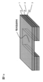
- FIG. 1 It is a fragmentary perspective view which shows an example of the laminated body of this invention. It is typical sectional drawing which shows a thermal radiation characteristic evaluation apparatus.
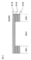
- A is sectional drawing which shows an example of the laminated body of this invention.
- B is sectional drawing which shows a mode that the laminated body of (a) was cut
- the laminate of the present invention is formed by laminating a radio wave transmitting member having radio wave permeability, a heat conducting member having electromagnetic wave shielding properties and / or a rigidity holding member having electromagnetic wave shielding properties in the thickness direction of the radio wave transmitting member.
- a radio wave transmitting member having radio wave permeability is simply referred to as a radio wave transmitting member
- a heat conducting member having electromagnetic wave shielding properties with respect to the thickness direction of the radio wave transmitting member is simply referred to as a heat conducting member
- the thickness direction of the radio wave transmitting member is
- a rigid holding member having electromagnetic wave shielding properties may be simply referred to as a rigid holding member.
- the laminate of the present invention has a radio wave transmitting member as an essential element and includes either a heat conducting member or a rigid retaining material, the obtained laminate exhibits electromagnetic wave shielding properties.
- the laminate of the present invention needs to have a radio wave transmission region composed only of a radio wave transmission member in a part of the laminate, and the radio wave transmission region needs to be a thin portion.
- the radio wave transmission region is composed of only a radio wave transmission member.
- an electromagnetic wave shielding function can be left in areas other than the radio wave transmission area.
- FIG. 1a is a partially transparent perspective view showing an embodiment of a laminate of the present invention, in which a radio wave transmitting member 1, a heat conducting member 2, and a rigid holding member 3 are laminated.
- a part of the laminated body has a radio wave transmission region constituted only by the radio wave transmission member 1 without both the heat conduction member 2 and the rigidity holding member 3.
- the region other than the radio wave transmitting region has a region where the radio wave transmitting member, the heat conducting member and the rigid holding member are laminated, and this region has the heat conducting member and the rigid holding member having electromagnetic wave shielding properties in the thickness direction. Therefore, it becomes an electromagnetic shielding region.
- the electromagnetic wave shielding region can be formed by disposing the electromagnetic wave shielding member in the thickness direction, and the electromagnetic wave shielding region can be formed by arranging the electromagnetic wave shielding member in the thickness direction. it can.
- the radio wave transmission region is a thin portion.
- the radio wave transmission region is a thin portion, as shown in FIGS. 1a and 1b, a region where only the radio wave transmission member 1 exists in the thickness direction of the laminate, and the radio wave transmission member 1 in that region. Is the thickness of the radio wave transmitting member 1 around the region or less.
- the thin-walled portion is usually an area that does not include at least one member among the members constituting the laminated body and is thinner than the area that includes all the members constituting the laminated body in the thickness direction.
- a region including all members constituting the laminate in the thickness direction may be referred to as an all member region.
- the thin portion in the radio wave transmission region has substantially the same thickness as the thickness of the radio wave transmission member 1 around the region.
- the radio wave transmission region By making the radio wave transmission region a thin part, for example, on the design surface side, which will be described later, it is possible to attach parts such as a nameplate (for example, with a logo) made of a material that does not impede radio wave transmission. Since components such as an antenna can be attached on the interior surface side opposite to the side, there is an effect of reducing the overall thickness including the laminate when these components are attached.
- the rigidity holding member 2 is arranged on the left and right sides so as to sandwich the radio wave transmission region provided at the approximate center of the radio wave transmission member 1, thereby forming a step on the surface of the laminate.
- the radio wave transmission region can be a thin portion relative to the region where the radio wave transmission member / rigidity holding member is laminated.
- the radio wave transmitting member 1 having the convex portion 1a and the laminated body in which the heat conducting member 2 and the rigid holding member 3 are laminated on both sides of the convex portion 1a are the laminated body of the present invention. Not treated as. Since this convex part area
- the region where the radio wave transmitting member 1 / heat conducting member 2 / rigidity holding member 3 positioned on both sides of the convex portion 1a of the radio wave transmitting member 1 is laminated with the heat conducting member 2 and the rigidity holding member 3 having electromagnetic wave shielding properties. Since it is included in the thickness direction, it becomes an electromagnetic wave shielding region. However, the thickness of the radio wave transmission member 1 in the electromagnetic wave transmission region is thicker than the thickness of the radio wave transmission member 1 in the vicinity of the region due to the presence of the convex portion 1a, and it is difficult to achieve weight reduction.
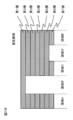
- a part of the laminate further includes a heat conduction region where the heat conduction member is exposed, and the heat conduction region is a thin portion.
- the thin-walled portion does not include at least one member among the members constituting the laminated body, and is thinner than the region (all member regions) including all the members constituting the laminated body in the thickness direction. It means being an area.
- the region constituted only by the radio wave transmitting member 1 is the radio wave transmitting region, and the region other than the radio wave transmitting region is the heat conducting member 2 and / or the rigidity holding member 3 having electromagnetic wave shielding properties. Therefore, it becomes an electromagnetic shielding region. Furthermore, in the electromagnetic wave shield region, by providing a region where the heat conducting member is exposed in the thickness direction, the configuration of radio wave transmitting member 1 / heat conducting member 2 / rigidity holding member 3 / low density member 4 / rigidity holding member 3 The heat conduction area
- both the heat conduction region and the radio wave transmission region include a region (all member regions) including all the members constituting the laminate in the thickness direction, for example, in FIG. 3, the radio wave transmission member 1 / heat conduction member 2 / rigidity holding member 3 /
- the effect of reducing the whole thickness at the time of attaching heat-emitting components, such as CPU, an antenna, etc. is acquired.
- the region including all the members constituting the laminated body in the thickness direction is a rigid holding member 3 / low density member 4 /
- the laminated structure of the rigid holding member 3 it can be set as the laminated body excellent in rigidity and lightness.
- radio wave transmission member the heat conduction member, the rigidity holding member, and the low density member.
- These members are functional members having a function, and when one material has two or more functions, they are handled as a plurality of functional members corresponding to one material.
- the radio wave transmitting member is made of a radio wave permeable material. Any material having radio wave permeability can be used without particular limitation.
- a thermosetting resin, a thermoplastic resin, or a ceramic material is preferably used as a material constituting the radio wave transmitting member.
- a nonconductive filler such as a nonconductive fiber to a thermosetting resin or a thermoplastic resin from the viewpoint of improving dimensional stability and reinforcing effect without impairing radio wave transmission.
- the radio wave transmitting member is preferably a fiber reinforced plastic containing at least one non-conductive fiber selected from organic fibers or ceramic fibers.
- a thermosetting resin or a thermoplastic resin is used as a resin
- a non-conductive fiber is selected from the viewpoint of radio wave transmission.
- organic fibers include aramid fibers, PBO fibers, polyphenylene sulfide fibers, polyester fibers, acrylic fibers, nylon fibers, polyethylene fibers, and the like.
- Ceramic fibers include glass fibers, silicon carbide fibers, silicon nitride fibers, and the like. Can be illustrated. Two or more of these fibers may be used in combination.
- the nonconductive fiber preferably contains at least glass fiber, and the mass content of the glass fiber contained in the nonconductive fiber is nonconductive. It is preferably 40 to 100% by mass, more preferably 50 to 100% by mass, and still more preferably 60 to 100% by mass with respect to the total mass of the fiber. Among these, it is particularly preferable that the non-conductive fiber is substantially a glass fiber because radio wave permeability is easily obtained.
- the “substantially glass fiber” referred to here includes 95% by mass or more of glass fiber in the non-conductive fiber even in consideration of impurities such as fiber that does not function as a reinforcing fiber. Means that.
- thermosetting resin examples include unsaturated polyester, vinyl ester resin, epoxy resin, phenol (resole type) resin, urea / melamine resin, thermosetting polyimide, and the like.
- examples include coalesced materials, modified products, and resins obtained by blending at least two of these. Among these, those containing an epoxy resin are preferable. Moreover, you may contain another filler and an additive according to a use etc. in a thermosetting resin.
- fillers and additives examples include elastomers or rubber components, inorganic fillers, flame retardants, conductivity imparting agents, antibacterial agents, insect repellents, deodorants, anti-coloring agents, mold release agents, antistatic agents, plastics Agents, colorants, pigments, dyes, foaming agents, antifoaming agents, coupling agents and the like.
- thermoplastic resin examples include polyethylene terephthalate (PET), polybutylene terephthalate (PBT), polytrimethylene terephthalate (PTT), polyethylene naphthalate (PEN), polyester such as liquid crystal polyester, polyethylene ( In addition to polyolefins such as PE), polypropylene (PP) and polybutylene, and styrenic resins, polyoxymethylene (POM), polyamide (PA), polycarbonate (PC), polymethylene methacrylate (PMMA), polyvinyl chloride (PVC) ), Polyphenylene sulfide (PPS), polyphenylene ether (PPE) (including modified PPE), thermoplastic polyimide (PI), polyamideimide (PAI), polyetherimide (PEI), Resulfone (PSU) (including modified PSU), polyethersulfone (PES), polyketone (PK), polyetherketone (PEK), polyetheretherketone (PEEK), poly
- thermoplastic elastomers examples thereof include thermoplastic elastomers, copolymers, modified products, and resins obtained by blending two or more types.
- An elastomer or a rubber component may be added to the thermoplastic resin in order to improve impact resistance.
- PPS is preferably used from the viewpoint of heat resistance and chemical resistance
- polycarbonate and styrene resin are used from the viewpoint of the appearance of the molded product and dimensional stability
- polyamide is preferably used from the viewpoint of the strength and impact resistance of the molded product.
- the thermoplastic resin may contain other fillers and additives depending on the application.
- fillers and additives examples include inorganic fillers, flame retardants, conductivity-imparting agents, crystal nucleating agents, ultraviolet absorbers, antioxidants, vibration damping agents, antibacterial agents, insect repellents, deodorants, and coloring prevention. Agents, heat stabilizers, mold release agents, antistatic agents, plasticizers, lubricants, colorants, pigments, dyes, foaming agents, antifoaming agents, coupling agents and the like.
- Combustion resistance is obtained by including a flame retardant in the resin used for the radio wave transmitting member 1, and, for example, it is preferable because safety can be ensured when ignited from an electric circuit inside the electronic device housing. From such a viewpoint, it is more preferable that both the thermosetting resin and the thermoplastic resin contain a flame retardant.
- a flame retardant to be used phosphorus imparting flame retardancy or a compound thereof is preferable.
- phosphorus-containing compounds such as phosphate esters, condensed phosphate esters, phosphaphenanthrene compounds and red phosphorus are used. Preferably used.
- red phosphorus is preferably used as a flame retardant because it has a high phosphorus atom content that serves to impart a flame retardant, and a small amount of flame retardant should be added to obtain a sufficient flame retardant effect.
- a flame retardant aid in addition to the flame retardant in order to improve the flame retardancy.
- flame retardant aids include metal hydroxides such as aluminum hydroxide, magnesium hydroxide, calcium hydroxide and tin hydroxide, inorganics such as calcium aluminate and zirconium oxide, and nitrogens such as melamine cyanurate.
- silicone type, phenol type and the like are preferably used.
- the heat conducting member is a member having a function of electromagnetic shielding and high thermal conductivity. From the viewpoint of increasing the thermal conductivity of the laminate, it is made of a material having high thermal conductivity.
- the material having a high thermal conductivity is not particularly limited, but for example, a ceramic material or a metal material is preferably used.
- a high thermal conductive resin whose thermal conductivity is increased by adding a high thermal conductive filler to the resin, which has been developed in recent years, can also be preferably used.
- the ceramic material include silica, zirconia, alumina, boron nitride, silicon carbide, silicon nitride, and carbon material.
- the metal material examples include elements selected from titanium, steel, aluminum, magnesium, iron, silver, gold, platinum, copper, and nickel, or alloys containing these elements as main components.
- a form of the metal material a film or sheet form can be used, but a thin film form formed by a thin film production method using a vacuum deposition method, a sputtering method, a vapor deposition method or the like can also be selected. Two or more of these materials can be used in combination.
- the thermal conductivity member preferably has a thermal conductivity of 10 W / m ⁇ K or more, more preferably in the range of 10 W / m ⁇ K to 3000 W / m ⁇ K, and more preferably 100 W / m ⁇ K to 3000 W. / M ⁇ K or less is more preferable, and a range of 200 W / m ⁇ K or more and 3000 W / m ⁇ K or less is most preferable.
- the heat conductivity of a heat conductive member can be measured by the laser flash method using the molded object comprised only from the member to measure.
- the rigid holding member is a member having an electromagnetic shielding property and a high rigidity function.
- the rigidity of the laminated body can be increased.
- a material with high rigidity for the rigidity holding member the rigidity of the laminate can be secured.
- a material having a high bending elastic modulus is used for the rigidity holding member.
- the member comprised from the material which has the highest bending elastic modulus in the material which has the electromagnetic wave shielding property used for a laminated body is defined as a rigidity holding member.
- an area including the rigidity holding member and an area having the highest rigidity in the plane of the laminate are defined as a rigidity holding area.
- the rigid holding member a material having a flexural modulus of 30 GPa or more is used for the rigid holding member.
- the bending elastic modulus of the rigid holding member is 50 GPa or more, more preferably 100 GPa or more.
- the bending elastic modulus of the rigid holding member can be measured according to ASTM D790, using a molded body composed only of the member to be measured, with the distance between the fulcrums being 32 times the thickness of the test piece.
- the flexural modulus of elasticity of the laminate is taken from the region to be measured so that the region thickness is the thickness of the test piece, and the test piece is used to The distance can be measured in accordance with ASTM D790, with the test piece thickness being 32 times the test piece thickness.
- the bending elastic modulus of the rigid holding member is higher than the bending elastic modulus of the radio wave transmitting member.
- the rigidity of the laminate can be further increased by increasing the bending elastic modulus of the rigidity holding member as compared with the bending elastic modulus of the radio wave transmitting member.
- the rigid holding member is made of a fiber reinforced plastic containing conductive fibers.
- the conductive fibers include metal fibers such as aluminum fibers, brass fibers, and stainless fibers, and polyacrylonitrile-based, rayon-based, lignin-based, and pitch-based carbon fibers (including graphite fibers). These conductive fibers may be used alone or in combination of two or more, and may be used in combination with fibers other than conductive fibers, such as insulating fibers.
- the resin used for the fiber reinforced plastic forming the rigid holding member either a thermosetting resin or a thermoplastic resin can be used, and the resin exemplified in the above-described radio wave transmitting member can be used. Furthermore, by adding a flame retardant to the resin used for the rigidity holding member, combustion resistance can be obtained. As the flame retardant used here, the flame retardant exemplified in the above-described radio wave transmitting member can be used.
- carbon fiber is contained in the conductive fiber used for the fiber reinforced plastic forming the rigid holding member.
- the conductive fibers listed above it is preferable to use carbon fibers that can efficiently increase the lightness and rigidity of the laminate.
- the conductive fibers in the rigid holding member are preferably continuous conductive fibers, and more preferably conductive fibers having an average fiber length of 10 mm or more.
- the continuous conductive fiber By using the continuous conductive fiber, the reinforcing effect of the conductive fiber can be efficiently expressed as compared with the discontinuous conductive fiber.
- the form of the conductive fiber layer a form in which cloths, filaments, blades, filament bundles, spun yarns, and the like are arranged in one direction can be suitably used. Also preferred is a method of reducing the anisotropy of the mechanical properties of the laminate by laminating the conductive fibers in one direction to form one layer and shifting the direction of the conductive fibers for each layer.
- the form of these layers may use one type independently, or may use two or more types together.
- a carbon fiber having good conductivity, high electromagnetic shielding properties, and a good balance of specific strength, specific rigidity, and light weight, particularly polyacrylonitrile-based carbon fiber because it can realize low cost. is there.
- the carbon fibers are continuous carbon fibers.
- the fiber reinforced plastic when the rigid holding member is formed of a fiber reinforced plastic containing carbon fiber, the fiber reinforced plastic preferably has a fiber mass content of carbon fiber in the range of 15% by mass to 80% by mass.
- the fiber mass content is less than 15% by mass, the electromagnetic shielding properties and rigidity are easily lost, and it becomes difficult to perform the intended function.
- the fiber mass content exceeds 80% by mass, a problem that voids are generated in the fiber-reinforced plastic tends to occur, and molding becomes difficult.
- the fiber mass content of the carbon fiber is preferably 25% by mass to 75% by mass, and more preferably 30% by mass to 70% by mass.
- the low density member is a member made of a material having a density of less than 1 g / cm 3 .
- the lightweight property of the laminate can be improved. From the viewpoint of further improving the light weight of the laminate, the smaller the density, the better.
- a thermoplastic resin, a thermosetting resin, etc. can be mentioned, Resin illustrated by the above-mentioned electromagnetic wave transmission member can be used.
- the material which expanded the fiber reinforced plastic which made these resin contain the reinforced fiber in the thickness direction can also be used preferably.
- the reinforcing fibers contained in such a material the reinforcing fibers listed in the rigidity holding member can be used.
- At least one radio wave transmitting member is arranged on the design surface side with respect to the heat conducting member and / or the rigid holding member. Furthermore, it is preferable to arrange at least one radio wave transmitting member on the outermost surface on the design surface side.
- a design surface means the surface provided in order to improve the designability of a product.
- the members constituting the laminate are laminated symmetrically in the thickness direction, and the heat conducting member is arranged at the center of the thickness.
- press forming can be performed by forming a symmetrical laminate having a configuration of radio wave transmission member 1 / rigidity holding member 3 / low density member 4 / rigidity holding member 3 / radiowave transmission member 1.
- the different thermal contraction difference which arises between each member can be eliminated, and curvature can be controlled.
- the layers are symmetrically laminated so as to have a configuration of radio wave transmitting member 1 / rigidity holding member 3 / heat conducting member 2 / rigidity holding member 3 / radio wave transmitting member 1, and heat conduction. It is more preferable that the member 2 is disposed at the thickness center portion.
- many of the heat conducting members 2 exhibiting high thermal conductivity are metal materials having high density. Therefore, the heat conducting member 2 has a central portion as shown in FIG. In addition, only one layer can be used, and the weight of the laminate can be reduced.
- the radio wave transmission region and the heat conduction region can be provided adjacent to each other or can be provided apart from each other.
- the radio wave transmission region composed of only the radio wave transmission member 1 in the thickness direction of the laminate and the heat conduction member 2 in the thickness direction of the laminate are partially exposed in the plane of the laminate.
- the radio wave transmission region and the heat conduction region are not continuous in the plane of the laminated body and can be arranged apart from each other.
- the layout of the radio wave transmission region and the heat conduction region can be freely selected according to the electronic component to be installed. For example, in the embodiment in which the electronic component is housed in the laminate of the present invention as shown in FIG.
- an antenna is installed in the radio wave transmission area composed only of the radio wave transmission member 1 in the thickness direction, and the thickness direction of the laminate is set.
- the radio wave transmitting member preferably has an electric field shielding property measured by the KEC method in a range of 0 dB or more and less than 20 dB in a frequency of 1 GHz band.
- the electric field shielding property of the laminate can be measured for each member constituting the laminate. Moreover, the electric field shielding property of each member can be measured using the molded object comprised only by each member. Specifically, the molding precursor formed by laminating a plurality of single materials is molded under the same molding process conditions as in the case of manufacturing the laminate, and the electric field shielding property is obtained using the molded body having the same equivalent thickness. taking measurement.
- the same equivalent thickness here is a target thickness of ⁇ 0.05 mm. If the thickness of the molded body is within this range, there is often no clear difference in the results of evaluation of electromagnetic wave shielding properties.
- electric field shielding is used as a measure of electromagnetic shielding properties. A schematic diagram of an electric field shielding measuring apparatus is shown in FIG.
- the electric field shielding property measured by the KEC method is in the range of 0 dB or more and less than 20 dB in the frequency band of 1 GHz, sufficient radio wave permeability can be ensured in the radio wave transmission region. More preferably, it is the range of 0 dB or more and 10 dB or less, and further preferably the range of 0 dB or more and 5 dB or less.
- the rigid holding member and the heat conducting member preferably have an electric field shielding property measured by the KEC method in the range of 20 dB to 80 dB in the frequency 1 GHz band.
- the rigid holding member and the heat conducting member by making the electric field shielding property measured by the KEC method in the range of 20 dB to 80 dB in the frequency 1 GHz band, sufficient electromagnetic wave shielding property can be secured in the electromagnetic wave shielding region. . More preferably, it is the range of 30 dB or more and 80 dB or less, More preferably, it is the range of 50 dB or more and 80 dB or less.
- the above-described laminate can be used as it is, for example, in an electronic device casing, but the molded laminate is integrated with another member having a detailed shape such as a boss or a rib to be used as an integrated molded product. As a function can be enhanced.
- another member is manufactured in advance and bonded to the laminate, or the laminate is inserted into an injection mold and clamped, and a part of the laminate is By covering and integrating a thermoplastic resin as another member so as to cover it, it is possible to obtain an integrated molded product to which another part is provided.
- a method for producing a laminate suitable for obtaining the laminate of the present invention will be described with reference to the drawings.
- a preliminary laminate is produced in which a radio wave transmitting member / rigidity holding member / heat conducting member / rigidity holding member / radiowave transmission member are laminated symmetrically in the thickness direction.
- each member is plate-shaped, and as a method for fixing each layer, a pre-laminated body in which each layer is in close contact can be obtained by using a method of applying an adhesive or a press molding method.
- a part of the preliminary laminated body is cut and removed to remove the rigidity holding member / heat conduction member / rigidity holding member / radio wave transmission member, so that the thickness direction of the laminated body It is possible to provide a radio wave transmission region in which only the radio wave transmission member 1 remains on the substrate, and similarly, by cutting and removing a part of the rigid holding member / radio wave transmission member of the preliminary laminate, A heat conduction region in which the heat conduction member 2 is exposed in the direction can be provided.
- a preliminary laminate is produced in which a plate-like radio wave transmission member, a plate-like heat conduction member, and / or a plate-like rigidity holding member are laminated in the thickness direction.
- the radio wave transmission region is formed by cutting and removing members other than the radio wave transmission member in a predetermined region in the surface of the preliminary laminated body.
- a pre-lamination body in which a plate-like radio wave transmission member and a plate-like heat conduction member are laminated in the thickness direction is prepared, Cutting and removing members other than the radio wave transmitting member in a predetermined area in to form a radio wave transmitting area, and cutting other members in another predetermined area in the preliminary laminated body until the heat conducting member is exposed, It is removed to form a heat conduction region.
- a laminate having the radio wave transmission region and the heat conduction region can be obtained.
- a part of the plate-like rigid holding member is cut and removed by using a cutting machine such as an NC machine, and a portion to be a heat conduction region is cut out.
- the rigid holding member 3 having the above is manufactured.
- the heat conducting member 2 is formed in the cutout region of the rigid holding member 3 by forming a pre-laminated body in which the plate-like rigid holding member 3 / the heat conducting member 2 / the rigid holding member 3 having a notch are laminated in this order.
- An exposed heat conducting region can be provided.
- the radio wave transmitting member 1 is laminated on the plate-like rigid holding member 3 side, and the radio wave transmitting member 1 / rigid holding member 3 / heat
- a region in which the notch is provided in a region different from the heat conduction region of the laminated body becomes a radio wave transmission region.
- the method of sticking each layer of a laminated body the method of apply
- the portion for forming the heat conduction region and the radio wave transmission region may be a through hole instead of the notch.
- a cutout or a through hole is provided in a preliminary laminated body including a plate-like heat conducting member and / or a plate-like rigid holding member, and the preliminary laminated body is formed into a plate.
- a radio wave transmission region is formed by laminating the radio wave transmission members.
- a cutout or a through hole is provided in a preliminary laminate including a plate-like member other than the heat conduction member, and the preliminary laminate is provided with a plate-like member.
- a heat conduction region is formed by laminating the heat conduction member, and a cutout or a through-hole is provided in a region other than the heat conduction region in the pre-lamination body in which the heat conduction region is formed.
- a radio wave transmission region is formed by laminating the radio wave transmission member.
- any one of the radio wave transmitting member, the rigidity holding member, and the heat conducting member is a resin-containing member
- a press molding method is used for the integration of the layers of the laminate, and the radio wave transmission is performed before press molding.
- a radio wave transmission region or a heat conduction region can be provided by laminating a member cut into a predetermined shape in consideration of a region to be a region or a heat conduction region and press-molding the member.
- a radio wave transmission region composed only of a radio wave transmission member can be provided in the thickness direction of the laminate by disposing a member having an electromagnetic shielding property only in a region avoiding the radio wave transmission region. .
- the laminate having the heat conduction region where the heat conduction member is exposed is provided.
- a member provided with a notch or a through hole may be arranged in a portion to be the radio wave transmission region or the heat conduction region.
- the divided members may be combined and arranged in addition to the portion to be the radio wave transmission region or the heat conduction region.
- a test piece is cut out from a molded body composed of a material to be measured, or a rigid holding region or a whole member region of a laminate to be measured into a length of 50 mm, a width of 25 mm, and (each thickness), and a distance between fulcrums is tested.
- the flexural modulus was determined according to ASTM D790 as 32 times the piece thickness.
- the bending elastic modulus of the obtained laminate was evaluated according to the following criteria.
- AA, A, and B are acceptable, and C and D are unacceptable.
- AA 100 GPa or more A: 50 GPa or more and less than 100 GPa B: 30 GPa or more and less than 50 GPa C: 5 GPa or more and less than 30 GPa D: Less than 5 GPa
- the density was determined by using an underwater substitution method for a molded body composed of a material to be measured, or a rigid holding region or a whole member region of a laminate to be measured. About the rigidity maintenance area
- AA Less than 1.2 g / cm 3 A: 1.2 g / cm 3 or more and less than 1.7 g / cm 3 B: 1.7 g / cm 3 or more and less than 2.3 g / cm 3 C: 2.3 g / cm 3 or more Less than 2.5 g / cm 3 D: 2.5 g / cm 3 or more
- FIG. 8 is a schematic longitudinal sectional view of the electric field shielding measuring apparatus.
- the electric field shielding measuring device 6 includes a measuring casing made of a metal tube 10. The internal space of the metal tube 10 is shielded from the outside. A signal transmitting antenna 7 and a signal receiving antenna 9 are provided in the internal space of the metal tube 10. In the metal tube 10, the measurement sample 5 can be inserted between both antennas from the outside. The measurement sample 5 has a measurement sample thickness 8.
- the measurement sample 5 is inserted between the signal transmitting antenna 7 and the signal receiving antenna 9 in the space shielded by the metal tube 10, and the electric field strength due to the presence or absence of the sample is measured.
- the measuring device 6 measures the electric field strength depending on the presence or absence of the measurement sample 5.
- the field strength of the space to be measured when the measurement sample is not a E 0 [V / m]
- the electric field shielding properties Obtained by the following formula.
- the sign of the measured value is the direction in which the positive direction has a shielding effect.
- Field shielding (shield effect) 20log 10 E 0 / E X [dB]
- the radio wave transmission was judged from the measurement result of the electric field shielding property measured in the radio wave transmission region.
- A is a case having an electric field shielding property of 0 dB or more and less than 10 dB
- B is a case having an electric field shielding property of 10 dB or more and less than 20 dB, and judgments A and B are acceptable.
- the case where it had electric field shielding property of 20 dB or more was set as C, and it was set as the failure.
- ⁇ when there was no radio wave transmission region in the laminate, it was not evaluated ( ⁇ ).
- the electromagnetic shielding property was judged from the measurement result of the electric field shielding property measured for the electromagnetic shielding region.
- A was given when the electric field shielding property was 50 dB or more
- B was given when the electric field shielding property was 20 dB or more and less than 50 dB
- the judgments A and B were passed.
- the case where it had electric field shielding property of less than 20 dB was set as C, and it was set as the failure.
- a molded body composed of a material to be measured is a disk-shaped sample having a diameter of 10 mm and a thickness of 3 to 6 mm, and the molded body is measured using a laser flash method thermal constant measuring device TC-3000 manufactured by Vacuum Riko Co., Ltd. Specific heat and thermal diffusivity were measured, and the thermal conductivity of the material was calculated by the following formula.
- K Cp ⁇ ⁇ ⁇ ⁇ ⁇
- K is the thermal conductivity of the molded body
- Cp is the specific heat of the molded body
- ⁇ is the thermal diffusivity of the molded body
- ⁇ is the density of the molded body.
- the thickness of the molded body was changed according to the thermal conductivity of the molded body. The sample having a large thermal conductivity was thick and the small sample was thin. Specifically, after laser irradiation, the temperature on the back surface of the sample rises, and it takes several tens of milliseconds to reach the maximum temperature. The time t until the temperature rises by 1/2 of the temperature rise width ⁇ Tm at that time t. The thickness of the sample was adjusted so that 1/2 was 10 msec or more (maximum 15 msec).
- Specific heat was determined by sticking glassy carbon as a light receiving plate on the front of the sample and measuring the temperature rise after laser irradiation with an R thermocouple bonded to the center of the back of the sample. The measured values were calibrated using sapphire as a standard sample. The thermal diffusivity was obtained by coating with carbon spray until both surfaces of the sample were invisible, and measuring the temperature change on the back of the sample after laser irradiation with an infrared detector. In addition, when thermal conductivity showed anisotropy, the maximum value of the measured value was made into the representative value.
- a test piece was cut out to a size of 120 ⁇ 150 mm from the heat conduction region of the laminate.
- the heat generating member was fixed to the heat conducting member side at the center of the cut out test piece with an adhesive.
- a test piece 11 having a heat generating member 12 bonded thereon was placed on a heat dissipation characteristic evaluation apparatus formed of a heat insulating plate 14 and an aluminum tape 13.
- the heat generating member has a cylindrical shape with a diameter of 15 mm.
- the heating member was energized with 8 W of power for 5 minutes, the temperature of the heating member after 10 minutes, and the back surface of the test piece on which the heating member was disposed (outside air side) )
- the thermocouple 15b and the thermocouple 15a Were measured by the thermocouple 15b and the thermocouple 15a, and the difference between the measured values was used as a criterion for determining the heat dissipation characteristics.
- the measurement position on the back surface (outside air side) of the test piece was measured at a location 50 mm away from the center of the test piece in the longitudinal direction of the test piece.
- the evaluation result of the heat dissipation characteristics is that the difference between the two measured temperatures is less than 20 ° C. and A is 20 ° C. or more and less than 40 ° C., and judgments A and B are acceptable. The case of 40 degreeC or more was made disqualified as C determination. In addition, when there was no heat conduction region in the laminated body, it was not evaluated ( ⁇ ). When the laminate contains an anisotropic material, measurement is performed for each region in the 0 ° direction and the 90 ° direction rotated in the vertical direction, and the average value of each measurement temperature difference is used as a criterion. It was.
- This dry blend product was put in from a hopper of a twin screw extruder, melt kneaded in the extruder, and then extruded from a 400 mm wide T-die. Then, it cooled and solidified by taking up with a 60 degreeC chill roll, and obtained the polypropylene sheet (material 4) of thickness 0.3mm.
- Example 1 Three glass fiber reinforced sheets of material 1 were laminated to obtain a molding. About the obtained molding object, it hot-press-molded, and after 30 minutes passed from pressurization, the board surface was opened, the tool board was taken out from the press molding machine, and the glass fiber reinforced plastic which the epoxy resin hardened was obtained. In hot press molding, the object to be molded is sandwiched between release films, further sandwiched between tool plates, placed between the panel surfaces of a press molding machine with a panel surface temperature of 150 ° C., and then the panel surface is closed to a pressure of 1.5 MPa. Was pressurized.
- the aluminum sheet of the material 2 is cut into a predetermined dimension, and as shown in FIG. 11A, the epoxy adhesive is applied only to the positions of the regions A and C of the glass fiber reinforced plastic as the first layer.
- the aluminum sheet of the predetermined dimension which is a 2nd layer was bonded together, and the laminated body was obtained.
- the surface of the glass fiber reinforced plastic opposite to the surface on which the aluminum sheet was bonded was used as the design surface.
- the glass fiber reinforced plastic corresponds to a radio wave transmitting member
- the aluminum sheet corresponds to a heat conducting member.
- the obtained laminate had a good appearance with no joining line appearing on the design surface side.
- the obtained laminated body was cut and divided
- the evaluation results are shown in Table 2.
- the laminate had a radio wave transmission region, a heat conduction region, and an electromagnetic wave shield region in the plane, and both the region A and the region C had a good bending elastic modulus and also exhibited a function as a rigidity holding region.
- Example 2 Three carbon fiber reinforced sheets of material 3 were laminated in the order of 0 ° / 90 ° / 0 ° in the fiber direction to obtain a molding.
- the obtained object to be molded was hot press-molded in the same manner as in Example 1, and after 30 minutes from pressurization, the board surface was opened, the tool plate was taken out from the press molding machine, and the carbon fiber in which the epoxy resin was cured A reinforced plastic was obtained.
- Example 11A a laminate having the structure shown in FIG. 11A was obtained in the same manner as in Example 1 except that the carbon fiber reinforced plastic obtained as described above was used instead of the aluminum sheet.
- the glass fiber reinforced plastic corresponds to a radio wave transmitting member, and the carbon fiber reinforced plastic corresponds to a rigid holding member.
- the obtained laminate had a good appearance with no joining line appearing on the design surface side.
- the obtained laminated body was cut and divided into regions A, B, and C as shown in FIG. 11B, and the characteristics were evaluated for each region. .
- the evaluation results are shown in Table 2.
- the laminate does not have a heat conduction region in the plane, it has a radio wave transmission region and an electromagnetic wave shielding region, and both the region A and the region C have a good bending elastic modulus and also function as a rigidity holding region. Demonstrated.
- Example 3 The aluminum sheet of material 2 was cut to a predetermined size, and the carbon fiber reinforced plastic obtained in Example 2 was cut to a predetermined size.
- the carbon fiber reinforced plastic having a predetermined size as the second layer is provided only at the positions of the regions A and C of the glass fiber reinforced plastic obtained in Example 1 as the first layer.
- the aluminum sheet of the predetermined dimension which is a 3rd layer was each arrange
- the glass fiber reinforced plastic corresponds to a radio wave transmitting member
- the carbon fiber reinforced plastic corresponds to a rigid holding member
- the aluminum sheet corresponds to a heat conducting member.
- the obtained laminate had a good appearance with no joining line appearing on the design surface side. Moreover, the obtained laminated body was cut and divided into an area A, an area B, and an area C shown in FIG. 12 using an auto cutter processing machine, and the characteristics of each area were evaluated. The evaluation results are shown in Table 2.
- the laminate had a radio wave transmission region, a heat conduction region, and an electromagnetic wave shield region in the plane, and both the region A and the region C had a good flexural modulus, and exhibited a function as a rigidity holding region.
- Example 4 The aluminum sheet of material 2 was cut to a predetermined size, and the carbon fiber reinforced plastic obtained in Example 2 was cut to a predetermined size.
- the aluminum sheet having a predetermined size as the second layer is provided only at the positions of the regions A and C to E of the glass fiber reinforced plastic obtained in Example 1 as the first layer.
- the carbon fiber reinforced plastic having a predetermined dimension as the third layer was further disposed only in the positions of the regions A, C and E, and the layers were bonded together with an epoxy resin adhesive to obtain a laminate.
- the glass fiber reinforced plastic corresponds to a radio wave transmitting member
- the carbon fiber reinforced plastic corresponds to a rigid holding member
- the aluminum sheet corresponds to a heat conducting member.
- the obtained laminate had a good appearance with no joining line appearing on the design surface side. Further, using an auto cutter processing machine, the obtained laminate was cut and divided into region A, region B, region C, region D, and region E shown in FIG. 13, and the characteristics were evaluated for each region. It was. The evaluation results are shown in Table 2.
- the laminated body has a radio wave transmission region, a heat conduction region, and an electromagnetic wave shielding region in the plane, and each of the region A, the region C, and the region E has a good bending elastic modulus and functions as a rigidity holding region. Expressed.
- Example 5 Using three glass fiber reinforced sheets of material 1 and two aluminum sheets of material 2, an aluminum sheet / glass fiber reinforced sheet / glass fiber reinforced sheet / glass fiber reinforced sheet / aluminum sheet are laminated in this order. Obtained. About the obtained molded object, it heat-press-molded like Example 1, and after 30 minutes passed from pressurization, a board surface is opened, it takes out with a tool board from a press molding machine, and the epoxy of a glass fiber reinforcement sheet
- seat was cut using NC processing machine, and the laminated body which only left the glass fiber reinforced plastic layer in the center part of the thickness direction in the area
- arranged to the 1st layer and 3rd layer in FIG. 14 corresponds to a heat conductive member
- arranged to the 2nd layer corresponds to a radio wave transmission member.
- the obtained laminate had a good appearance even when a recess was provided on the design surface side. Moreover, the obtained laminated body was cut and divided into an area A, an area B, and an area C shown in FIG. 14 using an auto cutter machine, and the characteristics were evaluated for each area. The evaluation results are shown in Table 2.
- the laminate had a radio wave transmission region, a heat conduction region, and an electromagnetic wave shield region in the plane, and the regions A and C also had a good bending elastic modulus, and exhibited a function as a rigidity holding region.
- Example 6 Using two aluminum sheets of material 2 and one polypropylene sheet of material 4, an aluminum sheet / polypropylene sheet / aluminum sheet was laminated in this order to obtain a molding.
- the tool board with which the molding object was pinched was quickly conveyed to a cooling press machine.
- the board surface was opened and the tool plate was taken out from the cooling press machine to obtain a pre-laminated body in which the respective layers were sufficiently adhered.
- the aluminum in the portion located in the region B of the resulting laminate on both the design surface side of the preliminary laminate and the interior surface side opposite to the design surface side was obtained.
- arranged to the 1st layer and 3rd layer in FIG. 14 corresponds to a heat conductive member
- arranged to the 2nd layer corresponds to a low density member.
- the obtained laminate had a good appearance even when a recess was provided on the design surface side. Moreover, the obtained laminated body was cut and divided into an area A, an area B, and an area C shown in FIG. 14 using an auto cutter machine, and the characteristics were evaluated for each area. The evaluation results are shown in Table 2.
- the laminate has a radio wave transmission area, a heat conduction area, and an electromagnetic wave shield area in the plane, and the areas A and C are excellent in light weight, have sufficient bending elastic modulus, and exhibit a function as a rigidity holding area. did.
- Example 7 Using 4 glass fiber reinforced sheets of material 1, 4 carbon fiber reinforced sheets of material 3 and 1 polypropylene sheet of material 4, glass fiber reinforced sheet / glass fiber reinforced sheet / carbon fiber reinforced sheet (0 °) / Carbon fiber reinforced sheet (90 °) / polypropylene sheet / carbon fiber reinforced sheet (90 °) / carbon fiber reinforced sheet (0 °) / glass fiber reinforced sheet / glass fiber reinforced sheet were laminated in this order to obtain a molding. . About the obtained molded object, after performing hot press molding and cooling press molding similarly to Example 6, the board surface is opened, and the whole tool plate is taken out from the cooling press machine, and a glass fiber reinforced sheet and a carbon fiber reinforced sheet are obtained.
- a pre-laminated body comprising glass fiber reinforced plastic / carbon fiber reinforced plastic / polypropylene sheet / carbon fiber reinforced plastic / glass fiber reinforced plastic as first to fifth layers, in which the epoxy resin is cured and the respective layers are sufficiently adhered to each other. Obtained.
- the carbon fiber reinforced plastic / polypropylene sheet in a portion located in the region B of the resulting laminate on the interior surface side opposite to the design surface side of the preliminary laminate / Carbon fiber reinforced plastic / Glass fiber reinforced plastic is cut using an NC processing machine to obtain a laminate that leaves only glass fiber reinforced plastic placed on the design surface in the thickness direction of region B as shown in FIG. It was.
- the glass fiber reinforced plastics disposed in the first layer and the fifth layer in FIG. 15 correspond to radio wave transmitting members
- the carbon fiber reinforced plastics disposed in the second layer and the fourth layer are rigid holding members having electromagnetic wave shielding properties.
- the polypropylene sheet arranged in the third layer corresponds to a low density member.
- the obtained laminate had a good appearance with no joining line appearing on the design surface side. Moreover, the obtained laminated body was cut and divided into an area A, an area B, and an area C shown in FIG. 15 using an auto cutter machine, and the characteristics were evaluated for each area. The evaluation results are shown in Table 3. Although the laminate has no heat conduction region in the plane, it has a radio wave transmission region and an electromagnetic wave shielding region, and the regions A and C have good bending elastic modulus and light weight, and function as a rigidity holding region. Expressed.
- Example 8 Using 4 glass fiber reinforced sheets of material 1, 1 aluminum sheet of material 2 and 4 carbon fiber reinforced sheets of material 3, glass fiber reinforced sheet / glass fiber reinforced sheet / carbon fiber reinforced sheet (0 °) / Carbon fiber reinforced sheet (90 °) / aluminum sheet / carbon fiber reinforced sheet (90 °) / carbon fiber reinforced sheet (0 °) / glass fiber reinforced sheet / glass fiber reinforced sheet were laminated in this order to obtain a molding. .
- Example 2 About the obtained molding object, it heat-press-molds similarly to Example 1, and after 30 minutes have passed since pressurization, a board surface is opened, it takes out with a tool board from a press molding machine, a glass fiber reinforcement sheet
- a pre-laminated body comprising glass fiber reinforced plastic / carbon fiber reinforced plastic / aluminum sheet / carbon fiber reinforced plastic / glass fiber reinforced plastic as first to fifth layers, in which the epoxy resin of the sheet is cured and the respective layers are sufficiently adhered to each other Got.
- the carbon fiber reinforced plastic / aluminum sheet / carbon fiber reinforced part of the laminated body obtained on the interior surface side opposite to the design surface side The plastic / glass fiber reinforced plastic is cut using an NC processing machine, leaving only the glass fiber reinforced plastic placed on the design surface in the thickness direction of the region B, and further, located on the interior surface side in the region D of the resulting laminate.
- the carbon fiber reinforced plastic / glass fiber reinforced plastic was cut using an NC processing machine, and an aluminum sheet was exposed on the interior surface side in the thickness direction of the region D to obtain a laminate as shown in FIG. .
- the glass fiber reinforced plastics arranged in the first layer and the fifth layer in FIG. 16 correspond to the radio wave transmitting member
- the aluminum sheet arranged in the third layer corresponds to the heat conducting member
- the second layer and the fourth layer The carbon fiber reinforced plastic disposed in the section corresponds to a rigid holding member.
- the obtained laminate had a good appearance with no joining line appearing on the design surface side.
- the obtained laminate was cut and divided into regions A, B, C, D, and E shown in FIG. It was.
- the evaluation results are shown in Table 3.
- the laminate had a radio wave transmission region, an electromagnetic wave shield region, and a heat conduction region in the plane, and the regions A, C, and E had a good bending elastic modulus and exhibited a function as a rigidity holding region.
- Example 9 One glass fiber reinforced plastic obtained in Example 1, one aluminum sheet of material 2, four carbon fiber reinforced sheets of material 3, and one polypropylene sheet of material 4 were used.
- a notch penetrating in the thickness direction of the sandwich structure was provided at the position of region D of the obtained laminate using an NC processing machine. Furthermore, after pasting the sandwich structure provided with this notch with an aluminum sheet using an epoxy adhesive, a notch penetrating in the thickness direction is provided at the position of region B of the laminate obtained in the same manner.
- a preform was obtained. By bonding the glass fiber reinforced plastic obtained in Example 1 to the aluminum sheet side of the obtained preform (sandwich structure / aluminum sheet) using an epoxy adhesive, as shown in FIG.
- region B a radio wave transmission region in which only the glass fiber reinforced plastic layer disposed on the design surface remained was provided
- the region D a laminate provided with a heat conduction region in which the aluminum sheet was exposed on the interior surface side was obtained.
- the glass fiber reinforced plastic disposed in the first layer in FIG. 17 corresponds to a radio wave transmitting member
- the aluminum sheet disposed in the second layer corresponds to a heat conducting member
- Plastic corresponds to the rigid holding member
- the polypropylene sheet disposed in the fourth layer corresponds to the low density member.
- region B is a radio wave transmission region with a thin portion
- region D is a heat conduction region with a thin portion.
- the obtained laminate had a good appearance with no joining line appearing on the design surface side. Further, using an auto cutter processing machine, the obtained laminate was cut and divided into regions A, B, C, D, and E shown in FIG. It was. The evaluation results are shown in Table 3.
- the laminate has a radio wave transmission region, an electromagnetic wave shield region, and a heat conduction region in the plane, and regions A, C, and E have good bending elastic modulus and light weight, and function as a rigidity holding region. Expressed.
- Example 10 Glass fiber reinforced sheet / glass fiber reinforced sheet / aluminum using 4 glass fiber reinforced sheets of material 1, 2 aluminum sheets of material 2, 4 carbon fiber reinforced sheets of material 3 and 1 polypropylene sheet of material 4 Sheet / carbon fiber reinforced sheet (0 °) / carbon fiber reinforced sheet (90 °) / polypropylene sheet / carbon fiber reinforced sheet (90 °) / carbon fiber reinforced sheet (0 °) / aluminum sheet / glass fiber reinforced sheet / glass A molded article was obtained by laminating fiber reinforced sheets in this order. About the obtained molded object, after performing hot press molding and cooling press molding similarly to Example 6, the board surface is opened, and the whole tool plate is taken out from the cooling press machine, and a glass fiber reinforced sheet and a carbon fiber reinforced sheet are obtained. First to seventh layers of glass fiber reinforced plastic / aluminum sheet / carbon fiber reinforced plastic / polypropylene sheet / carbon fiber reinforced plastic / aluminum sheet / glass fiber reinforced plastic, with the epoxy resin cured and sufficient adhesion between each layer A preliminary laminate was obtained.
- the aluminum sheet / carbon fiber reinforced plastic / polypropylene sheet / part of the laminated body obtained on the interior surface side opposite to the design surface side The carbon fiber reinforced plastic / aluminum sheet / glass fiber reinforced plastic is cut using an NC processing machine, leaving only the glass fiber reinforced plastic placed on the design surface in the thickness direction of the region B, and the laminate obtained on the interior surface side.
- a portion of the glass fiber reinforced plastic located in the region D of the body is cut using an NC processing machine, and a sixth layer of aluminum sheet is exposed on the interior surface side in the thickness direction of the region D, as shown in FIG. Got the body. Note that the glass fiber reinforced plastics disposed in the first layer and the seventh layer in FIG.
- the aluminum sheets disposed in the second layer and the sixth layer correspond to heat conducting members having electromagnetic wave shielding properties.
- the carbon fiber reinforced plastic disposed in the third layer and the fifth layer corresponds to a rigid holding member having electromagnetic wave shielding properties, and the polypropylene sheet disposed in the fourth layer corresponds to a low density member.
- the obtained laminate had a good appearance with no joining line appearing on the design surface side. Further, using an auto cutter processing machine, the obtained laminate was cut and divided into areas A, B, C, D, and E shown in FIG. 18, and the characteristics of each area were evaluated. It was. The evaluation results are shown in Table 3.
- the laminate had a radio wave transmission region, an electromagnetic wave shield region, and a heat conduction region in the plane, and had a good bending elastic modulus in the rigid holding region.
- Example 11 Using the preliminary laminate obtained in Example 10, the aluminum sheet / carbon fiber reinforced plastic / polypropylene sheet of the portion located in the region B of the laminate obtained on the interior surface side opposite to the design surface side / Carbon fiber reinforced plastic / Aluminum sheet / Glass fiber reinforced plastic was cut with an NC processing machine, leaving only the glass fiber reinforced plastic placed on the design surface side in the thickness direction of region B, and on the interior surface side, The portion of the resulting laminate that is located in region D is cut with carbon fiber reinforced plastic / polypropylene sheet / carbon fiber reinforced plastic / aluminum sheet / glass fiber reinforced plastic using an NC processing machine, and the interior surface in the thickness direction of region D As shown in FIG. 19, the second layer of aluminum sheet is exposed on the side. To obtain a laminate.
- the obtained laminate had a good appearance with no joining line appearing on the design surface side.
- the obtained laminate was cut and divided into regions A, B, C, D, and E shown in FIG. It was.
- the evaluation results are shown in Table 3.
- the laminate had a radio wave transmission region, an electromagnetic wave shield region, and a heat conduction region in the plane, and the regions A, C, and E had a good bending elastic modulus and exhibited a function as a rigidity holding region.
- the laminate obtained in this example has a thin thickness in the heat conduction region, so that the overall thickness when a heat-generating component such as a CPU is attached is reduced. be able to.
- Example 1 The glass fiber reinforced plastic obtained in Example 1 was used as a radio wave transmitting member to form a laminate composed of only the first layer shown in FIG.
- the obtained laminate had a good appearance with no joining line appearing on the design surface side.
- Table 4 shows the results of evaluating the characteristics of the obtained laminate. Although this laminate had a radio wave transmission region, it was greatly inferior in electromagnetic shielding properties. Also, the flexural modulus of the laminate was inferior.
- the obtained laminate had a good appearance with no joining line appearing on the design surface side.
- Table 4 shows the results of evaluating the characteristics of the obtained laminate.
- the laminate had an electromagnetic wave shielding region and a heat conduction region, but did not have a radio wave transmission region. Moreover, although the bending elastic modulus of the laminate was good, it was inferior in lightness.
- Example 3 The carbon fiber reinforced plastic obtained in Example 2 was used as a rigid holding member having electromagnetic wave shielding properties to form a laminate composed of only the first layer shown in FIG.
- the obtained laminate had a good appearance with no joining line appearing on the design surface side.
- Table 4 shows the results of evaluating the characteristics of the obtained laminate.
- the obtained laminate had an electromagnetic wave shielding region, but did not have a radio wave transmission region and a heat conduction region. Moreover, both the bending elastic modulus and lightness of the laminate were good.
- the obtained laminate had a good appearance with no joining line appearing on the design surface side.
- Table 4 shows the results of evaluating the characteristics of the obtained laminate. Although the obtained laminate had a radio wave transmission region, it was greatly inferior in electromagnetic wave shielding properties. Moreover, although the lightweight property of a laminated body is excellent, it was greatly inferior to the bending elastic modulus.
- Example 5 A laminated body shown in FIG. 11A was obtained in the same manner as in Example 1 except that the glass fiber reinforced plastic as the first layer was changed to the carbon fiber reinforced plastic obtained in Example 2.
- the carbon fiber reinforced plastic corresponds to a rigid holding member having electromagnetic wave shielding properties
- the aluminum sheet corresponds to a heat conducting member having electromagnetic wave shielding properties.
- the obtained laminate had a good appearance with no joining line appearing on the design surface side.
- the obtained laminated body was cut and divided
- the evaluation results are shown in Table 4.
- the laminate had no radio wave transmission region in the plane, it had a heat conduction region and an electromagnetic wave shielding region, and region A and region C also had an excellent flexural modulus and exhibited a function as a rigidity holding region.
- region B of the obtained laminated body is cut on the design surface side using the obtained preliminary laminated body, and aluminum sheet / carbon fiber reinforced in the thickness direction of the area B
- the laminated body shown in FIG. 21 leaving only the sheet was obtained.
- the carbon fiber reinforced plastic disposed in the first layer and the third layer in FIG. 21 corresponds to a rigid holding member having electromagnetic wave shielding properties
- the aluminum sheet disposed in the second layer is a heat conducting member having electromagnetic wave shielding properties. Applicable.
- the obtained laminate had a good appearance even when a recess was provided on the design surface side. Moreover, the obtained laminated body was cut and divided into an area A, an area B, and an area C shown in FIG. 21 using an auto cutter processing machine, and the characteristics of each area were evaluated. The evaluation results are shown in Table 4. Although the obtained laminate had no radio wave transmission region in the plane, it had a heat conduction region and an electromagnetic wave shielding region, and regions A and C also had an excellent flexural modulus and exhibited a function as a rigidity holding region. .
- the obtained laminate had a good appearance with no joining line appearing on the design surface side.
- Table 4 shows the results of evaluating the characteristics of the obtained laminate. Although the obtained laminate had a radio wave transmission region, it was greatly inferior in electromagnetic wave shielding properties. Moreover, although the lightweight property of the laminated body was excellent, it was inferior to the bending elastic modulus.
- the obtained laminate had a good appearance with no joining line appearing on the design surface side.
- Table 4 shows the results of evaluating the characteristics of the obtained laminate.
- the obtained laminate had an electromagnetic wave shielding region, but did not have a radio wave transmission region and a heat conduction region. Moreover, the bending elastic modulus and lightness of the laminate were excellent.
- Example 9 The preliminary laminate obtained in Example 8 was used as it was to obtain a laminate as shown in FIG. Note that the glass fiber reinforced plastic disposed in the first layer and the fifth layer in FIG. 23 corresponds to a radio wave transmitting member, and the carbon fiber reinforced plastic disposed in the second layer and the fourth layer is a rigid holding member having electromagnetic wave shielding properties.
- the aluminum sheet disposed in the third layer corresponds to a heat conducting member having electromagnetic wave shielding properties.
- the obtained laminate had a good appearance with no joining line appearing on the design surface side.
- Table 4 shows the results of evaluating the characteristics of the obtained laminate.
- the obtained laminate had an electromagnetic wave shielding region, but did not have a radio wave transmission region and a heat conduction region.
- the laminate and the integrated molded body of the present invention can be suitably used for automobile interior and exterior, electrical / electronic equipment casings, bicycles, sporting goods structural materials, aircraft interior materials, transportation boxes, and the like.
Abstract
Description
測定すべき材料から構成された成形体、または測定すべき積層体の剛性保持領域もしくは全部材領域から、長さ50mm、幅25mm、(各厚み)に、試験片を切り出し、支点間距離を試験片厚みの32倍として、ASTM D790に準拠して曲げ弾性率を求めた。さらに、得られた積層体の曲げ弾性率を以下の基準で評価した。AA、A、Bが合格であり、C、Dが不合格である。
AA:100GPa以上
A:50GPa以上100GPa未満
B:30GPa以上50GPa未満
C:5GPa以上30GPa未満
D:5GPa未満
測定すべき材料から構成された成形体、または測定すべき積層体の剛性保持領域もしくは全部材領域について、水中置換法を用いて、密度を求めた。積層体の剛性保持領域および全部材領域については、密度を以下の基準でランク分けし、軽量性を評価した。AA、A、Bが合格であり、C、Dが不合格である。
AA:1.2g/cm3未満
A:1.2g/cm3以上1.7g/cm3未満
B:1.7g/cm3以上2.3g/cm3未満
C:2.3g/cm3以上2.5g/cm3未満
D:2.5g/cm3以上
図8は、電界シールド性の測定装置の概略縦断面図である。図8において、電界シールド性の測定装置6は、金属管10からなる測定筐体を備える。金属管10の内部空間は、外界から遮蔽されている。金属管10の内部空間には、信号発信用アンテナ7と信号受信用アンテナ9が設けられている。金属管10は、両アンテナの間に、測定試料5をその外側から挿入可能とされている。測定試料5は、測定試料厚み8を有する。
電界シールド性(シールド効果)=20log10E0/EX[dB]
測定すべき材料から構成された成形体を、直径10mm、厚み3~6mmの円板状の試料とし、真空理工(株)製レーザーフラッシュ法熱定数測定装置TC-3000を用いて、成形体の比熱と熱拡散率を測定し、次式により材料の熱伝導率を算出した。
K=Cp・α・ρ
積層体の熱伝導領域から、120×150mmの寸法に試験片を切り出した。切り出した試験片の中央部の熱伝導部材側に、発熱部材を接着剤により固定した。次に、図10に示すように、断熱板14とアルミニウムテープ13で形成された放熱特性評価装置上に、発熱部材12を接着した試験片11を配置した。なお、発熱部材は直径15mmの円筒形状である。
(材料1)ガラス繊維強化シート
ガラス繊維クロスプリプレグR-5(日東紡(株)製、ガラス繊維、エポキシ樹脂、ガラス繊維質量含有率60質量%、厚み0.143mm)
(材料2)アルミニウムシート
アルミニウムシートAL5052、厚み0.15mm
(材料3)炭素繊維強化シート
炭素繊維一方向プリプレグP3052S-15(東レ(株)製、炭素繊維(T700S使い)、エポキシ樹脂、炭素繊維質量含有率67質量%、厚み0.143mm)
(材料4)ポリプロピレンシート
無変性ポリプロピレン(プライムポリマー(株)社製、“プライムポリプロ”(登録商標)J105G、融点160℃)を90質量%と、酸変性ポリプロピレン(三井化学(株)社製、“アドマー”(登録商標)QE510、融点160℃)を10質量%用意し、これらをドライブレンドした。このドライブレンド品を二軸押出機のホッパーから投入し、押出機にて溶融混練した後、400mm幅のT字ダイから押出した。その後、60℃のチルロールで引き取ることによって冷却固化させ、厚み0.3mmのポリプロピレンシート(材料4)を得た。

材料1のガラス繊維強化シート3枚を積層して被成形物を得た。得られた被成形物について、加熱プレス成形し、加圧から30分間経過した後、盤面を開き、プレス成形機から、ツール板ごと取り出し、エポキシ樹脂が硬化したガラス繊維強化プラスチックを得た。なお、加熱プレス成形では、被成形物を離型フィルムで挟み、さらにツール板で挟んで、盤面温度が150℃のプレス成形機の盤面の間に配置した後、盤面を閉じて圧力1.5MPaで加圧した。
材料3の炭素繊維強化シート3枚を繊維方向が0°/90°/0°の順に積層して被成形物を得た。得られた被成形物について、実施例1と同様にして加熱プレス成形し、加圧から30分間経過した後、盤面を開き、プレス成形機から、ツール板ごと取り出し、エポキシ樹脂が硬化した炭素繊維強化プラスチックを得た。
材料2のアルミニウムシートを所定の寸法にカットし、実施例2で得られた炭素繊維強化プラスチックを所定寸法にカットした。
材料2のアルミニウムシートを所定の寸法にカットし、実施例2で得られた炭素繊維強化プラスチックを所定寸法にカットした。
材料1のガラス繊維強化シート3枚と材料2のアルミニウムシート2枚を用いて、アルミニウムシート/ガラス繊維強化シート/ガラス繊維強化シート/ガラス繊維強化シート/アルミニウムシートの順に積層して被成形物を得た。得られた被成形物について、実施例1と同様にして加熱プレス成形を行い、加圧から30分間経過した後、盤面を開き、プレス成形機から、ツール板ごと取り出し、ガラス繊維強化シートのエポキシ樹脂が硬化され、さらに各層間が十分に密着した、アルミニウムシート/ガラス繊維強化プラスチック/アルミニウムシートを第1~3層とする予備積層体を得た。次に、得られた予備積層体を用いて、予備積層体の意匠面側および意匠面側に対して反対側の内装面側の両面において、得られる積層体の領域Bに位置する部分のアルミニウムシートをNC加工機を用いて切削し、図14に示すような、領域Bにおいて厚み方向の中央部にガラス繊維強化プラスチック層のみを残した積層体を得た。なお、図14における第1層および第3層に配したアルミニウムシートは熱伝導部材に該当し、第2層に配したガラス繊維強化プラスチックは電波透過部材に該当する。
材料2のアルミニウムシート2枚と材料4のポリプロピレンシート1枚を用いて、アルミニウムシート/ポリプロピレンシート/アルミニウムシートの順に積層して被成形物を得た。得られた被成形物について、盤面温度を180℃に変更した以外は実施例1と同様にして加熱プレス成形を行った後、すばやく被成形物が挟まれたツール板を冷却プレス機に搬送し、盤面温度80℃、圧力1.5MPaで、5分間冷却プレス成形を行った後、盤面を開き、冷却プレス機から、ツール板ごと取り出し、各層間が十分に密着した予備積層体を得た。

材料1のガラス繊維強化シート4枚、材料3の炭素繊維強化シート4枚と材料4のポリプロピレンシート1枚を用いて、ガラス繊維強化シート/ガラス繊維強化シート/炭素繊維強化シート(0°)/炭素繊維強化シート(90°)/ポリプロピレンシート/炭素繊維強化シート(90°)/炭素繊維強化シート(0°)/ガラス繊維強化シート/ガラス繊維強化シートの順に積層して被成形物を得た。得られた被成形物について、実施例6と同様に、加熱プレス成形および冷却プレス成形を行った後、盤面を開き、冷却プレス機から、ツール板ごと取り出し、ガラス繊維強化シートおよび炭素繊維強化シートのエポキシ樹脂が硬化され、さらに各層間が十分に密着した、ガラス繊維強化プラスチック/炭素繊維強化プラスチック/ポリプロピレンシート/炭素繊維強化プラスチック/ガラス繊維強化プラスチックを第1~5層とする予備積層体を得た。
材料1のガラス繊維強化シート4枚、材料2のアルミニウムシート1枚と材料3の炭素繊維強化シート4枚を用いて、ガラス繊維強化シート/ガラス繊維強化シート/炭素繊維強化シート(0°)/炭素繊維強化シート(90°)/アルミニウムシート/炭素繊維強化シート(90°)/炭素繊維強化シート(0°)/ガラス繊維強化シート/ガラス繊維強化シートの順に積層して被成形物を得た。得られた被成形物について、実施例1と同様に加熱プレス成形し、加圧から30分間経過した後、盤面を開き、プレス成形機から、ツール板ごと取り出し、ガラス繊維強化シートおよび炭素繊維強化シートのエポキシ樹脂が硬化され、さらに各層間が十分に密着した、ガラス繊維強化プラスチック/炭素繊維強化プラスチック/アルミニウムシート/炭素繊維強化プラスチック/ガラス繊維強化プラスチックを第1~5層とする予備積層体を得た。
実施例1で得られたガラス繊維強化プラスチック1枚、材料2のアルミニウムシート1枚、材料3の炭素繊維強化シート4枚と材料4のポリプロピレンシート1枚を用いた。
材料1のガラス繊維強化シート4枚、材料2のアルミニウムシート2枚、材料3の炭素繊維強化シート4枚と材料4のポリプロピレンシート1枚を用いて、ガラス繊維強化シート/ガラス繊維強化シート/アルミニウムシート/炭素繊維強化シート(0°)/炭素繊維強化シート(90°)/ポリプロピレンシート/炭素繊維強化シート(90°)/炭素繊維強化シート(0°)/アルミニウムシート/ガラス繊維強化シート/ガラス繊維強化シートの順に積層して被成形物を得た。得られた被成形物について、実施例6と同様に、加熱プレス成形および冷却プレス成形を行った後、盤面を開き、冷却プレス機から、ツール板ごと取り出し、ガラス繊維強化シートおよび炭素繊維強化シートのエポキシ樹脂が硬化され、さらに各層間が十分に密着した、ガラス繊維強化プラスチック/アルミニウムシート/炭素繊維強化プラスチック/ポリプロピレンシート/炭素繊維強化プラスチック/アルミニウムシート/ガラス繊維強化プラスチックを第1~7層とする予備積層体を得た。
実施例10で得られた予備積層体を用いて、意匠面側に対して反対側の内装面側において、得られる積層体の領域Bに位置する部分のアルミニウムシート/炭素繊維強化プラスチック/ポリプロピレンシート/炭素繊維強化プラスチック/アルミニウムシート/ガラス繊維強化プラスチックをNC加工機を用いて切削し、領域Bの厚み方向において意匠面側に配したガラス繊維強化プラスチックのみを残し、さらに、内装面側において、得られる積層体の領域Dに位置する部分の炭素繊維強化プラスチック/ポリプロピレンシート/炭素繊維強化プラスチック/アルミニウムシート/ガラス繊維強化プラスチックをNC加工機を用いて切削し、領域Dの厚み方向において内装面側に第2層のアルミニウムシートが露出した、図19に示すような積層体を得た。
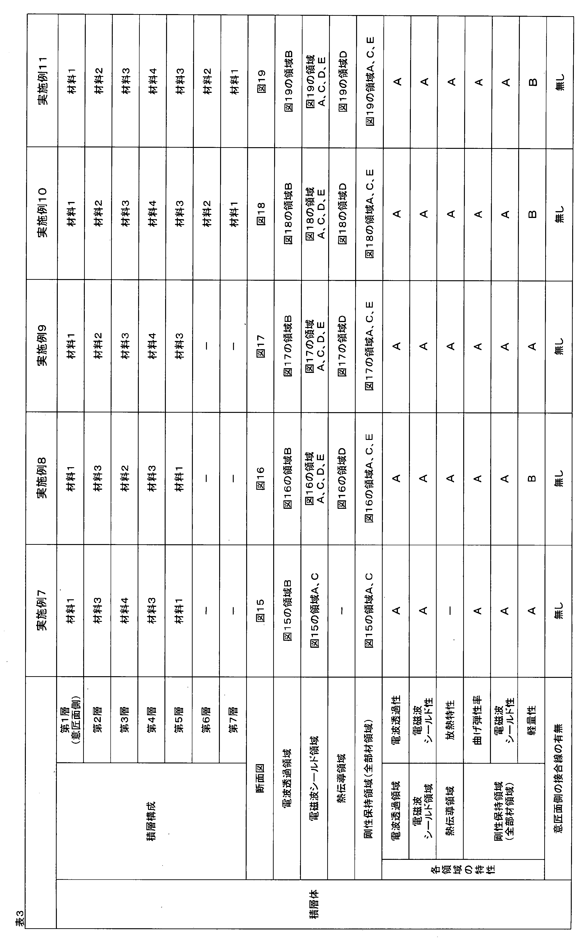
実施例1で得られたガラス繊維強化プラスチックを電波透過部材として用いて、図20に示す第1層のみからなる積層体とした。
材料2のアルミニウムシート2枚をエポキシ接着剤で貼り合わせ、図20に示す第1層のみからなる積層体を得た。積層体のアルミニウムシートは、電磁波シールド性を有する熱伝導部材に該当する。
実施例2で得られた炭素繊維強化プラスチックを、電磁波シールド性を有する剛性保持部材として用いて、図20に示す第1層のみからなる積層体とした。
材料4のポリプロピレンシート2枚をエポキシ接着剤で貼り合わせ、図20に示す第1層のみからなる積層体を得た。積層体のポリプロピレンシートは、電波透過性を有する電波透過部材に該当する。
第1層であるガラス繊維強化プラスチックを、実施例2で得られた炭素繊維強化プラスチックに変更した以外は、実施例1と同様にして、図11(a)に示す積層体を得た。なお、炭素繊維強化プラスチックは、電磁波シールド性を有する剛性保持部材に該当し、アルミニウムシートは電磁波シールド性を有する熱伝導部材に該当する。
材料2のアルミニウムシート1枚と材料3の炭素繊維強化シート4枚を用いて、炭素繊維強化シート(0°)/炭素繊維強化シート(90°)/アルミニウムシート/炭素繊維強化シート(90°)/炭素繊維強化シート(0°)の順に積層し、実施例1と同様にして加熱プレス成形し、加圧から30分間経過した後、盤面を開き、プレス成形機から、ツール板ごと取り出し、炭素繊維強化シートのエポキシ樹脂が硬化され、さらに各層間が十分に密着した、炭素繊維強化プラスチック/アルミニウムシート/炭素繊維強化プラスチックを第1~3層とする予備積層体を得た。
材料1のガラス繊維強化シート4枚と材料4のポリプロピレンシート1枚を用いて、ガラス繊維強化シート/ガラス繊維強化シート/ポリプロピレンシート/ガラス繊維強化シート/ガラス繊維強化シートの順に積層した後、実施例6と同様に加熱プレス成形および冷却プレス成形を行った後、盤面を開き、冷却プレス機から、ツール板ごと取り出し、ガラス繊維強化シートのエポキシ樹脂が硬化され、さらに各層間が十分に密着した、図22に示すようなガラス繊維強化プラスチック/ポリプロピレンシート/ガラス繊維強化プラスチックを第1~3層とする積層体を得た。なお、図22の第1層と第3層に配するガラス繊維強化プラスチックは電波透過部材に該当し、第2層に配するポリプロピレンシートは低密度部材に該当する。
材料3の炭素繊維強化シート4枚と材料4のポリプロピレンシート1枚を用いて、炭素繊維強化シート(0°)/炭素繊維強化シート(90°)/ポリプロピレンシート/炭素繊維強化シート(90°)/炭素繊維強化シート(0°)の順に積層した後、実施例6と同様に加熱プレス成形および冷却プレス成形を行った後、盤面を開き、冷却プレス機から、ツール板ごと取り出し、炭素繊維強化シートのエポキシ樹脂が硬化され、さらに各層間が十分に密着した、図22に示すような炭素繊維強化プラスチック/ポリプロピレンシート/炭素繊維強化プラスチックを第1~3層とする積層体を得た。なお、図22の第1層と第3層に配する炭素繊維強化プラスチックは電磁波シールド性を有する剛性保持部材に該当し、第2層に配するポリプロピレンシートは低密度部材に該当する。
実施例8で得られた予備積層体をそのまま用いて、図23に示すような積層体とした。なお、図23の第1層と第5層に配するガラス繊維強化プラスチックは電波透過部材に該当し、第2層と第4層に配する炭素繊維強化プラスチックは電磁波シールド性を有する剛性保持部材に該当し、第3層に配するアルミニウムシートは電磁波シールド性を有する熱伝導部材に該当する。

1a 電波透過部材の凸部
2 熱伝導部材
3 剛性保持部材
4 低密度部材
5 測定試料
6 電界シールド性の測定装置
7 信号発信用アンテナ
8 測定試料厚み
9 信号受信用アンテナ
10 金属管
11 試験片
12 発熱部材
13 アルミニウムテープ
14 断熱板
15a、15b 熱電対
Claims (16)
- 電波透過性を有する電波透過部材と、電波透過部材の厚み方向に対して電磁波シールド性を有する熱伝導部材および/または電磁波シールド性を有する剛性保持部材を積層した積層体であって、積層体の一部に、電波透過部材のみで構成された電波透過領域を有し、電波透過領域が薄肉部である、積層体。
- 積層体の一部に、熱伝導部材が露出した熱伝導領域をさらに有し、熱伝導領域が薄肉部である、請求項1に記載の積層体。
- 少なくとも1つの電波透過部材が、熱伝導部材および/または剛性保持部材に対して意匠面側に配置された、請求項1または2に記載の積層体。
- 少なくとも1つの電波透過部材が意匠面側の最表面に配置された、請求項3に記載の積層体。
- 積層体を構成する各部材が厚み方向に対称積層され、かつ熱伝導部材が厚み中央部に配置された、請求項1~4のいずれかに記載の積層体。
- 電波透過部材は、KEC法により測定される電界シールド性が周波数1GHz帯において、0dB以上20dB未満の範囲である、請求項1~5のいずれかに記載の積層体。
- 剛性保持部材および熱伝導部材は、KEC法により測定される電界シールド性が周波数1GHz帯において、20dB以上80dB以下の範囲である、請求項1~6のいずれかに記載の積層体。
- 熱伝導部材の熱伝導率が10W/m・K以上3000W/m・K以下の範囲である、請求項1~7のいずれかに記載の積層体。
- 剛性保持部材の曲げ弾性率が、電波透過部材の曲げ弾性率より高い、請求項1~8のいずれかに記載の積層体。
- 剛性保持部材が導電性繊維を含む繊維強化プラスチックで形成された、請求項1~9のいずれかに記載の積層体。
- 導電性繊維には炭素繊維が含まれる、請求項10に記載の積層体。
- 炭素繊維が連続した炭素繊維である、請求項11に記載の積層体。
- 剛性保持部材を形成する繊維強化プラスチックは、炭素繊維の繊維質量含有率が15質量%以上80質量%以下の範囲である、請求項11または12に記載の積層体。
- 電波透過部材が、有機繊維またはセラミックス繊維から選択される少なくとも1種の非導電性繊維を含む繊維強化プラスチックである、請求項1~13のいずれかに記載の積層体。
- 請求項1~14のいずれかに記載の積層体に別の部材を一体化させた、一体化成形品。
- 別の部材を射出成形により一体化させた、請求項15に記載の一体化成形品。
Priority Applications (5)
| Application Number | Priority Date | Filing Date | Title |
|---|---|---|---|
| CN201580034804.6A CN106664816B (zh) | 2014-06-30 | 2015-06-11 | 层叠体及一体化成型品 |
| KR1020177001518A KR20170023973A (ko) | 2014-06-30 | 2015-06-11 | 적층체 및 일체화 성형품 |
| EP15815551.5A EP3163996A4 (en) | 2014-06-30 | 2015-06-11 | Laminate and integrally molded article |
| JP2015530224A JP6617557B2 (ja) | 2014-06-30 | 2015-06-11 | 積層体および一体化成形品 |
| US15/320,420 US10175728B2 (en) | 2014-06-30 | 2015-06-11 | Laminate and integrally molded article |
Applications Claiming Priority (2)
| Application Number | Priority Date | Filing Date | Title |
|---|---|---|---|
| JP2014-134150 | 2014-06-30 | ||
| JP2014134150 | 2014-06-30 |
Publications (1)
| Publication Number | Publication Date |
|---|---|
| WO2016002456A1 true WO2016002456A1 (ja) | 2016-01-07 |
Family
ID=55019005
Family Applications (1)
| Application Number | Title | Priority Date | Filing Date |
|---|---|---|---|
| PCT/JP2015/066803 WO2016002456A1 (ja) | 2014-06-30 | 2015-06-11 | 積層体および一体化成形品 |
Country Status (7)
| Country | Link |
|---|---|
| US (1) | US10175728B2 (ja) |
| EP (1) | EP3163996A4 (ja) |
| JP (1) | JP6617557B2 (ja) |
| KR (1) | KR20170023973A (ja) |
| CN (1) | CN106664816B (ja) |
| TW (1) | TWI663905B (ja) |
| WO (1) | WO2016002456A1 (ja) |
Cited By (5)
| Publication number | Priority date | Publication date | Assignee | Title |
|---|---|---|---|---|
| JP2018163979A (ja) * | 2017-03-24 | 2018-10-18 | 新日鉄住金マテリアルズ株式会社 | 繊維強化複合材料成形体及びその製造方法 |
| CN109691248A (zh) * | 2016-09-26 | 2019-04-26 | 东丽株式会社 | 电子设备壳体及其制造方法 |
| JP2020530100A (ja) * | 2018-07-12 | 2020-10-15 | 同方威視技術股▲分▼有限公司 | セキュリティ検査デバイスのシールド構造及びセキュリティ検査チャネル |
| WO2021157652A1 (ja) * | 2020-02-06 | 2021-08-12 | 東レ株式会社 | 炭素繊維強化複合材料、積層炭素繊維複合材料、積層複合材料、ワイヤレス給電器向けケースおよびワイヤレス受電器向けケース |
| JP7297778B2 (ja) | 2018-03-05 | 2023-06-26 | コベストロ、ドイチュラント、アクチエンゲゼルシャフト | 熱可塑性複合品ならびにその製造方法および使用 |
Families Citing this family (11)
| Publication number | Priority date | Publication date | Assignee | Title |
|---|---|---|---|---|
| DE102013227187B4 (de) * | 2013-12-27 | 2016-08-18 | Federal-Mogul Wiesbaden Gmbh | Gleitlagerwerkstoff und Gleitlager-Verbundwerkstoff mit Zinksulfid und Bariumsulfat |
| DE102015214228A1 (de) * | 2015-07-28 | 2017-02-02 | Osram Opto Semiconductors Gmbh | Verfahren zur Herstellung eines Bauelements und ein Bauelement |
| JP6408540B2 (ja) * | 2016-12-01 | 2018-10-17 | 太陽誘電株式会社 | 無線モジュール及び無線モジュールの製造方法 |
| JP6463323B2 (ja) * | 2016-12-01 | 2019-01-30 | 太陽誘電株式会社 | 無線モジュール、およびその製造方法 |
| US10409332B2 (en) * | 2017-01-10 | 2019-09-10 | Lenovo (Singapore) Pte. Ltd. | Portable information device |
| CN111357104A (zh) * | 2017-11-20 | 2020-06-30 | 提克纳有限责任公司 | 用于在汽车中使用的电子模块 |
| KR20200079553A (ko) | 2017-11-20 | 2020-07-03 | 티코나 엘엘씨 | 전자 모듈에 사용하기 위한 섬유-강화된 중합체 조성물 |
| JP7129369B2 (ja) * | 2019-03-26 | 2022-09-01 | シャープ株式会社 | アンテナ装置および通信端末装置 |
| WO2021233026A1 (en) * | 2020-05-19 | 2021-11-25 | Antwave Intellectual Property Limited | Bendable resin having patterned elements for improving penetration of wireless communication signals |
| DE102021107096A1 (de) * | 2021-03-23 | 2022-09-29 | Bayerische Motoren Werke Aktiengesellschaft | Karosseriebauteil, Fahrzeug, Halbzeug und Verfahren zum Herstellen eines Karosseriebauteils |
| DE102021107095A1 (de) * | 2021-03-23 | 2022-09-29 | Bayerische Motoren Werke Aktiengesellschaft | Karosseriebauteil, Fahrzeug, Halbzeug und Verfahren zum Herstellen eines Karosseriebauteils |
Citations (7)
| Publication number | Priority date | Publication date | Assignee | Title |
|---|---|---|---|---|
| JPH0690069A (ja) * | 1990-09-27 | 1994-03-29 | Sun Microsyst Inc | プリント回路基板アセンブリ及びそれに熱導伝路を形成させる方法 |
| JP2000184316A (ja) * | 1998-12-21 | 2000-06-30 | Seiko Epson Corp | 通信用アンテナを備えた電子機器 |
| JP2008177275A (ja) * | 2007-01-17 | 2008-07-31 | Sony Ericsson Mobilecommunications Japan Inc | 放熱構造体及び携帯端末 |
| JP2010253937A (ja) * | 2009-03-31 | 2010-11-11 | Toray Ind Inc | 一体化成形品 |
| JP2013086469A (ja) * | 2011-10-21 | 2013-05-13 | Shin Etsu Polymer Co Ltd | 電波透過性装飾部材およびその製造方法 |
| JP2014060237A (ja) * | 2012-09-18 | 2014-04-03 | Nec Corp | 加飾フィルム、それを備えた筐体及びその製造方法 |
| WO2014065261A1 (ja) * | 2012-10-23 | 2014-05-01 | 三菱レイヨン株式会社 | 繊維強化複合材料成形体およびその製造方法 |
Family Cites Families (11)
| Publication number | Priority date | Publication date | Assignee | Title |
|---|---|---|---|---|
| US5965847A (en) * | 1996-11-12 | 1999-10-12 | Sumitomo Wiring Systems, Ltd. | Shield connector |
| US6905634B2 (en) * | 1998-10-13 | 2005-06-14 | Peter Burnell-Jones | Heat curable thermosetting luminescent resins |
| TWI304321B (en) * | 2002-12-27 | 2008-12-11 | Toray Industries | Layered products, electromagnetic wave shielding molded articles and method for production thereof |
| JP2008034823A (ja) * | 2006-06-30 | 2008-02-14 | Toray Ind Inc | 電子機器筐体およびその製造方法 |
| JP2010242055A (ja) * | 2009-03-19 | 2010-10-28 | Asahi Kasei Chemicals Corp | ポリエチレン系樹脂製無架橋押出発泡シート |
| JP2011093213A (ja) | 2009-10-30 | 2011-05-12 | Toray Ind Inc | 繊維強化プラスチック製電子機器筐体の製造方法 |
| CN102416743A (zh) * | 2009-12-02 | 2012-04-18 | 上海科斗电子科技有限公司 | 基体中埋设有导电纤维毡的塑料制品 |
| US9260645B2 (en) * | 2010-02-23 | 2016-02-16 | Laird Technologies, Inc. | Thermal interface materials including thermally reversible gels |
| JP2013075447A (ja) | 2011-09-30 | 2013-04-25 | Toray Ind Inc | 複合積層板および複合積層板を用いた一体成形品ならびにそれらの製造方法 |
| CN102651948A (zh) * | 2011-12-30 | 2012-08-29 | 洛阳理工学院 | 一种电器外壳材料及其制备方法 |
| US9786979B2 (en) * | 2014-01-14 | 2017-10-10 | Dell Products L.P. | Composite chassis wall with wireless transmission window |
-
2015
- 2015-06-11 KR KR1020177001518A patent/KR20170023973A/ko unknown
- 2015-06-11 US US15/320,420 patent/US10175728B2/en not_active Expired - Fee Related
- 2015-06-11 WO PCT/JP2015/066803 patent/WO2016002456A1/ja active Application Filing
- 2015-06-11 JP JP2015530224A patent/JP6617557B2/ja not_active Expired - Fee Related
- 2015-06-11 EP EP15815551.5A patent/EP3163996A4/en not_active Withdrawn
- 2015-06-11 CN CN201580034804.6A patent/CN106664816B/zh not_active Expired - Fee Related
- 2015-06-29 TW TW104120879A patent/TWI663905B/zh not_active IP Right Cessation
Patent Citations (7)
| Publication number | Priority date | Publication date | Assignee | Title |
|---|---|---|---|---|
| JPH0690069A (ja) * | 1990-09-27 | 1994-03-29 | Sun Microsyst Inc | プリント回路基板アセンブリ及びそれに熱導伝路を形成させる方法 |
| JP2000184316A (ja) * | 1998-12-21 | 2000-06-30 | Seiko Epson Corp | 通信用アンテナを備えた電子機器 |
| JP2008177275A (ja) * | 2007-01-17 | 2008-07-31 | Sony Ericsson Mobilecommunications Japan Inc | 放熱構造体及び携帯端末 |
| JP2010253937A (ja) * | 2009-03-31 | 2010-11-11 | Toray Ind Inc | 一体化成形品 |
| JP2013086469A (ja) * | 2011-10-21 | 2013-05-13 | Shin Etsu Polymer Co Ltd | 電波透過性装飾部材およびその製造方法 |
| JP2014060237A (ja) * | 2012-09-18 | 2014-04-03 | Nec Corp | 加飾フィルム、それを備えた筐体及びその製造方法 |
| WO2014065261A1 (ja) * | 2012-10-23 | 2014-05-01 | 三菱レイヨン株式会社 | 繊維強化複合材料成形体およびその製造方法 |
Cited By (8)
| Publication number | Priority date | Publication date | Assignee | Title |
|---|---|---|---|---|
| CN109691248A (zh) * | 2016-09-26 | 2019-04-26 | 东丽株式会社 | 电子设备壳体及其制造方法 |
| EP3518633A4 (en) * | 2016-09-26 | 2020-04-29 | Toray Industries, Inc. | ELECTRONIC DEVICE HOUSING AND METHOD FOR PRODUCING THE SAME |
| CN109691248B (zh) * | 2016-09-26 | 2021-07-30 | 东丽株式会社 | 电子设备壳体及其制造方法 |
| JP2018163979A (ja) * | 2017-03-24 | 2018-10-18 | 新日鉄住金マテリアルズ株式会社 | 繊維強化複合材料成形体及びその製造方法 |
| JP7297778B2 (ja) | 2018-03-05 | 2023-06-26 | コベストロ、ドイチュラント、アクチエンゲゼルシャフト | 熱可塑性複合品ならびにその製造方法および使用 |
| JP2020530100A (ja) * | 2018-07-12 | 2020-10-15 | 同方威視技術股▲分▼有限公司 | セキュリティ検査デバイスのシールド構造及びセキュリティ検査チャネル |
| US11385377B2 (en) | 2018-07-12 | 2022-07-12 | Nuctech Company Limited | Shielding structure of safety inspection equipment and safety inspection channel |
| WO2021157652A1 (ja) * | 2020-02-06 | 2021-08-12 | 東レ株式会社 | 炭素繊維強化複合材料、積層炭素繊維複合材料、積層複合材料、ワイヤレス給電器向けケースおよびワイヤレス受電器向けケース |
Also Published As
| Publication number | Publication date |
|---|---|
| TWI663905B (zh) | 2019-06-21 |
| EP3163996A1 (en) | 2017-05-03 |
| CN106664816B (zh) | 2020-02-28 |
| US10175728B2 (en) | 2019-01-08 |
| JPWO2016002456A1 (ja) | 2017-04-27 |
| CN106664816A (zh) | 2017-05-10 |
| US20170185108A1 (en) | 2017-06-29 |
| KR20170023973A (ko) | 2017-03-06 |
| TW201608962A (zh) | 2016-03-01 |
| JP6617557B2 (ja) | 2019-12-11 |
| EP3163996A4 (en) | 2018-01-10 |
Similar Documents
| Publication | Publication Date | Title |
|---|---|---|
| JP6617557B2 (ja) | 積層体および一体化成形品 | |
| WO2016002457A1 (ja) | 積層体および一体化成形品 | |
| TWI781970B (zh) | 一體成形體及其製造方法 | |
| CN108290374B (zh) | 夹层结构体及成型体、以及它们的制造方法 | |
| US10908651B2 (en) | Electronic device housing | |
| JP4670532B2 (ja) | 複合成形品 | |
| JP4858544B2 (ja) | 複合成形品およびその製造方法 | |
| JP5776137B2 (ja) | 一体化成形品の製造方法 | |
| JP3906319B2 (ja) | 積層体、一体化成形品、および、それらの製造方法 | |
| JP6167537B2 (ja) | 繊維強化プラスチック成形品の製造方法および一体成形品の製造方法 | |
| JP4023515B2 (ja) | 熱接着用基材が用いられてなるプリフォーム、および積層体の製造方法 | |
| WO2011086959A1 (ja) | 射出成形品およびその製造方法 | |
| JP2008034823A (ja) | 電子機器筐体およびその製造方法 | |
| JP2013075447A (ja) | 複合積層板および複合積層板を用いた一体成形品ならびにそれらの製造方法 | |
| US10571963B2 (en) | Housing | |
| JP2007110138A (ja) | 電磁波シールド成形品、および、その製造方法 | |
| JP2011093213A (ja) | 繊維強化プラスチック製電子機器筐体の製造方法 | |
| JP2009220478A (ja) | 繊維強化サンドイッチ構造複合体、複合成形体 | |
| WO2023248914A1 (ja) | 一体化成形体及び電子機器筐体 | |
| WO2023276848A1 (ja) | 一体化成形体 | |
| EP3846993B1 (en) | Method for the production of a molded composite article | |
| JP2004358828A (ja) | 繊維強化熱硬化樹脂製筐体成形品およびその製造方法 | |
| JP2010046938A (ja) | 複合成形品およびその製造方法 | |
| EP3650191A1 (en) | Molded composite article, method for the production thereof and use thereof | |
| EP3771959A1 (en) | Portable electronic device housings having hybrid laminate sidewalls and methods of making the same |
Legal Events
| Date | Code | Title | Description |
|---|---|---|---|
| ENP | Entry into the national phase |
Ref document number: 2015530224 Country of ref document: JP Kind code of ref document: A |
|
| 121 | Ep: the epo has been informed by wipo that ep was designated in this application |
Ref document number: 15815551 Country of ref document: EP Kind code of ref document: A1 |
|
| WWE | Wipo information: entry into national phase |
Ref document number: 15320420 Country of ref document: US |
|
| NENP | Non-entry into the national phase |
Ref country code: DE |
|
| ENP | Entry into the national phase |
Ref document number: 20177001518 Country of ref document: KR Kind code of ref document: A |
|
| REEP | Request for entry into the european phase |
Ref document number: 2015815551 Country of ref document: EP |
|
| WWE | Wipo information: entry into national phase |
Ref document number: 2015815551 Country of ref document: EP |