WO2016002449A1 - 回転移動検出装置 - Google Patents
回転移動検出装置 Download PDFInfo
- Publication number
- WO2016002449A1 WO2016002449A1 PCT/JP2015/066721 JP2015066721W WO2016002449A1 WO 2016002449 A1 WO2016002449 A1 WO 2016002449A1 JP 2015066721 W JP2015066721 W JP 2015066721W WO 2016002449 A1 WO2016002449 A1 WO 2016002449A1
- Authority
- WO
- WIPO (PCT)
- Prior art keywords
- magnet
- rotation
- hole
- rotating member
- lever
- Prior art date
- Legal status (The legal status is an assumption and is not a legal conclusion. Google has not performed a legal analysis and makes no representation as to the accuracy of the status listed.)
- Ceased
Links
Images






Classifications
-
- B—PERFORMING OPERATIONS; TRANSPORTING
- B60—VEHICLES IN GENERAL
- B60Q—ARRANGEMENT OF SIGNALLING OR LIGHTING DEVICES, THE MOUNTING OR SUPPORTING THEREOF OR CIRCUITS THEREFOR, FOR VEHICLES IN GENERAL
- B60Q1/00—Arrangement of optical signalling or lighting devices, the mounting or supporting thereof or circuits therefor
- B60Q1/02—Arrangement of optical signalling or lighting devices, the mounting or supporting thereof or circuits therefor the devices being primarily intended to illuminate the way ahead or to illuminate other areas of way or environments
- B60Q1/04—Arrangement of optical signalling or lighting devices, the mounting or supporting thereof or circuits therefor the devices being primarily intended to illuminate the way ahead or to illuminate other areas of way or environments the devices being headlights
- B60Q1/14—Arrangement of optical signalling or lighting devices, the mounting or supporting thereof or circuits therefor the devices being primarily intended to illuminate the way ahead or to illuminate other areas of way or environments the devices being headlights having dimming means
- B60Q1/1446—Arrangement of optical signalling or lighting devices, the mounting or supporting thereof or circuits therefor the devices being primarily intended to illuminate the way ahead or to illuminate other areas of way or environments the devices being headlights having dimming means controlled by mechanically actuated switches
- B60Q1/1453—Hand actuated switches
- B60Q1/1461—Multifunction switches for dimming headlights and controlling additional devices, e.g. for controlling direction indicating lights
- B60Q1/1469—Multifunction switches for dimming headlights and controlling additional devices, e.g. for controlling direction indicating lights controlled by or attached to a single lever, e.g. steering column stalk switches
-
- H—ELECTRICITY
- H01—ELECTRIC ELEMENTS
- H01H—ELECTRIC SWITCHES; RELAYS; SELECTORS; EMERGENCY PROTECTIVE DEVICES
- H01H25/00—Switches with compound movement of handle or other operating part
- H01H25/04—Operating part movable angularly in more than one plane, e.g. joystick
-
- G—PHYSICS
- G01—MEASURING; TESTING
- G01D—MEASURING NOT SPECIALLY ADAPTED FOR A SPECIFIC VARIABLE; ARRANGEMENTS FOR MEASURING TWO OR MORE VARIABLES NOT COVERED IN A SINGLE OTHER SUBCLASS; TARIFF METERING APPARATUS; MEASURING OR TESTING NOT OTHERWISE PROVIDED FOR
- G01D5/00—Mechanical means for transferring the output of a sensing member; Means for converting the output of a sensing member to another variable where the form or nature of the sensing member does not constrain the means for converting; Transducers not specially adapted for a specific variable
- G01D5/12—Mechanical means for transferring the output of a sensing member; Means for converting the output of a sensing member to another variable where the form or nature of the sensing member does not constrain the means for converting; Transducers not specially adapted for a specific variable using electric or magnetic means
- G01D5/14—Mechanical means for transferring the output of a sensing member; Means for converting the output of a sensing member to another variable where the form or nature of the sensing member does not constrain the means for converting; Transducers not specially adapted for a specific variable using electric or magnetic means influencing the magnitude of a current or voltage
-
- G—PHYSICS
- G01—MEASURING; TESTING
- G01D—MEASURING NOT SPECIALLY ADAPTED FOR A SPECIFIC VARIABLE; ARRANGEMENTS FOR MEASURING TWO OR MORE VARIABLES NOT COVERED IN A SINGLE OTHER SUBCLASS; TARIFF METERING APPARATUS; MEASURING OR TESTING NOT OTHERWISE PROVIDED FOR
- G01D5/00—Mechanical means for transferring the output of a sensing member; Means for converting the output of a sensing member to another variable where the form or nature of the sensing member does not constrain the means for converting; Transducers not specially adapted for a specific variable
- G01D5/12—Mechanical means for transferring the output of a sensing member; Means for converting the output of a sensing member to another variable where the form or nature of the sensing member does not constrain the means for converting; Transducers not specially adapted for a specific variable using electric or magnetic means
- G01D5/14—Mechanical means for transferring the output of a sensing member; Means for converting the output of a sensing member to another variable where the form or nature of the sensing member does not constrain the means for converting; Transducers not specially adapted for a specific variable using electric or magnetic means influencing the magnitude of a current or voltage
- G01D5/142—Mechanical means for transferring the output of a sensing member; Means for converting the output of a sensing member to another variable where the form or nature of the sensing member does not constrain the means for converting; Transducers not specially adapted for a specific variable using electric or magnetic means influencing the magnitude of a current or voltage using Hall-effect devices
- G01D5/145—Mechanical means for transferring the output of a sensing member; Means for converting the output of a sensing member to another variable where the form or nature of the sensing member does not constrain the means for converting; Transducers not specially adapted for a specific variable using electric or magnetic means influencing the magnitude of a current or voltage using Hall-effect devices influenced by the relative movement between the Hall device and magnetic fields
-
- H—ELECTRICITY
- H01—ELECTRIC ELEMENTS
- H01H—ELECTRIC SWITCHES; RELAYS; SELECTORS; EMERGENCY PROTECTIVE DEVICES
- H01H19/00—Switches operated by an operating part which is rotatable about a longitudinal axis thereof and which is acted upon directly by a solid body external to the switch, e.g. by a hand
Definitions
- the present invention relates to a rotational movement detection device.
- first rotating body and a second rotating body that rotate in response to the swinging operation of the outer lever, and two magnets provided in correspondence to the magnets of the two magnets mounted in the center.
- a lever switch device having a configuration in which the detection means detects a rotation angle of each rotating body from the detection signal and outputs an operation signal in accordance with the detection signal (for example, Patent Document 1). reference).
- the lever switch device described in Patent Document 1 has a backlash of the first rotating body and the second rotating body, but there is a possibility that the detection accuracy is lowered.
- An object of the present invention is to provide a rotational movement detection device that improves the detection accuracy by suppressing the rattling of a rotating member.
- a rotational movement detection device has a through hole penetrating from a first surface to a second surface opposite to the first surface, rotates around the through hole, and generates a magnetic field around it.
- a rotation member to be generated a rotation angle detection unit that detects a rotation angle of the rotation member, a movement detection unit that detects movement of the rotation member along the rotation axis, and a rotation member inserted into the through hole to guide the rotation of the rotation member
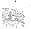
- FIG. 1 is an explanatory diagram showing the interior of a vehicle on which a lever switch device according to an embodiment of the present invention is mounted.
- FIG. 2 is a perspective view showing an appearance of the lever switch device.
- FIG. 3 is an exploded perspective view showing the lever switch device.
- 4 is a cross-sectional view taken along the line AA in FIG.
- FIG. 5A is a perspective view showing the magnetizing direction of the magnet, the state of magnetic flux, and the positional relationship of the turn detection sensor.
- 5B is a cross-sectional view taken along line EE of FIG. 5A.
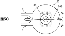
- FIG. 5C is a plan view showing the positional relationship between the state of magnetic flux and the turn detection sensor as viewed from the direction F in FIG. 5A.
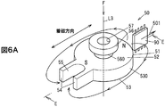
- FIG. 6A is a perspective view showing the magnetizing direction of the magnet, the state of magnetic flux, and the positional relationship of the dimmer detection sensor.
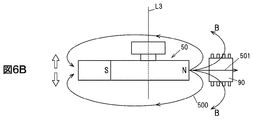
- 6B is a cross-sectional view taken along line EE of FIG. 6A.
- FIG. 6C is a plan view showing the positional relationship between the state of magnetic flux and the dimmer detection sensor as seen from the direction F in FIG. 6A.
- 7 is a cross-sectional view corresponding to the GG cross-sectional view of FIG. 3 and the EE cross-sectional view of FIG. 5A showing the magnet holder and the magnet according to the embodiment of the present invention, respectively.
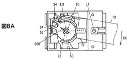
- FIG. 8A is a plan view showing a state of movement of the lever and magnet during a right turn operation (operation in the direction of arrow TR) seen from the direction B of FIG.
- FIG. 8B is a plan view showing a state of movement of the lever and magnet in the neutral position as seen from the direction B of FIG.
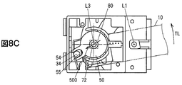
- FIG. 8C is a plan view showing the moving state of the lever and magnet during the left turn operation (operation in the arrow TL direction) as seen from the direction B of FIG. 8A to 8C are plan views viewed from the direction B with the upper housing removed.
- FIG. 9A is a circuit diagram illustrating an example of a magnetic sensor.
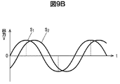
- FIG. 9B is a signal waveform diagram showing detection signals S1 and S2 detected by the first MR bridge and the second MR bridge.
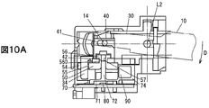
- FIG. 10A is a partial cross-sectional view showing the moving state of the lever and magnet during the dimmer operation in the AA cross section of FIG.
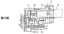
- FIG. 10B is a partial cross-sectional view showing the state of movement of the lever and magnet in the neutral position in the AA cross section of FIG.
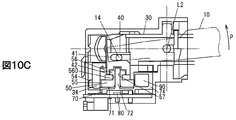
- FIG. 10C is a partial cross-sectional view showing the moving state of the lever and magnet during the passing operation in the AA cross section of FIG.
- the rotational movement detection device has a through-hole penetrating from the first surface to the second surface opposite to the first surface, and rotates around the through-hole to generate a magnetic field around it.
- a rotation member to be rotated a rotation angle detection unit that detects a rotation angle of the rotation member, a movement detection unit that detects movement of the rotation member along the rotation axis, and a rotation member that is inserted into the through hole to guide the rotation of the rotation member
- FIG. 1 is an explanatory diagram showing the interior of a vehicle on which a lever switch device according to an embodiment of the present invention is mounted.
- FIG. 2 is a perspective view showing an appearance of the lever switch device.
- the lever switch device 1 as a rotational movement detection device is an operation device capable of operating a turn signal (direction indicator) or a headlamp of the vehicle 5, for example. As shown in FIG. 1, the lever switch device 1 is mounted in the vicinity of the steering 6 of the vehicle, and is disposed so as to protrude from a steering column cover 7 that covers the steering column.
- the lever switch device 1 disposed so as to protrude rightward on the paper surface of FIG. 1 operates, for example, a direction indicator and a headlamp.
- a lever switch device 1 capable of operating a direction indicator and the like protruding to the right side on the premise of a right-hand drive vehicle will be described.
- the lever switch device 1 has a through hole (through hole 57) penetrating from the first surface (upper surface 52) to the second surface (lower surface 53) opposite to the first surface. ), Rotating around the through-hole and generating a magnetic field around it (magnet 50), a rotation angle detector (turn detection sensor 80) for detecting the rotation angle of the rotation member, A movement detection unit (dima detection sensor 90) that detects movement along the rotation axis, a guide unit (magnet support shaft 72) that is inserted into the through hole to guide the rotation of the rotation member and holds the rotation member, and rotation A holding portion (magnet holder 70) integrated with an arrangement portion (attachment portion 74) on which the movement detection portion is arranged facing the side surface of the member.
- the lever switch device 1 is configured to perform a first rotation operation about the first rotation axis L1 and a second rotation operation about the second rotation axis L2 intersecting the first rotation axis L1.
- a possible operation unit a first conversion unit that converts the first rotation operation performed on the operation unit into a rotation around the third rotation axis L3 of the magnet 50, and a second rotation operation performed on the operation unit And a second conversion unit that converts relative movement between the magnet 50 and the arrangement surface 101.
- the operation unit is an operation lever 10 as an example.
- the 1st conversion part is bracket 30 as an example.
- the 2nd conversion part is holder 40 as an example.
- the lever switch apparatus 1 has the housing
- the direction of the first rotation operation around the first rotation axis L1 shown in FIG. 3 indicates the operation in the arrow TL direction shown in FIG. 2 and the operation in the arrow TR direction which is opposite to the arrow TL direction. ing.
- the operation in the direction of the arrow TL is, for example, a left turn operation for blinking the left turn signal (direction indicator) of the vehicle 5.
- the operation in the direction of the arrow TR is, for example, a right turn operation for blinking the right turn signal (direction indicator). That is, the first rotation operation is a winker (direction indicator) operation for left or right turn, and is a turn operation of the operation lever 10.
- the direction of the second rotation operation around the second rotation axis L2 shown in FIG. 3 indicates the operation in the arrow D direction shown in FIG. 2 and the operation in the arrow P direction opposite to the arrow D direction.
- the operation in the direction of arrow D is, for example, an operation (dimmer HU operation) for switching the optical axis of the headlamp of the vehicle 5 upward.
- the operation in the arrow P direction is, for example, an operation (passing operation) for switching the optical axis of the headlight upward while maintaining the operation.
- the lever switch device 1 is configured as a momentary switch that returns to the neutral position after the operation is completed for the operation in the direction of the arrow P.
- the lever switch device 1 does not return to the neutral position after the operation is completed, but maintains the state in which the operation lever 10 is operated in the direction of the arrow D. It is configured. That is, the second rotation operation is an operation of switching the optical axis of the headlamp, and is a dimmer operation of the operation lever 10.
- the first operation direction described above is operated in the vertical direction of FIG. 2 as viewed from the operator. It becomes the direction to do.
- the upward operation is an operation in the arrow TL direction
- the downward operation is an operation in the arrow TR direction.
- the second operation direction is a direction to operate in the front-rear direction as viewed from the operator.
- This forward operation is an operation in the direction of arrow P, and is an operation that pulls the operation lever 10 toward the operator.
- the backward operation is an operation in the direction of arrow D, and is an operation that moves the operation lever 10 away from the operator.
- the operation surface formed by the operation lever 10 by the operation in the arrow TL direction and the arrow TR direction intersects with the operation surface formed by the operation lever 10 by the operation in the arrow D direction and the arrow P direction. Orthogonal.
- the operation lever 10 is accommodated in the bracket 30 and can be rotated around the first rotation axis L1 integrally with the bracket 30 by a first rotation operation (turn operation), and intersects the first rotation axis L1. And configured to be capable of rotating and moving independently of the bracket 30 in the direction of the second rotation operation (dimmer operation) around the second rotation axis L2.
- the operation lever 10 includes an insertion portion 11 that is inserted and accommodated in the bracket 30, a lever main body 12 that is held by an operator for turn operation and dimmer operation, and between the insertion portion 11 and the lever main body 12. It has a rotation shaft portion 13 that is positioned and serves as a second rotation shaft L2 that is the rotation center of the dimmer operation of the operation lever 10.
- the rotary shaft portion 13 is formed to protrude in both directions of the second rotary shaft L ⁇ b> 2, and the insertion portion 11 is inserted into the bracket 30, whereby the support hole portion 33 of the bracket 30. Is rotatably supported.
- a driving projection 14 is formed to protrude so as to engage with a holder 40 described later and slide the holder 40 during a dimmer operation.
- An insertion hole 15 into which the moderation piece 16 is inserted via a spring 17 is formed at the distal end of the insertion portion 11.
- the moderation piece 16 is urged toward the moderation block 25 by the spring 17 in a state where the operation lever 10 is assembled to the bracket 30 and the housing 20. Thereby, the moderation feeling required at the time of turn operation and dimmer operation can be provided.
- the housing 20 includes an upper housing 21 and a lower housing 22 as shown in FIGS.
- a moderation block 25 is attached to the upper housing 21 corresponding to the moderation piece 16.
- the magnet holder 70 and the substrate 100 are fixed to the lower housing 22 from below.
- the upper housing 21 and the lower housing 22 are locked and fixed to each other by the engagement of the locking portion 21a and the locking projection 22a.
- the upper housing 21 has a box shape that can accommodate the bracket 30 and the like therein. As shown in FIG. 4, a support hole portion 21 b that rotatably supports the rotating shaft portion 31 of the bracket 30 is formed on the inner upper surface.
- the upper housing 21 rotatably supports the upper portion of the bracket 30, and the lower housing 22 rotatably supports the lower portion of the bracket 30 so that the bracket 30 is sandwiched between the upper housing 21 and the lower housing 22.
- Accommodate Inside the upper housing 21, an internal space is formed so that the bracket 30 can be rotated and moved around the support hole portion 21b by a predetermined angle (an angle necessary for the turn operation).
- a moderation block 25 is mounted inside the upper housing 21 as shown in FIG.
- the moderation block 25 gives a feeling of moderation required at the time of turn operation and dimmer operation by the urged moderation piece 16 and the moderation groove 25a.
- the lower housing 22 has a box shape that can accommodate the bracket 30 and the like therein. As shown in FIG. 4, an annular groove portion 22 b that rotatably supports the annular wall portion 32 of the bracket 30 is formed on the inner lower surface. Similar to the upper casing 21, an inner space is formed in the lower casing 22 so that the bracket 30 can rotate and move around the annular groove 22b by a predetermined angle (an angle necessary for the turn operation).
- the magnet holder 70 and the substrate 100 are fixed to the lower housing 22 from the lower side.
- bracket 30 (Configuration of bracket 30)
- the bracket 30 is formed with a rotating shaft portion 31 protruding from the first rotating shaft L1, and an annular wall portion 32 is formed as shown in FIG. Thereby, the bracket 30 is accommodated in the housing 20 in a state in which the bracket 30 can be rotated about the first rotation axis L1 by a predetermined angle (an angle necessary for the turn operation).
- the bracket 30 is formed with a support hole portion 33 that is rotatably fitted to and supported by the rotation shaft portion 13 of the operation lever 10 on the second rotation shaft L2. As a result, the bracket 30 accommodates the operation lever 10 in a state in which the bracket 30 can rotate and move independently of the bracket 30 in the direction of the second rotation operation (dimmer operation) around the second rotation axis L2.
- the bracket 30 is formed with a drive projection 34 for rotationally driving a magnet 50 described later at a position separated from the first rotation axis L1.
- the drive protrusion 34 is rotated by a predetermined angle together with the bracket 30 around the first rotation axis L ⁇ b> 1 by the first rotation operation (turn operation) of the operation lever 10.
- the holder 40 can be rotated around the first rotation axis L1 integrally with the bracket 30 by the first rotation operation (turn operation) of the operation lever 10, and the second rotation operation (dimma) of the operation lever 10 can be performed.
- the bracket 30 is housed in the bracket 30 so as to be slidable with respect to the bracket 30 by operation.
- the holder 40 is formed with a fitting groove 41 in the upper portion of the holder 40 in which the drive protrusion 14 of the operation lever 10 is fitted.
- the fitting groove 41 is configured so that the holder 40 follows the vertical movement of the drive protrusion 14 when the operation lever 10 is rotated around the second rotation axis L2 (dimmer operation). It is formed as a groove not to follow the movement in the direction intersecting the second rotation axis L2.
- the holder 40 has a magnet 50 placed below the holder 40 when the operation lever 10 is rotated around the second rotation axis L ⁇ b> 2 (dimmer operation).
- a holding groove 42 for holding and moving up and down is formed.
- the holding groove 42 prevents the operation lever 10 from following the movement around the first rotation axis L1 when the first rotation operation (turn operation) is performed around the first rotation axis L1. It is formed as a groove.
- FIG. 5A is a perspective view showing the magnetization direction of the magnet, the state of magnetic flux, and the positional relationship of the turn detection sensor
- FIG. 5B is a cross-sectional view taken along line EE of FIG. 5A
- FIG. 5C is viewed from the F direction of FIG.
- FIG. 5 is a plan view showing a state of magnetic flux and a positional relationship between a turn detection sensor 80.
- 6A is a perspective view showing the magnetization direction of the magnet, the state of magnetic flux, and the positional relationship of the dimmer detection sensor
- FIG. 6B is a cross-sectional view taken along line EE in FIG. 6A
- FIG. 6C is viewed from the F direction in FIG.
- FIG. 5 is a plan view showing a positional relationship between a state of magnetic flux and a dimmer detection sensor 90.
- the magnet 50 is, for example, a permanent magnet such as an alnico magnet, a ferrite magnet, or a neodymium magnet, or a magnetic material such as a ferrite-based, neodymium-based, samakoba-based, or samarium-iron-nitrogen-based material, and a polystyrene-based, polyethylene-based, polyamide-based, It is a plastic magnet formed by mixing a synthetic resin material such as acrylonitrile / butadiene / styrene (ABS) into a desired shape. In the present embodiment, the magnet 50 uses a plastic magnet.
- ABS acrylonitrile / butadiene / styrene
- the magnet 50 has a donut shape provided with a through hole 57. Specifically, as shown in FIG. 3, FIG. 5A, etc., the magnet 50 has a shape in which a disc portion 51 and a cylindrical portion 56 are coaxially stacked on the upper surface 52 with a circumferential groove portion 560 interposed therebetween. A through hole 57 penetrating along the rotation axis L3 is formed. Further, two projecting portions 54 are formed to project from one of the disk portions 51 in the radial direction, and a recess 55 into which the drive projecting portion 34 of the bracket 30 is fitted is formed between the two projecting portions 54. Is formed.
- the magnetizing direction of the magnet 50 is perpendicular to the third rotation axis L3 and is the direction in which the protruding portion 54 is formed.
- the protruding portion 54 side becomes the S pole and the opposite side of the protruding portion 54 becomes the N pole.
- Magnetization with reverse polarity is also possible.
- typical magnetic flux is radiated from the N pole of the magnet 50 toward the S pole, and the magnetic flux radiated from the N pole in the radial direction is magnetized.
- the magnetic flux 500 converged on the south pole through the lower side of the disc portion 51 is formed.
- FIG. 7 is a cross-sectional view corresponding to the GG cross-sectional view of FIG. 3 and the EE cross-sectional view of FIG. 5A showing the magnet holder and the magnet according to the embodiment of the present invention, respectively.
- FIG. 7 shows a state where the magnet 50 is attached to the magnet holder 70.
- the magnet holder 70 is positioned and fixed to the lower housing 22 while being fixed to the substrate 100 by a plurality of legs 75.
- the magnet holder 70 has a bottom 71, a magnet support shaft 72 formed to project from the bottom 71 toward the magnet 50, and a projecting toward the magnet 50 from the bottom 71 and concentric with the magnet support shaft 72.
- a wall portion 73 formed in a shape, a mounting portion 74 for attaching the dimmer detection sensor 90, and the like.
- the magnet holder 70 is integrally formed of resin (nonmagnetic material).
- the magnet support shaft 72 is formed to fit in the through hole 57 of the magnet 50 so as to be rotatable and slidable, and the operation lever 10 is subjected to a second rotation operation (dima operation) around the second rotation axis L2.
- the magnet 50 is supported to move up and down on the third rotation axis L3.
- the wall portion 73 is provided along the outer periphery of the magnet 50, but the magnet 50 is mainly supported by the magnet support shaft 72.
- a storage space 710 is provided below the bottom 71 on the paper surface of FIG. In the storage space 710, a turn detection sensor 80 disposed on the placement surface 101 of the substrate 100 is located.
- the magnet support shaft 72 is inserted into the through hole 57 of the magnet 50 and supports the magnet 50 so as to be rotatable.
- a gap ⁇ g between a side surface 510 of the magnet 50 in which the magnet support shaft 72 is inserted and an MR sensor unit 900 described later disposed in the mounting portion 74 is a movement along the third rotation axis L3 of the magnet 50.
- the design value is assumed. As an example, the design value is 2.0 mm ⁇ 0.5 mm ( ⁇ g ⁇ ⁇ s).
- ⁇ s is a tilt ⁇ T caused by at least the distance d between the magnet support shaft 72 and the mounting portion 74 and the difference between the diameter of the magnet support shaft 72 and the diameter of the through hole 57 of the magnet 50.
- ⁇ s is 0.4 to 1.0 mm, more preferably 0.5 to 0.7 mm in consideration of distance L and tilt ⁇ T.
- the magnet 50 is not supported by the wall portion 73 of the magnet holder 70, but the magnet 50 is inserted into a donut shape, that is, the magnet support shaft 72 is inserted into the through hole 57 corresponding to the third rotation axis L3. Since the magnet 50 is rotatably supported, the accuracy of the gap ⁇ g can be increased.
- the mounting portion 74 has a plurality of lead frames 701 integrated by insert molding. Terminals 703 of the lead frame 701 are exposed to the outside of the mounting portion 74, inserted into via holes formed in the substrate 100, and electrically connected to the wiring 102 of the substrate 100 with solder or the like.
- a later-described MR sensor unit 900 of the dimmer detection sensor 90 is attached to the mounting unit 702 of the lead frame 701 with a conductive adhesive or the like, and is electrically connected to another lead frame 701 by wire bonding, for example. .
- the operation lever 10, the housing 20, the bracket 30, and the holder 40 described above are disposed near the magnet 50, it is preferable that the operation lever 10, the housing 20, the bracket 30, and the holder 40 be formed of a nonmagnetic material such as resin.
- the magnetic sensors as detection units are a turn detection sensor 80 and a dimmer detection sensor 90.
- the turn detection sensor 80 and the dimmer detection sensor 90 are both MR (Magneto Resistive) sensors using magnetoresistive elements.
- MR Magnetic Resistive
- a Hall sensor using a Hall element or the like can be used.
- the turn detection sensor 80 and the dimmer detection sensor 90 are packaged as one chip including an amplification unit that amplifies a signal and a processing unit that processes a signal
- the MR sensor is configured by a plurality of MR elements. May be placed in places other than the center of the chip.
- the turn detection sensor 80 has an MR sensor unit 800 and the dimmer detection sensor 90 has an MR sensor unit 900.
- the turn detection sensor 80 is arranged so that the sensor center of the MR sensor unit 800 and the third rotation axis L3 coincide.
- the dimmer detection sensor 90 is arranged so that the sensor center of the MR sensor unit 900 coincides with the center of the side surface 510 of the magnet 50 in the neutral state.
- the sensor center is, for example, the center of the bridge circuit when a bridge circuit is formed by four MR elements, and the center of the detection surface in the case of a Hall element.
- the turn detection sensor 80 is disposed in the storage space 710 below the magnet 50 on the third rotation axis L ⁇ b> 3. As shown in FIGS. 4 and 5A, the turn detection sensor 80 is positioned and fixed to the lower housing 22 in a state where it is mounted on the substrate 100 that is separated from the lower surface 53 of the magnet 50 by a predetermined distance.
- the typical magnetic flux of the magnet 50 is radiated from the N pole of the magnet 50 toward the S pole, and the magnetic flux radiated from the N pole in the radial direction is the circle of the magnet 50.
- a magnetic flux 500 that converges on the south pole through the lower side of the plate portion 51 is formed.
- the turn detection sensor 80 is arranged so as to detect only a change in the direction of the magnetic field of the magnetic flux 500. That is, the turn detection sensor 80 can detect a change in the direction of the magnetic field associated with the rotational movement of the magnet 50 and is disposed at a position where the direction of the magnetic field associated with the vertical slide movement of the magnet 50 does not change.
- the turn detection sensor 80 is configured by a bridge of MR elements to be described later, and is arranged so that the surface formed by the MR sensor unit 800 that forms the bridge is a surface that changes the direction of the magnetic field.
- the dimmer detection sensor 90 is located at a position close to the outer periphery of the magnet 50 in the center of the thickness of the disc portion 51 at the neutral position of the magnet 50 (a position where the magnet 50 is not slid vertically).
- the sensor center of the MR sensor unit 900 is disposed.
- the dimmer detection sensor 90 is mounted by a mounting portion 74 of the magnet holder 70.
- the typical magnetic flux of the magnet 50 is radiated from the north pole of the magnet 50 toward the south pole, and the magnetic flux emitted from the north pole in the radial direction is the circle of the magnet 50.
- a magnetic flux 501 that passes through the lower side of the plate portion 51 and converges to the S pole is formed.
- the dimmer detection sensor 90 is arranged so as to detect only a change in the direction of the magnetic field of the magnetic flux 501 on the N pole side. That is, the dimmer detection sensor 90 is arranged at a position where it can detect a change in the direction of the magnetic field accompanying the vertical sliding movement of the magnet 50 and the direction of the magnetic field accompanying the rotational movement of the magnet 50 does not change.
- the dimmer detection sensor 90 is configured by a bridge of MR elements to be described later, and is arranged so that the surface formed by the MR sensor unit 900 that forms the bridge is a surface that changes the direction of the magnetic field.
- FIG. 8A is a plan view showing the moving state of the lever and the magnet during the right turn operation (operation in the direction of arrow TR) seen from the direction B in FIG. 2
- FIG. 8B is the lever at the neutral time seen from the direction B in FIG.
- FIG. 8C is a plan view showing the moving state of the lever and magnet in the left turn operation (operation in the arrow TL direction) as seen from the direction B in FIG. 2.
- 8A to 8C are plan views viewed from the B direction with the upper casing 21 removed.
- FIG. 8A when the operation lever 10 is operated in the arrow TR direction by the first rotation operation (turn operation), the operation lever 10 rotates around the first rotation axis L1.
- the bracket 30 shown in FIG. 3 rotates integrally with the operation lever 10, and the drive protrusion 34 also rotates around the first rotation axis L1. Since the concave portion 55 is fitted to the drive protrusion 34, the magnet 50 rotates around the magnet support shaft 72 (third rotation axis L3) as the operation lever 10 rotates.
- the direction of the magnetic field of the magnetic flux 500 passing through the turn detection sensor 80 shown in FIGS. 5A, 5C, and 8A changes.
- FIG. 8B shows a neutral position when the operation lever 10 is not rotated.
- the magnet 50 is not rotated.
- the direction of the magnetic field of the magnetic flux 500 that passes through the turn detection sensor 80 shown in FIGS. 5A, 5C, and 8B does not change.
- FIG. 9A is a circuit diagram showing an example of a magnetic sensor
- FIG. 9B is a signal waveform diagram showing detection signals S1 and S2 detected by the first MR bridge and the second MR bridge.
- FIG. 9A shows a configuration in which two full bridges are arranged with a rotation angle of 45 °.
- An intermediate voltage is input to the operational amplifier (differential amplifier) OP1 from the nodes 215b and 215d of the first MR bridge 210 (MR elements 211, 212, 213, and 214), and the detection signal S1 can be detected as a differential signal.
- intermediate voltages are input to the operational amplifier (differential amplifier) OP2 from the nodes 225b and 225d of the second MR bridge 220 (MR elements 221, 222, 223, and 224), and the detection signal S2 can be detected as a differential signal. It is configured.
- the MR sensor unit 800 includes the first MR bridge 210 and the second MR bridge 220. Note that the reference voltage Vcc is applied to the nodes 215a and 225a, and the nodes 215c and 225c are grounded (GND). Further, the detection signal S ⁇ b> 1 and the detection signal S ⁇ b> 1 are output to a vehicle control unit of the vehicle 5, for example, via a connector 110 provided on the board 100.
- the turn detection sensor 80 including the MR sensor unit 800 configured as described above outputs detection signals S1 and S2 as changes in the direction of the magnetic field of the magnet 50 disposed to face the turn detection sensor 80, and FIG. As shown in FIG. 4, it can be detected with a phase difference of 45 °.
- the direction position of the magnetic field is calculated with reference to the Arctan table stored as a table in the storage unit. be able to.
- the calculated direction position of the magnetic field corresponds to the rotational operation position of the operation lever 10.
- left turn operation that is, operation in the direction of arrow TL
- right turn operation that is, operation in the direction of arrow TR
- FIG. 10A is a partial cross-sectional view showing the moving state of the lever and magnet during the dimmer operation in the AA cross section of FIG. 2
- FIG. 10B is the movement of the lever and magnet in the neutral state in the AA cross section of FIG.
- FIG. 10C is a partial cross-sectional view showing the moving state of the lever and magnet during the passing operation in the AA cross section of FIG.
- FIG. 10A when the operation lever 10 is operated in the direction of the arrow D by the second rotation operation (dima operation), the operation lever 10 rotates around the second rotation axis L2.
- the holder 40 shown in FIG. 3 slides upward through the fitting groove 41 fitted to the drive protrusion 14 because the drive protrusion 14 of the operation lever 10 moves upward.
- the magnet 50 held in the holding groove 42 of the holder 40 is supported by the magnet support shaft 72 and slides upward.
- the direction of the magnetic field of the magnetic flux 501 passing through the dimmer detection sensor 90 shown in FIGS. 6A, 6C, and 10A changes.
- FIG. 10B shows a neutral position when the operation lever 10 is not rotated. In this state, the operation lever 10 does not rotate, and the holder 40 does not slide, so the magnet 50 does not slide. As a result, the direction of the magnetic field of the magnetic flux 501 passing through the dimmer detection sensor 90 shown in FIGS. 6A, 6C, and 10B does not change.
- the dimmer detection sensor 90 includes an MR sensor unit 900 having a configuration in which two full bridges are arranged with a rotation angle of 45 ° as shown in FIG. 9A. Therefore, similarly to the turn detection sensor 80, the calculated magnetic field direction position corresponds to the rotation operation position of the operation lever 10. Accordingly, it is possible to detect what kind of operation (dimmer operation, ie, operation in the direction of arrow D, or passing operation, ie, operation in the direction of arrow P) is performed around the second rotation axis L2. .
- the lever switch device 1 has the following effects.
- a through hole 57 is formed in the magnet 50 to form a donut shape, and the magnet support shaft 72 of the magnet holder 70 is inserted to rotate and move along the third rotation axis L3. I support it. Therefore, the lever switch device 1 can suppress the backlash of the rotation of the magnet 50 and improve the detection accuracy of the rotation and movement of the magnet 50 compared to the case where the lever switch device 1 does not have a donut shape.
- the mounting portion 74 where the dimmer detection sensor 90 is disposed and the magnet support shaft 72 where the magnet 50 is mounted are molded integrally, the magnet 50 and the dimmer detection sensor are formed.
- the magnet 50 moves in two directions of rotation and slide movement by the operation in two directions where the turning operation of the operation lever 10 and the dimmer operation intersect.
- the magnet 50 can be moved in different directions, so that one magnet can detect in two directions.
- the movement of the magnet 50 in different directions is detected by two magnetic sensors, the turn detection sensor 80 and the dimmer detection sensor 90.
- the turn detection sensor 80 can detect a change in the direction of the magnetic field accompanying the rotational movement of the magnet 50 and is disposed at a position where the direction of the magnetic field accompanying the sliding movement of the magnet 50 does not change.
- the dimmer detection sensor 90 is arranged at a position where it can detect a change in the direction of the magnetic field accompanying the sliding movement of the magnet 50 and the direction of the magnetic field accompanying the rotational movement of the magnet 50 does not change. As a result, it is possible to detect in two directions with no crosstalk or greatly reduced movement of one magnet. (5) A configuration in which two magnetometers are used to detect one magnet can reduce the cost compared to a conventional configuration using two magnets. Further, by reducing the number of magnets, the range required for turn detection and dimmer detection is reduced, and the lever switch device can be miniaturized.
- the present invention can be applied to a lever switch device used for operating a turn signal and a headlamp of a vehicle.
- lever switch device 10 operation levers 13 and 31 rotary shaft portion 30 bracket 40 holder 50 magnet 51 disc portion 57 through hole 70 magnet holder 72 magnet support shaft 74 mounting portion 80 turn detection sensor 90 dimmer detection sensor 100 substrate 101 arrangement surface 102 wiring
Landscapes
- Physics & Mathematics (AREA)
- General Physics & Mathematics (AREA)
- Engineering & Computer Science (AREA)
- Mechanical Engineering (AREA)
- Switches With Compound Operations (AREA)
- Rotary Switch, Piano Key Switch, And Lever Switch (AREA)
Abstract
回転部材の回転のがたを抑制して検出精度を向上させる回転移動検出装置を提供する。レバースイッチ装置(1)は、上面(52)から第1の面の反対側の下面(53)に貫通する貫通孔(57)を有し、貫通孔(57)を中心に回転し、周囲に磁界を発生させるマグネット(50)と、マグネット(50)の回転角を検出するターン検出センサ(80)と、マグネット(50)の第3の回転軸(L3)に沿った移動を検出するディマ検出センサ(90)と、貫通孔(57)に挿入されてマグネット(50)の回転を案内すると共にマグネット(50)を保持するマグネット支持軸(72)、及びマグネット(50)の側面(510)に対向してディマ検出センサ(90)が配置された取付部(74)が一体とされたマグネットホルダ(70)とを有する。
Description
本発明は、回転移動検出装置に関する。
外レバーの揺動操作に応じて回転する第一の回転体と第二の回転体を設け、この中央に装着された2つの磁石の磁気をそれぞれの磁石に対応して設けられた2つの磁気検出素子で検出すると共に、制御手段がこの検出信号から各回転体の回転角度を検出し、これに応じた操作信号を出力する構成を有するレバースイッチ装置が知られている(例えば、特許文献1参照)。
特許文献1に記載されたレバースイッチ装置は、第一の回転体及び第二の回転体のがたが、検出精度の低下を招く可能性がある。
本発明の目的は、回転部材の回転のがたを抑制して検出精度を向上させる回転移動検出装置を提供することにある。
本発明の一態様による回転移動検出装置は、第1の面から第1の面の反対側の第2の面に貫通する貫通孔を有し、貫通孔を中心に回転し、周囲に磁界を発生させる回転部材と、回転部材の回転角を検出する回転角検出部と、回転部材の回転軸に沿った移動を検出する移動検出部と、貫通孔に挿入されて回転部材の回転を案内すると共に回転部材を保持する案内部、及び回転部材の側面に対向して移動検出部が配置された配置部が一体とされた保持部とを有する。
本発明の一態様によれば、回転部材の回転のがたを抑制して検出精度を向上させる回転移動検出装置を提供することができる。
(実施の形態の要約)
実施の形態に係る回転移動検出装置は、第1の面から第1の面の反対側の第2の面に貫通する貫通孔を有し、貫通孔を中心に回転し、周囲に磁界を発生させる回転部材と、回転部材の回転角を検出する回転角検出部と、回転部材の回転軸に沿った移動を検出する移動検出部と、貫通孔に挿入されて回転部材の回転を案内すると共に回転部材を保持する案内部、及び回転部材の側面に対向して移動検出部が配置された配置部が一体とされた保持部と、を有する。
実施の形態に係る回転移動検出装置は、第1の面から第1の面の反対側の第2の面に貫通する貫通孔を有し、貫通孔を中心に回転し、周囲に磁界を発生させる回転部材と、回転部材の回転角を検出する回転角検出部と、回転部材の回転軸に沿った移動を検出する移動検出部と、貫通孔に挿入されて回転部材の回転を案内すると共に回転部材を保持する案内部、及び回転部材の側面に対向して移動検出部が配置された配置部が一体とされた保持部と、を有する。
(レバースイッチ装置1の全体構成)
図1は、本発明の実施の形態に係るレバースイッチ装置が搭載された車両内部を示す説明図である。図2は、レバースイッチ装置の外観を示す斜視図である。図3は、レバースイッチ装置を示す分解斜視図である。また、図4は、図2のA-A断面図である。
図1は、本発明の実施の形態に係るレバースイッチ装置が搭載された車両内部を示す説明図である。図2は、レバースイッチ装置の外観を示す斜視図である。図3は、レバースイッチ装置を示す分解斜視図である。また、図4は、図2のA-A断面図である。
回転移動検出装置としてのレバースイッチ装置1は、例えば、車両5のウインカー(方向指示器)やヘッドランプを操作することが可能な操作装置である。このレバースイッチ装置1は、図1に示されるように、車両のステアリング6の近傍に装着され、ステアリングコラムを覆うステアリングコラムカバー7から突出するように配置されている。
図1の紙面において右側に突出して配置されたレバースイッチ装置1は、例えば、方向指示器及びヘッドランプ等を操作するものである。本実施の形態では、右ハンドルの車両を前提とし、右側に突出した方向指示器等を操作することが可能なレバースイッチ装置1について説明する。
レバースイッチ装置1は、図2及び3に示されるように、第1の面(上面52)から第1の面の反対側の第2の面(下面53)に貫通する貫通孔(貫通孔57)を有し、貫通孔を中心に回転し、周囲に磁界を発生させる回転部材(マグネット50)と、回転部材の回転角を検出する回転角検出部(ターン検出センサ80)と、回転部材の回転軸に沿った移動を検出する移動検出部(ディマ検出センサ90)と、貫通孔に挿入されて回転部材の回転を案内すると共に回転部材を保持する案内部(マグネット支持軸72)、及び回転部材の側面に対向して移動検出部が配置された配置部(取付部74)が一体とされた保持部(マグネットホルダ70)と、を有する。
また、レバースイッチ装置1は、第1の回転軸L1を軸とする第1の回転操作、及び第1の回転軸L1と交差する第2の回転軸L2を軸とする第2の回転操作が可能な操作部と、操作部になされた第1の回転操作をマグネット50の第3の回転軸L3の周りの回転に変換する第1の変換部と、操作部になされた第2の回転操作をマグネット50と配置面101との相対移動に変換する第2の変換部と、を有する。
操作部は、一例として、操作レバー10である。第1の変換部は、一例として、ブラケット30である。第2の変換部は、一例として、ホルダ40である。
また、レバースイッチ装置1は、図3に示されるように、筐体20と、ブラケット30と、マグネットホルダ70と、を有する。
ここで、図3で示す第1の回転軸L1の回りの第1の回転操作の方向は、図2に示す矢印TL方向、及び矢印TL方向とは逆方向となる矢印TR方向の操作を示している。この矢印TL方向の操作は、例えば、車両5の左側のウインカー(方向指示器)を点滅させる左折操作である。また矢印TR方向の操作は、例えば、右側のウインカー(方向指示器)を点滅させる右折操作である。すなわち、第1の回転操作は、左折又は右折のためのウインカー(方向指示器)操作であり、操作レバー10のターン操作である。
一方、図3で示す第2の回転軸L2の回りの第2の回転操作の方向は、図2に示す矢印D方向、及び矢印D方向とは逆方向となる矢印P方向の操作を示している。この矢印D方向の操作は、例えば、車両5のヘッドランプの光軸を上向きに切り替える操作(ディマHU操作)である。また矢印P方向の操作は、例えば、操作を維持している間、ヘッドライトの光軸を上向きに切り替える操作(パッシング操作)である。レバースイッチ装置1は、例えば、矢印P方向の操作に対しては、操作が終了した後に中立位置に復帰するモーメンタリースイッチとして構成されている。またレバースイッチ装置1は、例えば、矢印D方向の操作に対しては、操作が終了した後、中立位置に復帰せず、矢印D方向に操作レバー10が操作された状態が維持されるように構成されている。すなわち、第2の回転操作は、ヘッドランプの光軸を切り替える操作であり、操作レバー10のディマ操作である。
上述の第1の操作方向は、図2に示すレバースイッチ装置1の上部筐体21が、操作者に向くように車両5に配置されるので、操作者から見て図2の上下方向に操作する方向となる。この上方向の操作は、矢印TL方向の操作であり、下方向の操作は、矢印TR方向の操作である。また第2の操作方向は、操作者から見て前後方向に操作する方向となる。この前方向の操作は、矢印P方向の操作であり、操作レバー10を操作者側に引き寄せるような操作となる。また後方向の操作とは、矢印D方向の操作であり、操作レバー10を操作者から遠ざけるような操作となる。
なお、この矢印TL方向及び矢印TR方向の操作により操作レバー10が形成する操作面と、矢印D方向及び矢印P方向の操作により操作レバー10が形成する操作面とは、交差し、実質的に直交する。
(操作レバー10の構成)
操作レバー10は、ブラケット30に収容され、第1の回転操作(ターン操作)によりブラケット30と一体となって第1の回転軸L1の回りに回転移動可能で、第1の回転軸L1と交差する第2の回転軸L2の回りの第2の回転操作(ディマ操作)の方向にブラケット30と独立に回転移動可能に構成、配置されている。
操作レバー10は、ブラケット30に収容され、第1の回転操作(ターン操作)によりブラケット30と一体となって第1の回転軸L1の回りに回転移動可能で、第1の回転軸L1と交差する第2の回転軸L2の回りの第2の回転操作(ディマ操作)の方向にブラケット30と独立に回転移動可能に構成、配置されている。
操作レバー10は、ブラケット30の中に挿入されて収容される挿入部11、操作者がターン操作やディマ操作のために把持するレバー本体12、及び、挿入部11とレバー本体12との間に位置し、操作レバー10のディマ操作の回転中心である第2の回転軸L2となる回転軸部13を有している。
回転軸部13は、図3に示されるように、第2の回転軸L2の両方向に突出して形成され、挿入部11がブラケット30の中に挿入されることにより、ブラケット30の支持穴部33に回転可能に支持される。
挿入部11の先端側には、後述するホルダ40と係合して、ディマ操作時にホルダ40をスライド移動させるための駆動突起部14が突出して形成されている。
挿入部11の先端には、節度ピース16がスプリング17を介して挿入される挿入穴15が形成されている。この節度ピース16は、操作レバー10がブラケット30及び筐体20に組み付けられた状態で、スプリング17により節度ブロック25へ向かって付勢される。これにより、ターン操作、ディマ操作時に必要な節度感を付与することができる。
(筐体20の構成)
筐体20は、図2、3に示されるように、上部筐体21と下部筐体22とから構成されている。上部筐体21には、節度ブロック25が節度ピース16に対応して装着される。また、下部筐体22には、マグネットホルダ70、基板100が下側から固定される。上部筐体21と下部筐体22は、係止部21aと係止突起部22aとが係合することにより互いに係止されて固定される。
筐体20は、図2、3に示されるように、上部筐体21と下部筐体22とから構成されている。上部筐体21には、節度ブロック25が節度ピース16に対応して装着される。また、下部筐体22には、マグネットホルダ70、基板100が下側から固定される。上部筐体21と下部筐体22は、係止部21aと係止突起部22aとが係合することにより互いに係止されて固定される。
上部筐体21は、内部にブラケット30等を収容可能とする箱形状とされている。図4に示されるように、内部上面にはブラケット30の回転軸部31を回転可能に支持する支持穴部21bが形成されている。上部筐体21はブラケット30の上部を回転可能に支持し、下部筐体22がブラケット30の下部を回転可能に支持して、上部筐体21と下部筐体22とでブラケット30を挟み込むように収容する。上部筐体21の内部は、ブラケット30が支持穴部21bの回りに所定角度(ターン操作に必要な角度)だけ回転移動できるように内部空間が形成されている。
上部筐体21の内部には、図4に示されるように、節度ブロック25が装着されている。節度ブロック25は、付勢された節度ピース16と節度溝25aにより、ターン操作、ディマ操作時に必要な節度感を付与する。
下部筐体22は、内部にブラケット30等を収容可能とする箱形状とされている。図4に示されるように、内部下面にはブラケット30の環状壁部32を回転可能に支持する環状溝部22bが形成されている。上部筐体21と同様に、下部筐体22の内部は、ブラケット30が環状溝部22bの回りに所定角度(ターン操作に必要な角度)だけ回転移動できるように内部空間が形成されている。
下部筐体22は、図3に示されるように、下側から、マグネットホルダ70、基板100が固定されている。
(ブラケット30の構成)
ブラケット30は、第1の回転軸L1に、回転軸部31が突出して形成され、また、図4に示されるように、環状壁部32が形成されている。これにより、ブラケット30は、第1の回転軸L1の回りに所定角度(ターン操作に必要な角度)だけ回転移動可能な状態で筐体20の中に収容される。
ブラケット30は、第1の回転軸L1に、回転軸部31が突出して形成され、また、図4に示されるように、環状壁部32が形成されている。これにより、ブラケット30は、第1の回転軸L1の回りに所定角度(ターン操作に必要な角度)だけ回転移動可能な状態で筐体20の中に収容される。
ブラケット30には、第2の回転軸L2に、操作レバー10の回転軸部13と回転可能に嵌合して支持する支持穴部33が形成されている。これにより、ブラケット30は、内部に、第2の回転軸L2の回りの第2の回転操作(ディマ操作)の方向にブラケット30と独立に回転移動可能な状態で、操作レバー10を収容する。
ブラケット30は、第1の回転軸L1から離間した位置に、後述するマグネット50を回転駆動するための駆動突起部34が形成されている。この駆動突起部34は、操作レバー10の第1の回転操作(ターン操作)により、第1の回転軸L1の回りに、ブラケット30と共に所定角度だけ回転移動する。
(ホルダ40の構成)
ホルダ40は、操作レバー10の第1の回転操作(ターン操作)によりブラケット30と一体となって第1の回転軸L1の回りに回転移動可能で、操作レバー10の第2の回転操作(ディマ操作)によりブラケット30に対してスライド移動可能な状態で、ブラケット30の中に収容されている。
ホルダ40は、操作レバー10の第1の回転操作(ターン操作)によりブラケット30と一体となって第1の回転軸L1の回りに回転移動可能で、操作レバー10の第2の回転操作(ディマ操作)によりブラケット30に対してスライド移動可能な状態で、ブラケット30の中に収容されている。
ホルダ40は、図3に示されるように、ホルダ40の上部に、操作レバー10の駆動突起部14が嵌合する嵌合溝41が形成されている。この嵌合溝41は、操作レバー10が第2の回転軸L2の回りに第2の回転操作(ディマ操作)がされた場合に、駆動突起部14の上下移動にホルダ40が追従し、第2の回転軸L2に交差する方向への動きに追従しないための溝として形成されている。
また、ホルダ40は、図3に示されるように、ホルダ40の下部に、操作レバー10が第2の回転軸L2の回りに第2の回転操作(ディマ操作)された場合に、マグネット50を保持して上下移動させるための保持溝42が形成されている。この保持溝42は、操作レバー10が第1の回転軸L1の回りに第1の回転操作(ターン操作)がされた場合に、第1の回転軸L1の回りへの動きに追従しないための溝として形成されている。
(マグネット50の構成)
図5Aは、マグネットの着磁方向、磁束の状態、ターン検出センサの位置関係を示す斜視図、図5Bは、図5AのE-E断面図、図5Cは、図5AのF方向から見た磁束の状態とターン検出センサ80の位置関係を示す平面図である。図6Aは、マグネットの着磁方向、磁束の状態、ディマ検出センサの位置関係を示す斜視図、図6Bは、図6AのE-E断面図、図6Cは、図6AのF方向から見た磁束の状態とディマ検出センサ90の位置関係を示す平面図である。
図5Aは、マグネットの着磁方向、磁束の状態、ターン検出センサの位置関係を示す斜視図、図5Bは、図5AのE-E断面図、図5Cは、図5AのF方向から見た磁束の状態とターン検出センサ80の位置関係を示す平面図である。図6Aは、マグネットの着磁方向、磁束の状態、ディマ検出センサの位置関係を示す斜視図、図6Bは、図6AのE-E断面図、図6Cは、図6AのF方向から見た磁束の状態とディマ検出センサ90の位置関係を示す平面図である。
マグネット50は、例えば、アルニコ磁石、フェライト磁石、ネオジム磁石等の永久磁石、又は、フェライト系、ネオジム系、サマコバ系、サマリウム鉄窒素系等の磁性体材料と、ポリスチレン系、ポリエチレン系、ポリアミド系、アクリロニトリル/ブタジエン/スチレン(ABS)等の合成樹脂材料と、を混合して所望の形状に成形したプラスチックマグネットである。本実施の形態では、マグネット50は、プラスチックマグネットを使用している。
マグネット50は、貫通孔57が設けられたドーナツ形状を有している。具体的には、図3、図5A等に示されるように、マグネット50は、円板部51と円筒部56が周溝部560を挟んで上面52に同軸状に積み重なった形状とされ、第3の回転軸L3に沿って貫通する貫通孔57が形成されている。また、円板部51の一方から径方向に突出して2つの突出部54が形成され、この2つの突出部54に挟まれた領域にはブラケット30の駆動突起部34が嵌合する凹部55が形成されている。
マグネット50の着磁方向は、図5A等に示されるように、第3の回転軸L3と直交し、突出部54が形成された方向である。この着磁により、突出部54の側がS極、突出部54の反対側がN極となる。なお、逆極性での着磁も可能である。この着磁により、図5A、5Cに示されるように、代表的な磁束は、マグネット50のN極からS極に向かって放射され、N極から半径方向に向かって放射された磁束がマグネット50の円板部51の下側を通ってS極に収束される磁束500を形成する。
(マグネットホルダ70の構成)
図7は、本発明の実施の形態に係るマグネットホルダおよびマグネットをそれぞれ示す図3のG-G断面図および図5AのE-E断面図に相当する断面図である。図7は、マグネット50をマグネットホルダ70に取り付けた状態を示す。
図7は、本発明の実施の形態に係るマグネットホルダおよびマグネットをそれぞれ示す図3のG-G断面図および図5AのE-E断面図に相当する断面図である。図7は、マグネット50をマグネットホルダ70に取り付けた状態を示す。
マグネットホルダ70は、複数の脚部75により基板100に固定された状態で、下部筐体22に位置決めされて固定される。マグネットホルダ70は、底部71、底部71からマグネット50の方向に向かって突設して形成されたマグネット支持軸72、底部71からマグネット50の方向に向かって突設してマグネット支持軸72と同心円状に形成された壁部73、ディマ検出センサ90を取付ける取付部74等を有している。このマグネットホルダ70は、樹脂(非磁性材料)により一体に形成されている。
マグネット支持軸72は、マグネット50の貫通孔57と回転及びスライド可能に嵌合するように形成され、操作レバー10が第2の回転軸L2の回りに第2の回転操作(ディマ操作)がされた場合に、第3の回転軸L3上でマグネット50が上下移動するのを支持する。なお、壁部73は、マグネット50の外周に沿って設けられているが、マグネット50の支持は主にマグネット支持軸72で行われる。
図7の紙面における底部71の下方には、収納空間710が設けられている。この収納空間710には、基板100の配置面101に配置されたターン検出センサ80が位置している。
マグネット支持軸72は、マグネット50の貫通孔57に挿入され、マグネット50を回転可能に支持している。このマグネット支持軸72が挿入されたマグネット50の側面510と、取付部74に配置された後述するMRセンサ部900とのギャップ△gは、マグネット50の第3の回転軸L3に沿った移動の検出精度を高めるためには、想定した設計値であることが好ましい。この設計値は、一例として、2.0mm±0.5mm(△g±△s)である。
この△sは、図7に示されるように、少なくともマグネット支持軸72と取付部74の距離d、及びマグネット支持軸72の径とマグネット50の貫通孔57の径との差から生じるチルト△Tに依存する。この△sは、一例として、距離L及びチルト△Tを考慮して0.4~1.0mm、好ましくは、0.5~0.7mmであることがより好ましい。
本実施の形態では、マグネットホルダ70の壁部73によってマグネット50を支持するのではなく、マグネット50をドーナツ形状、つまり、第3の回転軸L3に応じた貫通孔57にマグネット支持軸72を挿入してマグネット50を回転可能に支持するので、ギャップ△gの精度を高めることが可能である。
取付部74は、図7に示されるように、複数のリードフレーム701がインサート成形により一体とされている。このリードフレーム701の端子703は、取付部74の外に露出し、基板100に形成されたビアホールに挿入されると共にはんだ等で基板100の配線102と電気的に接続されている。ディマ検出センサ90の後述するMRセンサ部900は、例えば、リードフレーム701の搭載部702に導電性を有する接着剤等で取り付けられ、ワイヤボンディングにより、他のリードフレーム701と電気的に接続される。
上記説明した操作レバー10、筐体20、ブラケット30、ホルダ40は、マグネット50の近くに配置されるので、マグネットホルダ70と同様に樹脂等の非磁性材料により形成されるのが好ましい。
(磁気センサの構成)
検出部としての磁気センサは、ターン検出センサ80、ディマ検出センサ90である。ターン検出センサ80、ディマ検出センサ90は、共に、磁気抵抗素子を用いたMR(Magneto Resistive)センサが使用される。なお、他の磁気センサとして、ホール素子を用いたホールセンサ等も使用可能である。
検出部としての磁気センサは、ターン検出センサ80、ディマ検出センサ90である。ターン検出センサ80、ディマ検出センサ90は、共に、磁気抵抗素子を用いたMR(Magneto Resistive)センサが使用される。なお、他の磁気センサとして、ホール素子を用いたホールセンサ等も使用可能である。
ターン検出センサ80及びディマ検出センサ90は、例えば、信号を増幅する増幅部や信号を処理する処理部等を含んで1つのチップとしてパッケージされている場合、複数のMR素子により構成されたMRセンサがチップの中心以外の場所に配置される可能性がある。本実施の形態では、ターン検出センサ80がMRセンサ部800を有し、ディマ検出センサ90がMRセンサ部900を有するものとする。ターン検出センサ80は、図7に示されるように、MRセンサ部800のセンサ中心と第3の回転軸L3が一致するように配置される。また、ディマ検出センサ90は、MRセンサ部900のセンサ中心と中立時のマグネット50の側面510の中心とが一致するように配置される。なお、センサ中心とは、例えば、4つのMR素子によりブリッジ回路が形成される場合は、ブリッジ回路の中心であり、ホール素子の場合は、検出面の中心である。
ターン検出センサ80は、図3、4等に示されるように、第3の回転軸L3上でマグネット50の下側の収納空間710内に配置されている。図4、図5Aに示されるように、ターン検出センサ80は、マグネット50の下面53から所定距離だけ離間した基板100上に実装された状態で下部筐体22に位置決めされて固定される。
図5A~5Cに示されるように、マグネット50の代表的な磁束は、マグネット50のN極からS極に向かって放射され、N極から半径方向に向かって放射された磁束がマグネット50の円板部51の下側を通ってS極に収束される磁束500を形成する。ターン検出センサ80は、磁束500の磁界の方向変化のみを検出できるように配置される。すなわち、ターン検出センサ80は、マグネット50の回転移動に伴う磁界の方向変化を検出でき、かつ、マグネット50の上下スライド移動に伴う磁界の方向が変化しない位置に配置される。ターン検出センサ80は、後述するMR素子のブリッジで構成されており、このブリッジが構成されるMRセンサ部800が作る面が磁界の方向変化する面になるように配置される。
ディマ検出センサ90は、図3、4等に示されるように、マグネット50の中立位置(上下スライド移動していない位置)における円板部51の厚み中央で、マグネット50の外周に近接した位置に、MRセンサ部900のセンサ中心が位置するように配置されている。図4に示されるように、ディマ検出センサ90は、マグネットホルダ70の取付部74により実装される。
図6A~6Cに示されるように、マグネット50の代表的な磁束は、マグネット50のN極からS極に向かって放射され、N極から半径方向に向かって放射された磁束がマグネット50の円板部51の下側を通ってS極に収束される磁束501を形成する。ディマ検出センサ90は、N極側の磁束501の磁界の方向変化のみを検出できるように配置される。すなわち、ディマ検出センサ90は、マグネット50の上下スライド移動に伴う磁界の方向変化を検出でき、かつ、マグネット50の回転移動に伴う磁界の方向が変化しない位置に配置される。ディマ検出センサ90は、後述するMR素子のブリッジで構成されており、このブリッジが構成されるMRセンサ部900が作る面が磁界の方向変化する面になるように配置される。
(レバースイッチ装置1の動作と検出動作)
以下では、本実施の形態に係るレバースイッチ装置1の動作と、第1の回転操作(ターン操作)及び第2の回転操作(ディマ操作)における回転検出動作について説明する。
以下では、本実施の形態に係るレバースイッチ装置1の動作と、第1の回転操作(ターン操作)及び第2の回転操作(ディマ操作)における回転検出動作について説明する。
(ターン操作と検出動作)
図8Aは、図2のB方向から見た右折操作(矢印TR方向の操作)時のレバー、マグネットの移動状態を示す平面図、図8Bは、図2のB方向から見た中立時のレバー、マグネットの移動状態を示す平面図、図8Cは、図2のB方向から見た左折操作(矢印TL方向の操作)時のレバー、マグネットの移動状態を示す平面図である。なお、図8A~8Cは、上部筐体21を取り除いてB方向から見た平面図である。
図8Aは、図2のB方向から見た右折操作(矢印TR方向の操作)時のレバー、マグネットの移動状態を示す平面図、図8Bは、図2のB方向から見た中立時のレバー、マグネットの移動状態を示す平面図、図8Cは、図2のB方向から見た左折操作(矢印TL方向の操作)時のレバー、マグネットの移動状態を示す平面図である。なお、図8A~8Cは、上部筐体21を取り除いてB方向から見た平面図である。
図8Aにおいて、第1の回転操作(ターン操作)により、操作レバー10が矢印TR方向に操作されると、操作レバー10は、第1の回転軸L1の回りに回転移動する。図3で示したブラケット30は、操作レバー10と一体となって回転し、駆動突起部34も第1の回転軸L1の回りに回転移動する。マグネット50は、凹部55が駆動突起部34に嵌合しているので、操作レバー10の回転操作に伴って、マグネット支持軸72(第3の回転軸L3)の回りに回転移動する。これにより、図5A、図5C、及び図8Aで示すターン検出センサ80を通過する磁束500の磁界の方向が変化する。
図8Bは、操作レバー10が回転操作されていない中立時の位置状態を示す。この状態では、操作レバー10、ブラケット30は回転していないので、マグネット50も回転しない。これにより、図5A、図5C、及び図8Bで示すターン検出センサ80を通過する磁束500の磁界の方向は変化しない。
図8Cにおいて、第1の回転操作(ターン操作)により、操作レバー10が矢印TL方向に操作されると、操作レバー10は、第1の回転軸L1の回りに回転移動する。図3で示したブラケット30は、操作レバー10と一体となって回転し、駆動突起部34も第1の回転軸L1の回りに回転移動する。マグネット50は、凹部55が駆動突起部34に嵌合しているので、操作レバー10の回転操作に伴って、マグネット支持軸72(第3の回転軸L3)の回りに回転移動する。これにより、図5A、図5C、及び図8Cで示すターン検出センサ80を通過する磁束500の方向が変化する。なお、この磁束500の磁界の方向変化は、操作レバー10の矢印TR方向への操作時と逆方向である。
(回転検出動作)
図9Aは、磁気センサの一例を示す回路図であり、図9Bは、第1MRブリッジと第2MRブリッジにより検出される検出信号S1、S2を示す信号波形図である。
図9Aは、磁気センサの一例を示す回路図であり、図9Bは、第1MRブリッジと第2MRブリッジにより検出される検出信号S1、S2を示す信号波形図である。
図9Aは、2つのフルブリッジが45°の回転角度を有して配置されている構成を示している。第1MRブリッジ210(MR素子211、212,213、214)のノード215b、215dからは中間電圧がオペアンプ(差動アンプ)OP1に入力されて、検出信号S1が差動信号として検出できる構成とされている。同様に、第2MRブリッジ220(MR素子221、222,223、224)のノード225b、225dからは中間電圧がオペアンプ(差動アンプ)OP2に入力されて、検出信号S2が差動信号として検出できる構成とされている。MRセンサ部800は、この第1MRブリッジ210と第2MRブリッジ220から構成されている。なお、ノード215a、225aには、基準電圧Vccが印加され、ノード215c、225cは、接地(GND)されている。また、検出信号S1及び検出信号S1は、基板100に設けられたコネクタ110を介して、例えば、車両5の車両制御部に出力される。
上記のように構成されたMRセンサ部800を含むターン検出センサ80は、このターン検出センサ80に対向して配置されたマグネット50の磁界の方向変化として検出信号S1、S2を出力し、図9Bに示されるように、45°の位相差を有して検出することができる。例えば、この2つの検出信号S1、S2を割算してアークタンジェントをとるArctan処理を行なうことにより、例えば、記憶部にテーブルとして記憶されたArctan表を参照して、磁界の方向位置を算出することができる。この算出された磁界の方向位置は、操作レバー10の回転操作位置に対応する。したがって、操作レバー10が第1の回転軸L1の回りにどのような操作(左折操作すなわち矢印TL方向の操作、または、右折操作すなわち矢印TR方向の操作)が行われたかを検出することができる。
(ディマ操作と検出動作)
図10Aは、図2のA-A断面において、ディマ操作時のレバー、マグネットの移動状態を示す部分断面図、図10Bは、図2のA-A断面において、中立時のレバー、マグネットの移動状態を示す部分断面図、図10Cは、図2のA-A断面において、パッシング操作時のレバー、マグネットの移動状態を示す部分断面図である。
図10Aは、図2のA-A断面において、ディマ操作時のレバー、マグネットの移動状態を示す部分断面図、図10Bは、図2のA-A断面において、中立時のレバー、マグネットの移動状態を示す部分断面図、図10Cは、図2のA-A断面において、パッシング操作時のレバー、マグネットの移動状態を示す部分断面図である。
図10Aにおいて、第2の回転操作(ディマ操作)により、操作レバー10が矢印D方向に操作されると、操作レバー10は第2の回転軸L2の回りに回転移動する。図3で示したホルダ40は、操作レバー10の駆動突起部14が上方向に移動することから、この駆動突起部14に嵌合する嵌合溝41を介して上方向にスライド移動する。ホルダ40の保持溝42で保持されているマグネット50は、マグネット支持軸72に支持されて上方向にスライド移動する。これにより、図6A、図6C、及び図10Aで示すディマ検出センサ90を通過する磁束501の磁界の方向が変化する。
図10Bは、操作レバー10が回転操作されていない中立時の位置状態を示す。この状態では、操作レバー10は回転せず、また、ホルダ40はスライド移動していないので、マグネット50もスライド移動しない。これにより、図6A、図6C、及び図10Bで示すディマ検出センサ90を通過する磁束501の磁界の方向は変化しない。
図10Cにおいて、第2の回転操作(パッシング操作)により、操作レバー10が矢印P方向に操作されると、操作レバー10は第2の回転軸L2の回りに回転移動する。図2で示したホルダ40は、操作レバー10の駆動突起部14が下方向に移動することから、この駆動突起部14に嵌合する嵌合溝41を介して下方向にスライド移動する。ホルダ40の保持溝42で保持されているマグネット50は、マグネット支持軸72に支持されて下方向にスライド移動する。これにより、図6A、図6C、及び図10Cで示すディマ検出センサ90を通過する磁束501の方向が変化する。なお、この磁束501の磁界の方向変化は、操作レバー10の矢印D方向への操作時と逆方向である。
(回転検出動作)
ディマ検出センサ90は、ターン検出センサ80と同様に、図9Aで示したように2つのフルブリッジが45°の回転角度を有して配置された構成のMRセンサ部900を有する。したがって、ターン検出センサ80と同様に、算出された磁界の方向位置は、操作レバー10の回転操作位置に対応する。したがって、操作レバー10が第2の回転軸L2の回りにどのような操作(ディマ操作すなわち矢印D方向の操作、または、パッシング操作すなわち矢印P方向の操作)が行われたかを検出することができる。
ディマ検出センサ90は、ターン検出センサ80と同様に、図9Aで示したように2つのフルブリッジが45°の回転角度を有して配置された構成のMRセンサ部900を有する。したがって、ターン検出センサ80と同様に、算出された磁界の方向位置は、操作レバー10の回転操作位置に対応する。したがって、操作レバー10が第2の回転軸L2の回りにどのような操作(ディマ操作すなわち矢印D方向の操作、または、パッシング操作すなわち矢印P方向の操作)が行われたかを検出することができる。
(実施の形態の効果)
本実施の形態に係るレバースイッチ装置1によれば、次のような効果を有する。
(1)本実施の形態では、マグネット50に貫通孔57を形成してドーナツ形状とし、マグネットホルダ70のマグネット支持軸72を挿入して回転、及び第3の回転軸L3に沿った移動可能に支持している。従って、レバースイッチ装置1は、ドーナツ形状を有していない場合と比べて、マグネット50の回転のがたが抑制され、マグネット50の回転及び移動の検出精度を向上させることができる。
(2)本実施の形態では、ディマ検出センサ90が配置される取付部74と、マグネット50が取り付けられるマグネット支持軸72と、が一体となるように成形されるので、マグネット50とディマ検出センサ90との位置決めが容易となり、製造コストが抑制されると共に検出精度が向上する。
(3)本実施の形態では、操作レバー10のターン操作、ディマ操作の交差する2つの方向の操作により、マグネット50が回転とスライド移動の2方向への動きをとる。本実施の形態は、このマグネット50の異なる方向への動きを可能とする構成とされているので、1つのマグネットで2方向の検出が可能となる。
(4)本実施の形態では、マグネット50の異なる方向への動きを、ターン検出センサ80とディマ検出センサ90の2つの磁気センサで検出する。ターン検出センサ80は、マグネット50の回転移動に伴う磁界の方向変化を検出でき、かつ、マグネット50のスライド移動に伴う磁界の方向が変化しない位置に配置される。一方、ディマ検出センサ90は、マグネット50のスライド移動に伴う磁界の方向変化を検出でき、かつ、マグネット50の回転移動に伴う磁界の方向が変化しない位置に配置される。これにより、1つのマグネットの動きに対して、クロストークが無い、あるいは大きく低減可能な2方向の検出が可能となる。
(5)1つのマグネットに対して2つの磁気センサで検出する構成により、従来のように2つのマグネットを使用する構成に比較して、低コストが可能である。また、マグネット数を削減することで、ターン検出、ディマ検出の必要とする範囲が低減し、レバースイッチ装置の小型化が可能となる。
本実施の形態に係るレバースイッチ装置1によれば、次のような効果を有する。
(1)本実施の形態では、マグネット50に貫通孔57を形成してドーナツ形状とし、マグネットホルダ70のマグネット支持軸72を挿入して回転、及び第3の回転軸L3に沿った移動可能に支持している。従って、レバースイッチ装置1は、ドーナツ形状を有していない場合と比べて、マグネット50の回転のがたが抑制され、マグネット50の回転及び移動の検出精度を向上させることができる。
(2)本実施の形態では、ディマ検出センサ90が配置される取付部74と、マグネット50が取り付けられるマグネット支持軸72と、が一体となるように成形されるので、マグネット50とディマ検出センサ90との位置決めが容易となり、製造コストが抑制されると共に検出精度が向上する。
(3)本実施の形態では、操作レバー10のターン操作、ディマ操作の交差する2つの方向の操作により、マグネット50が回転とスライド移動の2方向への動きをとる。本実施の形態は、このマグネット50の異なる方向への動きを可能とする構成とされているので、1つのマグネットで2方向の検出が可能となる。
(4)本実施の形態では、マグネット50の異なる方向への動きを、ターン検出センサ80とディマ検出センサ90の2つの磁気センサで検出する。ターン検出センサ80は、マグネット50の回転移動に伴う磁界の方向変化を検出でき、かつ、マグネット50のスライド移動に伴う磁界の方向が変化しない位置に配置される。一方、ディマ検出センサ90は、マグネット50のスライド移動に伴う磁界の方向変化を検出でき、かつ、マグネット50の回転移動に伴う磁界の方向が変化しない位置に配置される。これにより、1つのマグネットの動きに対して、クロストークが無い、あるいは大きく低減可能な2方向の検出が可能となる。
(5)1つのマグネットに対して2つの磁気センサで検出する構成により、従来のように2つのマグネットを使用する構成に比較して、低コストが可能である。また、マグネット数を削減することで、ターン検出、ディマ検出の必要とする範囲が低減し、レバースイッチ装置の小型化が可能となる。
以上、本発明の実施の形態を説明したが、これらの実施の形態は、一例に過ぎず、特許請求の範囲に係る発明を限定するものではない。これら新規な実施の形態は、その他の様々な形態で実施されることが可能であり、本発明の要旨を逸脱しない範囲で、種々の省略、置き換え、変更等を行うことができる。また、これら実施の形態の中で説明した特徴の組合せの全てが発明の課題を解決するための手段に必須であるとは限らない。さらに、これら実施の形態は、発明の範囲及び要旨に含まれるとともに、特許請求の範囲に記載された発明とその均等の範囲に含まれる。
本発明は、車両のウインカー(方向指示器)及びヘッドランプを操作するのに用いられるレバースイッチ装置に適用できる。
1レバースイッチ装置
10 操作レバー
13、31 回転軸部
30 ブラケット
40 ホルダ
50 マグネット
51 円板部
57 貫通孔
70 マグネットホルダ
72 マグネット支持軸
74 取付部
80 ターン検出センサ
90 ディマ検出センサ
100 基板
101 配置面
102 配線
10 操作レバー
13、31 回転軸部
30 ブラケット
40 ホルダ
50 マグネット
51 円板部
57 貫通孔
70 マグネットホルダ
72 マグネット支持軸
74 取付部
80 ターン検出センサ
90 ディマ検出センサ
100 基板
101 配置面
102 配線
Claims (6)
- 第1の面から前記第1の面の反対側の第2の面に貫通する貫通孔を有し、前記貫通孔を中心に回転し、周囲に磁界を発生させる回転部材と、
前記回転部材の回転角を検出する回転角検出部と、
前記回転部材の回転軸に沿った移動を検出する移動検出部と、
前記貫通孔に挿入されて前記回転部材の回転を案内すると共に前記回転部材を保持する案内部、及び前記回転部材の側面に対向して前記移動検出部が配置された配置部が一体とされた保持部とを有する回転移動検出装置。 - 前記保持部は、基材の配置面に配置され、
前記移動検出部は、端子が前記基材の前記配置面に設けられた配線と電気的に接続される、請求項1に記載の回転移動検出装置。 - 第1の回転軸を軸とする第1の回転操作、及び前記第1の回転軸と交差する第2の回転軸を軸とする第2の回転操作が可能な操作部と、
前記操作部になされた前記第1の回転操作を前記回転部材の前記回転軸の周りの回転に変換する第1の変換部と、
前記操作部になされた前記第2の回転操作を前記回転部材と前記配置面との相対移動に変換する第2の変換部とを更に有する、請求項2に記載の回転移動検出装置。 - 前記回転部材は、中心に前記案内部の挿入を許容する前記貫通穴が形成される円板部を有するマグネットを含む、請求項1~3のいずれか1項に記載の回転移動検出装置。
- 前記回転部材は、中心に前記案内部の挿入を許容する前記貫通穴が形成される円板部を有するマグネットを含み、
前記マグネットは、前記操作部の前記第1の回転操作に伴い前記貫通穴に前記案内部が挿入された状態で前記円板部が前記案内部の回りに回転移動する、請求項3に記載の回転移動検出装置。 - 前記回転部材は、中心に前記案内部の挿入を許容する前記貫通穴が形成される円板部を有するマグネットを含み、
前記マグネットは、前記操作部の前記第2の回転操作に伴い前記貫通穴に前記案内部が挿入された状態で前記円板部が前記案内部に沿ってスライド移動する、請求項3に記載の回転移動検出装置。
Priority Applications (2)
| Application Number | Priority Date | Filing Date | Title |
|---|---|---|---|
| US15/319,957 US10176944B2 (en) | 2014-06-30 | 2015-06-10 | Rotational movement detection device |
| CN201580012693.9A CN106104735B (zh) | 2014-06-30 | 2015-06-10 | 旋转移动检测装置 |
Applications Claiming Priority (2)
| Application Number | Priority Date | Filing Date | Title |
|---|---|---|---|
| JP2014135197A JP6242759B2 (ja) | 2014-06-30 | 2014-06-30 | 回転移動検出装置 |
| JP2014-135197 | 2014-06-30 |
Publications (1)
| Publication Number | Publication Date |
|---|---|
| WO2016002449A1 true WO2016002449A1 (ja) | 2016-01-07 |
Family
ID=55018998
Family Applications (1)
| Application Number | Title | Priority Date | Filing Date |
|---|---|---|---|
| PCT/JP2015/066721 Ceased WO2016002449A1 (ja) | 2014-06-30 | 2015-06-10 | 回転移動検出装置 |
Country Status (4)
| Country | Link |
|---|---|
| US (1) | US10176944B2 (ja) |
| JP (1) | JP6242759B2 (ja) |
| CN (1) | CN106104735B (ja) |
| WO (1) | WO2016002449A1 (ja) |
Cited By (1)
| Publication number | Priority date | Publication date | Assignee | Title |
|---|---|---|---|---|
| WO2017138460A1 (ja) * | 2016-02-08 | 2017-08-17 | 株式会社東海理化電機製作所 | スイッチ機構 |
Families Citing this family (4)
| Publication number | Priority date | Publication date | Assignee | Title |
|---|---|---|---|---|
| CN107452540A (zh) * | 2017-09-01 | 2017-12-08 | 昌辉汽车电器(黄山)股份公司 | 一种汽车用组合开关结构 |
| DE102019107342A1 (de) * | 2019-03-22 | 2020-09-24 | Valeo Schalter Und Sensoren Gmbh | Lenkstockschalter für ein Fahrzeug |
| DE102020007438A1 (de) * | 2020-12-07 | 2022-06-09 | Kostal Automobil Elektrik Gmbh & Co. Kg | Lenkstockschalter für ein Kraftfahrzeug |
| JP7605683B2 (ja) | 2021-04-02 | 2024-12-24 | 株式会社東海理化電機製作所 | レバー操作装置 |
Citations (5)
| Publication number | Priority date | Publication date | Assignee | Title |
|---|---|---|---|---|
| JP2004319278A (ja) * | 2003-04-16 | 2004-11-11 | Yazaki Corp | コンビネーションスイッチ |
| JP2006073311A (ja) * | 2004-09-01 | 2006-03-16 | Omron Corp | 操作入力装置およびこれを用いた電子機器 |
| JP2006139790A (ja) * | 1996-05-29 | 2006-06-01 | Fujitsu Component Ltd | ポインティングデバイス |
| JP2011027627A (ja) * | 2009-07-28 | 2011-02-10 | Alps Electric Co Ltd | 位置検出装置 |
| JP2013182491A (ja) * | 2012-03-02 | 2013-09-12 | Fukoku Co Ltd | 入力装置 |
Family Cites Families (7)
| Publication number | Priority date | Publication date | Assignee | Title |
|---|---|---|---|---|
| JP4335364B2 (ja) * | 1999-06-29 | 2009-09-30 | 株式会社不二工機 | 電動弁の弁開度検出装置および電動弁の弁開度制御装置 |
| JP3875562B2 (ja) * | 2001-06-25 | 2007-01-31 | 矢崎総業株式会社 | コンビネーションスイッチ |
| JP2005306276A (ja) * | 2004-04-23 | 2005-11-04 | Tokai Rika Co Ltd | 二方向回動検出装置及びシフトレバー装置 |
| EP1923683A4 (en) | 2005-09-07 | 2013-10-16 | Yamaha Motor Co Ltd | ROTATION DETECTOR AND TORQUE SENSOR |
| JP4830910B2 (ja) | 2007-03-01 | 2011-12-07 | パナソニック株式会社 | レバースイッチ |
| JP2008218199A (ja) * | 2007-03-05 | 2008-09-18 | Hamamatsu Koden Kk | 複合操作検出装置 |
| JP5064315B2 (ja) * | 2008-07-01 | 2012-10-31 | ナイルス株式会社 | 回転角度センサ |
-
2014
- 2014-06-30 JP JP2014135197A patent/JP6242759B2/ja not_active Expired - Fee Related
-
2015
- 2015-06-10 CN CN201580012693.9A patent/CN106104735B/zh not_active Expired - Fee Related
- 2015-06-10 WO PCT/JP2015/066721 patent/WO2016002449A1/ja not_active Ceased
- 2015-06-10 US US15/319,957 patent/US10176944B2/en not_active Expired - Fee Related
Patent Citations (5)
| Publication number | Priority date | Publication date | Assignee | Title |
|---|---|---|---|---|
| JP2006139790A (ja) * | 1996-05-29 | 2006-06-01 | Fujitsu Component Ltd | ポインティングデバイス |
| JP2004319278A (ja) * | 2003-04-16 | 2004-11-11 | Yazaki Corp | コンビネーションスイッチ |
| JP2006073311A (ja) * | 2004-09-01 | 2006-03-16 | Omron Corp | 操作入力装置およびこれを用いた電子機器 |
| JP2011027627A (ja) * | 2009-07-28 | 2011-02-10 | Alps Electric Co Ltd | 位置検出装置 |
| JP2013182491A (ja) * | 2012-03-02 | 2013-09-12 | Fukoku Co Ltd | 入力装置 |
Cited By (1)
| Publication number | Priority date | Publication date | Assignee | Title |
|---|---|---|---|---|
| WO2017138460A1 (ja) * | 2016-02-08 | 2017-08-17 | 株式会社東海理化電機製作所 | スイッチ機構 |
Also Published As
| Publication number | Publication date |
|---|---|
| US20170140886A1 (en) | 2017-05-18 |
| JP6242759B2 (ja) | 2017-12-06 |
| CN106104735B (zh) | 2017-10-27 |
| CN106104735A (zh) | 2016-11-09 |
| JP2016015202A (ja) | 2016-01-28 |
| US10176944B2 (en) | 2019-01-08 |
Similar Documents
| Publication | Publication Date | Title |
|---|---|---|
| JP6242759B2 (ja) | 回転移動検出装置 | |
| JP6049570B2 (ja) | 回転検出装置 | |
| JP6426859B2 (ja) | 磁石式角変位計測システム | |
| JP2016099190A (ja) | 回転角検出装置 | |
| JP2018505418A (ja) | トルクセンサユニットおよびインクリメンタルセンサユニットを有するセンサデバイス、ならびにこのようなセンサデバイスを有する自動車 | |
| JP2014066561A (ja) | 回転角度・トルク検出装置 | |
| JP2006234573A (ja) | 回転角度検出装置 | |
| WO2012026243A1 (ja) | 位置検出装置 | |
| JP6230069B2 (ja) | レバースイッチ装置 | |
| JP2016099187A (ja) | 回転角検出装置 | |
| JP6276121B2 (ja) | 回転移動検出装置 | |
| JP2020088976A (ja) | モータ | |
| JP2016012465A (ja) | レバースイッチ装置 | |
| WO2012164995A1 (ja) | 位置検出装置 | |
| CN115127438A (zh) | 角度检测装置、角度检测系统、停车锁止系统和踏板系统 | |
| JP6271355B2 (ja) | 回転移動検出装置 | |
| WO2010071067A1 (ja) | 位置検出装置 | |
| JP6282945B2 (ja) | 回転移動検出装置 | |
| JP2017036949A (ja) | 磁気検出装置 | |
| JP2016009661A (ja) | レバースイッチ装置 | |
| JP2014065367A (ja) | 回転角度・トルク検出装置 | |
| JP6201629B2 (ja) | 車両用検出装置 | |
| JP2016139477A (ja) | レバー操作装置 | |
| KR102606985B1 (ko) | 토크 인덱스 센서 및 이를 포함하는 조향 장치 | |
| JP2010038766A (ja) | 回転検出装置 |
Legal Events
| Date | Code | Title | Description |
|---|---|---|---|
| 121 | Ep: the epo has been informed by wipo that ep was designated in this application |
Ref document number: 15816062 Country of ref document: EP Kind code of ref document: A1 |
|
| WWE | Wipo information: entry into national phase |
Ref document number: 15319957 Country of ref document: US |
|
| NENP | Non-entry into the national phase |
Ref country code: DE |
|
| 122 | Ep: pct application non-entry in european phase |
Ref document number: 15816062 Country of ref document: EP Kind code of ref document: A1 |