WO2016002314A1 - 吸収性物品 - Google Patents
吸収性物品 Download PDFInfo
- Publication number
- WO2016002314A1 WO2016002314A1 PCT/JP2015/061942 JP2015061942W WO2016002314A1 WO 2016002314 A1 WO2016002314 A1 WO 2016002314A1 JP 2015061942 W JP2015061942 W JP 2015061942W WO 2016002314 A1 WO2016002314 A1 WO 2016002314A1
- Authority
- WO
- WIPO (PCT)
- Prior art keywords
- vertical axis
- sheet
- liquid
- slits
- absorbent article
- Prior art date
- Legal status (The legal status is an assumption and is not a legal conclusion. Google has not performed a legal analysis and makes no representation as to the accuracy of the status listed.)
- Ceased
Links
Images




Classifications
-
- A—HUMAN NECESSITIES
- A61—MEDICAL OR VETERINARY SCIENCE; HYGIENE
- A61F—FILTERS IMPLANTABLE INTO BLOOD VESSELS; PROSTHESES; DEVICES PROVIDING PATENCY TO, OR PREVENTING COLLAPSING OF, TUBULAR STRUCTURES OF THE BODY, e.g. STENTS; ORTHOPAEDIC, NURSING OR CONTRACEPTIVE DEVICES; FOMENTATION; TREATMENT OR PROTECTION OF EYES OR EARS; BANDAGES, DRESSINGS OR ABSORBENT PADS; FIRST-AID KITS
- A61F13/00—Bandages or dressings; Absorbent pads
- A61F13/15—Absorbent pads, e.g. sanitary towels, swabs or tampons for external or internal application to the body; Supporting or fastening means therefor; Tampon applicators
- A61F13/45—Absorbent pads, e.g. sanitary towels, swabs or tampons for external or internal application to the body; Supporting or fastening means therefor; Tampon applicators characterised by the shape
- A61F13/47—Sanitary towels, incontinence pads or napkins
- A61F13/474—Sanitary towels, incontinence pads or napkins adjustable
-
- A—HUMAN NECESSITIES
- A61—MEDICAL OR VETERINARY SCIENCE; HYGIENE
- A61F—FILTERS IMPLANTABLE INTO BLOOD VESSELS; PROSTHESES; DEVICES PROVIDING PATENCY TO, OR PREVENTING COLLAPSING OF, TUBULAR STRUCTURES OF THE BODY, e.g. STENTS; ORTHOPAEDIC, NURSING OR CONTRACEPTIVE DEVICES; FOMENTATION; TREATMENT OR PROTECTION OF EYES OR EARS; BANDAGES, DRESSINGS OR ABSORBENT PADS; FIRST-AID KITS
- A61F13/00—Bandages or dressings; Absorbent pads
- A61F13/15—Absorbent pads, e.g. sanitary towels, swabs or tampons for external or internal application to the body; Supporting or fastening means therefor; Tampon applicators
- A61F13/53—Absorbent pads, e.g. sanitary towels, swabs or tampons for external or internal application to the body; Supporting or fastening means therefor; Tampon applicators characterised by the absorbing medium
- A61F13/531—Absorbent pads, e.g. sanitary towels, swabs or tampons for external or internal application to the body; Supporting or fastening means therefor; Tampon applicators characterised by the absorbing medium having a homogeneous composition through the thickness of the pad
- A61F13/532—Absorbent pads, e.g. sanitary towels, swabs or tampons for external or internal application to the body; Supporting or fastening means therefor; Tampon applicators characterised by the absorbing medium having a homogeneous composition through the thickness of the pad inhomogeneous in the plane of the pad
Definitions
- This disclosure relates to absorbent articles such as sanitary napkins, urine absorbing pads, and panty liners.
- Patent Document 1 discloses a liquid-permeable surface layer located on the skin facing surface side, a back surface layer located on the non-skin facing surface side, and a liquid absorbing layer having extensibility interposed between both sheets.
- An absorbent article is disclosed.
- the surface layer and the back surface layer are composed of a stretchable sheet member and an elastic member fixed in a contracted state, and a plurality of layers formed in the liquid absorbing layer.
- the slits of the liquid-absorbing layer extend obliquely from both side edges of the liquid-absorbing layer and are spaced apart from each other in the length direction, or extend straight from the both-side edges of the liquid-absorbing layer in the width direction, and alternate between left and right in the vertical direction. Therefore, the slit is opened by extending it in the length direction, and the liquid absorbing layer is extended at least in the vertical direction. Therefore, the whole absorbent article including the liquid absorbing layer can be extended in the longitudinal direction so as to follow the wearer's body during the wearing operation and during wearing.
- the central portion of the liquid absorption layer between the slits is not elongated in the vertical direction, and the entire liquid absorption layer is sufficiently extended so as to be in close contact with the wearer's body. I can't.
- the body fluid excreted in the central portion of the liquid absorption layer may move toward both side edges along the slit and easily leak to the outside.
- the front and back layers are formed of an elastic sheet and an elastic member fixed in a contracted state, the entire absorbent article is curved even in a natural state, and is stretched in a flat state. I can't do it.
- An object of the present invention is to improve the conventional absorbent article, and it is excellent in fit by extending and shrinking along the wearer's body, and the body fluid excreted in the central part is difficult to leak, and the required absorption performance It is providing the absorbent article provided with the liquid absorption layer which has.
- the present invention has a vertical axis and a horizontal axis, a skin facing surface and a non-skin facing surface on the opposite side thereof, a surface layer located on the skin facing surface side, It is an absorptive article containing the back layer located in the skin opposing surface side, and the liquid absorption layer interposed between the front and back layers.
- the front surface layer and the back surface layer are composed of one or a plurality of sheet members, and have extensibility at least in the direction of the vertical axis, At least one of the sheet members constituting the front and back layers has elasticity in the direction of the vertical axis, and the liquid absorption layer has a central extension means located in the central portion thereof, and both side portions.
- the central extension means is formed from a plurality of first slits that intersect the longitudinal axis and are spaced apart by a given dimension in the direction of the longitudinal axis.
- the means is formed of a plurality of pairs of second slits extending from both side edges of the liquid absorption layer toward the vertical axis and spaced apart from each other in the direction of the horizontal axis in the vicinity of the vertical axis.
- the second slit is located between the first slits arranged in the direction of the inner side, the inner end of the second slit is located on the vertical axis side with respect to the outer end of the first slit, and the liquid absorbing layer is at least It can extend in the direction of the longitudinal axis.
- a disposable absorbent article includes a central elongating means composed of a plurality of first slits arranged in the direction of the vertical axis in the central portion of the liquid absorbing layer, and longitudinally extending from both side edges of the liquid absorbing layer.
- the liquid-absorbing layer extends at least in the direction of the vertical axis by having side extension means extending in the direction of the horizontal axis and having a pair of second slits facing each other in the direction of the horizontal axis. Is possible.
- the absorbent article in a state where the absorbent article is attached to clothes such as underwear, the absorbent article is stretched together with other sheet members, and the absorbent article can be deformed into a curved shape along the body shape of the wearer.
- the first slits and the second slits are alternately arranged in the direction of the vertical axis, the bodily fluid excreted between the first slits in the central part moves to both sides and is difficult to leak to the outside.
- shaft even if the opening by each slit is comparatively small, it can expand
- at least one of the sheets constituting the front and back layers has stretchability, and the stretchable sheet does not shrink excessively in the natural state, so the absorbent article is relatively flat. It becomes easy to become a shape.
- wire of FIG. The top view of a liquid absorption layer.
- the partially broken top view similar to FIG. FIG. 10 is a sectional view taken along line XX in FIG. 9.
- a sanitary napkin 10 shown as an example of the absorbent article of the present invention has a vertical axis P that bisects the dimension in the width direction and a horizontal dimension that bisects the dimension in the length dimension.
- an intermediate sheet made of a relatively bulky fiber nonwoven fabric may be disposed between the top sheet 11 and the liquid absorbing layer 13.
- the layer composed of one or more sheet members positioned on the skin facing surface side is positioned on the surface layer 8 and the non-skin facing surface side of the liquid absorbing structure 13.
- a layer composed of one or a plurality of sheet members is referred to as a back layer 9. Therefore, the liquid absorption layer 13 is disposed between the front surface layer 8 and the back surface layer 9.
- the surface layer 8 is composed of a surface sheet 11 and an intermediate sheet (not shown), and the back surface layer 9 is composed of a back surface sheet 12 and a leak-proof sheet 14.
- a pair of side sheets 20 described later is formed of a sheet member separate from the back sheet 12, but the side sheet 20 is not disposed, and the back sheet 12 is the entire sanitary napkin 10. It may be formed from a sheet material having a size, and the wing portion may be formed from the back sheet 12.
- the elongation rate of 100% means that the length is 2 times the length of the natural state before the stretching force is applied, and the elongation rate of 50% is that the stretching force is applied. This means that the length is 1.5 times longer than the length of the natural state.
- pulling the sanitary napkin 10 in the direction of the vertical axis P means that the sanitary napkin 10 is gripped by one end and the other end in the reverse direction so that they are separated from each other in the direction of the vertical axis P. It means that one end is fixed and the other end is pulled outward in the direction of the vertical axis P so as to be separated from the one end.
- the liquid-absorbing layer 13 has extending means that can be extended in at least the length dimension in the direction of the longitudinal axis P, which is disposed over the entire area.
- the extension means extends in the direction of the horizontal axis Q, and a central extension means 16 composed of a plurality of first slits 15 extending in the direction of the horizontal axis Q arranged side by side in the direction of the vertical axis P.
- Side extension means 18 composed of a plurality of second slits 17 arranged side by side in a state of being spaced apart by a given dimension in the direction of the longitudinal axis P on both sides.
- the first and second slits 15 and 17 of the liquid absorbing layer 13 in the present embodiment are those in which a part of the liquid absorbing layer 13 remains on the front surface side or the back surface side in addition to penetrating the liquid absorbing layer 13.
- a groove that allows the liquid absorbing layer 13 to extend at least in the direction of the longitudinal axis P is included.
- the front surface sheet 11 is joined to a surface of the leak-proof sheet 14 facing the back sheet 12 by bending both side portions (folded portions) 19 inward.
- the back sheet 12 extends further outward in the direction of the horizontal axis Q than the top sheet 11, and a pair of side sheets 20 are fixed on the front surface side.
- An end flap 22 located outside the liquid absorbing layer 13 in the direction of the vertical axis P is formed by a part of the top sheet 11, the back sheet 12 and the side sheet 20, and the liquid absorbing layer 13 is formed by the back sheet 12 and the side sheet 20.
- a side flap 24 having a pair of wing portions 23 that are located on the outer side in the direction of the horizontal axis Q and bend outward in the vicinity of the horizontal axis Q is formed.
- the front surface layer 8 and the back surface layer 9 are composed of one or a plurality of sheet members (the front surface layer 8 is a front surface sheet 11 and an intermediate sheet, and the back surface layer 9 is a back surface sheet 12 and a leak-proof sheet 14). It has extensibility in the direction of the axis P. That is, all the sheets constituting the front and back layers 8 and 9 have elastic or inelastic stretchability.
- an inelastic and stretchable sheet for example, spunbond fiber nonwoven fabric, various known fiber nonwoven fabrics such as SMS (spunbond / meltblown / spunbond) and fiber nonwoven fabric, and plastic film can be subjected to gear stretching and slit processing. By applying, what gave the predetermined extensibility to the direction of the vertical axis
- shaft P can be used.
- a stretchable fiber nonwoven fabric manufactured by various known production methods such as a spunbond nonwoven fabric, an air-through nonwoven fabric, and a needle punched nonwoven fabric composed of (elastic filament) can be used.
- Elastic fibers are made from thermoplastic elastomer, rubber, etc., and especially when thermoplastic elastomer is used as a raw material, melt spinning using an extruder is possible in the same way as ordinary thermoplastic resins.
- thermoplastic elastomer examples include SBS (styrene-butadiene-styrene), SIS (styrene-isoprene-styrene), SEBS (styrene-ethylene-butadiene-styrene), and SEPS (styrene-ethylene-propylene-styrene).
- SBS styrene-butadiene-styrene
- SIS styrene-isoprene-styrene
- SEBS styrene-ethylene-butadiene-styrene
- SEPS styrene-ethylene-propylene-styrene
- olefin elastomers polyester elastomers, and polyurethane elastomers. These can be used individually by 1 type or in combination of 2 or more types. Further, core-sheath type or side-by-side type composite fibers made of these resins can
- the “extensible sheet” means that the target sheet is stretched from the natural state in the direction of the vertical axis P with a force of 30 mN / 25 mm in the direction of the vertical axis P in the natural state. It is possible to elongate by 3% or more from the dimension, that is, it becomes possible to increase the length by 1.03 times or more from the length before the extension force is applied.
- the sheet having stretchability is a spunbond nonwoven fabric composed only of elastic fibers, SMS (spunbond / meltblown / spunbond) or SM (spunbond / meltblown).
- SMS spunbond / meltblown / spunbond
- SM spunbond / meltblown
- a plurality of layers or the like can be used, and the stretchable nonwoven fabric can be formed from a stretchable composite sheet formed by joining the stretchable nonwoven fabric with a nonstretchable nonwoven fabric composed of nonstretchable fibers.
- the stretchable composite sheet can also be formed from a plurality of layers in which stretchable fiber nonwoven fabrics are arranged between two non-stretchable fiber nonwoven fabrics.
- the non-stretchable fiber nonwoven fabric is formed from various known fiber nonwoven fabrics such as an air-through fiber nonwoven fabric and a heat roll fiber nonwoven fabric in addition to the spunbond fiber nonwoven fabric.
- Examples of the constituent fibers of the nonwoven fabric used as the inelastic sheet include fibers made of polyethylene (PE), polypropylene (PP), polyester (PET), and the like.
- a stretchable stretched non-stretchable fiber nonwoven fabric at a predetermined magnification is used.
- a composite sheet by joining to a nonwoven fabric through known joining means such as embossing / debossing or hot melt adhesive, or by joining the two nonwoven fabrics and then partially cutting at least the non-stretchable nonwoven fabric. You may give elasticity to the whole.
- Such partial cutting does not extend continuously in the entire width direction of the stretchable composite sheet, but is discretely arranged in the form of dots or slits, and mainly the non-stretchable fiber nonwoven fabric is cut and stretched.
- the non-woven fiber nonwoven fabric is preferably not cut so that its stretchability does not deteriorate.
- the stretchable sheet in the present invention is stretched to 60% or less, preferably 40% or less from the dimension of the vertical axis P in the natural state (stretched 1.4 to 1.6 times). In the state), it is fixed to another sheet member.
- the stretchable sheet is fixed at a relatively low elongation rate, and the liquid absorbing layer 13 of the sanitary napkin 10 has the required rigidity, so that the stretchable sheet shrinks.
- the sanitary napkin 10 has a flat shape in a natural state, and is further extended from the extended state when a pulling force is applied in the direction of the longitudinal axis P to the sanitary napkin. A flat form can be maintained. Therefore, even when it is stretched together with it being fastened to the clothes, it can exhibit a curved shape that conforms to the shape of the body.
- the stretchable sheet was fixed at a predetermined elongation rate.
- the core wrap sheet 29 or the side sheet 20 to which the back sheet (plastic film) 12 is bonded is formed from an inelastic and extensible sheet, and the back sheet 12 is formed from a stretchable sheet.
- a part of the part where both sheets were joined via a hot melt adhesive was cut out from the sanitary napkin 10 to prepare a sample.
- a cold spray was sprayed on the bonding interface of the sample to separate the sheet piece of the inelastic and stretchable sheet and the sheet piece of the stretchable sheet into a natural state.
- the top sheet 11 has liquid permeability so as to permeate body fluid and be absorbed and retained in the liquid absorption layer 13, and is obtained by hydrophilizing the above-described constituent fibers or fiber nonwoven fabric, or hydrophilic as constituent fibers.
- a fiber nonwoven fabric using a conductive fiber can be used.
- the leak-proof sheet 14 has hydrophobicity and is formed from an (elastic) thermoplastic film mainly composed of a thermoplastic polyurethane polymer or the like.
- the leak-proof sheet 14 can also be formed from a composite sheet of such a thermoplastic film and a stretchable fiber nonwoven fabric.
- the liquid-absorbing layer 13 is a panel shape shaped to a predetermined shape and size, and has a liquid-absorbing core 28 having a semi-rigidity and elasticity that is higher than that of a sheet member, and an option, A liquid-permeable and extensible core wrap sheet 29 is provided to enclose the liquid-absorbent core 28 in order to improve shape retention and liquid diffusibility.
- the core wrap sheet 29 includes a known fiber nonwoven fabric that has been subjected to gear stretching or slit processing, an elastic fiber nonwoven fabric, or an elastic fiber nonwoven fabric that is subjected to gear stretching. The elastic elastic sheet which was made is used suitably.
- the liquid absorbent core 28 is formed from a mixture of airlaid fiber nonwoven fabric, fluffed wood pulp, and superabsorbent polymer particles (SAP).
- SAP superabsorbent polymer particles
- chemical pulp, cellulose fiber, rayon, and acetate can be used as the fluff wood pulp.
- airlaid nonwoven fabric for example, a material obtained by thermally fusing pulp and synthetic fiber or bonding them with a binder can be used.
- the superabsorbent polymer particles have a three-dimensional network structure in which a water-soluble polymer is appropriately cross-linked, absorb water 30 to 60 times its own weight, but are essentially insoluble in water, for example, starch , Acrylic acid-based, and amino acid-based particulate or fibrous polymers can be used.
- the liquid-absorbing layer 13 it is preferable to use a layer formed by superposing a single layer or a plurality of layers of an air-laid nonwoven fabric that does not contain superabsorbent polymer particles.
- the superabsorbent polymer particles By not including the superabsorbent polymer particles, it is easy to form the first and second slits 15 and 17 in the manufacturing process, and the fine particulate superabsorbent polymer particles leak out from the slits 15 and 17. Because there is no.
- the first and second slits 15 and 17 are formed, it is difficult for the body fluid to diffuse in the direction of the vertical axis P.
- the superabsorbent polymer particles are compared with absorbent materials such as fluff wood pulp. Since the absorption rate is slow, it is possible to prevent further reduction in diffusion and absorption rate in the direction of the vertical axis P due to the absence of superabsorbent polymer particles.
- a plurality of first fastening portions 31 that extend in a line shape in the direction of the horizontal axis Q and are arranged in the direction of the vertical axis P with a predetermined distance are arranged.
- a second fastening part 32 made of a pressure sensitive adhesive is also arranged on the outer surface of the wing part 23.
- the first and second fastening portions 31 and 32 are covered with a separator 33 made of a plastic film or a fiber nonwoven fabric.
- the first and second fastening portions 31 and 32 have a fastening strength sufficient for the wearer's clothing at a practical level, and specifically, a fastening of about 2.0 to 4.0 N. Has strength.
- the first and second fastening portions 31 and 32 do not overlap each other in the plan view of the first and second slits 15 and 17 and the diaper 10, and at least the existence region of the liquid absorbing layer 13 is in the direction of the vertical axis P. It is preferable that the region on the first end edge 10a side and the region on the second end edge 10b side do not overlap each other in plan view.
- the first and second fastening portions 31 and 32 do not overlap with the first and second slits 15 and 17 in plan view, the openings of the slits 15 and 17 at the time of extension are not suppressed.
- the liquid absorbing layer 13 can exhibit the required extensibility.
- the required extensibility can be ensured on both end sides of the sanitary napkin 10, and compared with the case where the extensibility is suppressed. And a feeling of wear becomes good.
- each sheet member is a known joining means, for example, a heat A seal portion (round seal) joined by various heat welding means such as embossing and sonic processing is formed.
- the sheet members that overlap each other except for the outer peripheral edge joined by the seal portion can use a hot melt adhesive known in this type of field, but the stretchability of the sanitary napkin 10 as a whole can be increased. In order not to inhibit, it is preferable to use a hot melt adhesive made of a known rubber adhesive or the like and a mixture thereof.
- thermoplasticity is adopted.
- a heat-sealing material such as fiber
- the core wrap sheet 29 is formed of thermoplastic fibers, the core wrap sheet 29 is also fused at the same time
- the heat fusible material is highly absorbent from the cut surface. It is possible to prevent the polymer particles from leaking out.
- the liquid absorption layer 13 has front and rear end edges 13a and 13b facing each other in the direction of the vertical axis P, and both side edges 13c and 13d facing each other in the direction of the horizontal axis Q.
- the central extending means 16 is composed of a plurality of first slits 15 that intersect with the vertical axis P in the central portion of the liquid absorption layer 13 and are spaced apart by a given dimension in the direction of the vertical axis P.
- the side extending means 18 extends between the first slits 15 from both side edges 10c and 10d toward the vertical axis P, and is separated from each other in the direction of the horizontal axis Q in the vicinity of the vertical axis P.
- the liquid absorbing layer 13 includes the central extending means 16 and the side extending means 18 so that when the entire sanitary napkin 10 is extended in the direction of the vertical axis P together with other sheet members, the liquid absorbing layer 13 absorbs liquid by the first slit 15.
- a plurality of circular openings are formed in the central portion of the layer 13, and the portion between the openings is also extended in the direction of the vertical axis P by the second slits 17 extending inwardly from the side edges 13c and 13d. Is expanded in the direction of the vertical axis P.
- the sanitary napkin 10 has a performance of contracting after being stretched by at least one of the sheet members constituting the front and back surface layers 8 and 9 having elasticity.
- the sanitary napkin 10 as a whole is vertical. When extended in the direction of the axis P, it can expand and contract.
- the sanitary napkin 10 itself is pulled from the natural state with a force of about 700 mN / 25 mm in the direction of the vertical axis, at least 3% in the direction of the vertical axis.
- the length can be extended, that is, the length is 1.03 times or more from the length before the extension force is applied.
- the liquid absorbing layer 13 is stretched together with the front and back layers 8 and 9 by the stretching means 16 and 18, and the sanitary napkin 10 is Along with the clothing, it can be shaped along the body shape.
- contracts according to the predetermined
- ⁇ Measurement method of elongation rate of sanitary napkin Both ends of the sanitary napkin 10 are gripped by a chuck of a tensile tester (for example, an Instron type tensile tester) by a width of 10 to 20 mm and pulled at a speed of 100 mm / min for a width of 25 mm.
- the elongation rate (%) was measured when an extension force of 700 mN was applied in the direction of the vertical axis P without damaging the use napkin.
- the sanitary napkin 10 includes a three-dimensional cuff having an upright property, the measurement is performed with the three-dimensional cuff removed.
- the elongation rate in the direction of the vertical axis P of the liquid absorption layer 13 depends on the shape, size, separation dimension, and the like of the first and second slits 15, 17.
- the length dimension (dimension in the direction of the horizontal axis Q) W2 of the first and second slits 15 and 17 is preferably about 30 to 70 mm, more preferably about 40 to 60 mm, and adjacent first slits 15 in the direction of the vertical axis P.
- the distance R1 between the second slit 17 and the second slit 17 in the direction of the vertical axis P is preferably about 5 to 30 mm, more preferably about 8 to 15 mm.
- Dimension R2 Preferably about 5 ⁇ 30 mm, more preferably about 10 ⁇ 20 mm.
- the length dimension W2 of the 1st and 2nd slits 15 and 17 is about 30 mm or less, the liquid absorption layer 13 is not fully extended in the direction of the vertical axis P, and the extensibility of the sanitary napkin 10 as a whole is reduced. There is a risk.
- the dimension W2 is about 70 mm or more, the tensile strength of the liquid-absorbing layer 13 is lowered, and the shape may collapse during the wearing operation or during wearing.
- the separation dimensions R1 and R2 are about 5 mm or less, the extensibility of the liquid absorbing layer 13 is improved, while the separation dimension R1 between the first slit 15 and the second slit 17 and the distance between the second slits 17 are increased.
- the separation dimension R2 is reduced, the tensile strength of the liquid absorbing layer 13 is decreased, and there is a possibility that a part of the liquid absorption layer 13 is broken during wearing or wearing operation.
- the separation dimensions R1 and R2 are each about 30 mm or more, the liquid absorption layer 13 has the required tensile strength, but the extensibility is lowered, and the sanitary napkin 10 as a whole is fully stretched when attached to the clothes. You may not be able to do it.
- the sanitary napkin 10 when the sanitary napkin 10 is worn, the sanitary napkin 10 is attached to the inner surface of the garment, and each sheet member constituting the sanitary napkin 10 and the liquid absorption layer 13 together with the garment are worn by the wearer's body. 39, the adhesion to the body 39 of the clothes and the wearer is improved, and it is easy to adapt to the movement of the wearer's body 39, and is excellent in leakage prevention and wearability.
- the first and second slits 15 and 17 constituting the central extending means 16 and the side extending means 18 are provided at regular positions in the entire liquid absorbing layer 13, so that the first and first slits are extended when they are extended.
- the liquid absorption layer 13 is expanded from the case where the slits are formed in an irregular size and position. It easily shrinks and returns to its original state, and it has excellent recoverability. Further, since the second slit 17 extends inward from the side edges 10c and 10d, the liquid absorbing layer 13 is compared with a case where the second slit 17 extends inward from a position inside the side edges 10c and 10d. The whole is easily extended in the direction of the vertical axis P.
- the extending means of the liquid absorption layer 15 is formed of only slits extending inward from the side edges 10c and 10d, the body fluid excreted in the liquid absorption layer 15 is laterally moved along the slits.
- the liquid may move in the direction of the axis Q and leak to the outside of the liquid absorbing layer 15. Since the second slit 17 extending inwardly from both side edges 10c, 10d is located between the one slit 15, the body fluid 40 excreted between the first slits 15 in the central portion is located outside in the direction of the horizontal axis Q from the central portion. It will be difficult to leak outside.
- the first and second slits 15 and 17 intersects in the direction of the vertical axis P, it is easy to extend further in the direction of the vertical axis P, and one opening is relatively small. Can also exhibit the required elongation. That is, according to the arrangement pattern of the first and second slits 15 and 17 of the present embodiment, both required extensibility and body fluid absorption retention can be achieved. Further, in at least one of the front and back layers 8 and 9, at least one of the constituting sheet members has elasticity, so that the sanitary napkin 10 as a whole can be slightly contracted, and the body movement during wearing can be reduced. Can adapt.
- the density of the liquid absorbing layer 13 is preferably about 0.06 to 0.1 g / cm 3
- the liquid absorbing layer 13 preferably has an elongation of about 100 to 200%.
- clothing such as cloth underwear is at least about 50% in the longitudinal direction so as to exhibit a curved shape along the perineum of the wearer at the crotch portion in order to exhibit fitability to the wearer's body.
- each sheet member constituting the sanitary napkin 10 and the liquid-absorbing layer 13 are sealed at the outer peripheral edge, hot melt adhesive, etc.
- the members constituting the sanitary napkin 10 with respect to the expansion ratio of about 50% of the clothes, considering that the elongation rate of the sheet material and the material of the liquid-absorbing layer 13 itself is reduced. It can be said that the shape of the liquid-absorbing layer 13 that is most difficult to maintain the shape after expansion / contraction can be easily maintained even when the expansion / contraction is repeated by allowing the liquid-absorbing layer 13 to extend to 100% or more.
- ⁇ Measurement method of elongation rate of liquid absorption layer As a method for measuring the elongation rate of the liquid absorbing layer 13, first, a cold spray is sprayed on the bonding interface of the liquid absorbing layer 13, and the liquid absorbing layer 13 is taken out from the sanitary napkin 10 to obtain a sample. One end of the sample is clamped with a tensile tester (for example, an Instron type tensile tester) on one chuck, the other end is clamped on the other chuck, and the liquid absorption layer 13 is absorbed at a pulling speed of 50 mm / min. Pull until the core 28 is visually ruptured.
- a tensile tester for example, an Instron type tensile tester
- the surface sheet 11 is formed from the stretchable fiber nonwoven fabric which has liquid permeability, the touch is favorable and all the sheet members which touch a wearer's skin, ie, the surface layer 8, are attached.
- the surface sheet 11, the back sheet 12, and the side sheet 20 that are formed are all formed of a stretchable nonwoven fabric, so that the sanitary napkin as a whole has a touch and flexibility like underwear, and the wearing feeling is improved.
- the side flap 24 is formed by the front and back sheets 11 and 12 having elasticity and the side sheet 20 having elasticity, the side flap 24 is formed only from the front and back sheets 11 and 12.
- the strength of the side flaps 24 is improved and the stretchability is improved, and the side flaps 24 are attached to the clothing via the second fastening parts 32 located on the back side of the wing parts 23 while pulling the side flaps 24 in the direction of the horizontal axis Q. When fixed, it is stably fixed.
- the first and second slits 15 and 17 are wavy, and the liquid absorbing layer 13 extends in the direction of the vertical axis P together with the clothes.
- the opening formed by the first and second slits 15 and 17 has a wavy shape. If the first and second slits are straight, they will bend and fit to the body, so the part deformed from straight to bend will be slightly deformed or hardened.
- it is curved along the shape of the slit, so that it can be suppressed. .
- ⁇ Modification 2> Referring to FIGS. 9 and 10, in this modified example, between the top sheet 11 and the side sheet 20, between the first and second end edges 10 a and 10 b, from the outer edge of the bent portion 19.
- a pair of elastic auxiliary sheets 26 extending to the inner edge of the portion 23 are arranged.
- the elastic auxiliary sheet 26 is positioned outside both sides of the liquid absorbing layer 13 and imparts stretchability to the arrangement region thereof, so that the semi-rigid liquid absorbing layer 13 having a rigidity higher than that of the sheet member is applied to clothing such as underwear. At the same time, it helps to be extended in a curved shape.
- the sanitary napkin 10 is more worn during wear by the elastic auxiliary sheet 26 extending and contracting together with the elastic sheet that is one of the sheet members constituting the front and back layers 8 and 9. It can be said that it becomes easy to adapt to the movement of the.
- the components constituting the sanitary napkin 10 are not limited to the materials described in the present specification.
- the material can be used without limitation.
- the terms “first” and “second” used in the present specification and claims are merely used to distinguish similar elements, positions, and the like.
- channel of a predetermined pattern may be formed.
- the surface layer and the back layer are composed of one or a plurality of sheet members and have at least extensibility in the direction of the vertical axis.
- at least one of the sheet members constituting the front and back layers has elasticity in the direction of the vertical axis
- the liquid absorption layer has a central extension means located at a central portion thereof.
- the central extension means is formed from a plurality of first slits that intersect the longitudinal axis and are arranged at a given distance in the direction of the longitudinal axis.
- the side extending means is directed from the side edges of the liquid absorption layer toward the vertical axis.
- a plurality of pairs of second slits spaced from each other in the direction of the horizontal axis in the vicinity of the vertical axis, and the second slit is located between the first slits arranged in the direction of the vertical axis.
- the inner end of the second slit is positioned on the vertical axis side with respect to the outer end of the first slit, and the liquid absorption layer can extend at least in the direction of the vertical axis.
- the present invention disclosed in the above paragraph includes at least the following embodiment, which can be used alone or in combination.
- (1) When pulled from the natural state with a force of about 700 mN / 25 mm in the direction of the vertical axis, it can extend at least 3% or more in the direction of the vertical axis.
- (2) The surface layer has a liquid-permeable surface sheet, the back surface layer has a liquid-impermeable back sheet, and at least one of the front and back sheets is made of a stretchable fiber nonwoven fabric. It is formed.
- the distance between the first slit and the second slit in the direction of the vertical axis is about 5.0 to 30.0 mm, and the distance between the pair of second slits facing each other in the direction of the horizontal axis Is about 5.0 to 30.0 mm.
- the back surface layer has a liquid-impervious and stretchable leak-proof sheet disposed on the bottom surface of the liquid absorbing layer.
- a stretchable side sheet extending from the both side portions of the liquid absorption layer to the outside in the horizontal axis direction is disposed.
- a pair of elastic auxiliary sheets extending in the direction of the vertical axis is disposed on the side flaps formed from the top sheet, the back sheet, and the side sheets on the outer sides of both side edges of the liquid absorption layer.
Landscapes
- Health & Medical Sciences (AREA)
- Epidemiology (AREA)
- Engineering & Computer Science (AREA)
- Biomedical Technology (AREA)
- Heart & Thoracic Surgery (AREA)
- Vascular Medicine (AREA)
- Life Sciences & Earth Sciences (AREA)
- Animal Behavior & Ethology (AREA)
- General Health & Medical Sciences (AREA)
- Public Health (AREA)
- Veterinary Medicine (AREA)
- Absorbent Articles And Supports Therefor (AREA)
Abstract
着用者の身体に沿って伸長かつ収縮して密着性に優れるとともに、中央部に排泄された体液が漏れ難く、所要の吸収性能を有する吸液層を備えた吸収性物品の提供。吸収性物品(10)の表裏面層(8,9)は伸長性を有し、吸液層(13)は、中央部に位置する中央伸長手段(16)と、両側部に位置するサイド伸長手段(18)とを含む。中央伸長手段(16)は、縦軸(P)と交差し、かつ縦軸(P)の方向に所与寸法離間して並んだ第1スリット(15)から形成され、サイド伸長手段(18)は、吸液層(13)の両側縁(13c,13d)から縦軸(P)に向かって延び、かつ縦軸(P)近傍において横軸(Q)の方向に互いに離間する複数の一対の第2スリット(17)から形成される。縦軸(P)の方向に並ぶ第1スリット(15)間に第2スリット(17)が位置し、第2スリット(17)の内端が第1スリット(15)の外端よりも縦軸(P)側に位置する。
Description
この開示は、生理用ナプキン、吸尿パッド、パンティライナ等の吸収性物品に関する。
従来、伸長性を有する吸液層を備えた吸収性物品は公知である。例えば、特許文献1には、肌対向面側に位置する透液性の表面層と、非肌対向面側に位置する裏面層と、両シート間に介在された伸長性を有する吸液層とを含む吸収性物品が開示されている。
特許文献1に開示された吸収性物品によれば、表面層と裏面層とが収縮状態で固定された伸縮性を有するシート部材及び弾性部材から構成されており、吸液層に形成された複数のスリットが、吸液層の両側縁から斜めに延び、かつ、互いに長さ方向において離間する形態や、吸液層の両側縁から幅方向へ直状に延び、かつ、互いに縦方向において左右交互に配置された形態等を有することから、それを長さ方向に伸長することによってスリットが開口し、吸液層が少なくとも縦方向へ伸長される。したがって、着用操作中及び着用時において、着用者の身体に沿うように吸液層を含めて吸収性物品全体を縦方向に伸長させることができる。
しかし、スリットが前者の形態を有する場合には、スリット間の吸液層の中央部が縦方向に伸長されず、吸液層全体を十分に伸長させて着用者の身体に沿うように密着させることができない。一方、スリットが後者の形態を有する場合には、吸液層の中央部に排泄された体液がスリットに沿ってその両側縁に向かって移動して外部に漏れ易くなるおそれがある。また、表裏面層が収縮された状態で固定された伸縮性シート及び弾性部材から形成されていることから、吸収性物品全体が自然状態においても湾曲した状態にあり、それをフラットな状態で伸長することはできない。
本発明の目的は、従来の吸収性物品の改良にあり、着用者の身体に沿って伸長かつ収縮してフィット性に優れるとともに、その中央部に排泄された体液が漏れ難く、所要の吸収性能を有する吸液層を備えた吸収性物品を提供することにある。
前記課題を解決するための、本発明は、縦軸及び横軸と、肌対向面及びその反対側の非肌対向面とを有し、前記肌対向面側に位置する表面層と、前記非肌対向面側に位置する裏面層と、前記表裏面層間に介在された吸液層とを含む吸収性物品である。
本発明に係る吸収性物品においては、 前記表面層と前記裏面層とは、単数又は複数のシート部材から構成されて、少なくとも前記縦軸の方向へ伸長性を有しており、
前記表裏面層を構成する前記シート部材のうちの少なくとも1つは、前記縦軸の方向へ伸縮性を有し、前記吸液層は、その中央部に位置する中央伸長手段と、両側部に位置するサイド伸長手段とを含み、前記中央伸長手段は、前記縦軸と交差し、かつ、前記縦軸の方向において所与寸法離間して並んだ複数の第1スリットから形成され、前記サイド伸長手段は、前記吸液層の両側縁から縦軸に向かって延び、かつ、前記縦軸近傍において横軸の方向に互いに離間する複数の一対の第2スリットとから形成されており、前記縦軸の方向に並ぶ前記第1スリット間に前記第2スリットが位置し、前記第2スリットの内端が前記第1スリットの外端よりも前記縦軸側に位置し、前記吸液層が、少なくとも前記縦軸の方向へ伸長可能である。
前記表裏面層を構成する前記シート部材のうちの少なくとも1つは、前記縦軸の方向へ伸縮性を有し、前記吸液層は、その中央部に位置する中央伸長手段と、両側部に位置するサイド伸長手段とを含み、前記中央伸長手段は、前記縦軸と交差し、かつ、前記縦軸の方向において所与寸法離間して並んだ複数の第1スリットから形成され、前記サイド伸長手段は、前記吸液層の両側縁から縦軸に向かって延び、かつ、前記縦軸近傍において横軸の方向に互いに離間する複数の一対の第2スリットとから形成されており、前記縦軸の方向に並ぶ前記第1スリット間に前記第2スリットが位置し、前記第2スリットの内端が前記第1スリットの外端よりも前記縦軸側に位置し、前記吸液層が、少なくとも前記縦軸の方向へ伸長可能である。
本発明の一つ以上の実施形態に係る使い捨て吸収性物品は、吸液層の中央部において縦軸の方向へ並ぶ複数の第1スリットからなる中央伸長手段と、吸液層の両側縁から縦軸に向かって延び、かつ、横軸の方向において互いに対向する一対の第2スリットが縦軸の方向において並んでなるサイド伸長手段とを有することによって、吸液層は少なくとも縦軸の方向へ伸長可能である。したがって、吸収性物品を下着等の着衣に取り付けた状態において、他のシート部材とともに伸長され、吸収性物品を着用者の身体形状に沿って湾曲状に変形させることができる。また、第1スリットと第2スリットとが縦軸の方向において交互に配置されていることから、中央部の第1スリット間に排泄された体液が両側部に移動して外部に漏れ難くなる。また、第1スリットと第2スリットとの一部が縦軸の方向において交差することから、各スリットによる開口が比較的に小さくてもより縦軸の方向へ伸長することができる。さらに、表裏面層を構成するシートのうち少なくとも1つが伸縮性を有しており、その伸縮性を有するシートが、自然状態において、過度に収縮しないことから、吸収性物品は比較的にフラットな形状になり易くなる。
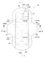
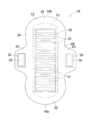
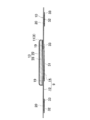
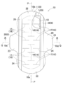
図1~3を参照すると、本発明の吸収性物品の一例として示す生理用ナプキン10は、その幅方向における寸法を2等分する縦軸P及びその長さ寸法における寸法を2等分する横軸Qと、肌対向面側及びその反対側の非肌対向面側と、凸曲状の第1及び第2端縁10a,10bと、横軸Qの位置する中央部において凸曲する両側縁10c,10dとを有し、肌対向面側に位置する透液性の表面シート11と、非肌対向面側に位置する伸縮性かつ不透液性の裏面シート12と、これら両シート11,12間に位置する吸液性の吸液層13と、吸液層13の底面を覆う防漏シート14とを含む。生理用ナプキン10の柔軟性を向上させるために、表面シート11と吸液層13との間に比較的に嵩高の繊維不織布製の中間シートを配置してもよい。
本発明においては、吸液層13の存在領域において、肌対向面側に位置する単数又は複数のシート部材から構成される層を表面層8、吸液構造体13の非肌対向面側に位置する単数又は複数のシート部材から構成される層を裏面層9という。したがって、吸液層13は、表面層8と裏面層9との間に配置される。本実施形態においては、表面層8は、表面シート11、中間シート(図示せず)から構成され、裏面層9は、裏面シート12、防漏シート14から構成される。また、本実施形態において、後記の一対のサイドシート20は、裏面シート12と別体のシート部材から形成されているが、サイドシート20を配置せず、裏面シート12を生理用ナプキン10全体の大きさを有するシート材料から形成し、ウイング部を裏面シート12から形成してもよい。なお、本明細書における伸長率100%とは、伸長力が作用される前の自然状態の長さから2倍の長さになることを意味し、伸長率50%は、伸長力が作用される前の自然状態の長さから1.5倍の長さになることを意味するものである。また、生理用ナプキン10を縦軸Pの方向へ引っ張るとは、生理用ナプキン10の一方端部と他方端部とを掴んで、縦軸Pの方向において、それらを互いに離間させるように逆方向に引っ張ることのほかに、一方端部を固定し、他方端部を一方端部と離間するように縦軸Pの方向の外側へ引っ張ることを意味する。
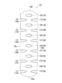
吸液層13は、その全域に配置された、少なくとも縦軸Pの方向におけるその長さ寸法を伸長可能とする伸長手段を有する。伸長手段は、その中央部において縦軸Pの方向へ並んで配置された横軸Qの方向へ延びる複数の第1スリット15から構成された中央伸長手段16と、横軸Qの方向へ延びる、両側部において縦軸Pの方向へ所与寸法離間した状態で並んで配置された複数の第2スリット17から構成されたサイド伸長手段18とを有する。本実施形態における吸液層13の第1及び第2スリット15,17は、吸液層13を貫通するもののほかに、表面側又は裏面側に吸液層13の一部が残っているものであって吸液層13を少なくとも縦軸Pの方向において伸長可能とする溝を含む。
表面シート11は、両側部(折曲部位)19が内方へ折り曲げられて防漏シート14のうちの裏面シート12と対向する面に接合される。裏面シート12は、表面シート11よりもさらに横軸Qの方向の外側へ延出しており、その表面側において一対のサイドシート20が固定されている。表面シート11、裏面シート12及びサイドシート20の一部によって吸液層13より縦軸Pの方向の外側に位置するエンドフラップ22が形成され、裏面シート12とサイドシート20によって、吸液層13より横軸Qの方向の外側に位置し、横軸Q近傍において外方へ凸曲する一対のウイング部23を有するサイドフラップ24が形成される。吸液層13の底面に防漏シート14が配置されていることによって体液の漏れを防止することができる。
表面層8と裏面層9とは、単数又は複数のシート部材から構成(表面層8は、表面シート11と中間シート、裏面層9は、裏面シート12と防漏シート14)されて、少なくとも縦軸Pの方向へ伸長性を有している。すなわち、表裏面層8,9を構成するすべてのシートが弾性的又は非弾性的な伸長性を有する。非弾性かつ伸長性を有するシートとしては、例えば、スパンボンド繊維不織布もしくは、SMS(スパンボンド・メルトブロー・スパンボンド)や繊維不織布等の各種公知の繊維不織布やプラスチックフィルムにギア延伸加工やスリット加工を施すことによって、縦軸Pの方向への所定の伸長性を付与したものを用いることができる。
また、表裏面層8、9を構成する弾性かつ伸長性を有するシート(すなわち、伸縮性シート)として、質量が10~40g/m2、より好ましくは、質量15~30g/m2の弾性繊維(弾性フィラメント)から構成されたスパンボンド不織布、エアースルー不織布、ニードルパンチ不織布等各種公知の製法によって製造された伸縮性の繊維不織布を用いることができる。弾性繊維は、熱可塑性エラストマーやゴムなどを原料とするものであって、特に熱可塑性エラストマーを原料として用いる場合には、通常の熱可塑性樹脂と同様に押出機を用いた溶融紡糸が可能であり、またそのようにして得られた繊維は熱融着させ易く、伸縮性の繊維不織布として好適である。熱可塑性エラストマーとしては、SBS(スチレン-ブタジエン-スチレン)、SIS(スチレン-イソプレン-スチレン)、SEBS(スチレン-エチレン-ブタジエン-スチレン)、SEPS(スチレン-エチレン-プロピレン-スチレン)等のスチレン系エラストマー、オレフィン系エラストマー、ポリエステル系エラストマー、ポリウレタン系エラストマーを挙げることができる。これらは、一種を単独で又は二種以上を組み合わせて用いることができる。また、これらの樹脂からなる芯鞘型又はサイド・バイ・サイド型の複合繊維を用いることもできる。
ここで、本発明における、「伸長性を有するシート」とは、自然状態から縦軸Pの方向へ30mN/25mmの力で対象のシートを伸長した場合において、自然状態における縦軸Pの方向における寸法から3%以上伸長可能であるもの、すなわち、伸長力を作用させる前の長さから1.03倍以上の長さになることが可能になるものである。
<伸長性を有するシートの伸長率の測定>
伸長性を有するシートの伸長率の測定には、インストロン型万能引張試験機(島津製作所製、オートグラフAG-1)を用いた。具体的な測定方法としては、伸長性を有するシートから縦軸Pの方向と横軸Qの方向とにおける寸法が50mm×25mmの大きさであるサンプルを切り出して、サンプルの両端をチャックで把持するようにセットして、縦軸Pの方向における長さ30mmを100mm/minの速度で引張、横軸Qの方向の寸法25mm幅当たりについて30mNの伸長力が縦軸Qの方向に作用したときの伸び率(%)を測定した。
伸長性を有するシートの伸長率の測定には、インストロン型万能引張試験機(島津製作所製、オートグラフAG-1)を用いた。具体的な測定方法としては、伸長性を有するシートから縦軸Pの方向と横軸Qの方向とにおける寸法が50mm×25mmの大きさであるサンプルを切り出して、サンプルの両端をチャックで把持するようにセットして、縦軸Pの方向における長さ30mmを100mm/minの速度で引張、横軸Qの方向の寸法25mm幅当たりについて30mNの伸長力が縦軸Qの方向に作用したときの伸び率(%)を測定した。
また、表裏面層8,9を構成するシート部材のうちの少なくとも1つのシート部材は、縦軸Pの方向へ伸縮性を有するものである。かかる伸縮性を有するシートは、既述の弾性伸縮性不織布のほかに、弾性繊維のみから構成されたスパンボンド不織布もしくは、SMS(スパンボンド・メルトブロー・スパンボンド)やSM(スパンボンド・メルトブロー)の複数層等を用いることができ、また、かかる伸縮性の繊維不織布を非伸縮性繊維から構成された非伸縮性の繊維不織布と接合してなる伸縮性複合シートから形成することもできる。伸縮性複合シートは、2枚の非伸縮性の繊維不織布の間に伸縮性の繊維不織布が配置された複数層から形成することもできる。非伸縮性の繊維不織布は、スパンボンド繊維不織布のほかに、エアースルー繊維不織布、ヒートロール繊維不織布等の各種公知の繊維不織布から形成される。非弾性シートとして用いる不織布の構成繊維としては、ポリエチレン(PE)、ポリプロピレン(PP)、ポリエステル(PET)等からなる繊維等が挙げられる。
各シート11,12,14として、伸縮性の繊維不織布と非伸縮性の繊維不織布との伸縮性複合シートを用いる場合には、非伸縮性の繊維不織布を所定の倍率に伸長された伸縮性の繊維不織布にエンボス/デボス加工またはホットメルト接着剤等の公知の接合手段を介して接合したり、また、両繊維不織布を接合した後に、少なくとも非伸縮性の繊維不織布を部分切断することによって複合シート全体に伸縮性を付与してもよい。かかる部分切断は、伸縮性複合シートの幅方向全体に一連に延びるものではなく、ドット状やスリット状に離散的に配置されたものであって、主として非伸縮性の繊維不織布が切断され、伸縮性の繊維不織布はその伸縮性が低下しないように切断されていないことが好ましい。
ここで、本発明における伸縮性を有するシートは、自然状態における縦軸Pの寸法から60%以下、好ましくは、40%以下に伸長された状態(1.4~1.6倍に伸長された状態)で他のシート部材に固定される。このように、伸縮性を有するシートは、比較的に低い伸長率で固定されており、かつ、生理用ナプキン10の吸液層13が所要の剛性を有することから、伸縮性を有するシートが収縮せずに、伸長された状態を維持する。したがって、生理用ナプキン10は、自然状態においてフラットな形態をなし、かつ、それに対して縦軸Pの方向において引っ張る力が加えられたときに、伸長状態からさらに伸長されるので、生理用ナプキンはフラットな形態を維持することができる。したがって、着衣に止着した状態でそれとともに伸長されたときでも、身体の形状に沿うような湾曲状を呈することができる。
かかる伸縮性を有するシートが所定の伸長率で固定されていることを以下の方法で確認することができた。まず、裏面シート(プラスチックフィルム)12が接合されるコアラップシート29又はサイドシート20が非弾性かつ伸長性を有するシートから形成され、裏面シート12が伸縮性を有するシートから形成されている場合において、両シートがホットメルト接着剤を介して接合された部分の一部を生理用ナプキン10から切り出してサンプルとした。次に、サンプルの接合界面にコールドスプレーを吹き付けて非弾性かつ伸長性を有するシートのシート片と伸縮性を有するシートのシート片とを剥離して、自然状態とした。自然状態における両シート片の長さ寸法を測定して、非弾性かつ伸長性を有するシート片の長さ寸法(mm)÷伸縮性を有するシートのシート片の長さ寸法(mm)を算出し、算出された値が1.6以下であった。したがって、伸縮性を有するシートである裏面シート12は、伸長率が60%以下の状態で固定されていたことが確認できた。
表面シート11は、体液を透過して吸液層13に吸収、保持させるべく、透液性を有するものであって、前記の構成繊維または繊維不織布を親水処理したもの、または、構成繊維として親水性繊維を用いた繊維不織布を用いることができる。また、親水処理をせずに、多孔性の繊維不織布を用いることによって、所要の透液性を有するものであってよい。防漏シート14は、疎水性を有し、熱可塑性ポリウレタンポリマー等を主とした(弾性)熱可塑性フィルムから形成される。防漏シート14は、かかる熱可塑性フィルムと伸縮性の繊維不織布との複合シートから形成することもできる。
吸液層13は、所定の形状、大きさに賦形されたパネル形状であって、シート部材に比して剛性の高い半剛性かつ弾性復元性を有する吸液性コア28と、オプションとして、保形性及び液拡散性の向上のために吸液性コア28を包被する透液性かつ伸長性のコアラップシート29とを有する。コアラップシート29には、他の伸長性を有するシートと同様に、公知の繊維不織布にギア延伸加工やスリット加工を施したもの、弾性繊維不織布、又は、弾性繊維を含みかつギア延伸加工を施した弾性伸縮シートが好適に用いられる。吸液性コア28は、エアレイド繊維不織布、フラッフ木材パルプ及び高吸収性ポリマー粒子(SAP)を混合したものから形成される。フラッフ木材パルプは、それとともに、またはその代わりとして、例えば、化学パルプ、セルロース繊維、レーヨン、アセテートなどの人工セルロース繊維を用いることができる。エアレイド不織布は、例えば、パルプと合成繊維とを熱融着させまたはバインダーで結合させたものを用いることができる。高吸収性ポリマー粒子は、水溶性高分子が適度に架橋した三次元網目構造を有するものであって、自重の30~60倍の水を吸収するが本質的に水不溶性であり、例えば、デンプン系、アクリル酸系、アミノ酸系の粒子状または繊維状のポリマーを用いることができる。
本実施形態に係る吸液層13としては、高吸収性ポリマー粒子を含まない、エアレイド繊維不織布を単層又は複数層に重ねて形成されたものを使用することが好ましい。高吸収性ポリマー粒子を含まないことによって、その製造工程において第1及び第2スリット15,17を形成し易く、それらスリット15,17から微細な粒子状の高吸収性ポリマー粒子が漏れ出ることはないからである。また、第1及び第2スリット15,17が形成されていることによって縦軸Pの方向における体液の拡散がし難くなっているところ、高吸収性ポリマー粒子はフラッフ木材パルプ等の吸収材料に比して吸収速度が遅いため、高吸収性ポリマー粒子が含有されていないことによって縦軸Pの方向への拡散、吸収速度がさらに低下するのを防止することができる。
図2を参照すると、生理用ナプキン10の裏面側、すなわち、裏面シート12の外面には、下着等の着衣に生理用ナプキン10を取り付けるための、感圧性接着剤から形成された、その中央部において横軸Qの方向へライン状に延び、縦軸Pの方向へ所定寸法離間して並ぶ複数の第1止着部31が配置される。また、ウイング部23の外面にも、感圧性接着剤から形成された第2止着部32が配置される。第1及び第2止着部31,32は、プラスチックフィルム製又は繊維不織布製のセパレータ33で被覆される。第1及び第2止着部31,32は、実用レベルにおいて十分な着用者の着衣に対する止着強度を有するものであること好ましく、具体的には、約2.0~4.0Nの止着強度を有する。第1及び第2止着部31,32は、第1及び第2スリット15,17とおむつ10の平面視において互いに重なっておらず、少なくとも、吸液層13の存在領域を縦軸Pの方向において三等分したときに、第1端縁10a側の領域と第2端縁10b側の領域とにおいて、平面視において互いに重なっていないことが好ましい。このように、第1及び第2止着部31,32が第1及び第2スリット15,17と平面視において互いに重なっていないことから、伸長時における各スリット15,17の開口が抑制されず、吸液層13は所要の伸長性を発揮しうる。第1及び第2止着部31,32がかかる配置態様を有することによって、生理用ナプキン10の両端側において所要の伸長性を確保することができ、それらの伸長性が抑制される場合に比して、着用感が良好となる。
図示していないが、第1及び第2端縁10a,10bと両側縁10c,10dとから画成される生理用ナプキン10の外周縁では、各シート部材が、公知の接合手段、例えば、熱エンボス加工、ソニック加工等の各種熱溶着手段によって接合されたシール部(ラウンドシール)が形成される。また、シール部によって接合されている該外周縁を除いて、互いに重なり合うシート部材どうしは、この種の分野において公知のホットメルト接着剤を用いることができるが、生理用ナプキン10全体の伸縮性を阻害しないために、公知のゴム系接着剤等及びそれらの混合物を材料とするホットメルト接着剤を用いることが好ましい。
吸液層13に第1及び第2スリット15,17を形成する方法としては、公知の切断手段を採用することができるが、吸液層13が高吸収性ポリマー粒子を含む場合には熱可塑性繊維等の熱融着材料を混在させ、吸液性コア28のみ又はそれをコアラップシート29で包被した状態において切断手段で部分的に切断するときに、切断と同時又は切断の前後において熱融着性材料(コアラップシート29が熱可塑性繊維から形成される場合には、コアラップシート29も同時に融着される)を融着させ、該熱融着性材料によって切断面から高吸収性ポリマー粒子が漏れ出るのを防止することができる。
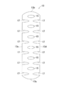
図4及び5を参照すると、吸液層13は、縦軸Pの方向において互いに対向する前後端縁13a,13bと、横軸Qの方向において互いに対向する両側縁13c,13dとを有する。中央伸長手段16は、吸液層13の中央部において縦軸Pと交差して、縦軸Pの方向において所与寸法離間して配置された複数の第1スリット15から構成される。一方、サイド伸長手段18は、第1スリット15間において、両側縁10c,10dから縦軸Pに向かってへ延び、かつ、縦軸P近傍において横軸Qの方向において互いに離間する複数の複数の一対の第2スリット17から構成される。第1スリット15と第2スリット17とは、その一部が縦軸Pの方向において互いに交差している。ここで、「互いに交差する」とは、両側縁13c,13dから縦軸Pに向かって延びる第2スリット17の内端が第1スリット15の外端よりも縦軸P側に位置し、それらの一部が互いに縦軸Pの方向において対向して位置することを意味する。吸液層13は、中央伸長手段16及びサイド伸長手段18を有することによって、他のシート部材とともに生理用ナプキン10全体が縦軸Pの方向において伸長されたときに、第1スリット15によって吸液層13の中央部には複数の円形の開口が形成され、両側縁13c,13dから内方へ延びる第2スリット17によってその開口の間の部分も縦軸Pの方向へ伸長されるので、全体が縦軸Pの方向へ伸長される。
表裏面層8,9を構成するシート部材の少なくとも1つのシート部材が伸縮性を有することによって、生理用ナプキン10は伸長された後に収縮する性能を有する。具体的には、例えば、裏面層9を構成する裏面シート12、防漏シート14及びサイドシート20のうちの少なくとも1つのシート部材が伸縮性を有するものであれば、生理用ナプキン10全体が縦軸Pの方向へ伸長されたときに、伸縮可能である。本実施形態における技術的効果を奏するためには、生理用ナプキン10自体が、自然状態から前記縦軸の方向において約700mN/25mmの力で引っ張ったときに、少なくとも前記縦軸の方向へ3%以上伸長可能、すなわち、伸長力が付与される前の長さから1.03倍以上の長さになることが好ましい。かかる場合には、生理用ナプキン10を縦軸Pの方向へ伸長したときに、表裏面層8,9とともに吸液層13が各伸長手段16,18によって伸長されて、生理用ナプキン10は、着衣とともに身体形状に沿った形態をなすことができる。また、生理用ナプキン10は、伸縮性を有するシートがそれが固定された所定の伸長率に応じて収縮するので、着用中における身体の動きにも順応することができる。
<生理用ナプキンの伸長率の測定方法>
生理用ナプキン10の両端を引張試験機(例えば、インストロンタイプの引張試験機)のチャックによって10~20mmの幅だけ把持して幅25mm当たりについて、100mm/minの速度で引っ張り、チャック間において生理用ナプキンが損傷されることのない、700mNの伸長力が縦軸Pの方向に作用したときの伸長率(%)を測定した。なお、図示していないが、生理用ナプキン10が起立性を有する立体カフを備える場合には、立体カフを取り除いた状態で測定をする。
生理用ナプキン10の両端を引張試験機(例えば、インストロンタイプの引張試験機)のチャックによって10~20mmの幅だけ把持して幅25mm当たりについて、100mm/minの速度で引っ張り、チャック間において生理用ナプキンが損傷されることのない、700mNの伸長力が縦軸Pの方向に作用したときの伸長率(%)を測定した。なお、図示していないが、生理用ナプキン10が起立性を有する立体カフを備える場合には、立体カフを取り除いた状態で測定をする。
吸液層13の縦軸Pの方向における伸長率は、第1及び第2スリット15,17の形状、大きさ、離間寸法等に依存するところ、吸液層13が縦軸Pの方向において約150~200%の伸長倍率を有するためには、吸液層13の横軸Qの方向の寸法W1が約50~120mm、縦軸Pの方向の寸法L1が約150~470mmの場合において、第1及び第2スリット15,17の長さ寸法(横軸Qの方向における寸法)W2が好ましくは約30~70mm、さらに好ましくは約40~60mm、縦軸Pの方向において隣接する第1スリット15と第2スリット17との縦軸Pの方向における離間寸法R1が、好ましくは約5~30mm、さらに好ましくは、約8~15mm、横軸Qの方向に並ぶ一対の第2スリット17間の離間寸法R2は、好ましくは約5~30mm、さらに好ましくは約10~20mmである。
第1及び第2スリット15,17の長さ寸法W2が約30mm以下の場合には、吸液層13が縦軸Pの方向に十分に伸長されず、生理用ナプキン10全体の伸長性が低下するおそれがある。一方、寸法W2が約70mm以上の場合には、吸液層13の引張強度が低下し、着用操作中又は着用中にその形状が崩れるおそれがある。また、離間寸法R1,R2がそれぞれ約5mm以下の場合には、吸液層13の伸長性は向上する一方、第1スリット15と第2スリット17との離間寸法R1、第2スリット17どうしの離間寸法R2が小さくなり、吸液層13の引張強度が低下して、着用中又は着用操作中にその一部が破断したりするおそれがある。一方、離間寸法R1,R2がそれぞれ約30mm以上の場合には、吸液層13が所要の引張強度を有するものの、伸長性が低下し、生理用ナプキン10全体が着衣に取り付け状態で十分に伸長することができなくなるおそれがある。
図6を参照すると、生理用ナプキン10の着用状態において、生理用ナプキン10は着衣の内面に取り付けられ、生理用ナプキン10を構成する各シート部材及びその吸液層13が着衣とともに着用者の身体39に沿って湾曲状に伸長されるので、着衣及び着用者の身体39に対する密着性が向上し、かつ、着用者の身体39の動きに順応し易く、防漏性及び装着性に優れる。中央伸長手段16及びサイド伸長手段18を構成する第1及び第2スリット15,17が、吸液層13全体の規則的な位置に設けられていることによって、伸長されたときに第1及び第2スリット15,17による開口が規則的な形状、大きさで形成されるので、スリットが不規則な大きさ、位置に形成される場合に比して、吸液層13が伸長された状態から収縮して元の状態に戻り易く、復元性に優れている。また、第2スリット17が両側縁10c,10dから内方へ延びていることによって、それが両側縁10c,10dよりも内側の位置から内方へ延びている場合に比して吸液層13全体が縦軸Pの方向へ伸長され易くなっている。
また、例えば、吸液層15の伸長手段が、両側縁10c,10dから内方へ延びるスリットのみから形成されている場合には、吸液層15に排泄された体液がそのスリットに沿って横軸Qの方向へ移動して吸液層15の外部に漏れ出るおそれがあるところ、本実施形態においては、吸液層13の中央部において縦軸Pの方向へ所与寸法離間して並ぶ第1スリット15間に両側縁10c,10dから内方へ延びる第2スリット17が位置することから、中央部の第1スリット15間に排泄された体液40が中央部から横軸Qの方向の外側へ移動して外部に漏れ難くなる。また、縦軸Pの方向において第1及び第2スリット15,17の一部が交差していることによってさらに縦軸Pの方向へ伸長され易く、1つの開口が比較的に小さい場合であっても所要の伸長率を発揮することができる。すなわち、本実施形態の第1及び第2スリット15,17の配置パターンによれば、所要の伸長性及び体液吸収保持性を両立することができる。また、表裏面層8,9の少なくとも一方において、構成するシート部材の少なくとも1つが伸縮性を有することによって、生理用ナプキン10全体としても僅かに収縮可能であって、着用中における身体の動きに順応することができる。
また、他の実施例として、表裏面層8,9を構成するすべてのシート部材、すなわち、表面シート11、裏面シート12、防漏シート14、サイドシート20を、例えば、弾性伸縮性繊維不織布等の伸縮性を有するシートから形成することもできる。かかる場合には、例えば、吸液層13の密度が約0.06~0.1g/cm3であって、吸液層13は伸長率が約100~200%であることが好ましい。通常、布製の下着等の着衣は、着用者の身体に対するフィット性等を発揮するために、股下部分において着用者の会陰部に沿って湾曲状を呈するように、その長手方向へ少なくとも約50%伸長(伸長力がかかる前の寸法から)するように設計されて製造されている。生理用ナプキン10を着衣に取り付けてそれとともに約50%伸長させるためには、生理用ナプキン10を構成する各シート部材及び吸液層13が互いに外周縁に位置するシール部やホットメルト接着剤等によって互いに接合され、シート材料及び吸液層13の材料自体の伸長率が低下されることを考慮すれば、着衣の約50%の伸長倍率に対し、生理用ナプキン10を構成する部材のうちで、最も伸長/収縮後の形状維持が難しい吸液層13が、100%以上に伸長できるようにすることで、伸長/収縮を繰り返してもその形状が維持され易くなるといえる。
<吸液層の伸長率の測定方法>
吸液層13の伸長率の測定方法としては、まず、吸液層13の接合界面にコールドスプレーを吹き付けて、生理用ナプキン10から吸液層13を取り出してサンプルとする。サンプルの一端を引張試験機(例えば、インストロンタイプの引張試験機)を一方のチャックに挟持させ、他方端を他方のチャックに挟持させて、引っ張り速度50mm/分で吸液層13の吸液コア28が目視において破断されるまで引っ張る。吸液性コア28の破断時の吸液層13の縦軸Pの方向における長さ寸法÷生理用ナプキン10から取り出した時(初期)の縦軸Pの方向における長さ寸法を算出し、例えば、算出された値が2.5であった場合には、伸長率は、150%とする。
吸液層13の伸長率の測定方法としては、まず、吸液層13の接合界面にコールドスプレーを吹き付けて、生理用ナプキン10から吸液層13を取り出してサンプルとする。サンプルの一端を引張試験機(例えば、インストロンタイプの引張試験機)を一方のチャックに挟持させ、他方端を他方のチャックに挟持させて、引っ張り速度50mm/分で吸液層13の吸液コア28が目視において破断されるまで引っ張る。吸液性コア28の破断時の吸液層13の縦軸Pの方向における長さ寸法÷生理用ナプキン10から取り出した時(初期)の縦軸Pの方向における長さ寸法を算出し、例えば、算出された値が2.5であった場合には、伸長率は、150%とする。
このように、表面シート11が透液性を有する伸縮性の繊維不織布から形成されている場合には、肌触りが良好であり、着用者の肌に触れる全てのシート部材、すなわち、表面層8を構成する表面シート11、裏面シート12、サイドシート20がいずれも伸縮性の繊維不織布から形成されることによって、生理用ナプキン全体として下着のような肌触りと柔軟性を有し、着用感が向上する。また、伸縮性を有する表裏面シート11,12と、伸縮性を有するサイドシート20とによってサイドフラップ24とが形成されるので、サイドフラップ24が表裏面シート11、12のみから形成される場合に比してサイドフラップ24の強度が向上するとともに伸縮性が向上し、サイドフラップ24を横軸Qの方向へ引っ張りながらウイング部23の裏面側に位置する第2止着部32を介して着衣に止着するときに、安定的に止着される。
<変更例1>
図7及び8を参照すると、吸液層13の変更例の一つにおいては、第1及び第2スリット15,17が波状であって、吸液層13が着衣とともに縦軸Pの方向へ伸長された状態において、第1及び第2スリット15,17による開口もその形状が波状を有する。第1及び第2スリットが直状の場合には、それを湾曲させて身体にフィットさせることになるので、直状から曲状に変形された部分が僅かに変形したり硬くなったりして着用者に違和感を与えるおそれがあるところ、本変更例のように、波状であって、いわば、連続する曲状のときには、スリットの形状に沿って湾曲されるので、かかる違和感を抑制することができる。
図7及び8を参照すると、吸液層13の変更例の一つにおいては、第1及び第2スリット15,17が波状であって、吸液層13が着衣とともに縦軸Pの方向へ伸長された状態において、第1及び第2スリット15,17による開口もその形状が波状を有する。第1及び第2スリットが直状の場合には、それを湾曲させて身体にフィットさせることになるので、直状から曲状に変形された部分が僅かに変形したり硬くなったりして着用者に違和感を与えるおそれがあるところ、本変更例のように、波状であって、いわば、連続する曲状のときには、スリットの形状に沿って湾曲されるので、かかる違和感を抑制することができる。
<変更例2>
図9及び図10を参照すると、本変更例においては、表面シート11とサイドシート20との間には、第1及び第2端縁10a,10b間において、折曲部位19の外側縁からウイング部23の内側縁まで延びる一対の弾性補助シート26が配置される。弾性補助シート26は、吸液層13の両側部の外側に位置してその配置領域に伸縮性を付与することによって、シート部材よりも剛性の高い半剛性の吸液層13が下着等の着衣とともに湾曲状に伸長されるのを補助する。このように、表裏面層8,9を構成するシート部材のいずれかである伸縮性を有するシートとともに、弾性補助シート26が伸縮することによって、生理用ナプキン10は、着用中により着用者の身体の動きに順応し易くなるといえる。
図9及び図10を参照すると、本変更例においては、表面シート11とサイドシート20との間には、第1及び第2端縁10a,10b間において、折曲部位19の外側縁からウイング部23の内側縁まで延びる一対の弾性補助シート26が配置される。弾性補助シート26は、吸液層13の両側部の外側に位置してその配置領域に伸縮性を付与することによって、シート部材よりも剛性の高い半剛性の吸液層13が下着等の着衣とともに湾曲状に伸長されるのを補助する。このように、表裏面層8,9を構成するシート部材のいずれかである伸縮性を有するシートとともに、弾性補助シート26が伸縮することによって、生理用ナプキン10は、着用中により着用者の身体の動きに順応し易くなるといえる。
なお、生理用ナプキン10を構成する各構成部材には、特に明記されていない限りにおいて、本明細書に記載されている材料のほかに、この種の分野において通常用いられている、各種公知の材料を制限なく用いることができる。また、本明細書及び特許請求の範囲において使用されている「第1」および「第2」の用語は、同様の要素、位置等を単に区別するために用いている。また、生理用ナプキン10の表面側から裏面側に向かって、体液の拡散性を向上させるために、所定パターンの圧縮条溝が形成されていてもよい。
以上の記載した本発明に関する開示は、少なくとも下記事項に要約することができる。
縦軸及び横軸と、肌対向面及びその反対側の非肌対向面とを有し、前記肌対向面側に位置する表面層と、前記非肌対向面側に位置する裏面層と、前記表裏面層間に介在された吸液層とを含む吸収性物品において、前記表面層と前記裏面層とは、単数又は複数のシート部材から構成されて、少なくとも前記縦軸の方向へ伸長性を有しており、前記表裏面層を構成する前記シート部材のうちの少なくとも1つは、前記縦軸の方向へ伸縮性を有し、前記吸液層は、その中央部に位置する中央伸長手段と、両側部に位置するサイド伸長手段とを含み、前記中央伸長手段は、前記縦軸と交差し、かつ、前記縦軸の方向において所与寸法離間して並んだ複数の第1スリットから形成され、前記サイド伸長手段は、前記吸液層の両側縁から縦軸に向かって延び、かつ、前記縦軸近傍において横軸の方向に互いに離間する複数の一対の第2スリットとから形成されており、前記縦軸の方向に並ぶ前記第1スリット間に前記第2スリットが位置し、前記第2スリットの内端が前記第1スリットの外端よりも前記縦軸側に位置し、前記吸液層が、少なくとも前記縦軸の方向へ伸長可能である。
上記段落に開示した本発明は、少なくとも下記の実施形態を含み、該実施形態を単独又は組み合せることができる。
(1)自然状態から前記縦軸の方向において約700mN/25mmの力で引っ張ったときに、少なくとも前記縦軸の方向へ3%以上伸長可能である。
(2)前記表面層は透液性の表面シートを有し、前記裏面層は、不透液性の裏面シートを有し、前記表裏面シートのうちの少なくとも一方が、伸縮性の繊維不織布から形成される。
(3)前記第1スリットと前記第2スリットとの前記縦軸の方向における離間寸法が約5.0~30.0mm、前記横軸の方向において対向する1対の前記第2スリットの離間寸法が約5.0~30.0mmである。
(4)前記裏面層は、吸液層の底面に配置された、不透液性かつ伸縮性の防漏シートを有する。
(5)前記吸液層の前記両側部から前記横軸の方向の外側へ延びる伸縮性を有するサイドシートが配置される。
(6)前記吸液層の両側縁の外側における前記表面シート、前記裏面シート及び前記サイドシートから形成されるサイドフラップには、前記縦軸の方向へ延びる一対の弾性補助シートが配置される。
10 生理用ナプキン(吸収性物品)
8 表面層
9 裏面層
11 表面シート
12 裏面シート
13 吸液層
13c,13d 吸液層の側縁
14 防漏シート
15 第1スリット
16 中央伸長手段
17 第2スリット
18 サイド伸長手段
19 表面シートの両側部(折曲部位)
20 サイドシート
24 サイドフラップ
26 弾性補助シート
P 縦軸
Q 横軸
R1 第1スリットと第2スリットとの縦軸の方向における離間寸法
R2 横軸の方向において離間対向する第2スリットどうしの離間寸法
8 表面層
9 裏面層
11 表面シート
12 裏面シート
13 吸液層
13c,13d 吸液層の側縁
14 防漏シート
15 第1スリット
16 中央伸長手段
17 第2スリット
18 サイド伸長手段
19 表面シートの両側部(折曲部位)
20 サイドシート
24 サイドフラップ
26 弾性補助シート
P 縦軸
Q 横軸
R1 第1スリットと第2スリットとの縦軸の方向における離間寸法
R2 横軸の方向において離間対向する第2スリットどうしの離間寸法
Claims (7)
- 縦軸及び横軸と、肌対向面及びその反対側の非肌対向面とを有し、前記肌対向面側に位置する表面層と、前記非肌対向面側に位置する裏面層と、前記表裏面層間に介在された吸液層とを含む吸収性物品において、
前記表面層と前記裏面層とは、単数又は複数のシート部材から構成されて、少なくとも前記縦軸の方向へ伸長性を有しており、
前記表裏面層を構成する前記シート部材のうちの少なくとも1つは、前記縦軸の方向へ伸縮性を有し、
前記吸液層は、その中央部に位置する中央伸長手段と、両側部に位置するサイド伸長手段とを含み、
前記中央伸長手段は、前記縦軸と交差し、かつ、前記縦軸の方向において所与寸法離間して並んだ複数の第1スリットから形成され、
前記サイド伸長手段は、前記吸液層の両側縁から縦軸に向かって延び、かつ、前記縦軸近傍において横軸の方向に互いに離間する複数の一対の第2スリットとから形成されており、
前記縦軸の方向に並ぶ前記第1スリット間に前記第2スリットが位置し、前記第2スリットの内端が前記第1スリットの外端よりも前記縦軸側に位置し、前記吸液層が、少なくとも前記縦軸の方向へ伸長可能であることを特徴とする前記吸収性物品。 - 自然状態から前記縦軸の方向において約700mN/25mmの力で引っ張ったときに、少なくとも前記縦軸の方向へ3%以上伸長可能である請求項1に記載の吸収性物品。
- 前記表面層は透液性の表面シートを有し、前記裏面層は、不透液性の裏面シートを有し、前記表裏面シートのうちの少なくとも一方が、伸縮性の繊維不織布から形成される請求項1又は2に記載の吸収性物品。
- 前記第1スリットと前記第2スリットとの前記縦軸の方向における離間寸法が5.0~30.0mm、前記横軸の方向において対向する1対の前記第2スリットの離間寸法が5.0~30.0mmである請求項1~3のいずれかに記載の吸収性物品。
- 前記裏面層は、前記吸液層の底面に配置された、不透液性かつ伸縮性の防漏シートを有する請求項1~4のいずれかに記載の吸収性物品。
- 前記吸液層の前記両側部から前記横軸の方向の外側へ延びる伸縮性を有するサイドシートが配置される請求項1~5のいずれかに記載の吸収性物品。
- 前記吸液層の前記両側縁の外側における前記表面シート、前記裏面シート及び前記サイドシートから形成されるサイドフラップには、前記縦軸の方向へ延びる一対の弾性補助シートが配置される請求項6に記載の吸収性物品。
Applications Claiming Priority (2)
| Application Number | Priority Date | Filing Date | Title |
|---|---|---|---|
| JP2014-135427 | 2014-06-30 | ||
| JP2014135427A JP6207475B2 (ja) | 2014-06-30 | 2014-06-30 | 吸収性物品 |
Publications (1)
| Publication Number | Publication Date |
|---|---|
| WO2016002314A1 true WO2016002314A1 (ja) | 2016-01-07 |
Family
ID=55018872
Family Applications (1)
| Application Number | Title | Priority Date | Filing Date |
|---|---|---|---|
| PCT/JP2015/061942 Ceased WO2016002314A1 (ja) | 2014-06-30 | 2015-04-20 | 吸収性物品 |
Country Status (3)
| Country | Link |
|---|---|
| JP (1) | JP6207475B2 (ja) |
| TW (1) | TWI667017B (ja) |
| WO (1) | WO2016002314A1 (ja) |
Cited By (3)
| Publication number | Priority date | Publication date | Assignee | Title |
|---|---|---|---|---|
| JP2017176743A (ja) * | 2016-03-31 | 2017-10-05 | ユニ・チャーム株式会社 | 吸収性物品 |
| CN109069325A (zh) * | 2016-04-28 | 2018-12-21 | 尤妮佳股份有限公司 | 吸收性物品 |
| JP2019018033A (ja) * | 2018-10-03 | 2019-02-07 | ユニ・チャーム株式会社 | 吸収性物品 |
Families Citing this family (3)
| Publication number | Priority date | Publication date | Assignee | Title |
|---|---|---|---|---|
| CN109568016A (zh) * | 2018-11-09 | 2019-04-05 | 洪雅县瓦屋山药业有限公司 | 一种利用雅连制作的消炎抑菌卫生巾 |
| JP7534876B2 (ja) * | 2020-06-30 | 2024-08-15 | 日本製紙クレシア株式会社 | 吸収性物品 |
| JP7488137B2 (ja) * | 2020-07-06 | 2024-05-21 | 花王株式会社 | 吸収性シート及び吸収性物品 |
Citations (4)
| Publication number | Priority date | Publication date | Assignee | Title |
|---|---|---|---|---|
| JPH0187720U (ja) * | 1987-12-01 | 1989-06-09 | ||
| JPH06503249A (ja) * | 1990-12-19 | 1994-04-14 | ザ、プロクター、エンド、ギャンブル、カンパニー | 横方向にセグメント分けされたコアを持つ衛生ナプキン |
| JPH11508470A (ja) * | 1995-07-03 | 1999-07-27 | ザ、プロクター、エンド、ギャンブル、カンパニー | 伸長性のある関節式連結部分を備えた吸収体 |
| JP2009153736A (ja) * | 2007-12-27 | 2009-07-16 | Kao Corp | 吸収性物品 |
Family Cites Families (3)
| Publication number | Priority date | Publication date | Assignee | Title |
|---|---|---|---|---|
| JP3725008B2 (ja) * | 2000-06-21 | 2005-12-07 | 花王株式会社 | 吸収性物品 |
| JP4455241B2 (ja) * | 2004-09-14 | 2010-04-21 | ユニ・チャーム株式会社 | 生理用ナプキン |
| JP2014064858A (ja) * | 2012-09-27 | 2014-04-17 | Kao Corp | 吸収性物品 |
-
2014
- 2014-06-30 JP JP2014135427A patent/JP6207475B2/ja active Active
-
2015
- 2015-04-20 WO PCT/JP2015/061942 patent/WO2016002314A1/ja not_active Ceased
- 2015-06-25 TW TW104120539A patent/TWI667017B/zh not_active IP Right Cessation
Patent Citations (4)
| Publication number | Priority date | Publication date | Assignee | Title |
|---|---|---|---|---|
| JPH0187720U (ja) * | 1987-12-01 | 1989-06-09 | ||
| JPH06503249A (ja) * | 1990-12-19 | 1994-04-14 | ザ、プロクター、エンド、ギャンブル、カンパニー | 横方向にセグメント分けされたコアを持つ衛生ナプキン |
| JPH11508470A (ja) * | 1995-07-03 | 1999-07-27 | ザ、プロクター、エンド、ギャンブル、カンパニー | 伸長性のある関節式連結部分を備えた吸収体 |
| JP2009153736A (ja) * | 2007-12-27 | 2009-07-16 | Kao Corp | 吸収性物品 |
Cited By (4)
| Publication number | Priority date | Publication date | Assignee | Title |
|---|---|---|---|---|
| JP2017176743A (ja) * | 2016-03-31 | 2017-10-05 | ユニ・チャーム株式会社 | 吸収性物品 |
| CN109069325A (zh) * | 2016-04-28 | 2018-12-21 | 尤妮佳股份有限公司 | 吸收性物品 |
| CN109069325B (zh) * | 2016-04-28 | 2020-01-17 | 尤妮佳股份有限公司 | 吸收性物品 |
| JP2019018033A (ja) * | 2018-10-03 | 2019-02-07 | ユニ・チャーム株式会社 | 吸収性物品 |
Also Published As
| Publication number | Publication date |
|---|---|
| TWI667017B (zh) | 2019-08-01 |
| TW201620470A (zh) | 2016-06-16 |
| JP2016013200A (ja) | 2016-01-28 |
| JP6207475B2 (ja) | 2017-10-04 |
Similar Documents
| Publication | Publication Date | Title |
|---|---|---|
| KR101659902B1 (ko) | 흡수성 물품 | |
| WO2008069279A1 (ja) | 吸収性物品 | |
| JP2009160242A (ja) | 吸収体及び使い捨て吸収性物品 | |
| JP6360539B2 (ja) | 個装吸収性物品、吸収性物品、及び吸収性物品を折り畳む方法 | |
| JP6207475B2 (ja) | 吸収性物品 | |
| JP2011072720A (ja) | 吸収性物品 | |
| JP6168855B2 (ja) | 使い捨て着用物品 | |
| JP6162412B2 (ja) | 吸収性物品 | |
| JP2008161250A (ja) | 吸収性物品 | |
| JP6467213B2 (ja) | 使い捨て着用物品 | |
| WO2016002313A1 (ja) | 吸収性物品 | |
| JP6128980B2 (ja) | 使い捨てのパンツ型おむつ | |
| WO2013065620A1 (ja) | 使い捨て着用物品 | |
| JP7359553B2 (ja) | 吸収性物品、及び吸収性物品の折り畳み方法 | |
| JP6353237B2 (ja) | 吸収性物品 | |
| JP4917366B2 (ja) | 使い捨ておむつ | |
| WO2015151897A1 (ja) | 使い捨ておむつ | |
| CN107072826B (zh) | 吸收性物品 | |
| JP2017080244A (ja) | 吸収性物品 | |
| JP6636848B2 (ja) | 吸収性物品 | |
| JP5717379B2 (ja) | 吸収性物品 | |
| JP5767808B2 (ja) | パッドタイプ吸収性物品 | |
| JP5934505B2 (ja) | 吸収性物品 | |
| JP5431203B2 (ja) | 吸収性物品 | |
| JP5822903B2 (ja) | パンツ型の使い捨て着用物品 |
Legal Events
| Date | Code | Title | Description |
|---|---|---|---|
| 121 | Ep: the epo has been informed by wipo that ep was designated in this application |
Ref document number: 15815412 Country of ref document: EP Kind code of ref document: A1 |
|
| NENP | Non-entry into the national phase |
Ref country code: DE |
|
| 122 | Ep: pct application non-entry in european phase |
Ref document number: 15815412 Country of ref document: EP Kind code of ref document: A1 |