WO2016002219A1 - 洗浄装置及びロール洗浄部材 - Google Patents
洗浄装置及びロール洗浄部材 Download PDFInfo
- Publication number
- WO2016002219A1 WO2016002219A1 PCT/JP2015/003314 JP2015003314W WO2016002219A1 WO 2016002219 A1 WO2016002219 A1 WO 2016002219A1 JP 2015003314 W JP2015003314 W JP 2015003314W WO 2016002219 A1 WO2016002219 A1 WO 2016002219A1
- Authority
- WO
- WIPO (PCT)
- Prior art keywords
- substrate
- row
- protruding
- roll cleaning
- longitudinal direction
- Prior art date
- Legal status (The legal status is an assumption and is not a legal conclusion. Google has not performed a legal analysis and makes no representation as to the accuracy of the status listed.)
- Ceased
Links
Images




Classifications
-
- H—ELECTRICITY
- H10—SEMICONDUCTOR DEVICES; ELECTRIC SOLID-STATE DEVICES NOT OTHERWISE PROVIDED FOR
- H10P—GENERIC PROCESSES OR APPARATUS FOR THE MANUFACTURE OR TREATMENT OF DEVICES COVERED BY CLASS H10
- H10P72/00—Handling or holding of wafers, substrates or devices during manufacture or treatment thereof
- H10P72/04—Apparatus for manufacture or treatment
- H10P72/0402—Apparatus for fluid treatment
- H10P72/0406—Apparatus for fluid treatment for cleaning followed by drying, rinsing, stripping, blasting or the like
- H10P72/0411—Apparatus for fluid treatment for cleaning followed by drying, rinsing, stripping, blasting or the like for wet cleaning or washing
- H10P72/0412—Apparatus for fluid treatment for cleaning followed by drying, rinsing, stripping, blasting or the like for wet cleaning or washing using mainly scrubbing means, e.g. brushes
-
- A—HUMAN NECESSITIES
- A46—BRUSHWARE
- A46B—BRUSHES
- A46B13/00—Brushes with driven brush bodies or carriers
-
- A—HUMAN NECESSITIES
- A46—BRUSHWARE
- A46B—BRUSHES
- A46B13/00—Brushes with driven brush bodies or carriers
- A46B13/001—Cylindrical or annular brush bodies
-
- B—PERFORMING OPERATIONS; TRANSPORTING
- B08—CLEANING
- B08B—CLEANING IN GENERAL; PREVENTION OF FOULING IN GENERAL
- B08B1/00—Cleaning by methods involving the use of tools
- B08B1/10—Cleaning by methods involving the use of tools characterised by the type of cleaning tool
- B08B1/14—Wipes; Absorbent members, e.g. swabs or sponges
-
- B—PERFORMING OPERATIONS; TRANSPORTING
- B08—CLEANING
- B08B—CLEANING IN GENERAL; PREVENTION OF FOULING IN GENERAL
- B08B1/00—Cleaning by methods involving the use of tools
- B08B1/30—Cleaning by methods involving the use of tools by movement of cleaning members over a surface
- B08B1/32—Cleaning by methods involving the use of tools by movement of cleaning members over a surface using rotary cleaning members
- B08B1/34—Cleaning by methods involving the use of tools by movement of cleaning members over a surface using rotary cleaning members rotating about an axis parallel to the surface
-
- B—PERFORMING OPERATIONS; TRANSPORTING
- B08—CLEANING
- B08B—CLEANING IN GENERAL; PREVENTION OF FOULING IN GENERAL
- B08B11/00—Cleaning flexible or delicate articles by methods or apparatus specially adapted thereto
- B08B11/02—Devices for holding articles during cleaning
-
- B—PERFORMING OPERATIONS; TRANSPORTING
- B08—CLEANING
- B08B—CLEANING IN GENERAL; PREVENTION OF FOULING IN GENERAL
- B08B3/00—Cleaning by methods involving the use or presence of liquid or steam
- B08B3/04—Cleaning involving contact with liquid
- B08B3/08—Cleaning involving contact with liquid the liquid having chemical or dissolving effect
-
- B—PERFORMING OPERATIONS; TRANSPORTING
- B08—CLEANING
- B08B—CLEANING IN GENERAL; PREVENTION OF FOULING IN GENERAL
- B08B3/00—Cleaning by methods involving the use or presence of liquid or steam
- B08B3/04—Cleaning involving contact with liquid
- B08B3/10—Cleaning involving contact with liquid with additional treatment of the liquid or of the object being cleaned, e.g. by heat, by electricity or by vibration
-
- H—ELECTRICITY
- H10—SEMICONDUCTOR DEVICES; ELECTRIC SOLID-STATE DEVICES NOT OTHERWISE PROVIDED FOR
- H10P—GENERIC PROCESSES OR APPARATUS FOR THE MANUFACTURE OR TREATMENT OF DEVICES COVERED BY CLASS H10
- H10P52/00—Grinding, lapping or polishing of wafers, substrates or parts of devices
-
- H—ELECTRICITY
- H10—SEMICONDUCTOR DEVICES; ELECTRIC SOLID-STATE DEVICES NOT OTHERWISE PROVIDED FOR
- H10P—GENERIC PROCESSES OR APPARATUS FOR THE MANUFACTURE OR TREATMENT OF DEVICES COVERED BY CLASS H10
- H10P52/00—Grinding, lapping or polishing of wafers, substrates or parts of devices
- H10P52/40—Chemomechanical polishing [CMP]
- H10P52/402—Chemomechanical polishing [CMP] of semiconductor materials
-
- H—ELECTRICITY
- H10—SEMICONDUCTOR DEVICES; ELECTRIC SOLID-STATE DEVICES NOT OTHERWISE PROVIDED FOR
- H10P—GENERIC PROCESSES OR APPARATUS FOR THE MANUFACTURE OR TREATMENT OF DEVICES COVERED BY CLASS H10
- H10P70/00—Cleaning of wafers, substrates or parts of devices
- H10P70/20—Cleaning during device manufacture
-
- H—ELECTRICITY
- H10—SEMICONDUCTOR DEVICES; ELECTRIC SOLID-STATE DEVICES NOT OTHERWISE PROVIDED FOR
- H10P—GENERIC PROCESSES OR APPARATUS FOR THE MANUFACTURE OR TREATMENT OF DEVICES COVERED BY CLASS H10
- H10P72/00—Handling or holding of wafers, substrates or devices during manufacture or treatment thereof
- H10P72/04—Apparatus for manufacture or treatment
- H10P72/0402—Apparatus for fluid treatment
- H10P72/0406—Apparatus for fluid treatment for cleaning followed by drying, rinsing, stripping, blasting or the like
- H10P72/0411—Apparatus for fluid treatment for cleaning followed by drying, rinsing, stripping, blasting or the like for wet cleaning or washing
- H10P72/0414—Apparatus for fluid treatment for cleaning followed by drying, rinsing, stripping, blasting or the like for wet cleaning or washing using mainly spraying means, e.g. nozzles
-
- H—ELECTRICITY
- H10—SEMICONDUCTOR DEVICES; ELECTRIC SOLID-STATE DEVICES NOT OTHERWISE PROVIDED FOR
- H10P—GENERIC PROCESSES OR APPARATUS FOR THE MANUFACTURE OR TREATMENT OF DEVICES COVERED BY CLASS H10
- H10P72/00—Handling or holding of wafers, substrates or devices during manufacture or treatment thereof
- H10P72/50—Handling or holding of wafers, substrates or devices during manufacture or treatment thereof for positioning, orientation or alignment
-
- H—ELECTRICITY
- H10—SEMICONDUCTOR DEVICES; ELECTRIC SOLID-STATE DEVICES NOT OTHERWISE PROVIDED FOR
- H10P—GENERIC PROCESSES OR APPARATUS FOR THE MANUFACTURE OR TREATMENT OF DEVICES COVERED BY CLASS H10
- H10P72/00—Handling or holding of wafers, substrates or devices during manufacture or treatment thereof
- H10P72/70—Handling or holding of wafers, substrates or devices during manufacture or treatment thereof for supporting or gripping
- H10P72/76—Handling or holding of wafers, substrates or devices during manufacture or treatment thereof for supporting or gripping using mechanical means, e.g. clamps or pinches
- H10P72/7604—Handling or holding of wafers, substrates or devices during manufacture or treatment thereof for supporting or gripping using mechanical means, e.g. clamps or pinches the wafers being placed on a susceptor, stage or support
-
- H—ELECTRICITY
- H10—SEMICONDUCTOR DEVICES; ELECTRIC SOLID-STATE DEVICES NOT OTHERWISE PROVIDED FOR
- H10P—GENERIC PROCESSES OR APPARATUS FOR THE MANUFACTURE OR TREATMENT OF DEVICES COVERED BY CLASS H10
- H10P72/00—Handling or holding of wafers, substrates or devices during manufacture or treatment thereof
- H10P72/70—Handling or holding of wafers, substrates or devices during manufacture or treatment thereof for supporting or gripping
- H10P72/76—Handling or holding of wafers, substrates or devices during manufacture or treatment thereof for supporting or gripping using mechanical means, e.g. clamps or pinches
- H10P72/7604—Handling or holding of wafers, substrates or devices during manufacture or treatment thereof for supporting or gripping using mechanical means, e.g. clamps or pinches the wafers being placed on a susceptor, stage or support
- H10P72/7618—Handling or holding of wafers, substrates or devices during manufacture or treatment thereof for supporting or gripping using mechanical means, e.g. clamps or pinches the wafers being placed on a susceptor, stage or support characterised by a movable susceptor, stage or support, others than those only rotating on their own vertical axis, e.g. susceptors on a rotating carrousel
-
- H—ELECTRICITY
- H10—SEMICONDUCTOR DEVICES; ELECTRIC SOLID-STATE DEVICES NOT OTHERWISE PROVIDED FOR
- H10P—GENERIC PROCESSES OR APPARATUS FOR THE MANUFACTURE OR TREATMENT OF DEVICES COVERED BY CLASS H10
- H10P70/00—Cleaning of wafers, substrates or parts of devices
- H10P70/20—Cleaning during device manufacture
- H10P70/27—Cleaning during device manufacture during, before or after processing of conductive materials, e.g. polysilicon or amorphous silicon layers
- H10P70/277—Cleaning during device manufacture during, before or after processing of conductive materials, e.g. polysilicon or amorphous silicon layers the processing being a planarisation of conductive layers
-
- H—ELECTRICITY
- H10—SEMICONDUCTOR DEVICES; ELECTRIC SOLID-STATE DEVICES NOT OTHERWISE PROVIDED FOR
- H10P—GENERIC PROCESSES OR APPARATUS FOR THE MANUFACTURE OR TREATMENT OF DEVICES COVERED BY CLASS H10
- H10P70/00—Cleaning of wafers, substrates or parts of devices
- H10P70/60—Cleaning only by mechanical processes
Definitions
- the present technology relates to a roll cleaning member for cleaning a substrate in contact with the surface of the substrate, and a cleaning apparatus including the roll cleaning member.
- CMP substrate polishing apparatus
- roll cleaning member various types of roll cleaning members are adopted depending on the purpose of cleaning or the characteristics (size, physical properties, etc.) of the particles to be removed.
- a roll cleaning member in which a plurality of nodules (also referred to as “projection members”) are formed on the surface.
- FIG. 1 is a schematic view of a cleaning device (hereinafter referred to as “roll cleaning device”) provided with a roll cleaning member.
- the roll cleaning device 50 is rotatably supported by a plurality of (four in FIG. 1) spindles 51 that support the peripheral portion of the substrate W with the surface up and rotate the substrate W horizontally and a roll holder (not shown).
- An upper roll cleaning member (roll sponge) 52 and a lower roll cleaning member (roll sponge) 53 rotatably supported by a roll holder (not shown) are provided.
- the upper roll cleaning member 52 and the lower roll cleaning member 53 are cylindrical and are made of, for example, PVA. A plurality of nodules are formed on the surface of the upper roll cleaning member 52.
- the upper roll cleaning member 52 can be moved up and down with respect to the surface of the substrate W by the roll holder, and the lower roll cleaning member 53 can be moved up and down with respect to the back surface of the substrate W by the roll holder.
- the spindle 51 is movable in the horizontal direction.
- the upper roll cleaning member 52 is rotated as shown by an arrow F1 by a driving mechanism (not shown), and the lower roll cleaning member 53 is rotated as shown by an arrow F2 by a driving mechanism (not shown).
- Two cleaning liquid supply nozzles 54 and 55 for supplying a cleaning liquid to the surface of the substrate W are disposed above the substrate W to be supported and rotated by the spindle 51.
- the cleaning liquid supply nozzle 54 is a nozzle that supplies a rinsing liquid (for example, ultrapure water) to the surface of the substrate W
- the cleaning liquid supply nozzle 55 is a nozzle that supplies a chemical liquid to the surface of the substrate W.
- the roll cleaning device 50 rotates (spins) the top 51a by positioning the peripheral edge of the substrate W in a fitting groove formed on the outer peripheral side surface of the top 51a provided on the spindle 51 and pressing it inward. Then, the substrate W is rotated horizontally.
- two pieces 51a out of four pieces 51a give a rotational force to the substrate W, and the other two pieces 51a function as a bearing that receives the rotation of the substrate W.
- all the pieces 51a may be connected to the drive mechanism to apply a rotational force to the substrate W.
- the rinsing liquid is supplied from the cleaning liquid supply nozzle 54 to the surface of the substrate W, and the chemical liquid is supplied from the cleaning liquid supply nozzle 55 to the surface of the substrate W.
- the member 52 is lowered while being rotated and brought into contact with the surface of the rotating substrate W, whereby the surface of the substrate W is scrubbed with the upper roll cleaning member 52 in the presence of the cleaning liquid (rinsing liquid and chemical liquid).
- the length of the upper roll cleaning member 52 is set slightly longer than the diameter of the substrate W.
- the upper roll cleaning member 52 is arranged such that its central axis (rotation axis) is substantially orthogonal to the central axis (that is, the rotation center) of the substrate W and extends over the entire length of the diameter of the substrate W. As a result, the entire surface of the substrate W is simultaneously cleaned.
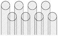
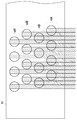
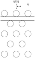
- FIG. 2 is a view showing an example of arrangement of nodules in the upper roll cleaning member 52.
- the left-right direction in FIG. 2 corresponds to the longitudinal direction (also referred to as “row direction”) of the upper roll cleaning member 52
- the up-down direction in FIG. 2 is the circumferential direction (direction perpendicular to the longitudinal direction) of the upper roll cleaning member 52. ).
- the positions of the nodules are shifted from each other in two adjacent rows.
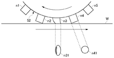
- FIG. 3 is a cross-sectional view showing a state where the nodule of the upper roll cleaning member 52 is in contact with the surface of the substrate W.
- the nodules n1 to n5 are formed in a cylindrical shape, and the tip end surface n41 is circular, but the nodule n3 that contacts the surface of the substrate W is crushed by the surface of the substrate W, and The nodule is deformed by the relative movement between the surface of the substrate W and the tip end surface n31 becomes elliptical. Further, stress concentrates on the central portion (hatched portion in FIG.
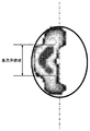
- FIG. 4 is a diagram showing the result of measuring the pressure distribution at the tip of the crushed nodule. From the measurement result of FIG. 4, it can be seen that there is a high detergency region where the detergency increases in the central portion on the upstream side of the contact surface. In the example of FIG. 4, the width of the high cleaning region in the column direction is about 44% of the width of the nodules.
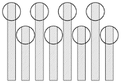
- regions to be cleaned with a high cleaning power are formed in a band shape with a space between each other. .
- regions to be cleaned with high cleaning power are formed in strips at intervals, thereby forming concentric circles on the substrate surface. Unevenness of washing can be done.
- the present technology has been made in view of the above problems, and aims to prevent or reduce cleaning unevenness in cleaning a substrate using a roll cleaning member having nodules.
- a cleaning apparatus includes a substrate support member that supports and rotates a substrate, and a roll cleaning member for scrub cleaning while rotating the surface of the substrate rotated by the substrate support member,
- the roll cleaning member includes a plurality of projecting members arranged in a longitudinal direction thereof and slidably contacting the surface of the substrate, and a locus of a high cleaning force region in a portion of the projecting member slidably contacting the substrate is a radius of the substrate. The substrate is cleaned so that there is no gap in the direction.
- the high detergency region may be set as a width of 30% to 60% of a contact region between the protruding member and the surface of the substrate.
- the high cleaning power region may be determined based on the cleaning unevenness that occurs when the actual cleaning is performed. As described above, the predetermined ratio of the contact region between the protruding member and the surface of the substrate is determined as the high cleaning power region. And the locus may exist in the radial direction of the substrate without any gap.
- the plurality of protruding members may be arranged at equal intervals in the longitudinal direction of the roll cleaning member to form a plurality of protruding member rows, and the plurality of protruding member rows adjacent in the circumferential direction of the roll cleaning member.
- the positions of the protruding members may be shifted from each other by half the pitch of the protruding members in the protruding member row.
- This configuration allows the protruding members to be arranged alternately.
- the substrate may be cleaned so that a plurality of trajectories of the high cleaning force region exist without gaps in the radial direction of the substrate.
- This configuration relatively changes the position of the roll cleaning member and the substrate, so that even if there is a gap in the locus of the high cleaning area, this gap can be reduced or eliminated.
- the peristaltic pitch sp of the roll cleaning member is sp ⁇ (np / 2) ⁇ sa, where np is the pitch of the plurality of protruding members in the protruding member row and sa is the width in the longitudinal direction of the high cleaning power region. May be satisfied.
- the roll cleaning member may include two roll cleaning members including a first roll cleaning member and a second roll cleaning member.
- the plurality of protruding members are The roll cleaning members may be arranged at equal intervals in the longitudinal direction to form a plurality of protruding member rows, and the positions of the plurality of protruding members of the protruding member rows adjacent in the circumferential direction of the roll cleaning member are The protrusion members may be displaced from each other by half the pitch of the protrusion members.
- This configuration allows the other roll cleaning member to clean the substrate so as to reduce or eliminate the cleaning unevenness caused by one roll cleaning member.
- the pitch of the protruding members in the protruding member row is np
- the plurality of the first roll cleaning members when the substrate is cleaned The position of the protruding member and the position of the plurality of protruding members of the second roll cleaning member when cleaning the substrate may be shifted by np / 4 in the column direction.
- the center of the high detergency region by the second roll cleaning member can be positioned in the center of the gap of the locus of the high detergency region by the first roll cleaning member.
- the plurality of protruding members include a plurality of protruding members arranged at a pitch np in the first row in the longitudinal direction, a plurality of protruding members arranged at a pitch np in the second row in the longitudinal direction, and the first members in the longitudinal direction.
- the longitudinal direction position and the longitudinal direction of the plurality of projecting members arranged in the second row are shifted by np / 4, and the longitudinal direction position of the plurality of projecting members arranged in the second row
- the longitudinal direction of the plurality of protruding members arranged in the third row may be shifted by np / 4, and the position in the longitudinal direction of the plurality of protruding members arranged in the third row and the fourth row May be shifted by np / 4 from the longitudinal direction of the plurality of protruding members arranged in a row.
- the high cleaning force by the second row of protruding members is provided in the center of the gap between the locus of the high cleaning force region by the first row of protruding members and the locus of the high cleaning force region by the third row of protruding members.
- the center of the locus of the force region and the locus of the high detergency region by the fourth row of protruding members can be located.
- the roll cleaning member may be slidably contacted with the substrate through the rotation center of the rotating substrate and from the rotation center to the outer periphery of the substrates on both sides, and the plurality of protruding members correspond to the rotation center. They may be arranged asymmetrically on both sides with respect to the position.
- the plurality of projecting members have a distance from a position corresponding to the rotation center of the plurality of projecting members on one side in the longitudinal direction from a position corresponding to the rotation center, and a position corresponding to the rotation center.
- the distance from the position corresponding to the rotation center of the plurality of protruding members on the other side in the longitudinal direction may be shifted by np / 4.
- the center of the locus of the high detergency region by the protruding member on the other side is located in the center of the gap between the locus of the high detergency region by the protruding member on one side of the reference position in the longitudinal direction of the roll cleaning member be able to.
- a cleaning apparatus includes a substrate support member that supports and rotates a substrate, and a roll cleaning member that performs scrub cleaning while rotating the surface of the substrate rotated by the substrate support member,
- the cleaning member includes a plurality of protruding members that are arranged at equal intervals in the longitudinal direction and are in sliding contact with the surface of the substrate, and the plurality of protruding members are arranged in the longitudinal direction of the roll cleaning member and are provided with a plurality of protruding members.
- the positions of the plurality of projecting members of the projecting member row that form a row and are adjacent to each other in the circumferential direction of the roll cleaning member are shifted from each other by half the pitch of the projecting member in the projecting member row, There is a gap between the trajectories when the high cleaning force areas of the plurality of projecting members are in sliding contact with the substrate, and are rotated by the roll cleaning member and the substrate support member during cleaning. It has a structure to relatively swing and said substrate.
- This configuration relatively changes the position of the roll cleaning member and the substrate, so that even if there is a gap in the locus of the high cleaning area, this gap can be reduced or eliminated.
- a cleaning apparatus includes a substrate support member that supports and rotates a substrate, a first roll cleaning member that performs scrub cleaning while rotating the surface of the substrate rotated by the substrate support member, And a second roll cleaning member for scrub cleaning the surface of the substrate rotated by the substrate support member, and the first roll cleaning member and the second roll cleaning member are each arranged in the longitudinal direction.
- a plurality of protruding members that are in sliding contact with the surface of the substrate, wherein in the first roll cleaning member and the second roll cleaning member, the plurality of protruding members are equally spaced in the longitudinal direction of the roll cleaning member.
- This configuration allows the other roll cleaning member to clean the substrate so as to reduce or eliminate the cleaning unevenness caused by one roll cleaning member.
- a cleaning apparatus includes a substrate support member that supports and rotates a substrate, and a roll cleaning member that performs scrub cleaning while rotating the surface of the substrate rotated by the substrate support member.
- the cleaning member includes a plurality of projecting members arranged in the longitudinal direction and in sliding contact with the surface of the substrate, and the plurality of projecting members include a plurality of projecting members arranged at a pitch np in the first row in the longitudinal direction.
- the longitudinal positions of the plurality of projecting members arranged in the first row and the longitudinal direction of the plurality of projecting members arranged in the second row are np / 4. Misaligned and said second row
- the positions of the plurality of protruding members arranged in the longitudinal direction and the longitudinal directions of the plurality of protruding members arranged in the third row are shifted by np / 4, and the plurality of protruding members arranged in the third row
- the position in the longitudinal direction and the longitudinal direction of the plurality of protruding members arranged in the fourth row are shifted by np / 4.
- the high cleaning force by the second row of protruding members is provided in the center of the gap between the locus of the high cleaning force region by the first row of protruding members and the locus of the high cleaning force region by the third row of protruding members.
- the center of the locus of the force region and the locus of the high detergency region by the fourth row of protruding members can be located.
- a cleaning apparatus includes: a substrate support member that supports and rotates a substrate; and a roll cleaning member that performs scrub cleaning while rotating the surface of the substrate rotated by the substrate support member.
- the cleaning member includes a plurality of projecting members arranged in the longitudinal direction thereof and in sliding contact with the surface of the substrate, and the roll cleaning member passes through the rotation center of the rotating substrate and the outer periphery of the substrate on both sides from the rotation center.
- the plurality of projecting members are configured to be asymmetrically arranged on both sides with a position corresponding to the rotation center as a boundary.
- a cleaning apparatus includes a substrate support member that supports and rotates a substrate, and a roll cleaning member that performs scrub cleaning while rotating the surface of the substrate rotated by the substrate support member,
- the roll cleaning member includes a plurality of projecting members arranged in the longitudinal direction and in sliding contact with the surface of the substrate, and the plurality of projecting members are arranged in the longitudinal direction of the roll cleaning member to form a plurality of projecting member rows.
- the positions of the plurality of protruding members of the protruding member row that are formed and adjacent to each other in the circumferential direction of the roll cleaning member are shifted from each other in the longitudinal direction, and the protruding member is protruded from the roll cleaning member.
- a plurality of projecting members of the projecting member rows adjacent in the circumferential direction are partially overlapped with each other in the circumferential direction, and the projecting adjacent in the circumferential direction on the contact surface of the projecting member
- a plurality of projecting members of the timber column has a structure that is circumferentially spaced from one another.
- the protruding members are staggered in the longitudinal direction and partially overlapped in the circumferential direction, so that a continuous belt-like thin portion cannot be formed, and the protruding member slides on the substrate. Deterioration of thin-walled parts due to contact can be reduced. Further, since the protruding members are separated from each other in the circumferential direction on the contact surface of the roll cleaning member, the fluidity of the cleaning liquid can be ensured.
- the roll cleaning member according to the first aspect is a roll cleaning member for scrub cleaning while rotating the surface of the rotating substrate, and is arranged in the longitudinal direction of the roll cleaning member and is in sliding contact with the surface of the substrate.
- the positions of the plurality of protruding members arranged in the longitudinal direction and the longitudinal directions of the plurality of protruding members arranged in the second row are shifted by np / 4, and the plurality of protruding members arranged in the second row In the longitudinal position and the third row
- the plurality of projecting members are shifted by np / 4 from the longitudinal direction, and the longitudinal positions of the plurality of projecting members arranged in the third row and the plurality of projecting members arranged in the fourth row are arranged.
- the longitudinal direction is shifted by np / 4.
- the high cleaning force by the second row of protruding members is provided in the center of the gap between the locus of the high cleaning force region by the first row of protruding members and the locus of the high cleaning force region by the third row of protruding members.
- the center of the locus of the force region and the locus of the high detergency region by the fourth row of protruding members can be located.
- the roll cleaning member according to the second aspect is a roll cleaning member for scrub cleaning while rotating the surface of the rotating substrate, and is arranged in the longitudinal direction of the roll cleaning member and is in sliding contact with the surface of the substrate.
- the roll cleaning member is in sliding contact with the substrate through the rotation center of the rotating substrate and from the rotation center to the outer periphery of the substrates on both sides, and the plurality of protrusion members are rotated It has the structure arrange
- the roll cleaning member according to the third aspect is a roll cleaning member for scrub cleaning while rotating the surface of the rotating substrate, and is arranged in the longitudinal direction of the roll cleaning member and slidably contacts the surface of the substrate.
- the plurality of protruding members are arranged in the longitudinal direction of the roll cleaning member to form a plurality of protruding member rows, and are adjacent to each other in the circumferential direction of the roll cleaning member.
- the plurality of projecting members are displaced from each other in the longitudinal direction, and the roll cleaning member has a plurality of projecting members in a projecting member row adjacent to each other in a circumferential direction on a base surface on which the projecting members project.
- the plurality of protruding members of the protruding member rows adjacent to each other in the circumferential direction are configured to be partially separated from each other in the circumferential direction on the contact surface of the protruding member. .
- the protruding members are staggered in the longitudinal direction and partially overlapped in the circumferential direction, so that a continuous belt-like thin portion cannot be formed and the protruding member is thinned by sliding contact with the substrate.
- the deterioration of the part can be reduced.
- the protruding members are separated from each other in the circumferential direction on the contact surface, the fluidity of the cleaning liquid can be ensured.
- the roll cleaning member according to the fourth aspect includes a plurality of protruding members that are in sliding contact with the surface of the substrate and have a cylindrical shape, and the plurality of protruding members are arranged in a straight line in the longitudinal direction of the roll cleaning member.
- the protrusion members that are arranged so as to form a protrusion member row and that constitute the plurality of protrusion member rows have a configuration in which they are arranged and arranged at positions that satisfy the following relationships (1) and (2). ing. Lc> 2Rc (1)
- Lc is a straight line passing through the center of the circle of the plurality of projection members constituting the first projection member row on the contact surface, and the second projection member row adjacent to the first projection member row in the circumferential direction.
- Lb is a straight line passing through the center of the circle of the plurality of projection members constituting the first projection member row on the base surface, and the second projection member row adjacent to the first projection member row in the circumferential direction.
- Rb is defined as the average length of the radii of the plurality of protrusion members constituting the plurality of protrusion member rows on the base surface.
- the distance between adjacent protrusion member rows is shortened and partially overlaps in the circumferential direction, so that a continuous belt-like thin portion cannot be formed, and the protrusion member is in sliding contact with the substrate.
- the deterioration of the thin-walled part due to the fact can be reduced.
- the distance between the adjacent protrusion member rows becomes long and the protrusion members are separated from each other in the circumferential direction, so that the fluidity of the cleaning liquid can be ensured.
- FIG. 1 is a schematic diagram of a cleaning device (roll cleaning device) provided with a roll cleaning member.
- FIG. 2 is a diagram illustrating an example of arrangement of nodules in the upper roll cleaning member.
- FIG. 3 is a cross-sectional view showing a state in which nodules are in contact with the surface of the substrate.
- FIG. 4 is a diagram showing the result of measuring the pressure distribution at the tip of the crushed nodule.
- FIG. 5 is a diagram showing a high detergency region.
- FIG. 6 is a diagram showing uneven cleaning that occurs on the substrate surface.
- FIG. 7 is a schematic diagram of the roll cleaning apparatus according to the first embodiment of the present invention.
- FIG. 8 is a schematic diagram showing the configuration of the upper roll cleaning member in the first embodiment of the present invention.
- FIG. 9 is a schematic diagram of a modified example of the roll cleaning apparatus according to the first embodiment of the present invention.
- FIG. 10 is a schematic diagram showing the configuration of the upper roll cleaning member in the second embodiment of the present invention.
- FIG. 11 is a schematic diagram showing the configuration of the upper roll cleaning member in the third embodiment of the present invention.
- FIG. 12 is a schematic diagram showing the configuration of the upper roll cleaning member in the fourth embodiment of the present invention.
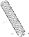
- FIG. 13 is a perspective view of a conventional upper roll cleaning member.
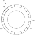
- FIG. 14 is a cross-sectional view of a conventional upper roll cleaning member.
- FIG. 15 is a development view of a basic surface of a conventional upper roll cleaning member.
- FIG. 16 is a development view of a contact surface of a conventional upper roll cleaning member.
- FIG. 15 is a development view of a basic surface of a conventional upper roll cleaning member.
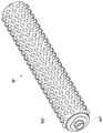
- FIG. 17 is a perspective view of the upper roll cleaning member according to the fifth embodiment of the present invention.
- FIG. 18 is a cross-sectional view of the upper roll cleaning member according to the fifth embodiment of the present invention.
- FIG. 19 is a development view on the basic surface of the upper roll cleaning member according to the fifth embodiment of the present invention.
- FIG. 20 is a development view of the contact surface of the upper roll cleaning member according to the fifth embodiment of the present invention.
- FIG. 7 is a schematic diagram of the roll cleaning apparatus according to the first embodiment.
- the upper roll cleaning member 52 is oscillated (reciprocally translated) in the axial direction by a driving device (not shown).
- a driving device not shown.
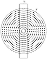
- the position of the nodule (projection member) on the upper roll cleaning member 52 in the radial direction of the substrate W is not fixed, and concentric cleaning unevenness as shown in FIG. 6 can be prevented.
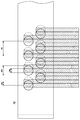
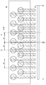
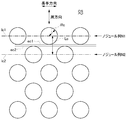
- FIG. 8 is a schematic diagram showing the configuration of the upper roll cleaning member 52.
- the peristaltic pitch (repetition width) of the upper roll cleaning member 52 will be described with reference to FIG.
- the upper roll cleaning member 52 has a cylindrical shape, and a plurality of cylindrical nodules are formed on the surface thereof.
- the plurality of nodules of the upper roll cleaning member 52 are arranged at equal intervals in the row direction, and each row is arranged at equal intervals in the circumferential direction of the upper roll cleaning member 52. Further, the position of a nodule in a certain row and the position of a nodule in a row adjacent thereto are shifted by a half of the interval of nodules in the row direction. That is, the nodules are arranged alternately in each row.
- the nodule diameter is nw
- the arrangement pitch of nodules in the column direction is np
- the region in which scrub cleaning is performed with high cleaning force by contacting the surface of the substrate W with high pressing force (high cleaning force region) 8 is first, the upper roll cleaning member 52 in the example of FIG. 8 satisfies np ⁇ nw ⁇ nw, that is, np ⁇ 2 nw. That is, since the upper roll cleaning member 52 is in sliding contact with the substrate W while rotating, the nodules are in contact with the surface of the substrate W without a gap. However, as shown in FIG. 8, there is a gap between the trajectories of the high detergency areas adjacent in the column direction, and cleaning unevenness occurs as it is. Therefore, in the present embodiment, the roll cleaning member is swung in the longitudinal direction as described above.
- the trajectory of the nodule high cleaning force region is positioned without a gap in the radial direction of the substrate W due to peristaltic movement of the upper roll cleaning member 52. Concentric cleaning unevenness can be prevented.
- the condition of the pitch np in the column direction is sp ⁇ (np / 2) ⁇ (k ⁇ nw).
- the width sa of the high detergency region may be determined by setting k, or may be determined based on actual cleaning unevenness.
- k can be any value from 0.3 to 0.6. That is, the width sa of the high detergency region can be set as 30% to 60% of the width in the column direction of the end face of the nodule (or the diameter of the end face when the end face is a circle).
- the width sa of the high detergency region can be set, for example, as 40% of the width in the column direction of the end face of the nodule. Further, the width sa of the high cleaning power region may be determined based on the cleaning unevenness that occurs when the cleaning is actually performed.
- each nodule is drawn larger than the overall size of the upper roll cleaning member 52, but the ratio of nw, np, sa, and sp is accurately shown in FIG. 8. .
- FIG. 8 only some of the plurality of nodules formed on the upper roll cleaning member 52 are shown, and illustration of some of the nodules in the column direction and the circumferential direction is omitted.
- the locus of the high detergency region on the substrate W is formed concentrically in the shape of the substrate W by the rotation of the substrate W, but this is shown by a straight line in FIG.
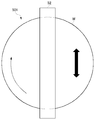
- the upper roll cleaning member 52 is swung in the axial direction, but instead, the substrate W is swung in the axial direction of the upper roll cleaning member 52 as shown in FIG. May be. Further, the upper roll cleaning member 52 may be reciprocally translated not in the axial direction but in other directions, or may be swung around a predetermined pivot axis perpendicular to the substrate W.
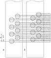
- FIG. 10 is a schematic diagram illustrating a configuration of the upper roll cleaning member according to the second embodiment.
- each nodule is drawn larger than the overall size of the upper roll cleaning member.
- FIG. 10 also shows only some of the plurality of nodules formed on the upper roll cleaning member, and omits some of the nodules in the row direction and the circumferential direction.
- two upper roll cleaning members 521 and 522 are provided for one roll cleaning apparatus, and the surface of the substrate is scrubbed using these in order or simultaneously on the same substrate.
- a plurality of cylindrical nodules are formed on the first upper roll cleaning member 521 and the second upper roll cleaning member 522.
- the plurality of nodules of the first upper roll cleaning member 521 and the second upper roll cleaning member 522 are arranged at equal intervals in the row direction, and each row is arranged at equal intervals in the circumferential direction. Further, the position of a nodule in a certain column and the position of a nodule in a column adjacent to the column are shifted by a half of the interval (np) of the nodules in the column direction.
- the positions of the nodules are shifted by 1/4 (np / 4) of the interval (np) of the nodules in the column direction.
- the center of the high detergency region of the second upper roll cleaning member 522 is positioned in the center of the gap of the high detergency region of the first upper roll cleaning member 521. Therefore, if the high cleaning power region has a width of 1/4 or more of the diameter of the nodule, the substrate is cleaned by using the first upper roll cleaning member 521 and the second upper roll cleaning member 522.
- the high cleaning power region by the second upper roll cleaning member 522 is located in the gap of the locus of the high cleaning power region by the first upper roll cleaning member 521, and the high cleaning without gaps in the radial direction of the substrate is performed. Since the locus of the force region exists, it is possible to prevent occurrence of concentric cleaning unevenness on the substrate.
- FIG. 11 is a schematic diagram illustrating a configuration of the upper roll cleaning member 52 according to the third embodiment.
- each nodule is drawn larger than the overall size of the upper roll cleaning member.
- FIG. 11 also shows only some of the plurality of nodules formed on the upper roll cleaning member, and omits illustration of some of the nodules in the row direction and the circumferential direction.
- a plurality of cylindrical nodules are formed on the upper roll cleaning member 52.
- the plurality of nodules are arranged at equal intervals in the column direction, and each column is arranged at equal intervals in the circumferential direction.
- the upper roll cleaning member 52 of the present embodiment uses m types of nodule rows shifted by 1 / m of the nodule spacing (np) in the row direction from the positions of the nodules based on the positions of the nodules in a row. Have.
- K is determined from the diameter nw of the nodules, the pitch np of the arrangement in the row direction of the nodules, and the width sa in the row direction of the high detergency region as follows. That is, m is an integer obtained by rounding up (np ⁇ sa) / sa + 1. By doing so, the gaps in the high detergency region of the nodule in one row are all covered by the high detergency regions in the other row, and there is a locus of the high detergency region without any gap in the radial direction of the substrate. Thus, concentric cleaning unevenness can be prevented from occurring on the substrate.
- the upper roll cleaning member 52 uses, as a reference, the positions of nodules in a certain row, a plurality of nodules that are shifted from the positions of those nodules by 1/4 of the nodule spacing (np) in the row direction. 4 having a column shifted by 1/4 of the nodule interval (np) in the column direction from the column, and a column further shifted by 1/4 of the nodule interval (np) in the column direction from the column. Has a column of types.
- the nodule string nl1 and the nodule string nl3 are shifted by np / 4, the nodule string nl2 is further shifted by np / 4 from the nodule string nl3, and the nodule string nl4 is further shifted from the nodule string nl2. It is shifted by np / 4.
- the high detergency region due to the nodule in the second row is in the center of the gap between the locus of the high detergency region due to the nodule in the first row and the locus of the high detergency region due to the joule in the third row.
- the center of the locus of the high detergency region due to the nodule in the fourth row are located, so that it is possible to prevent the occurrence of concentric cleaning unevenness on the substrate.
- the arrangement order of the nodule rows nl1 to nl4 in the circumferential direction is not limited to the example of FIG. 11, but another order in the circumferential direction (for example, nodule row nl1, nodule row nl3, nodule row nl2, nodule row nl4 in the circumferential direction). May be arranged in order).
- FIG. 12 is a schematic diagram illustrating a configuration of the upper roll cleaning member 52 according to the fourth embodiment. Also in FIG. 12, each nodule is greatly drawn with respect to the whole size of the upper roll cleaning member. FIG. 12 also shows only some of the plurality of nodules formed on the upper roll cleaning member, and omits illustration of some of the nodules in the row direction and the circumferential direction.
- the arrangement of the nodules of the upper roll cleaning member 52 of the present embodiment is not symmetrical in the longitudinal direction with respect to the position C corresponding to the center of the substrate W. With this configuration, the high cleaning power region by the nodule on one side and the high cleaning power region by the nodule on the other side from the position (reference position) corresponding to the rotation center of the substrate W of the upper roll cleaning member 52. The cleaning unevenness can be prevented or reduced.
- the nodule has a high cleaning power region. Therefore, even with the upper roll cleaning member 52 of the present embodiment, the locus of the high cleaning force region exists in the radial direction of the substrate W without any gap, and the occurrence of concentric cleaning unevenness on the substrate can be prevented.
- the nodule of the upper roll cleaning member 52 is located at the center of the nodule high detergency region at a position A separated from the position C by a distance ra on one side in the longitudinal direction (right side in the example of FIG. 12). If it is, the center of the gap between the adjacent high detergency regions is located at a position A ′ separated by a distance ra on the opposite side (left side in the example of FIG. 12). That is, the distance from the reference position of the plurality of nodules on one side in the longitudinal direction from the reference position of the upper roll cleaning member 52 and the distance from the reference position of the plurality of nodules on the other side in the longitudinal direction from the reference position are np It is shifted by / 4.
- the center of the locus of the high detergency region by the nodule on the other side is located in the center of the gap between the locus of the high detergency region by the nodule on one side of the reference position in the longitudinal direction of the upper roll cleaning member 52. Can be located.
- FIGS. 13 to 16 are views showing a conventional roll cleaning member
- FIG. 13 is a perspective view
- FIG. 14 is a cross-sectional view
- FIG. 15 is a development view on a base surface
- FIG. It is an expanded view in a contact surface. 15 and 16, the left-right direction in the drawing indicates the longitudinal direction of the roll cleaning member, and the up-down direction in the drawing indicates the circumferential direction of the roll cleaning member.
- the upper roll cleaning member 52 ′ is composed of a cylindrical core member 521 ′ and a scrub member 522 ′ covering the surface of the core member 521 ′.
- the scrub member 522 ′ is made of PVA or the like, and a plurality of nodules are formed on the surface thereof.
- the surface of the scrub member 522 ′ where nodules are not formed is referred to as a base surface BS, and the surface formed from the tips of the nodules is referred to as a contact surface CS.
- the nodules project from the base surface BS of the scrub member 522 ′.
- the distance L1 between the nodules in the circumferential direction of the adjacent nodule rows on the base surface BS is smaller than the distance L2 between the nodules in the circumferential direction of the adjacent nodule rows on the contact surface CS.
- the nodules in the nodule row adjacent to each other on the contact surface CS are spaced apart from each other in the circumferential direction, whereby the fluidity of the cleaning liquid between the nodules (fresh cleaning liquid) Enters between the nodules, and the old cleaning liquid is discharged from between the nodules).
- the conventional nodule cleaning member 52 ′ as shown in FIG. 15, the nodules in the adjacent nodule rows are spaced apart from each other in the circumferential direction even on the base surface BS.
- the nodules formed on the roll cleaning member are crushed and deformed by receiving stress in the traveling direction of the substrate when slidingly contacting the surface of the substrate. This stress also reaches a portion (including the vicinity of the base of the nodule) where the nodule of the scrub member 522 ′ is not formed. That is, the hatched portion shown in FIG. 15 also receives stress due to the nodule slidingly contacting the substrate.
- the hatched portion in FIG. 15 is a thin portion where no nodules are formed in the scrub member 522 ′. Although only a part of this thin portion is shown in FIG. 15, this thin portion is formed in a band shape between the nodule rows. By repeatedly applying stress to this thin portion, fatigue accumulates in this portion and deteriorates, leading to cracks and the like.
- the present embodiment provides a roll cleaning member that reduces the deterioration due to fatigue while ensuring the fluidity of the cleaning liquid between the nodules.
- FIG. 17 to 20 are views showing the roll cleaning member of the present embodiment, FIG. 17 is a perspective view, FIG. 18 is a cross-sectional view, and FIG. 19 is a development view on the base surface.
- FIG. 4 is a development view of the contact surface. 19 and 20, the left-right direction in the drawing indicates the longitudinal direction of the roll cleaning member, and the up-down direction in the drawing indicates the circumferential direction of the roll cleaning member.
- the upper roll cleaning member 52 ′′ includes a cylindrical core member 521 ′′ and a scrub member 522 ′′ that covers the surface of the core member 521 ′′.
- the scrub member 522 ′′ is made of PVA or the like, and a plurality of nodules are formed on the surface thereof.
- nodules are arranged in a straight line at equal intervals in the longitudinal direction of the upper roll cleaning member 52 ′′, and a plurality of nodule arrays Is forming.
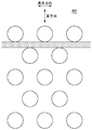
- the positions of the plurality of nodules in the nodule row adjacent to each other in the circumferential direction of the upper roll cleaning member 52 ′′ are shifted from each other by half the pitch of the nodules in the nodule row in the longitudinal direction, and are uniform in the circumferential direction on the base surface BS. Overlapping parts. That is, as shown in FIG.
- each nodule in the first nodule array N1 and a part of each nodule in the second nodule array N2 are alternately present.
- the plurality of nodules in each nodule row are staggered in the longitudinal direction between the nodule rows adjacent in the circumferential direction on the base surface BS, and partially overlap in the circumferential direction.
- a region where neither the nodules in the first nodule row N1 nor the nodules in the second nodule row N2 exist is formed in a strip shape in the longitudinal direction.
- the above relationship can be expressed in other ways. That is, focusing on two adjacent nodule rows among a plurality of nodule rows arranged in a straight line in the longitudinal direction, for example, as shown in FIG. A straight line lc1 passing through the center of a plurality of nodule circles constituting the nodule row N1 , and (2) a plurality of nodule circles constituting the second nodule row N2 adjacent to the first nodule row N1 in the circumferential direction.
- the shortest distance Lc between the straight line lc2 passing through the center of the nodule and the radius Rc of the nodules constituting the first nodule row N1 and the second nodule row N2 in FIG. 20, the case of nodules having the same radius is shown.
- the average length of the nodule radii on the contact surface CS is selected as Rc).
- the interval between the nodules in the circumferential direction is narrower than that of the conventional upper roll cleaning member 52 ′, and the surface of the substrate is slidably contacted even at the same rotational speed.
- the number of nodules has increased from the conventional level, and the detergency increases.
- the upper roll cleaning member 52 ′′ of the present embodiment also has better resistance to stress fatigue than the conventional upper roll cleaning member 52 ′.
- the nodules in adjacent nodule rows are arranged so as to partially overlap each other in the circumferential direction, and the thin portion where no nodules are formed in the scrub member 522 ′′ has a continuous band shape. This is probably because it is not. With such an arrangement, even when the nodule is deformed when sliding on the surface of the substrate and stress is applied to the thin-walled portion, such a portion becomes discontinuous and the stress due to the nodules adjacent in the column direction is dispersed. Is done.
- the distance between the nodules in the circumferential direction is larger than the distance between the nodules in the circumferential direction on the base surface BS.
- the upper roll cleaning member 52 ′ the nodules in the nodule row adjacent to each other in the circumferential direction are separated from each other. This ensures fluidity between the nodules of the cleaning liquid supplied to the surface of the substrate.
- the cleaning performance is improved and the deterioration due to fatigue can be reduced while ensuring the fluidity of the cleaning liquid between the nodules.
- the shape of the nodule is a cylindrical shape.
- the shape of the nodule is not limited to this, and for example, other shapes such as a quadrangular prism shape may be used. Good.
- the nodule is formed in the upper roll cleaning member 52, and the configuration for preventing or reducing the uneven cleaning generated on the upper surface of the substrate W has been described. Even in the case where nodules are formed on the member 53, it is possible to prevent or reduce the uneven cleaning generated on the lower surface of the substrate W by adopting the same configuration as described above.
- nodules are formed in the upper roll cleaning member 52, and the cleaning performance is improved while ensuring the fluidity of the cleaning liquid between the nodules, and deterioration due to fatigue can be reduced.
- the same configuration as described above can be used when nodules are formed in the lower roll cleaning member 53.
- This technique has an effect of reducing or preventing concentric cleaning unevenness generated on the substrate because the substrate is cleaned such that the high detergency region of the nodule exists without gaps in the radial direction of the substrate. It is useful as a roll cleaning member that contacts the surface and cleans the substrate, and a cleaning device including the roll cleaning member.
- Roll Cleaning Device 51 Spindle 51a Top 52 Upper Roll Cleaning Member 521 First Upper Roll Cleaning Member 522 Second Upper Roll Cleaning Member 52 ′, 52 ′′ Upper Roll Cleaning Member 521 ′, 521 ′′ Core Material 522 ′, 522 ′′ Scrub member 53 Lower roll cleaning member 54 Cleaning liquid supply nozzle 55 Cleaning liquid supply nozzle nw Nodule diameter np Pitch in arrangement of nodules in row direction sa Width in row direction of high cleaning force region sp Peristaltic pitch (amplitude of reciprocal translation) ) BS base surface CS contact surface
Landscapes
- Chemical & Material Sciences (AREA)
- Chemical Kinetics & Catalysis (AREA)
- General Chemical & Material Sciences (AREA)
- Cleaning Or Drying Semiconductors (AREA)
- Photoreceptors In Electrophotography (AREA)
- Rolls And Other Rotary Bodies (AREA)
- Cleaning In General (AREA)
Abstract
Description
Lc>2Rc ・・・(1)
ここで、Lcは、接触面における、第1の突起部材列を構成する複数の突起部材の円の中心を通る直線と、第1の突起部材列と周方向に隣り合う第2の突起部材列を構成する複数の突起部材の円の中心を通る直線との間の最短距離と定義される。
また、Rcは、接触面における、複数の突起部材列を構成する複数の突起部材の半径の平均長と定義される。
Lb<2Rb ・・・(2)
ここで、Lbは、基礎面における、第1の突起部材列を構成する複数の突起部材の円の中心を通る直線と、第1の突起部材列と周方向に隣り合う第2の突起部材列を構成する複数の突起部材の円の中心を通る直線との間の最短距離と定義される。
また、Rbは、基礎面における、複数の突起部材列を構成する複数の突起部材の半径の平均長と定義される。
図7は、第1の実施の形態のロール洗浄装置の模式図である。図7では、基板Wと上部ロール洗浄部材52のみを図示している。本実施の形態のロール洗浄装置501では、上部ロール洗浄部材52を図示しない駆動装置によってその軸方向に搖動(往復平行移動)させる。これによって、上部ロール洗浄部材52上のノジュール(突起部材)の基板Wの半径方向の位置が固定されず、図6に示したような同心円状の洗浄むらを防止できる。
図10は、第2の実施の形態の上部ロール洗浄部材の構成を示す模式図である。なお、図10でも、上部ロール洗浄部材の全体の大きさに対して各ノジュールを大きく描いている。また、図10でも、上部ロール洗浄部材に形成される複数のノジュールの一部のみを示し、列方向及び周方向の一部のノジュールの図示を省略している。
図11は、第3の実施の形態の上部ロール洗浄部材52の構成を示す模式図である。なお、図11でも、上部ロール洗浄部材の全体の大きさに対して各ノジュールを大きく描いている。また、図11でも、上部ロール洗浄部材に形成される複数のノジュールの一部のみを示し、列方向及び周方向の一部のノジュールの図示を省略している。
図12は、第4の実施の形態の上部ロール洗浄部材52の構成を示す模式図である。図12でも、上部ロール洗浄部材の全体の大きさに対して各ノジュールを大きく描いている。また、図12でも、上部ロール洗浄部材に形成される複数のノジュールの一部のみを示し、列方向及び周方向の一部のノジュールの図示を省略している。
図13~図16は、いずれも従来のロール洗浄部材を示す図であり、図13は斜視図であり、図14は断面図であり、図15は基礎面における展開図であり、図16は接触面における展開図である。なお、図15及び図16において、図の左右方向がロール洗浄部材の長手方向を示し、図の上下方向がロール洗浄部材の周方向を表す。
51 スピンドル
51a コマ
52 上部ロール洗浄部材
521 第1の上部ロール洗浄部材
522 第2の上部ロール洗浄部材
52´、52´´ 上部ロール洗浄部材
521´、521´´ 芯材
522´、522´´ スクラブ部材
53 下部ロール洗浄部材
54 洗浄液供給ノズル
55 洗浄液供給ノズル
nw ノジュールの径
np ノジュールの列方向の配置のピッチ
sa 高洗浄力領域の列方向の幅
sp 搖動ピッチ(往復平行移動の振幅)
BS 基礎面
CS 接触面
Claims (19)
- 基板を支持して回転させる基板支持部材と、
前記基板支持部材によって回転される前記基板の表面を回転しながらスクラブ洗浄するためのロール洗浄部材とを備え、
前記ロール洗浄部材は、その長手方向に配列され、前記基板の表面に摺接する複数の突起部材を備え、
前記突起部材における前記基板に摺接する部分のうちの高洗浄力領域の軌跡が前記基板の半径方向に隙間なく存在するように前記基板を洗浄することを特徴とする洗浄装置。 - 前記高洗浄力領域は、前記突起部材と前記基板の表面との接触領域の30%~60%のいずれかの幅として設定されることを特徴とする請求項1に記載の洗浄装置。
- 前記複数の突起部材は、前記ロール洗浄部材の長手方向に等間隔で配置されて複数の突起部材列を形成しており、かつ、前記ロール洗浄部材の周方向に隣り合う突起部材列の複数の突起部材の位置は、互いに前記突起部材列における前記突起部材のピッチの半分だけずれていることを特徴とする請求項1又は2に記載の洗浄装置。
- 前記複数の突起部材の前記高洗浄力領域が前記基板に摺接したときの複数の軌跡の間には互いに半径方向に隙間があり、
前記ロール洗浄部材と回転する前記基板とを洗浄中に相対的に搖動させることで、前記高洗浄力領域の複数の軌跡が前記基板の半径方向に隙間なく存在するように前記基板を洗浄することを特徴とする請求項3に記載の洗浄装置。 - 前記ロール洗浄部材の搖動ピッチspは、前記突起部材列における前記複数の突起部材のピッチをnp、前記高洗浄力領域の前記長手方向の幅をsaとすると、sp≧(np/2)-saを満たすことを特徴とする請求項4に記載の洗浄装置。
- 第1のロール洗浄部材及び第2のロール洗浄部材を含む2つの前記ロール洗浄部材を備え、
前記第1のロール洗浄部材及び前記第2のロール洗浄部材において、前記複数の突起部材は、前記ロール洗浄部材の長手方向に等間隔で配置されて複数の突起部材列を形成しており、かつ、前記ロール洗浄部材の周方向に隣り合う突起部材列の複数の突起部材の位置は、互いに前記突起部材列における前記突起部材のピッチの半分だけずれていることを特徴とする請求項1又は2に記載の洗浄装置。 - 前記第1のロール洗浄部材及び前記第2のロール洗浄部材において、前記突起部材列における前記突起部材のピッチをnpとすると、前記基板を洗浄するときの前記第1のロール洗浄部材の前記複数の突起部材の位置と前記基板を洗浄するときの前記第2のロール洗浄部材の前記複数の突起部材の位置とは、列方向にnp/4だけずれていることを特徴とする請求項6に記載の洗浄装置。
- 前記複数の突起部材は、前記長手方向の第1の列にピッチnpで並ぶ複数の突起部材と、前記長手方向の第2の列にピッチnpで並ぶ複数の突起部材と、前記長手方向の第3の列にピッチnpで並ぶ複数の突起部材と、前記長手方向の第4の列にピッチnpで並ぶ複数の突起部材とを含み、
前記第1の列に並ぶ複数の突起部材の前記長手方向の位置と前記第2の列に並ぶ複数の突起部材の前記長手方向とは、np/4だけずれており、前記第2の列に並ぶ複数の突起部材の前記長手方向の位置と前記第3の列に並ぶ複数の突起部材の前記長手方向とは、np/4だけずれており、前記第3の列に並ぶ複数の突起部材の前記長手方向の位置と前記第4の列に並ぶ複数の突起部材の前記長手方向とは、np/4だけずれていることを特徴とする請求項1又は2に記載の洗浄装置。 - 前記ロール洗浄部材は、回転する前記基板の回転中心を通って前記回転中心から両側の基板の外周まで至る範囲で前記基板に摺接し、
前記複数の突起部材は、前記回転中心に対応する位置を基準として両側に非対称に配置されることを特徴とする請求項1又は2に記載の洗浄装置。 - 前記複数の突起部材は、前記回転中心に対応する位置より前記長手方向の一方側の複数の前記突起部材の、前記回転中心に対応する位置からの距離と、前記回転中心に対応する位置より前記長手方向の他方側の複数の前記突起部材の、前記回転中心に対応する位置からの距離とは、np/4だけずれていることを特徴とする請求項9に記載の洗浄装置。
- 基板を支持して回転させる基板支持部材と、
前記基板支持部材によって回転する前記基板の表面を回転しながらスクラブ洗浄するためのロール洗浄部材とを備え、
前記ロール洗浄部材は、その長手方向に等間隔で配列され、前記基板の表面に摺接する複数の突起部材を備え、
前記複数の突起部材は、前記ロール洗浄部材の長手方向に配置されて複数の突起部材列を形成しており、かつ、前記ロール洗浄部材の周方向に隣り合う突起部材列の複数の突起部材の位置は、互いに前記突起部材列における前記突起部材のピッチの半分だけずれており、
前記複数の突起部材の前記高洗浄力領域が前記基板に摺接したときの軌跡の間には互いに隙間があり、
洗浄中に、前記ロール洗浄部材と前記基板支持部材によって回転する前記基板とを相対的に搖動させることを特徴とする洗浄装置。 - 基板を支持して回転させる基板支持部材と、
前記基板支持部材によって回転する前記基板の表面を回転しながらスクラブ洗浄するための第1のロール洗浄部材と、
前記基板支持部材によって回転する前記基板の表面をスクラブ洗浄するための第2のロール洗浄部材とを備え、
前記第1のロール洗浄部材及び前記第2のロール洗浄部材は、それぞれ、その長手方向に配列され、前記基板の表面に摺接する複数の突起部材を備え、
前記第1のロール洗浄部材及び前記第2のロール洗浄部材において、前記複数の突起部材は、前記ロール洗浄部材の長手方向に等間隔で配置されて複数の突起部材列を形成しており、かつ、前記ロール洗浄部材の周方向に隣り合う突起部材列の複数の突起部材の位置は、互いに前記突起部材列における前記突起部材のピッチの半分だけずれていることを特徴とする洗浄装置。 - 基板を支持して回転させる基板支持部材と、
前記基板支持部材によって回転する前記基板の表面を回転しながらスクラブ洗浄するためのロール洗浄部材とを備え、
前記ロール洗浄部材は、その長手方向に配列され、前記基板の表面に摺接する複数の突起部材を備え、
前記複数の突起部材は、前記長手方向の第1の列にピッチnpで並ぶ複数の突起部材と、前記長手方向の第2の列にピッチnpで並ぶ複数の突起部材と、前記長手方向の第3の列にピッチnpで並ぶ複数の突起部材と、前記長手方向の第4の列にピッチnpで並ぶ複数の突起部材とを含み、
前記第1の列に並ぶ複数の突起部材の前記長手方向の位置と前記第2の列に並ぶ複数の突起部材の前記長手方向とは、np/4だけずれており、前記第2の列に並ぶ複数の突起部材の前記長手方向の位置と前記第3の列に並ぶ複数の突起部材の前記長手方向とは、np/4だけずれており、前記第3の列に並ぶ複数の突起部材の前記長手方向の位置と前記第4の列に並ぶ複数の突起部材の前記長手方向とは、np/4だけずれていることを特徴とする洗浄装置。 - 基板を支持して回転させる基板支持部材と、
前記基板支持部材によって回転する前記基板の表面を回転しながらスクラブ洗浄するためのロール洗浄部材とを備え、
前記ロール洗浄部材は、その長手方向に配列され、前記基板の表面に摺接する複数の突起部材を備え、
前記ロール洗浄部材は、回転する前記基板の回転中心を通って前記回転中心から両側の基板の外周まで至る範囲で前記基板に摺接し、
前記複数の突起部材は、前記回転中心に対応する位置を境に両側に非対称に配置されることを特徴とする洗浄装置。 - 基板を支持して回転させる基板支持部材と、
前記基板支持部材によって回転される前記基板の表面を回転しながらスクラブ洗浄するためのロール洗浄部材とを備え、
前記ロール洗浄部材は、その長手方向に配列され、前記基板の表面に摺接する複数の突起部材を備え、
前記複数の突起部材は、前記ロール洗浄部材の長手方向に配置されて複数の突起部材列を形成しており、かつ、前記ロール洗浄部材の周方向に隣り合う突起部材列の複数の突起部材の位置は互いに前記長手方向にずれており、
前記ロール洗浄部材は、前記突起部材が突設される基礎面において、周方向に隣り合う突起部材列の複数の突起部材は、互いに一部が周方向に重なっており、かつ、前記突起部材の接触面において、周方向に隣り合う突起部材列の複数の突起部材は、互いに周方向に離間していることを特徴とする洗浄装置。 - 回転する基板の表面を回転しながらスクラブ洗浄するためのロール洗浄部材であって、
前記ロール洗浄部材の長手方向に配列され、前記基板の表面に摺接する複数の突起部材を備え、
前記複数の突起部材は、前記長手方向の第1の列にピッチnpで並ぶ複数の突起部材と、前記長手方向の第2の列に前記ピッチnpで並ぶ複数の突起部材と、前記長手方向の第3の列に前記ピッチnpで並ぶ複数の突起部材と、前記長手方向の第4の列に前記ピッチnpで並ぶ複数の突起部材とを含み、
前記第1の列に並ぶ複数の突起部材の前記長手方向の位置と前記第2の列に並ぶ複数の突起部材の前記長手方向とは、np/4だけずれており、前記第2の列に並ぶ複数の突起部材の前記長手方向の位置と前記第3の列に並ぶ複数の突起部材の前記長手方向とは、np/4だけずれており、前記第3の列に並ぶ複数の突起部材の前記長手方向の位置と前記第4の列に並ぶ複数の突起部材の前記長手方向とは、np/4だけずれていることを特徴とするロール洗浄部材。 - 回転する基板の表面を回転しながらスクラブ洗浄するためのロール洗浄部材であって、
前記ロール洗浄部材の長手方向に配列され、前記基板の表面に摺接する複数の突起部材を備え、
前記ロール洗浄部材は、回転する前記基板の回転中心を通って前記回転中心から両側の基板の外周まで至る範囲で前記基板に摺接し、
前記複数の突起部材は、前記回転中心に対応する位置を境に両側に非対称に配置されることを特徴とするロール洗浄部材。 - 回転する基板の表面を回転しながらスクラブ洗浄するためのロール洗浄部材であって、
前記ロール洗浄部材の長手方向に配列され、前記基板の表面に摺接する複数の突起部材を備え、
前記複数の突起部材は、前記ロール洗浄部材の長手方向に配置されて複数の突起部材列を形成しており、かつ、前記ロール洗浄部材の周方向に隣り合う突起部材列の複数の突起部材の位置は互いに前記長手方向にずれており、
前記ロール洗浄部材は、前記突起部材が突設される基礎面において、周方向に隣り合う突起部材列の複数の突起部材は、互いに一部が周方向に重なっており、かつ、前記突起部材の接触面において、周方向に隣り合う突起部材列の複数の突起部材は、互いに周方向に離間していることを特徴とするロール洗浄部材。 - 回転する基板の表面を洗浄するためのロール洗浄部材であって、
前記基板の表面に摺接し筒形状を有する複数の突起部材を備え、
前記複数の突起部材は、前記ロール洗浄部材の長手方向に一直線上に配列された複数の突起部材列を形成するように配列され、
複数の突起部材列を構成する各突起部材は、
Lc>2Rc、及び
Lb<2Rb
を満たす位置に配置され、
ここで、Lcは、前記突起部材の接触面における、第1の突起部材列を構成する複数の突起部材の円の中心を通る直線と、第1の突起部材列と周方向に隣り合う第2の突起部材列を構成する複数の突起部材の円の中心を通る直線との間の最短距離であり、
Rcは、前記突起部材の接触面における、第1の突起部材列を構成する複数の突起部材の半径の平均長であり、
Lbは、前記突起部材が突設される基礎面における、複数の突起部材列を構成する複数の突起部材の円の中心を通る直線と、第1の突起部材列と周方向に隣り合う第2の突起部材列を構成する複数の突起部材の円の中心を通る直線との間の最短距離であり、
Rbは、前記突起部材が突設される基礎面における、複数の突起部材列を構成する複数の突起部材の半径の平均長である
ことを特徴とするロール洗浄部材。
Priority Applications (5)
| Application Number | Priority Date | Filing Date | Title |
|---|---|---|---|
| KR1020177002741A KR102282899B1 (ko) | 2014-07-04 | 2015-07-01 | 세정 장치 및 롤 세정 부재 |
| MYPI2016704827A MY176791A (en) | 2014-07-04 | 2015-07-01 | Cleaning device and roll cleaning member |
| CN201580036679.2A CN106663620B (zh) | 2014-07-04 | 2015-07-01 | 清洗装置及滚筒清洗部件 |
| SG11201700026XA SG11201700026XA (en) | 2014-07-04 | 2015-07-01 | Cleaning device and roll cleaning member |
| US15/322,480 US10453708B2 (en) | 2014-07-04 | 2015-07-01 | Cleaning device and roll cleaning member |
Applications Claiming Priority (4)
| Application Number | Priority Date | Filing Date | Title |
|---|---|---|---|
| JP2014138685 | 2014-07-04 | ||
| JP2014-138685 | 2014-07-04 | ||
| JP2015-129639 | 2015-06-29 | ||
| JP2015129639A JP6366544B2 (ja) | 2014-07-04 | 2015-06-29 | 洗浄装置及びロール洗浄部材 |
Publications (1)
| Publication Number | Publication Date |
|---|---|
| WO2016002219A1 true WO2016002219A1 (ja) | 2016-01-07 |
Family
ID=55018792
Family Applications (1)
| Application Number | Title | Priority Date | Filing Date |
|---|---|---|---|
| PCT/JP2015/003314 Ceased WO2016002219A1 (ja) | 2014-07-04 | 2015-07-01 | 洗浄装置及びロール洗浄部材 |
Country Status (8)
| Country | Link |
|---|---|
| US (1) | US10453708B2 (ja) |
| JP (1) | JP6366544B2 (ja) |
| KR (1) | KR102282899B1 (ja) |
| CN (1) | CN106663620B (ja) |
| MY (1) | MY176791A (ja) |
| SG (1) | SG11201700026XA (ja) |
| TW (1) | TWI686868B (ja) |
| WO (1) | WO2016002219A1 (ja) |
Families Citing this family (21)
| Publication number | Priority date | Publication date | Assignee | Title |
|---|---|---|---|---|
| US10269555B2 (en) * | 2015-09-30 | 2019-04-23 | Taiwan Semiconductor Manufacturing Company, Ltd. | Post-CMP cleaning and apparatus |
| WO2019138881A1 (ja) * | 2018-01-09 | 2019-07-18 | 東京エレクトロン株式会社 | 洗浄装置、洗浄方法及びコンピュータ記憶媒体 |
| USD923890S1 (en) * | 2018-09-07 | 2021-06-29 | Maradyne Corporation | Mattress surface cleaning agitator |
| CN109007900B (zh) * | 2018-09-20 | 2023-09-12 | 安徽科技学院 | 一种海带无损伤清洗装置及其清洗方法 |
| JP7564811B2 (ja) * | 2019-01-31 | 2024-10-09 | アプライド マテリアルズ インコーポレイテッド | 基板洗浄デバイス及び基板洗浄方法 |
| USD906681S1 (en) * | 2019-03-11 | 2021-01-05 | Ali Ebrahimi Afrouzi | Side brush |
| USD906682S1 (en) * | 2019-03-11 | 2021-01-05 | Ali Ebrahimi Afrouzi | Side brush |
| USD906680S1 (en) * | 2019-03-11 | 2021-01-05 | Ali Ebrahimi Afrouzi | Side brush |
| USD906683S1 (en) * | 2019-03-11 | 2021-01-05 | Ali Ebrahimi Afrouzi | Side brush |
| USD897111S1 (en) * | 2019-03-11 | 2020-09-29 | Ali Ebrahimi Afrouzi | Side brush |
| USD897112S1 (en) * | 2019-03-25 | 2020-09-29 | Ali Ebrahimi Afrouzi | Side brush |
| USD906684S1 (en) * | 2019-03-28 | 2021-01-05 | Ali Ebrahimi Afrouzi | Side brush |
| USD906685S1 (en) * | 2019-04-02 | 2021-01-05 | Ali Ebrahimi Afrouzi | Side brush |
| USD907370S1 (en) * | 2019-04-05 | 2021-01-12 | Ali Ebrahimi Afrouzi | Side brush |
| USD907925S1 (en) * | 2019-04-23 | 2021-01-19 | Ali Ebrahimi Afrouzi | Side brush |
| USD897113S1 (en) * | 2019-04-25 | 2020-09-29 | Ali Ebrahimi Afrouzi | Side brush |
| USD906686S1 (en) * | 2019-04-30 | 2021-01-05 | Ali Ebrahimi Afrouzi | Side brush |
| USD907371S1 (en) * | 2019-05-03 | 2021-01-12 | Ali Ebrahimi Afrouzi | Side brush |
| USD907926S1 (en) * | 2019-06-10 | 2021-01-19 | Ali Ebrahimi Afrouzi | Side brush |
| USD907372S1 (en) * | 2019-06-10 | 2021-01-12 | Ali Ebrahimi Afrouzi | Side brush |
| CN111790682B (zh) * | 2020-06-30 | 2022-06-28 | 鹰潭拓新机电股份有限公司 | 一种模具零件清洗装置 |
Citations (5)
| Publication number | Priority date | Publication date | Assignee | Title |
|---|---|---|---|---|
| JP2000270929A (ja) * | 1999-03-26 | 2000-10-03 | Shibaura Mechatronics Corp | 洗浄用ブラシ |
| JP2006075718A (ja) * | 2004-09-09 | 2006-03-23 | Aion Kk | 弾性ローラ |
| JP2008311481A (ja) * | 2007-06-15 | 2008-12-25 | Sony Corp | 基板洗浄方法、基板洗浄装置及び半導体製造方法 |
| JP2009066527A (ja) * | 2007-09-13 | 2009-04-02 | Nec Electronics Corp | 洗浄用ローラおよび洗浄装置 |
| JP2011233646A (ja) * | 2010-04-26 | 2011-11-17 | Sumitomo Metal Mining Co Ltd | 半導体用基板の洗浄方法 |
Family Cites Families (8)
| Publication number | Priority date | Publication date | Assignee | Title |
|---|---|---|---|---|
| US6502273B1 (en) | 1996-11-08 | 2003-01-07 | Kanebo, Ltd. | Cleaning sponge roller |
| JP3403108B2 (ja) * | 1999-02-26 | 2003-05-06 | アイオン株式会社 | 洗浄用スポンジローラ |
| US6299698B1 (en) | 1998-07-10 | 2001-10-09 | Applied Materials, Inc. | Wafer edge scrubber and method |
| JP4965253B2 (ja) * | 2003-08-08 | 2012-07-04 | インテグリス・インコーポレーテッド | 回転可能ベース上に鋳造されるモノリシック多孔性パッドを作製する方法および材料 |
| US20050109371A1 (en) * | 2003-10-27 | 2005-05-26 | Applied Materials, Inc. | Post CMP scrubbing of substrates |
| US20100043160A1 (en) * | 2008-08-20 | 2010-02-25 | United Microelectronics Corp. | Wafer cleaning roller |
| US20130048018A1 (en) | 2010-02-22 | 2013-02-28 | Entegris, Inc. | Post-cmp cleaning brush |
| JP5535687B2 (ja) | 2010-03-01 | 2014-07-02 | 株式会社荏原製作所 | 基板洗浄方法及び基板洗浄装置 |
-
2015
- 2015-06-29 JP JP2015129639A patent/JP6366544B2/ja active Active
- 2015-07-01 CN CN201580036679.2A patent/CN106663620B/zh active Active
- 2015-07-01 SG SG11201700026XA patent/SG11201700026XA/en unknown
- 2015-07-01 KR KR1020177002741A patent/KR102282899B1/ko active Active
- 2015-07-01 MY MYPI2016704827A patent/MY176791A/en unknown
- 2015-07-01 WO PCT/JP2015/003314 patent/WO2016002219A1/ja not_active Ceased
- 2015-07-01 US US15/322,480 patent/US10453708B2/en active Active
- 2015-07-03 TW TW104121628A patent/TWI686868B/zh active
Patent Citations (5)
| Publication number | Priority date | Publication date | Assignee | Title |
|---|---|---|---|---|
| JP2000270929A (ja) * | 1999-03-26 | 2000-10-03 | Shibaura Mechatronics Corp | 洗浄用ブラシ |
| JP2006075718A (ja) * | 2004-09-09 | 2006-03-23 | Aion Kk | 弾性ローラ |
| JP2008311481A (ja) * | 2007-06-15 | 2008-12-25 | Sony Corp | 基板洗浄方法、基板洗浄装置及び半導体製造方法 |
| JP2009066527A (ja) * | 2007-09-13 | 2009-04-02 | Nec Electronics Corp | 洗浄用ローラおよび洗浄装置 |
| JP2011233646A (ja) * | 2010-04-26 | 2011-11-17 | Sumitomo Metal Mining Co Ltd | 半導体用基板の洗浄方法 |
Also Published As
| Publication number | Publication date |
|---|---|
| US20170170034A1 (en) | 2017-06-15 |
| SG11201700026XA (en) | 2017-02-27 |
| KR102282899B1 (ko) | 2021-07-27 |
| TW201604962A (zh) | 2016-02-01 |
| US10453708B2 (en) | 2019-10-22 |
| CN106663620A (zh) | 2017-05-10 |
| JP2016027641A (ja) | 2016-02-18 |
| TWI686868B (zh) | 2020-03-01 |
| CN106663620B (zh) | 2020-03-27 |
| KR20170029536A (ko) | 2017-03-15 |
| JP6366544B2 (ja) | 2018-08-01 |
| MY176791A (en) | 2020-08-21 |
Similar Documents
| Publication | Publication Date | Title |
|---|---|---|
| JP6366544B2 (ja) | 洗浄装置及びロール洗浄部材 | |
| JP5886224B2 (ja) | 基板洗浄方法 | |
| TWI590319B (zh) | 化學機械研磨後清洗及設備 | |
| TWI670141B (zh) | 滾筒構件、以及基板洗淨方法 | |
| TWI443732B (zh) | 化學機械研磨後晶圓清洗裝置 | |
| JP5645752B2 (ja) | 基板洗浄方法及びロール洗浄部材 | |
| CN107078046B (zh) | 基板清洗辊、基板清洗装置及基板清洗方法 | |
| TWI652732B (zh) | 刷洗方法及刷洗裝置 | |
| CN110957208A (zh) | 晶圆洗边方法及晶圆清洗装置 | |
| WO2022186227A1 (ja) | ブラシローラ | |
| KR20150103460A (ko) | 화학 기계적 연마 공정이 행해진 기판의 세정 장치 |
Legal Events
| Date | Code | Title | Description |
|---|---|---|---|
| 121 | Ep: the epo has been informed by wipo that ep was designated in this application |
Ref document number: 15814123 Country of ref document: EP Kind code of ref document: A1 |
|
| WWE | Wipo information: entry into national phase |
Ref document number: 15322480 Country of ref document: US |
|
| NENP | Non-entry into the national phase |
Ref country code: DE |
|
| ENP | Entry into the national phase |
Ref document number: 20177002741 Country of ref document: KR Kind code of ref document: A |
|
| WWE | Wipo information: entry into national phase |
Ref document number: 1020177002741 Country of ref document: KR |
|
| 122 | Ep: pct application non-entry in european phase |
Ref document number: 15814123 Country of ref document: EP Kind code of ref document: A1 |