WO2015199227A1 - ガス濃縮方法 - Google Patents
ガス濃縮方法 Download PDFInfo
- Publication number
- WO2015199227A1 WO2015199227A1 PCT/JP2015/068534 JP2015068534W WO2015199227A1 WO 2015199227 A1 WO2015199227 A1 WO 2015199227A1 JP 2015068534 W JP2015068534 W JP 2015068534W WO 2015199227 A1 WO2015199227 A1 WO 2015199227A1
- Authority
- WO
- WIPO (PCT)
- Prior art keywords
- pressure
- adsorption
- adsorption tower
- gas
- state
- Prior art date
- Legal status (The legal status is an assumption and is not a legal conclusion. Google has not performed a legal analysis and makes no representation as to the accuracy of the status listed.)
- Ceased
Links
Images


Classifications
-
- B—PERFORMING OPERATIONS; TRANSPORTING
- B01—PHYSICAL OR CHEMICAL PROCESSES OR APPARATUS IN GENERAL
- B01D—SEPARATION
- B01D53/00—Separation of gases or vapours; Recovering vapours of volatile solvents from gases; Chemical or biological purification of waste gases, e.g. engine exhaust gases, smoke, fumes, flue gases, aerosols
- B01D53/02—Separation of gases or vapours; Recovering vapours of volatile solvents from gases; Chemical or biological purification of waste gases, e.g. engine exhaust gases, smoke, fumes, flue gases, aerosols by adsorption, e.g. preparative gas chromatography
- B01D53/04—Separation of gases or vapours; Recovering vapours of volatile solvents from gases; Chemical or biological purification of waste gases, e.g. engine exhaust gases, smoke, fumes, flue gases, aerosols by adsorption, e.g. preparative gas chromatography with stationary adsorbents
- B01D53/047—Pressure swing adsorption
-
- C—CHEMISTRY; METALLURGY
- C10—PETROLEUM, GAS OR COKE INDUSTRIES; TECHNICAL GASES CONTAINING CARBON MONOXIDE; FUELS; LUBRICANTS; PEAT
- C10L—FUELS NOT OTHERWISE PROVIDED FOR; NATURAL GAS; SYNTHETIC NATURAL GAS OBTAINED BY PROCESSES NOT COVERED BY SUBCLASSES C10G OR C10K; LIQUIFIED PETROLEUM GAS; USE OF ADDITIVES TO FUELS OR FIRES; FIRE-LIGHTERS
- C10L3/00—Gaseous fuels; Natural gas; Synthetic natural gas obtained by processes not covered by subclass C10G, C10K; Liquefied petroleum gas
- C10L3/06—Natural gas; Synthetic natural gas obtained by processes not covered by C10G, C10K3/02 or C10K3/04
- C10L3/10—Working-up natural gas or synthetic natural gas
- C10L3/101—Removal of contaminants
-
- C—CHEMISTRY; METALLURGY
- C10—PETROLEUM, GAS OR COKE INDUSTRIES; TECHNICAL GASES CONTAINING CARBON MONOXIDE; FUELS; LUBRICANTS; PEAT
- C10L—FUELS NOT OTHERWISE PROVIDED FOR; NATURAL GAS; SYNTHETIC NATURAL GAS OBTAINED BY PROCESSES NOT COVERED BY SUBCLASSES C10G OR C10K; LIQUIFIED PETROLEUM GAS; USE OF ADDITIVES TO FUELS OR FIRES; FIRE-LIGHTERS
- C10L3/00—Gaseous fuels; Natural gas; Synthetic natural gas obtained by processes not covered by subclass C10G, C10K; Liquefied petroleum gas
- C10L3/06—Natural gas; Synthetic natural gas obtained by processes not covered by C10G, C10K3/02 or C10K3/04
- C10L3/10—Working-up natural gas or synthetic natural gas
- C10L3/101—Removal of contaminants
- C10L3/102—Removal of contaminants of acid contaminants
- C10L3/104—Carbon dioxide
-
- C—CHEMISTRY; METALLURGY
- C10—PETROLEUM, GAS OR COKE INDUSTRIES; TECHNICAL GASES CONTAINING CARBON MONOXIDE; FUELS; LUBRICANTS; PEAT
- C10L—FUELS NOT OTHERWISE PROVIDED FOR; NATURAL GAS; SYNTHETIC NATURAL GAS OBTAINED BY PROCESSES NOT COVERED BY SUBCLASSES C10G OR C10K; LIQUIFIED PETROLEUM GAS; USE OF ADDITIVES TO FUELS OR FIRES; FIRE-LIGHTERS
- C10L3/00—Gaseous fuels; Natural gas; Synthetic natural gas obtained by processes not covered by subclass C10G, C10K; Liquefied petroleum gas
- C10L3/06—Natural gas; Synthetic natural gas obtained by processes not covered by C10G, C10K3/02 or C10K3/04
- C10L3/10—Working-up natural gas or synthetic natural gas
- C10L3/101—Removal of contaminants
- C10L3/105—Removal of contaminants of nitrogen
-
- B—PERFORMING OPERATIONS; TRANSPORTING
- B01—PHYSICAL OR CHEMICAL PROCESSES OR APPARATUS IN GENERAL
- B01D—SEPARATION
- B01D2253/00—Adsorbents used in seperation treatment of gases and vapours
- B01D2253/10—Inorganic adsorbents
- B01D2253/102—Carbon
-
- B—PERFORMING OPERATIONS; TRANSPORTING
- B01—PHYSICAL OR CHEMICAL PROCESSES OR APPARATUS IN GENERAL
- B01D—SEPARATION
- B01D2253/00—Adsorbents used in seperation treatment of gases and vapours
- B01D2253/10—Inorganic adsorbents
- B01D2253/106—Silica or silicates
- B01D2253/108—Zeolites
-
- B—PERFORMING OPERATIONS; TRANSPORTING
- B01—PHYSICAL OR CHEMICAL PROCESSES OR APPARATUS IN GENERAL
- B01D—SEPARATION
- B01D2253/00—Adsorbents used in seperation treatment of gases and vapours
- B01D2253/10—Inorganic adsorbents
- B01D2253/112—Metals or metal compounds not provided for in B01D2253/104 or B01D2253/106
-
- B—PERFORMING OPERATIONS; TRANSPORTING
- B01—PHYSICAL OR CHEMICAL PROCESSES OR APPARATUS IN GENERAL
- B01D—SEPARATION
- B01D2253/00—Adsorbents used in seperation treatment of gases and vapours
- B01D2253/10—Inorganic adsorbents
- B01D2253/116—Molecular sieves other than zeolites
-
- B—PERFORMING OPERATIONS; TRANSPORTING
- B01—PHYSICAL OR CHEMICAL PROCESSES OR APPARATUS IN GENERAL
- B01D—SEPARATION
- B01D2256/00—Main component in the product gas stream after treatment
- B01D2256/24—Hydrocarbons
- B01D2256/245—Methane
-
- B—PERFORMING OPERATIONS; TRANSPORTING
- B01—PHYSICAL OR CHEMICAL PROCESSES OR APPARATUS IN GENERAL
- B01D—SEPARATION
- B01D2257/00—Components to be removed
- B01D2257/10—Single element gases other than halogens
- B01D2257/102—Nitrogen
-
- B—PERFORMING OPERATIONS; TRANSPORTING
- B01—PHYSICAL OR CHEMICAL PROCESSES OR APPARATUS IN GENERAL
- B01D—SEPARATION
- B01D2257/00—Components to be removed
- B01D2257/10—Single element gases other than halogens
- B01D2257/104—Oxygen
-
- B—PERFORMING OPERATIONS; TRANSPORTING
- B01—PHYSICAL OR CHEMICAL PROCESSES OR APPARATUS IN GENERAL
- B01D—SEPARATION
- B01D2257/00—Components to be removed
- B01D2257/50—Carbon oxides
- B01D2257/504—Carbon dioxide
-
- B—PERFORMING OPERATIONS; TRANSPORTING
- B01—PHYSICAL OR CHEMICAL PROCESSES OR APPARATUS IN GENERAL
- B01D—SEPARATION
- B01D2259/00—Type of treatment
- B01D2259/40—Further details for adsorption processes and devices
- B01D2259/40011—Methods relating to the process cycle in pressure or temperature swing adsorption
- B01D2259/40035—Equalization
- B01D2259/40039—Equalization with three sub-steps
-
- B—PERFORMING OPERATIONS; TRANSPORTING
- B01—PHYSICAL OR CHEMICAL PROCESSES OR APPARATUS IN GENERAL
- B01D—SEPARATION
- B01D2259/00—Type of treatment
- B01D2259/40—Further details for adsorption processes and devices
- B01D2259/40011—Methods relating to the process cycle in pressure or temperature swing adsorption
- B01D2259/40035—Equalization
- B01D2259/40041—Equalization with more than three sub-steps
-
- B—PERFORMING OPERATIONS; TRANSPORTING
- B01—PHYSICAL OR CHEMICAL PROCESSES OR APPARATUS IN GENERAL
- B01D—SEPARATION
- B01D2259/00—Type of treatment
- B01D2259/40—Further details for adsorption processes and devices
- B01D2259/40011—Methods relating to the process cycle in pressure or temperature swing adsorption
- B01D2259/40058—Number of sequence steps, including sub-steps, per cycle
- B01D2259/4006—Less than four
-
- B—PERFORMING OPERATIONS; TRANSPORTING
- B01—PHYSICAL OR CHEMICAL PROCESSES OR APPARATUS IN GENERAL
- B01D—SEPARATION
- B01D2259/00—Type of treatment
- B01D2259/40—Further details for adsorption processes and devices
- B01D2259/40011—Methods relating to the process cycle in pressure or temperature swing adsorption
- B01D2259/40058—Number of sequence steps, including sub-steps, per cycle
- B01D2259/40062—Four
-
- B—PERFORMING OPERATIONS; TRANSPORTING
- B01—PHYSICAL OR CHEMICAL PROCESSES OR APPARATUS IN GENERAL
- B01D—SEPARATION
- B01D2259/00—Type of treatment
- B01D2259/40—Further details for adsorption processes and devices
- B01D2259/403—Further details for adsorption processes and devices using three beds
-
- B—PERFORMING OPERATIONS; TRANSPORTING
- B01—PHYSICAL OR CHEMICAL PROCESSES OR APPARATUS IN GENERAL
- B01D—SEPARATION
- B01D2259/00—Type of treatment
- B01D2259/40—Further details for adsorption processes and devices
- B01D2259/404—Further details for adsorption processes and devices using four beds
-
- C—CHEMISTRY; METALLURGY
- C10—PETROLEUM, GAS OR COKE INDUSTRIES; TECHNICAL GASES CONTAINING CARBON MONOXIDE; FUELS; LUBRICANTS; PEAT
- C10L—FUELS NOT OTHERWISE PROVIDED FOR; NATURAL GAS; SYNTHETIC NATURAL GAS OBTAINED BY PROCESSES NOT COVERED BY SUBCLASSES C10G OR C10K; LIQUIFIED PETROLEUM GAS; USE OF ADDITIVES TO FUELS OR FIRES; FIRE-LIGHTERS
- C10L2290/00—Fuel preparation or upgrading, processes or apparatus therefore, comprising specific process steps or apparatus units
- C10L2290/54—Specific separation steps for separating fractions, components or impurities during preparation or upgrading of a fuel
- C10L2290/542—Adsorption of impurities during preparation or upgrading of a fuel
-
- Y—GENERAL TAGGING OF NEW TECHNOLOGICAL DEVELOPMENTS; GENERAL TAGGING OF CROSS-SECTIONAL TECHNOLOGIES SPANNING OVER SEVERAL SECTIONS OF THE IPC; TECHNICAL SUBJECTS COVERED BY FORMER USPC CROSS-REFERENCE ART COLLECTIONS [XRACs] AND DIGESTS
- Y02—TECHNOLOGIES OR APPLICATIONS FOR MITIGATION OR ADAPTATION AGAINST CLIMATE CHANGE
- Y02C—CAPTURE, STORAGE, SEQUESTRATION OR DISPOSAL OF GREENHOUSE GASES [GHG]
- Y02C20/00—Capture or disposal of greenhouse gases
- Y02C20/40—Capture or disposal of greenhouse gases of CO2
Definitions
- natural zeolite which has a very slow adsorption rate of methane compared to nitrogen, is used as an adsorbent (in other words, miscellaneous gases such as nitrogen, oxygen, carbon dioxide are preferentially used with respect to methane.
- the adsorbent is used to introduce coal mine gas into the adsorption tower filled with the adsorbent until a predetermined pressure is obtained by a compressor or the like, and the miscellaneous gas contained in the coal mine gas is first introduced to the front of the adsorption tower.
- a method invention has been proposed. Thereby, it is said that air is separated from the coal mine gas as the raw material gas using an adsorbent, methane is concentrated, and the concentrated methane can be used as fuel or the like.
- the raw material gas is supplied to the adsorption tower, the miscellaneous gas is adsorbed by the adsorbent in the adsorption tower, the methane is released, and the miscellaneous gas is desorbed from the adsorbent in the adsorption tower.
- the adsorption step is completed, and the gas in the adsorption tower in a high pressure state is transferred to another adsorption tower in a lower pressure state to bring the inside of the adsorption tower into an intermediate pressure state,
- a pressure equalizing process is performed in which the gas is received from the other adsorption tower in a higher pressure state to bring the inside of the adsorption tower into an intermediate pressure state.
- the present inventors require pressure increase and pressure reduction in each adsorption tower by appropriately performing a pressure equalization step when concentrating gas with PSA in an adsorption tower provided with three or more towers.
- the object is to improve the energy efficiency and further improve the recovery rate of the purification target gas while improving the purity of the purification target gas.
- the characteristic configuration of the gas concentration method of the present invention for achieving the above object is as follows: Three or more adsorption towers filled with an adsorbent that adsorbs the adsorption target gas are provided, For each of the adsorption towers, An adsorption step of receiving a source gas containing an adsorption target gas from the lower part of the adsorption tower and adsorbing the adsorption target gas to the adsorbent and releasing a non-adsorption gas mainly composed of a non-adsorption component from the upper part of the adsorption tower.
- the gas in the adsorption tower in a high pressure state is transferred to another adsorption tower in a lower pressure state to bring the inside of the adsorption tower into an intermediate pressure state (pressure reduction)
- a pressure reducing step of reducing the pressure of the adsorbent to a low pressure state after the pressure in the tower is reduced by a pressure equalization (pressure reduction) step, and desorbing the adsorption target gas adsorbed on the adsorbent to recover from the lower portion of the adsorption tower
- a pressure equalization (pressure increase) step that finishes the depressurization step, receives gas from the other adsorption tower in a higher pressure state, and places the inside of the adsorption tower in an intermediate pressure state
- a gas concentration method in which the PSA cycle in which the above is repeated in order is executed sequentially at different times between the three or more adsorption towers, Before performing the pressure equalization (pressure reduction) step on the first adsorption tower after the ad
- the non-adsorbed gas from the upper part of the first adsorption tower is transferred to the upper part of the second adsorption tower, so that the adsorption pressure equalization (decrease) in the first adsorption tower.
- a step of performing an adsorption pressure equalization (pressure increase) step in the second adsorption tower is performed.
- the raw material gas containing a combustible gas or the like is supplied to the adsorption tower, and the adsorbent in the adsorption tower
- the gas to be adsorbed is adsorbed on the surface, and a combustible gas or the like can be concentrated by a PSA cycle in which an adsorption process and a desorption process are sequentially performed.
- the pressure equalization process can be performed while the first adsorption tower is performing the adsorption process because the adsorption tower that performs the adsorption process in the next step after the adsorption process of the first adsorption tower is completed is the second.
- the pressure equalization (pressure increase) step and the pressure equalization step are applied to the two third and fourth adsorption towers other than the second adsorption tower that performs the next adsorption process on the first adsorption tower that has finished the adsorption process. It was thought that the pressure (pressure reduction) process was limited to four times. As a result, in the pressure equalization step before the adsorption step, the pressure in the adsorption tower was increased only to a pressure lower than the pressure at which the adsorption step was performed.
- the present inventors have come up with a technique for performing an adsorption pressure equalization process in which a pressure equalization process is simultaneously performed while increasing the pressure in the adsorption tower.
- the PSA cycle can be adjusted so that the pressure equalization step can be performed six times. That is, before performing the pressure equalization (pressure reduction) step on the first adsorption tower that has completed the adsorption step, the second adsorption tower that finishes at least the pressure equalization (pressure increase) step and then performs the adsorption step.
- a step of performing an adsorption pressure equalization (pressure reduction) step in the first adsorption tower and performing an adsorption pressure equalization (pressure increase) step in the second adsorption tower is provided.
- the non-adsorbed gas discharged from the first adsorption tower can be transferred and supplied from the first adsorption tower to the second adsorption tower while supplying the raw material gas to at least the second adsorption tower. . Therefore, the pressure on the first adsorption tower is reduced and the pressure on the second adsorption tower is increased at the same time. As a result, pressure equalization is achieved between the first adsorption tower and the second adsorption tower. Can do. Further, at this time, the supply of the raw material gas to the second adsorption tower can be continuously performed without interruption, so that the PSA cycle including other adsorption towers is hardly affected.
- a pressure equalization step (adsorption pressure equalization (adsorption pressure equalization) between the first adsorption tower and the second adsorption tower without changing the basic configuration and operation method of the gas concentrator using the conventional PSA cycle.
- the pressure equalization step and the adsorption pressure equalization (pressure increase) step can be performed, and the pressure equalization step for each adsorption tower can be increased twice (the adsorption pressure equalization (pressure decrease) step and the adsorption pressure equalization (pressure increase) step once each). .
- the opportunity to collect the non-adsorbed gas in the adsorption tower can be increased, it was possible to contribute to improving the recovery rate of collecting the non-adsorbed gas.
- the pressure in the adsorption tower when performing the pressure reduction step can be further reduced. Then, when performing the pressure reduction process, the amount of non-adsorbed gas remaining in the adsorption tower is also reduced. For this reason, the amount of non-adsorbed gas discarded together with the adsorption target gas from the adsorption tower during the decompression step is reduced, and the recovery rate of the non-adsorbed gas can be improved.
- the non-adsorbed gas includes a purification target gas.
- the non-adsorbed gas transferred from the first adsorption tower to the second adsorption tower is transferred from the upper part of the first adsorption tower to the upper part of the second adsorption tower.
- the non-adsorbed gas containing relatively little impurities at the end of the adsorption process can be recovered. Therefore, it is efficient in increasing the recovery rate of the non-adsorbed gas.
- the non-adsorbed gas recovered at this time is supplied from the upper part of the first adsorption tower to the upper part of the second adsorption tower, the relatively high-purity non-adsorbed gas is supplied to the second adsorption tower.
- the non-adsorbed gas recovered immediately after the adsorption pressure equalization step from the second adsorption tower has improved purity as compared with the case where the conventional configuration is adopted.
- the first adsorption tower starts pressure reduction efficiently after the adsorption process is completed, and as a whole, the step of pressure reduction can be increased and the period during which the pressure in the adsorption tower can be reduced without using power is increased.
- the effect of reducing the power for depressurizing the adsorption tower of the gas concentrator can be obtained.
- the second adsorption tower the pressure in the adsorption tower is increased, and at the same time, the chance of re-recovering the non-adsorbed gas containing the gas to be adsorbed is increased, thereby improving the gas separation performance.
- the recovery rate is also improved.
- the adsorption pressure equalization step can be similarly employed even when the PSA cycle is performed in three columns, and can be similarly employed even in a multi-column having five or more columns. It is clear that this can be achieved, and the same effect as in the case of a four-column cycle is expected.
- a second adsorption tower that supplies the raw material gas to the first adsorption tower that finishes the adsorption process and then performs the pressure equalization (pressure reduction) process, and finishes the pressure equalization (pressure increase) process and then performs the adsorption process At the same time, the raw material gas is supplied and the non-adsorbed gas from the first adsorption tower is supplied to the second adsorption tower in the raw material gas supply state. ) Step and performing an adsorption pressure equalization (pressure increase) step in the second adsorption tower.
- the supply of the raw gas supplied to the first adsorption tower and the second adsorption tower is made from the non-adsorption gas discharged from the first adsorption tower after coming into contact with the adsorbent of the first adsorption tower.
- the pressure is used to transfer and supply from the first adsorption tower to the second adsorption tower. Therefore, the pressure in the first adsorption tower is lowered while adsorbing, and the pressure in the second adsorption tower is increased at the same time. As a result, the pressure is equalized between the first adsorption tower and the second adsorption tower. Can be planned.
- the source gas supply pressure per each column decreases, so that the source gas supply pressure becomes lower than the internal pressure of the first adsorption tower. In that case, there is a possibility that the non-adsorbed gas may be transferred from the lower part of the first adsorption tower to the second adsorption tower. In such a situation, the supply pressure of the raw material gas is set appropriately. It can be avoided.
- the source gas supply state ends the pressure equalization (pressure increase) step and then the adsorption step without supplying the material gas to the first adsorption tower which finishes the adsorption step and then performs the pressure equalization (pressure reduction) step.
- the source gas is supplied to the second adsorption tower to be performed.
- the second adsorption which finishes the pressure equalization (pressure increase) process and then performs the adsorption process without supplying the raw material gas to the first adsorption tower which finishes the adsorption process and then performs the pressure equalization (pressure reduction) process.
- the non-adsorbed gas discharged from the first adsorption tower after supplying the raw material gas to the tower and coming into contact with the adsorbent of the first adsorption tower is in the raw material gas supply state.
- a step of performing an adsorption pressure equalization (pressure reduction) step in the first adsorption tower and an adsorption pressure equalization (pressure increase) step in the second adsorption tower can be provided.
- the non-adsorbed gas discharged from the first adsorption tower after coming into contact with the adsorbent of the first adsorption tower is transported and supplied to the second adsorption tower. Therefore, the second adsorption tower performs the adsorption pressure equalization (pressure increase) process at the same time as the first adsorption tower performs the adsorption pressure equalization (pressure decrease) process. As a result, the first adsorption tower and the second adsorption tower Pressure equalization can be achieved with the adsorption tower.
- the raw material gas is supplied only to the second adsorption tower, the raw material gas is supplied to the first adsorption tower and the second adsorption tower simultaneously. It is conceivable that the gas supply pressure becomes lower than the internal pressure of the first adsorption tower and the non-adsorbed gas is transferred from the lower part of the first adsorption tower to the second adsorption tower. Therefore, it is not necessary to consider the balance of the supply pressure of the raw material gas to the lower part of both adsorption towers.
- adsorption towers are provided.
- As the intermediate pressure state a plurality of pressure states with different pressures in the adsorption tower are set,
- the pressure equalization (pressure reduction) step The gas in the adsorption tower in the high pressure state is transferred to another adsorption tower in the intermediate pressure state at a lower pressure than the adsorption tower so that the pressure in the adsorption tower is changed to the intermediate pressure state on the high pressure side.
- the pressure equalization (pressure increase) step includes A low-pressure side pressure equalization (pressure increase) step for receiving the gas in the high-pressure side intermediate pressure state of the adsorption tower in the low-pressure state of the adsorption tower and setting the pressure in the adsorption tower to a low-pressure side intermediate pressure state; A high pressure side pressure equalization (pressure increase) step for receiving the gas in the other adsorption towers in the high pressure state into the adsorption tower in the intermediate pressure state on the low pressure side and setting the pressure in the adsorption tower to the intermediate pressure state on the high pressure side; Including The gas may be transferred from the adsorption tower upper part to the adsorption tower upper part from the adsorption tower performing the pressure equalization (pressure reduction) process to the adsorption tower performing the pressure equalization (pressure increase) process.
- a low-pressure side pressure equalization (pressure increase) step for receiving the gas in the high-pressure side intermediate pressure state of the adsorption tower in the low-pressure state of the adsorption
- the adsorption tower has at least three stages of an adsorption pressure equalization (pressure reduction) step, a high pressure side pressure equalization (pressure reduction) step, and a low pressure side pressure equalization (pressure reduction) step.
- the pressure can be changed through at least three stages of pressure equalization: a low pressure side pressure equalization (pressure increase) process, a high pressure side pressure equalization (pressure increase) process, and an adsorption pressure equalization (pressure increase) process. It becomes like this.
- a low pressure side pressure equalization (pressure increase) process a high pressure side pressure equalization (pressure increase) process
- an adsorption pressure equalization (pressure increase) process adsorption pressure equalization
- the raw material gas may be a main component of a kind of gas selected from coal mine gas, biogas, reformed gas, and natural gas, and the gas to be purified may be methane.
- the gas to be refined is methane, such as coal mine gas, biogas, reformed gas, and natural gas
- methane such as coal mine gas, biogas, reformed gas, and natural gas
- the higher purity methane can be concentrated at a higher recovery rate. Effective use is planned.
- the adsorbent may contain as a main component at least one selected from activated carbon, molecular sieve carbon, zeolite, and a porous metal complex.
- the adsorbent described above can efficiently and selectively adsorb and desorb gases other than methane, efficient methane concentration can be achieved when a methane-containing gas is used as the raw material gas.
- the pore volume (V 0.38 ) at the pore diameter does not exceed 0.01 cm 3 / g, and the pore volume (V 0.34 ) at the pore diameter 0.34 nm.
- the number of pressure equalization steps can be increased, and the gas recovery rate can be further improved with respect to the same target gas purity.
- the gas concentrator used in the gas concentration method of the present invention supplies biogas (an example of a raw material gas) from an adsorption tower A1 to A4 packed with adsorbents A11 to A41 and a raw material gas tank T1.
- a control device C for controlling the operation of the recovery unit L2 and the decompression unit L3 is provided.
- the adsorbents A11 to A41 are not particularly limited as long as they can selectively (preferentially) adsorb gases such as carbon dioxide and nitrogen other than flammable gases such as methane gas. By using the adsorbents A11 to A41 that can selectively adsorb the gas, it is possible to sufficiently adsorb the miscellaneous gas to the adsorbents A11 to A41 even under atmospheric pressure and 298K.
- adsorbents A11 to A41 that are at least one selected from the group consisting of molecular sieve carbon, activated carbon, zeolite, silica gel, and organometallic complexes that are 20 cm 3 / g or more.
- the adsorption towers A1 to A4 are filled with adsorbents A11 to A41, respectively.
- gas passages L11 to L41 for supplying biogas as a source gas from the source gas tank T1 by the supply pump P1 are provided below the adsorption towers A1 to A4 to constitute the supply unit L1.
- Gas paths L12 to L42 for releasing methane mainly condensed with non-adsorbed gas by adsorbing mainly nitrogen and carbon dioxide as gas to be adsorbed from the biogas supplied to the adsorption towers A1 to A4 are provided in the respective adsorption towers A1 to A4.
- the recovery part L2 is configured by being provided in the upper part of the head.
- the biogas is supplied from the supply unit L1 to the adsorption towers A1 to A4, and the non-adsorbed gas that has not been adsorbed by the adsorbents A11 to A41 is discharged to the recovery unit L2.
- the adsorption target gas is adsorbed on the adsorbents A11 to A41 so as to be separated from the non-adsorbed gas.
- the adsorption towers A1 to A4 are provided with gas passages L13 to L43 for discharging the gas to be adsorbed adsorbed by the adsorbents A11 to A41 below the adsorption towers A1 to A4, thereby constituting a decompression section L3. It is.
- This decompression unit L3 is configured to be adsorbed by the adsorbents A11 to A41 out of the biogas supplied from the supply unit L1 and take out the concentrated high concentration target gas.
- the decompression unit L3 is configured to take out the adsorption target gas from the adsorption towers A1 to A4 through the gas passages L13 to L43. Further, gas passages L14 to L44 connecting the respective adsorption towers A1 to A4 are connected to the upper parts of the respective adsorption towers A1 to A4, and the adsorption towers A1 to A4 are connected to the upper parts of the adsorption towers A1 to A4.
- a pressure equalizing section L4 for transferring the gas inside A4 to the other adsorption towers A1 to A4 is configured.
- the gas passages L11 to L44 are provided with switching valves V11 to V44, and the operation of the supply pump P1 switches the supply, discharge, and stop of the gas to the adsorption towers A1 to A4. It is configured to be controllable collectively.
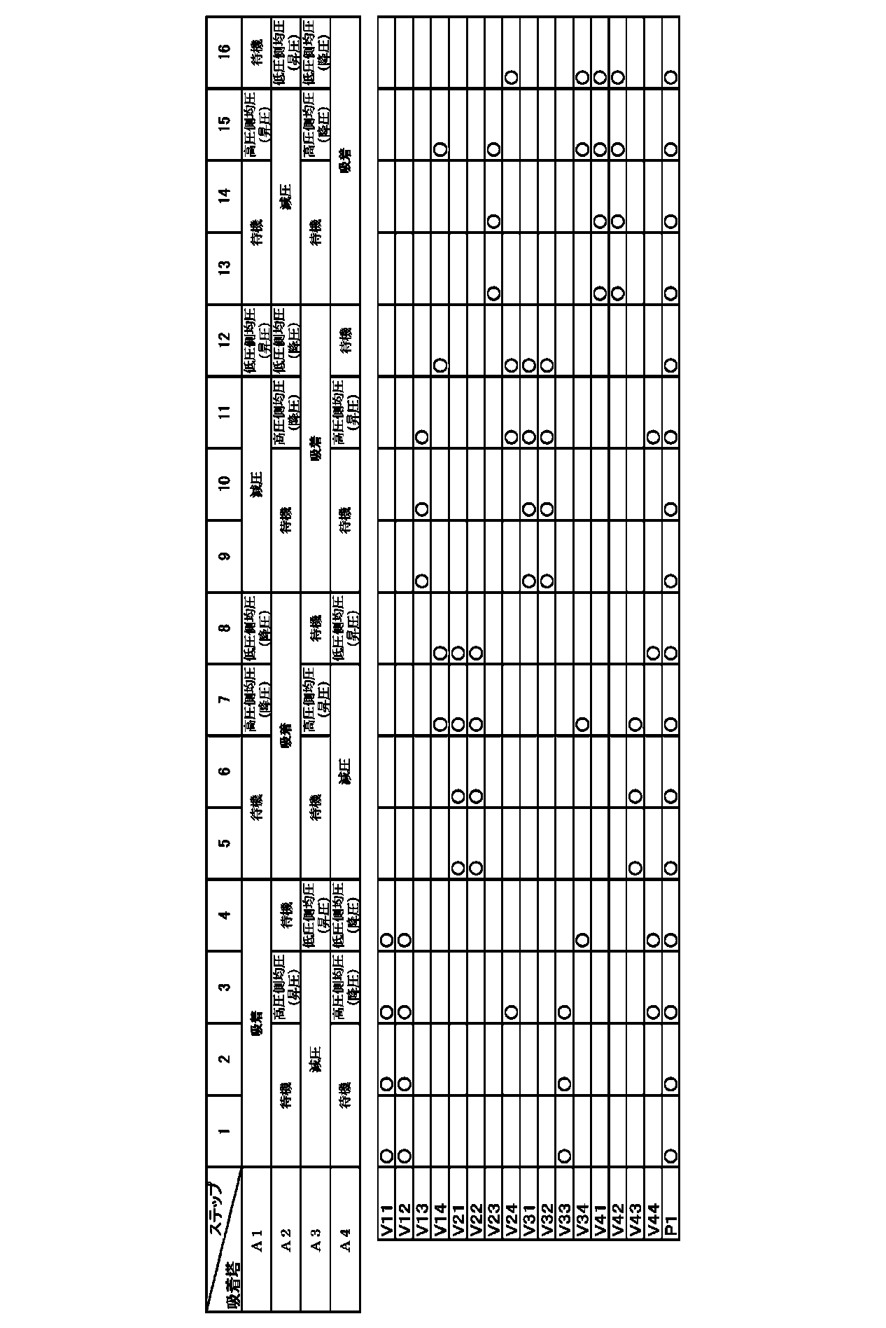
- the control device C controls the switching valves V11 to V44 and the supply pump P1, and in each of the adsorption towers A1 to A4, An adsorption step of receiving a supply of biogas from the lower part of the adsorption tower A1 and adsorbing a gas other than methane to the adsorbent A11 and releasing a non-adsorption gas mainly composed of methane from the upper part of the adsorption tower A1;
- the raw material gas is supplied to the adsorption tower A1 which finishes the adsorption process and performs the next pressure equalization (pressure reduction) process, and also to the adsorption tower A2 which finishes the pressure equalization (pressure increase) process and performs the adsorption process next.
- the raw material gas is supplied, and the non-adsorbed gas from the upper part of the adsorption tower A1 is transferred to the upper part of the adsorption tower A2 to bring the adsorption tower A1 into a slightly higher pressure state.
- Process, Waiting process The gas in the adsorption tower A1 in a slightly high pressure state is transferred to another adsorption tower A3 in a low pressure side intermediate pressure state lower than the adsorption tower A1, and the pressure in the adsorption tower A1 is changed to a high pressure side intermediate pressure state.
- High pressure side pressure equalization (pressure reduction) process A gas having a slightly increased adsorption gas concentration in the high pressure side intermediate pressure state adsorption tower A1 as compared with the high pressure side pressure equalization (pressure reduction) step is transferred to the other adsorption tower A4 in the low pressure state.
- a low-pressure side pressure equalization (step-down) step for setting the pressure in A1 to an intermediate pressure state on the low-pressure side; After the pressure in the tower is lowered by the low pressure side pressure equalization (pressure reduction) step, the adsorbent A11 is further reduced to a low pressure state, and the miscellaneous gas adsorbed on the adsorbent A11 is desorbed and recovered from the lower part of the adsorption tower A1.
- the other adsorption towers A2 to A4 perform the same operation by shifting the phase (time). However, since the description is duplicated, the detailed description is omitted with the description of Table 1.
- Table 1 o indicates that the corresponding switching valves V11 to V44 are in the open state or the corresponding pump P1 is in the operating state.
- Biogas is introduced into the first adsorption tower A1 from the source gas tank T1 as the source gas.
- the pressure in the first adsorption tower A1 is supplied from the raw material gas tank T1 through the switching valve V11 of the gas path L11 of the supply unit L1, while maintaining the pressure from a slightly high pressure state to a high pressure state as shown in FIG.
- Gas other than methane in the biogas is adsorbed on the adsorbent A11 of the first adsorption tower A1, and methane is discharged through the switching valve V12 of the gas path L12 of the recovery unit L2.
- the second adsorption tower A2 performs the ⁇ 1, 3> standby step and the ⁇ 2> high-pressure side pressure equalization (pressure increase) step.
- the ⁇ 3> low pressure side pressure equalization (pressure increase) step is performed after the ⁇ 1,2> pressure reduction step.
- a ⁇ 2> high pressure side pressure equalization (pressure reduction) step and a ⁇ 3> low pressure side pressure equalization (pressure reduction) step are performed.
- Adsorption equalization (pressure reduction) step In the first adsorption tower A1 that has finished the adsorption step, the adsorption equalization with the second adsorption tower A2 that finishes the high pressure side pressure equalization (pressure increase) step and then performs the adsorption step.
- a pressure (pressure reduction) step is performed. That is, in the first adsorption tower A1, the biogas is supplied from the raw material gas tank T1 via the switching valve V11 of the gas path L11 of the supply section L1, and in the second adsorption tower A2, the gas path L21 of the supply section L1.
- the non-adsorbed gas in the first adsorption tower A1 is passed through the switching valve V14 in the gas path L14 of the pressure equalizing unit L4. It has the structure which discharges
- the first adsorption tower A1 is pressure balanced with the second adsorption tower A2 in the intermediate pressure state on the high pressure side, and shifts from the high pressure state to a slightly higher pressure state.
- the first adsorption tower A1 is in a standby state, and while maintaining a time balance with the adsorption step that requires the longest time, a slightly high pressure state is maintained.
- the second adsorption tower A2 is performing the adsorption process
- the third adsorption tower A3 is also in the standby process
- the fourth adsorption tower A4 is continuing the decompression process.
- High pressure side pressure equalization (pressure reduction) step In the first adsorption tower A1 that has completed the adsorption pressure equalization (pressure reduction) step, the first adsorption tower A3 that performs the high pressure side pressure equalization (pressure increase) step is connected to the high pressure side.
- a pressure equalization (pressure reduction) step is performed. That is, the non-adsorbed gas in the tower is discharged via the switching valve V14 of the gas path L14 of the pressure equalizing section L4, and transferred to the third adsorption tower A3 via the switching valve V34 of the gas path L34 of the pressure equalizing section L4. It is the composition to do.
- the first adsorption tower A1 is pressure balanced with the third adsorption tower A3 in the intermediate pressure state on the low pressure side, and shifts from the slightly higher high pressure state to the intermediate pressure state on the high pressure side. .
- each on-off valve is operated to perform the adsorption process in the second adsorption tower A2, and the decompression process is performed in the fourth adsorption tower A4.
- Step down is performed. That is, the initial desorbed gas mainly composed of the non-adsorbed gas in the tower and the air from the adsorbent A11 is discharged via the switching valve V14 of the gas path L14 of the pressure equalizing part L4, and the gas in the pressure equalizing part L4 It has the structure which transfers to 4th adsorption tower A4 via the switching valve V44 of the path L44.
- the first adsorption tower A1 finishes the depressurization step and is in pressure equilibrium with the fourth adsorption tower A4 in the low pressure state, and the intermediate pressure state from the high pressure side to the low pressure side intermediate pressure state.
- each on-off valve is operated, the second adsorption tower A2 is performing the adsorption process, and the third adsorption tower A3 is performing the standby process.
- the first adsorption tower A1 that has reached the intermediate pressure state on the low pressure side is in a state in which a high concentration of miscellaneous gas is adsorbed to the adsorbent A11 in the tower,
- the high concentration adsorption target gas (miscellaneous gas) adsorbed on the adsorbent A11 is discharged. That is, the adsorption target gas is taken out via the switching valve V13 of the gas path L13 of the decompression unit L3.
- the first adsorption tower A1 shifts from the intermediate pressure state on the low pressure side to the low pressure state. Therefore, the pressure in the first adsorption tower A1 when performing this decompression step can be lowered, and the amount of non-adsorbed gas remaining in the first adsorption tower A1 can be reduced when performing the decompression step. Can do. That is, the gas amount of the non-adsorbed gas containing the gas to be purified that is discarded from the inside of the adsorption tower A1 in the depressurization step is very much left in the first adsorption tower A1 in the intermediate pressure state on the low pressure side. Only a small amount of non-adsorbed gas is present.
- each on-off valve etc. is operated, ⁇ 8> adsorption pressure equalization (pressure reduction) process between the second adsorption tower A2 and the third adsorption tower A3, ⁇ 9>
- a ⁇ 10> high pressure side pressure equalization (pressure reduction) process is performed.
- the process proceeds to the ⁇ 9, 10> adsorption step.
- the fourth adsorption tower A4 after the ⁇ 8, 9> standby step, the process proceeds to the ⁇ 10> high pressure side pressure equalization (pressure increase) step.
- Low pressure side pressure equalization (pressure increase) step In the first adsorption tower A1 in which the adsorbed miscellaneous gas is released in a low pressure state and the adsorbent A11 is regenerated, the first adsorption tower A2 and the second adsorption tower A2 are on the low pressure side.
- the pressure equalization (pressure increase) step By performing the pressure equalization (pressure increase) step, the pressure in the column is recovered and methane is released by the initial desorption gas from the adsorbent A21 discharged in the low pressure side pressure equalization (pressure decrease) step in the second adsorption tower A2. Accepts exhaust gas with increased concentration.
- the column gas discharged from the second adsorption tower A2 in the intermediate pressure state on the high pressure side is received via the switching valves V14 and V24.
- the first adsorption tower A1 recovers the pressure from the low pressure state to the intermediate pressure state on the low pressure side.
- the first adsorption tower A1 is in a standby state and the intermediate pressure state on the low pressure side is maintained.
- the ⁇ 12, 13> decompression process is performed in the second adsorption tower A2, and the third adsorption tower A3 shifts from the ⁇ 12> adsorption pressure equalization (pressure reduction) process to the ⁇ 13> standby process.
- the process proceeds to the ⁇ 13> adsorption process after the ⁇ 12> adsorption pressure equalization (pressure increase) process.
- High pressure side pressure equalization (pressure increase) step The first adsorption tower A1 that has recovered the pressure to the low pressure side intermediate pressure state finishes the adsorption pressure equalization (pressure decrease) step and performs the high pressure side pressure equalization (pressure decrease) step.
- a high pressure side pressure equalization (pressure increase) step With the third adsorption tower A3, the pressure in the tower is further recovered. That is, in the gas passages L14 and L34 of the pressure equalizing section L4, the gas in the tower discharged from the third adsorption tower A3 in a slightly high pressure state is received via the switching valves V14 and V34. Thereby, as shown in FIG. 2, the first adsorption tower A1 recovers the pressure from the low pressure side intermediate pressure state to the high pressure side intermediate pressure state.
- each on-off valve etc. is operated, the pressure reduction process is performed in 2nd adsorption tower A2, and the adsorption process is performed in 4th adsorption tower A4.
- 1st adsorption tower A1 will be in a standby state, and while maintaining the time balance with the adsorption process which requires the longest time, the intermediate pressure state of a high voltage
- the second adsorption tower A2 performs a low pressure side pressure equalization (pressure increase) process with the third adsorption tower A3, and the third adsorption tower A3 performs a corresponding low pressure side pressure equalization (pressure decrease) process. Is going.
- the fourth adsorption tower A4 continues the adsorption process.
- Example ⁇ As shown in the above embodiment, the following four adsorption towers A1 to A4 are prepared and filled with the following adsorbents A11 to A41, and the respective adsorption towers A1 to A4 are connected by piping as shown in FIG. A methane concentrator was prepared. The simulated biogas was supplied to this methane concentrator at 25.1 L / min, and the methane gas concentration operation shown in Table 1 and FIG. 2 was performed under the following operating conditions.
- Adsorbent When the pore size distribution measured by the molecular sieve carbon MP method is a pore size of 0.38 nm or more, the pore volume (V 0.38 ) at the pore size is about 0.05 cm 3 / g, Molecular sieve carbon having a pore volume (V 0.34 ) of 0.20 to 0.23 cm 3 / g at a pore diameter of 0.34 nm
- methane having a methane concentration of 98.1% by volume can be obtained as a product gas at 12.6 L / min, and the recovery rate ((the amount of methane in the product gas / the amount of methane in the raw material gas) ⁇ 100) is It was 82.9%.
- the recovery rate was 80.2% in the comparative example. In the example, it is 82.9%. Therefore, in the example, while maintaining extremely high purity gas concentration, the recovery rate can be improved by about 3% compared to the comparative example, and it is clear that a more efficient gas concentration method can be performed. Became.
- the first adsorption tower A1 performs the ⁇ 4> adsorption pressure equalization (pressure reduction) step
- the second adsorption tower A2 is brought into a raw material gas supply state by simultaneously supplying the raw material gas to both of the second adsorption tower A2 which finishes the process and performs the adsorption process next.
- the second adsorption tower which finishes the pressure equalization (pressure increase) process and then performs the adsorption process without supplying the raw material gas to the first adsorption tower A1 which finishes the adsorption process and then performs the pressure equalization (pressure decrease) process.
- the second adsorption tower A2 can be brought into the source gas supply state.
- the control device C controls the switching valves V11 to V44 and the supply pump P1, and in each of the adsorption towers A1 to A4, An adsorption step of receiving a supply of biogas from the lower part of the adsorption tower A1 and adsorbing a gas other than methane to the adsorbent A11 and releasing a non-adsorption gas mainly composed of methane from the upper part of the adsorption tower A1; For the adsorption tower A2 which finishes the pressure equalization (pressure increase) process and then performs the adsorption process without supplying the raw material gas to the adsorption tower A1 which finishes the adsorption process and then performs the pressure equalization (pressure reduction) process.
- the control device C controls the switching valves V11 to V44 and the supply pump P1, and in each of the adsorption towers A1 to A4, An adsorption step of receiving a supply of biogas from the lower part of the adsorption tower A1 and a
- An adsorption pressure equalization (step-down) step for transferring the non-adsorbed gas from the upper part of the adsorption tower A1 to the upper part of the adsorption tower A2 to bring the adsorption tower A1 into a slightly higher pressure state in the raw material gas supply state for supplying the raw material gas.
- Waiting process The gas in the adsorption tower A1 in a slightly high pressure state is transferred to another adsorption tower A3 in a low pressure side intermediate pressure state lower than the adsorption tower A1, and the pressure in the adsorption tower A1 is changed to a high pressure side intermediate pressure state.
- the fourth step and the sixteenth step are controlled as follows.
- Adsorption equalization (pressure reduction) step In the first adsorption tower A1 that performs the pressure equalization (pressure reduction) step after the adsorption step, the second adsorption performs the adsorption step after the high pressure side pressure equalization (pressure increase) step.
- An adsorption pressure equalization (pressure reduction) step is performed with the tower A2. That is, the first adsorption tower A1 does not receive the biogas from the raw material gas tank T1, and the second adsorption tower A2 receives the biogas from the raw material gas tank T1 via the switching valve V21 of the gas path L21 of the supply unit L1.
- the non-adsorbed gas in the first adsorption tower A1 is discharged via the switching valve V14 of the gas path L14 of the pressure equalizing section L4, and the switching valve of the gas path L24 of the pressure equalizing section L4 It becomes the structure transferred to 2nd adsorption tower A2 via V24.
- the first adsorption tower A1 is pressure balanced with the second adsorption tower A2 in the intermediate pressure state on the high pressure side, and shifts from the high pressure state to a slightly higher pressure state.
- each on-off valve etc. is operated, the standby process is performed in the third adsorption tower A3, and the decompression process is performed in the fourth adsorption tower A4.
- Adsorption equalization (pressure increase) step Next, in the first adsorption tower A1 which finishes the high pressure side pressure equalization (pressure increase) step and then performs the adsorption step, the adsorption step is completed and then the high pressure side pressure equalization (pressure decrease) step.
- An adsorption pressure equalization (pressure increase) step is performed with the fourth adsorption tower A4. That is, the fourth adsorption tower A4 receives no biogas from the raw material gas tank T1, and the first adsorption tower A1 receives the biogas from the raw material gas tank T1 via the switching valve V11 of the gas path L11 of the supply unit L1.
- the non-adsorbed gas in the fourth adsorption tower A4 is discharged via the switching valves V14, V44 of the gas passages L14, L44 of the pressure equalizing portion L4, and the gas passage L44 of the pressure equalizing portion L4 is switched. It is configured to transfer to the first adsorption tower A1 via the valve V44.
- the first adsorption tower A1 is in pressure equilibrium with the fourth adsorption tower A4 in the high pressure state, and shifts from the intermediate pressure state on the high pressure side to the slightly higher high pressure state.
- a standby process is performed in the second adsorption tower A2, and a decompression process is performed in the third adsorption tower A3.
- both examples were able to concentrate methane to a purity of about 98% by volume or more, whereas the recovery rate was 80.2% in the comparative example. In another embodiment, it is 81.7%. Therefore, in another example, while maintaining extremely high purity gas concentration, the recovery rate can be improved by about 2% with respect to the comparative example. In the case of the example (recovery rate is 82.9%). It was revealed that an efficient gas concentration method could be performed as in (1).
- each of the switching valves V11 to V34 and the supply pump P1 is controlled so that each of the adsorption towers A1 to A3
- the second adsorption tower A2 that finishes at least the pressure equalization (pressure increase) step and then performs the adsorption step is performed.
- Adsorption equalization which makes the said adsorption tower A1 a slightly high pressure state by supplying raw material gas and transferring the non-adsorption gas from the upper part of said 1st adsorption tower A1 to the upper part of the said 2nd adsorption tower A2.
- Step-down process,
- the second adsorption tower A2 is in the raw material gas supply state, but it does not matter whether the first adsorption tower A1 is in the raw material supply state (indicated by ⁇ in Table 4).
- a gas pressure equalization (step-down) step in which the gas in the adsorption tower A1 in a slightly higher pressure state is transferred to the other adsorption tower A3 in a lower pressure state than the adsorption tower A1 so that the pressure in the adsorption tower A1 is in an intermediate pressure state;
- the adsorbent A11 is further reduced to a low pressure state, and gas other than methane adsorbed on the adsorbent A11 is desorbed and recovered from the lower part of the adsorption tower A1.
- a decompression step A pressure equalization (pressure increase) step for receiving the gas in the adsorption tower A2 in the intermediate pressure state into the adsorption tower A1 in the low pressure state and setting the pressure in the adsorption tower A1 to the intermediate pressure state;
- the supply gas and the non-adsorption gas from the high-pressure adsorption tower A3 are supplied to bring the adsorption tower A1 into a slightly high pressure state (pressure increase).
- the operation is controlled in such a way as to perform in order. Further, the same operation can be performed with respect to the other adsorption towers A2 to A3 by shifting the phase (time).
- the pressure change in the first adsorption tower A1 is described as a high pressure state, a slightly higher high pressure state, an intermediate pressure state, and a low pressure state in order from the higher pressure. .
- supply stop pressure equalization step Only the pressure equalization step (hereinafter referred to as supply stop pressure equalization step) is performed between the first adsorption tower A1 and the second adsorption tower A2 without supplying the raw material gas to the adsorption tower A2. investigated.
- the control device C controls the switching valves V11 to V44 and the supply pump P1, and in each of the adsorption towers A1 to A4, An adsorption step of receiving a supply of biogas from the lower part of the adsorption tower A1 and adsorbing a gas other than methane to the adsorbent A11 and releasing a non-adsorption gas mainly composed of methane from the upper part of the adsorption tower A1; For the adsorption tower A2 which finishes the pressure equalization (pressure increase) process and then performs the adsorption process without supplying the raw material gas to the adsorption tower A1 which finishes the adsorption process and then performs the pressure equalization (pressure reduction) process.
- the control device C controls the switching valves V11 to V44 and the supply pump P1, and in each of the adsorption towers A1 to A4, An adsorption step of receiving a supply of biogas from the lower part of the adsorption tower A1 and a
- a non-adsorbed gas from the upper part of the adsorption tower A1 is transferred to the upper part of the adsorption tower A2 to bring the adsorption tower A1 into a slightly high pressure state.
- the gas in the adsorption tower A1 in a slightly high pressure state is transferred to another adsorption tower A3 in a low pressure side intermediate pressure state lower than the adsorption tower A1, and the pressure in the adsorption tower A1 is changed to a high pressure side intermediate pressure state.
- High pressure side pressure equalization (pressure reduction) process A gas having a slightly increased adsorption gas concentration in the high pressure side intermediate pressure state adsorption tower A1 as compared with the high pressure side pressure equalization (pressure reduction) step is transferred to the other adsorption tower A4 in the low pressure state.
- a low-pressure side pressure equalization (step-down) step for setting the pressure in A1 to an intermediate pressure state on the low-pressure side; After the pressure in the tower is lowered by the low pressure side pressure equalization (pressure reduction) step, the adsorbent A11 is further reduced to a low pressure state, and the miscellaneous gas adsorbed on the adsorbent A11 is desorbed and recovered from the lower part of the adsorption tower A1.
- a low pressure side pressure equalization (pressure increase) step for receiving the gas in the high pressure side intermediate pressure state adsorption tower A2 in the low pressure state adsorption tower A1 and setting the pressure in the adsorption tower A1 to the low pressure side intermediate pressure state; Waiting process, High pressure side pressure equalization (in which the gas in the other adsorption tower A3 in the slightly higher pressure state is received in the adsorption tower A1 in the intermediate pressure state on the low pressure side and the pressure in the adsorption tower A1 is changed to the intermediate pressure state on the high pressure side ( Step) Waiting process, Corresponding to the adsorption pressure equalization (pressure reduction) step, the supply stop pressure equalization (pressure increase) is performed by receiving the gas supply from the adsorption tower A4 in the high pressure state and changing the adsorption tower A1 from the intermediate pressure state on the high pressure side to a slightly high pressure state.
- Operation control is performed so that the steps are sequentially performed.
- the other adsorption towers A2 to A4 perform the same operation by shifting the phase (time). However, since the description is duplicated, the detailed description is omitted with the description of Table 5.
- the pressure change in the adsorption tower A1 is described as a high pressure state, a slightly high high pressure state, a high pressure side intermediate pressure state, a low pressure side intermediate pressure state, and a low pressure state in order from the highest pressure. Yes.
- ⁇ indicates that the corresponding switching valves V11 to V44 are in the open state or the corresponding supply pump P1 is in the operating state.
- the fourth step and the sixteenth step are controlled as follows.
- the second adsorption step performs the adsorption step after the high pressure side pressure equalization (pressure increase) step.
- a supply stop pressure equalization (pressure reduction) step is performed with the adsorption tower A2. That is, the first adsorption tower A1 does not receive the biogas from the raw material gas tank T1, and the second adsorption tower A2 does not receive the biogas from the raw material gas tank T1.
- the non-adsorbed gas in the first adsorption tower A1 is discharged via the switching valve V14 and transferred to the second adsorption tower A2 via the switching valve V24 of the gas path L24 of the pressure equalizing section L4.
- the first adsorption tower A1 is pressure balanced with the second adsorption tower A2 in the intermediate pressure state on the high pressure side, and shifts from the high pressure state to a slightly higher pressure state.
- each on-off valve etc. is operated, the standby process is performed in the third adsorption tower A3, and the decompression process is performed in the fourth adsorption tower A4.
- a supply stop pressure equalization (pressure increase) step is performed with the fourth adsorption tower A4 performing the step. That is, in the fourth adsorption tower A4, the biogas is not supplied from the raw material gas tank T1, but also in the first adsorption tower A1, the biogas is supplied from the raw material gas tank T1 via the switching valve V11 of the gas path L11 of the supply unit L1.
- the non-adsorbed gas in the fourth adsorption tower A4 is discharged via the switching valves V14, V44 of the gas paths L14, L44 of the pressure equalizing section L4, and the switching valve of the gas path L44 of the pressure equalizing section L4. It becomes the structure transferred to 1st adsorption tower A1 via V44.
- the first adsorption tower A1 is in pressure equilibrium with the fourth adsorption tower A4 in the high pressure state, and shifts from the intermediate pressure state on the high pressure side to the slightly higher high pressure state.
- a standby process is performed in the second adsorption tower A2, and a decompression process is performed in the third adsorption tower A3.
- the specific time cycle of each adsorption tower is ⁇ 1, 5, 9, 13> 131 seconds ⁇ 2, 6, 10, 14> 6 seconds ⁇ 3, 7, 11, 15> 6 seconds ⁇ 4, 8, 12, 16> 1 second adsorption end condition: adsorption start From 143 seconds, the balance with the embodiment is achieved.
- the gas concentration method of the present invention can be used for a gas concentrator for recovering a high purity gas at a high recovery rate.
- A1 to A4 Adsorption tower (first to fourth adsorption tower) A11 to A41: adsorbent C: controller L1: supply unit L2: recovery unit L3: pressure reducing unit L4: pressure equalizing unit L11 to L44: gas path P1: supply pump T1: source gas tanks V11 to V44: switching valve
Landscapes
- Chemical & Material Sciences (AREA)
- Oil, Petroleum & Natural Gas (AREA)
- Chemical Kinetics & Catalysis (AREA)
- Engineering & Computer Science (AREA)
- General Chemical & Material Sciences (AREA)
- Organic Chemistry (AREA)
- Analytical Chemistry (AREA)
- Separation Of Gases By Adsorption (AREA)
Abstract
Description
吸着対象ガスを吸着する吸着材を充填した吸着塔が3塔以上設けられ、
吸着塔それぞれについて、
吸着塔下部から吸着対象ガスを含有する原料ガスの供給を受けて、吸着材に吸着対象ガスを吸着するとともに、非吸着成分を主成分とする非吸着ガスを吸着塔上部から放出する吸着工程と、
吸着工程を終え、高圧状態にある吸着塔内のガスを、より低圧状態の他の吸着塔に移送して吸着塔内を中間圧状態にする均圧(降圧)工程と、
均圧(降圧)工程により塔内圧力が低下した後、さらに吸着材を低圧状態まで減圧して、吸着材に吸着された吸着対象ガスを脱着させて吸着塔下部から回収する減圧工程と、
減圧工程を終え、より高圧状態にある他の吸着塔内からガスを受け入れて吸着塔内を中間圧状態にする均圧(昇圧)工程と、
を順に繰り返すPSA(Pressure Swing Adsorption)サイクルを、3塔以上の吸着塔間で、時期をずらせて順次実行するガス濃縮方法に関する。
これにより、原料ガスとしての炭鉱ガスから、吸着材を用いて空気を分離し、メタンを濃縮して、当該濃縮されたメタンを燃料等として利用できるとされている。
なお、本発明では均圧工程を行う一対の吸着塔のうち、他の塔にガスを移送させて、内部を降圧させる吸着塔に対しては均圧(降圧)工程、他の塔からのガスを受け入れて、内部を昇圧させる吸着塔に対しては均圧(昇圧)工程というように、区別して記述するものとしている。
吸着対象ガスを吸着する吸着材を充填した吸着塔が3塔以上設けられ、
前記吸着塔それぞれについて、
吸着塔下部から吸着対象ガスを含有する原料ガスの供給を受けて、前記吸着材に吸着対象ガスを吸着するとともに、非吸着成分を主成分とする非吸着ガスを吸着塔上部から放出する吸着工程と、
吸着工程を終え、高圧状態にある吸着塔内のガスを、より低圧状態の他の吸着塔に移送して吸着塔内を中間圧状態にする均圧(降圧)工程と、
均圧(降圧)工程により塔内圧力が低下した後、さらに前記吸着材を低圧状態まで減圧して、前記吸着材に吸着された吸着対象ガスを脱着させて吸着塔下部から回収する減圧工程と、
減圧工程を終え、より高圧状態にある他の吸着塔内からガスを受け入れて吸着塔内を中間圧状態にする均圧(昇圧)工程と、
を順に繰り返すPSAサイクルを、前記3塔以上の吸着塔間で、時期をずらせて順次実行するガス濃縮方法であって、
吸着工程を終えた第一の吸着塔に対して均圧(降圧)工程を行う前に、少なくとも均圧(昇圧)工程を終えかつ次に吸着工程を行う第二の吸着塔に対して原料ガスを供給する原料ガス供給状態で、前記第一の吸着塔の上部からの非吸着ガスを当該第二の吸着塔の上部に移送することにより、前記第一の吸着塔において吸着均圧(降圧)工程を行うとともに前記第二の吸着塔において吸着均圧(昇圧)工程を行うステップを含む点にある。
前記原料ガス供給状態が、吸着工程を終えかつ次に均圧(降圧)工程を行う第一の吸着塔、および、均圧(昇圧)工程を終えかつ次に吸着工程を行う第二の吸着塔の両方に、原料ガスを同時に供給する状態である点にある。
前記原料ガス供給状態が、吸着工程を終えかつ次に均圧(降圧)工程を行う第一の吸着塔に原料ガスを供給せずに、均圧(昇圧)工程を終えかつ次に吸着工程を行う第二の吸着塔に対して原料ガスを供給する状態である点にある。
前記吸着塔が4塔以上設けられ、
前記中間圧状態として、吸着塔内圧力の異なる複数の圧力状態が設定され、
前記均圧(降圧)工程として、
高圧状態の吸着塔内のガスを、当該吸着塔より低圧の中間圧状態の他の吸着塔に移送して、吸着塔内の圧力を高圧側の中間圧状態とする高圧側均圧(降圧)工程と、
低圧状態より高圧の中間圧状態の吸着塔内のガスを、低圧状態の他の吸着塔に移送して、吸着塔内の圧力を低圧側の中間圧状態とする低圧側均圧(降圧)工程と、
を含み、
前記均圧(昇圧)工程は、
低圧状態の吸着塔内に、前記高圧側の中間圧状態の吸着塔内のガスを受け入れて、吸着塔内の圧力を低圧側の中間圧状態とする低圧側均圧(昇圧)工程と、
低圧側の中間圧状態の吸着塔内に、高圧状態の他の吸着塔内のガスを受け入れて、吸着塔内の圧力を高圧側の中間圧状態とする高圧側均圧(昇圧)工程と、
を含み、
前記均圧(降圧)工程を行う吸着塔から、前記均圧(昇圧)工程を行う吸着塔へ、吸着塔上部から吸着塔上部にわたってガスを移送するものとしてもよい。
本発明のガス濃縮方法に用いられるガス濃縮装置は、図1に示すように、吸着材A11~A41を充填した吸着塔A1~A4と、原料ガスタンクT1からバイオガス(原料ガスの一例)を供給するとともに吸着材A11~A41に吸着しなかったメタンを回収する供給部L1および回収部L2と、吸着材A11~A41に吸着したメタン以外の雑ガスを減圧回収する減圧部L3と、供給部L1、回収部L2、減圧部L3の運転を制御する制御装置Cを設けて構成してある。
吸着塔A1~A4は、それぞれ、吸着材A11~A41を充填してなる。また、原料ガスタンクT1から供給ポンプP1によりバイオガスを原料ガスとして供給するガス路L11~L41を各吸着塔A1~A4の下部に設けて、供給部L1を構成する。吸着塔A1~A4に供給されたバイオガスから主に窒素、二酸化炭素が吸着対象ガスとして吸着されて非吸着ガスとして濃縮されたメタンを放出するガス路L12~L42を、各吸着塔A1~A4の上部に設けて回収部L2を構成してある。このような構成により、供給部L1から吸着塔A1~A4にバイオガスを供給するとともに、吸着材A11~A41に吸着されなかった非吸着ガスを回収部L2に排出する。これにより、吸着材A11~A41に吸着対象ガスを吸着して非吸着ガスと分離可能に構成してある。また、前記吸着塔A1~A4には、吸着材A11~A41に吸着された吸着対象ガスを排出するガス路L13~L43を各吸着塔A1~A4の下部に設けて、減圧部L3を構成してある。この減圧部L3により、供給部L1から供給されたバイオガスのうち吸着材A11~A41に吸着され、濃縮後の高濃度の吸着対象ガスを取出し可能に構成する。減圧部L3は、吸着塔A1~A4からガス路L13~L43を介して吸着対象ガスを取り出す構成としてある。
さらに、各吸着塔A1~A4間を接続するガス路L14~L44を各吸着塔A1~A4の上部に接続して、吸着塔A1~A4の上部から吸着塔A1~A4の上部に吸着塔A1~A4内部のガスを他の吸着塔A1~A4に移送する均圧部L4を構成してある。
なお、各ガス路L11~L44には、切替弁V11~44を設けてあり、供給ポンプP1の動作により、各吸着塔A1~A4へのガスの供給、排出、停止の切替を、制御装置Cから一括して制御可能に構成してある。
制御装置Cは、表1に示すように、各切替弁V11~V44および供給ポンプP1を制御して、各吸着塔A1~A4において、吸着塔A1について、
吸着塔A1下部からバイオガスの供給を受けて、吸着材A11にメタン以外のガスを吸着するとともに、メタンを主成分とする非吸着ガスを吸着塔A1上部から放出する吸着工程、
吸着工程を終えかつ次に均圧(降圧)工程を行う吸着塔A1に対して原料ガスを供給するとともに、均圧(昇圧)工程を終えかつ次に吸着工程を行う吸着塔A2に対しても同時に原料ガスを供給する原料ガス供給状態で、吸着塔A1の上部からの非吸着ガスを当該吸着塔A2の上部に移送して、吸着塔A1をやや高い高圧状態とする吸着均圧(降圧)工程、
待機工程、
やや高い高圧状態の吸着塔A1内のガスを、当該吸着塔A1より低圧の低圧側の中間圧状態の他の吸着塔A3に移送して、吸着塔A1内の圧力を高圧側の中間圧状態とする高圧側均圧(降圧)工程、
高圧側の中間圧状態の吸着塔A1内の、高圧側均圧(降圧)工程に比べて吸着ガス濃度のやや高められたガスを、低圧状態の他の吸着塔A4に移送して、吸着塔A1内の圧力を低圧側の中間圧状態とする低圧側均圧(降圧)工程、
低圧側均圧(降圧)工程により塔内圧力が低下した後、さらに吸着材A11を低圧状態まで減圧して、吸着材A11に吸着された雑ガスを脱着させて吸着塔A1下部から回収する減圧工程、
低圧状態の吸着塔A1内に、高圧側の中間圧状態の吸着塔A2内のガスを受け入れて、吸着塔A1内の圧力を低圧側の中間圧状態とする低圧側均圧(昇圧)工程、
待機工程、
低圧側の中間圧状態の吸着塔A1内に、やや高い高圧状態の他の吸着塔A3内のガスを受け入れて、吸着塔A1内の圧力を高圧側の中間圧状態とする高圧側均圧(昇圧)工程、
待機工程、
吸着均圧(降圧)工程に対応して、原料ガスおよび高圧状態の吸着塔A4からの非吸着ガスの供給を受け、吸着塔A1をやや高い高圧状態とする吸着均圧(昇圧)工程、
を順に行うように運転制御する。また、他の吸着塔A2~A4についても位相(時期)をずらせて同様の動作を行うが、説明が重複するので表1の説明をもって詳細な説明を省略する。
表1中○は対応する切替弁V11~V44が開状態または、対応するポンプP1が作動状態であることを示す。

第一吸着塔A1に、原料ガスタンクT1よりバイオガスを原料ガスとして導入する。このとき第一吸着塔A1内の圧力は、図2に示すようにやや高い高圧状態から高圧状態に昇圧維持されつつ、供給部L1のガス路L11の切替弁V11を介して原料ガスタンクT1から供給されるバイオガス中のメタン以外のガスを第一吸着塔A1の吸着材A11に吸着させ、メタンを回収部L2のガス路L12の切替弁V12を介して排出する。
なお、本実施形態では、図2に示すように、第一吸着塔A1内の圧力変化を圧力の高い方から順に、高圧状態、やや高い高圧状態、高圧側の中間圧状態、低圧側の中間圧状態、低圧状態として説明している。
また、第三吸着塔A3では、<1、2>減圧工程の後、<3>低圧側均圧(昇圧)工程を行っている。
さらに、第四吸着塔A4では、<1>待機工程の後、<2>高圧側均圧(降圧)工程、<3>低圧側均圧(降圧)工程を行っている。
吸着工程を終えた第一吸着塔A1では、高圧側均圧(昇圧)工程を終え次に吸着工程を行う第二吸着塔A2との間で、吸着均圧(降圧)工程を行う。すなわち、第一吸着塔A1では、供給部L1のガス路L11の切替弁V11を介して原料ガスタンクT1からバイオガスの供給を受け、かつ、第二吸着塔A2では、供給部L1のガス路L21の切替弁V21を介して原料ガスタンクT1からバイオガスの供給を受ける原料ガス供給状態で、均圧部L4のガス路L14の切替弁V14を介して、第一吸着塔A1内の非吸着ガスを排出し、均圧部L4のガス路L24の切替弁V24を介して第二吸着塔A2に移送する構成となっている。これにより第一吸着塔A1は、図2に示すように、高圧側の中間圧状態の第二吸着塔A2と圧力平衡が行われ、高圧状態からやや高い高圧状態に移行する。
次に、第一吸着塔A1は待機状態となり、最も長時間を要する吸着工程との時間バランスを図るとともに、やや高い高圧状態が維持される。このとき、第二吸着塔A2は吸着工程を行っており、また、第三吸着塔A3も待機工程にあり、第四吸着塔A4は減圧工程を継続している。
吸着均圧(降圧)工程を終えた第一吸着塔A1では、高圧側均圧(昇圧)工程を行う第三吸着塔A3との間で、高圧側均圧(降圧)工程を行う。すなわち、均圧部L4のガス路L14の切替弁V14を介して、塔内の非吸着ガスを排出し、均圧部L4のガス路L34の切替弁V34を介して第三吸着塔A3に移送する構成となっている。これにより、第一吸着塔A1は、図2に示すように、低圧側の中間圧状態の第三吸着塔A3と圧力平衡が行われ、やや高い高圧状態から高圧側の中間圧状態に移行する。
次に、第一吸着塔A1は、減圧工程を終え低圧側均圧(昇圧)工程を行う第四吸着塔A4との間で、低圧側均圧(降圧)工程を行う。すなわち、均圧部L4のガス路L14の切替弁V14を介して、塔内の非吸着ガスおよび吸着材A11からの空気を主成分とする初期脱離ガスを排出し、均圧部L4のガス路L44の切替弁V44を介して第四吸着塔A4に移送する構成となっている。これにより、第一吸着塔A1は、図2に示すように、減圧工程を終えて低圧状態の第四吸着塔A4と圧力平衡が行われ、高圧側の中間圧状態から低圧側の中間圧状態に移行する。
低圧側の中間圧状態に達した第一吸着塔A1は、塔内の吸着材A11に高濃度の雑ガスを吸着している状態になっており、塔内を低圧側の中間圧状態から低圧状態にまで減圧する減圧工程を行うことにより、吸着材A11に吸着された高濃度の吸着対象ガス(雑ガス)を排出する。すなわち、減圧部L3のガス路L13の切替弁V13を介して吸着対象ガスを取り出す。これにより、第一吸着塔A1は、図2に示されるように、低圧側の中間圧状態から低圧状態に移行する。
したがって、この減圧工程を行う際の第一吸着塔A1内の圧力をより低くすることができ、減圧工程を行う際に、第一吸着塔A1内に残存する非吸着ガスの量を減少させることができる。すなわち、減圧工程において吸着塔A1の内部から廃棄される精製対象ガスを含有している非吸着ガスのガス量は、低圧側の中間圧状態において第一吸着塔A1内に残存している非常に少量の非吸着ガスのみとなる。このため、本実施形態では、減圧工程において、廃棄される非吸着ガス量は、均圧吸着工程およびその他の均圧工程を全く行わない場合に対して4分の1になる。これは、従来、均圧工程を1サイクルに四度(高圧側の均圧(昇圧)工程および均圧(降圧)工程、低圧側の均圧(昇圧)工程および均圧(降圧)工程を、それぞれ一度ずつ)行っていた場合には廃棄される非吸着ガス量が、均圧工程を全く行わない場合に対して3分の1であったのと比較して、大きく減少させることができており、非吸着ガスの回収率という観点から非常に有効な構成であることが理解できる。
また、第三吸着塔A3では、<8>吸着均圧(昇圧)工程の後、<9、10>吸着工程に移行している。
さらに、第四吸着塔A4では<8、9>待機工程の後、<10>高圧側均圧(昇圧)工程に移行する。
低圧状態となって、吸着した雑ガスを放出し、吸着材A11を再生された第一吸着塔A1では、第二吸着塔A2との間で低圧側均圧(昇圧)工程を行うことにより、塔内の圧力を回復するとともに、第二吸着塔A2における低圧側均圧(降圧)工程で排出された、吸着材A21からの初期脱離ガスによりメタン濃度の高められた排ガスを受け入れる。すなわち、均圧部L4のガス路L14、L24において、切替弁V14、V24を介して高圧側の中間圧状態の第二吸着塔A2から排出される塔内ガスを受け入れる。これにより第一吸着塔A1は、図2に示すように、低圧状態から低圧側の中間圧状態にまで圧力を回復する。
次に第一吸着塔A1は待機状態になるとともに、低圧側の中間圧状態が維持される。
なお、この時、第二吸着塔A2では<12、13>減圧工程を行い、第三吸着塔A3では、<12>吸着均圧(降圧)工程から<13>待機工程に移行し、第四吸着塔A4では、<12>吸着均圧(昇圧)工程ののち、<13>吸着工程に移行する。
低圧側の中間圧状態にまで圧力を回復した第一吸着塔A1は、吸着均圧(降圧)工程を終えて高圧側均圧(降圧)工程を行う第三吸着塔A3との間で高圧側均圧(昇圧)工程を行うことにより、さらに塔内の圧力の回復を図る。すなわち、均圧部L4のガス路L14、L34において、切替弁V14、V34を介して、やや高い高圧状態の第三吸着塔A3から排出される塔内ガスを受け入れる。これにより第一吸着塔A1は、図2に示すように、低圧側の中間圧状態から高圧側の中間圧状態にまで圧力を回復する。
次に、第一吸着塔A1は待機状態となり、最も長時間を要する吸着工程との時間バランスを図るとともに、高圧側の中間圧状態が維持される。このとき、第二吸着塔A2は第三吸着塔A3との間で低圧側均圧(昇圧)工程を行っており、また、第三吸着塔A3は対応する低圧側均圧(降圧)工程を行っている。また、第四吸着塔A4は吸着工程を継続している。
次に、第一吸着塔A1は、吸着工程を終えかつ均圧(降圧)工程を行う前の第四吸着塔A4との間で、吸着均圧(昇圧)工程を行う。すなわち、第一吸着塔A1では、供給部L1のガス路L11の切替弁V11を介して原料ガスタンクT1からバイオガスの供給を受け、かつ、第四吸着塔A4では、供給部L1のガス路L41の切替弁V41を介して原料ガスタンクT1からバイオガスの供給を受ける原料ガス供給状態で、第四吸着塔A4からの非吸着ガスを均圧部L4のガス路L14、L44の切替弁V14、V44を介して第一吸着塔A1に受け入れる吸着均圧(昇圧)工程を行う。この時、第二吸着塔A2では待機工程、第三吸着塔A3では減圧工程を行う。これにより、第一吸着塔A1は、図2に示すように、高圧側の中間圧状態からやや高い高圧状態にまで圧力を回復する。
<1、5、9、13> 132秒
<2、6、10、14> 6秒
<3、7、11、15> 6秒
<4、8、12、16> 1秒
の時間バランスで各ステップを進行している。
上記実施形態に示すように、下記吸着塔A1~A4を4本用意し、その内部に下記吸着材A11~A41を充填して、それぞれの吸着塔A1~A4を図1に示すように配管接続したメタン濃縮装置を用意した。このメタン濃縮装置に、模擬バイオガスを25.1L/分で供給し、下記運転条件にて、表1、図2のメタンガスの濃縮運転を行った。
:4本
MP法によって細孔分布を測定した場合の細孔径分布が、細孔径0.38nm以上において、その細孔径における細孔容積(V0.38)が0.05cm3/g程度、細孔径0.34nmにおける細孔容積(V0.34)が0.20~0.23cm3/gであるモレキュラーシーブカーボン
:二酸化炭素 40%
:窒素 0.6%
温度:55℃
流速:25.1L/分
ガス吸着圧力(ゲージ圧力): 0.75MPa
ガス脱着圧力(ゲージ圧力): 0.1kPa
吸着工程の終了条件:吸着工程開始より145秒経過時
本発明のメタン濃縮方法の性能を評価するために、吸着均圧(昇圧)工程、吸着均圧(降圧)工程を行わないPSAタイムサイクルを用いてガス濃縮運転を行った。具体的には図1のガス濃縮装置を用いて表2に示すタイムサイクルでメタン濃縮運転を行った。なお、表2において、表1と同じ工程名を用いた工程は実施例と同様であるので、説明を省略するが、吸着均圧(昇圧)工程に代えて、吸着工程を行っており、吸着均圧(降圧)工程に代えて待機工程を行っている。
<1+2、5+6、9+10、13+14> 142秒
<3、7、11、15> 6秒
<4、8、12、16> 6秒
吸着終了条件:吸着開始から154秒
として、実施例との均衡を図っている。
上述の実施形態では、
前記第一吸着塔A1が<4>吸着均圧(降圧)工程を行うステップにおいて、吸着工程を終えかつ次に均圧(降圧)工程を行う第一の吸着塔A1、および、均圧(昇圧)工程を終えかつ次に吸着工程を行う第二の吸着塔A2の両方に、原料ガスを同時に供給することにより、前記第二の吸着塔A2を原料ガス供給状態としたが、
吸着工程を終えかつ次に均圧(降圧)工程を行う第一の吸着塔A1に原料ガスを供給せずに、均圧(昇圧)工程を終えかつ次に吸着工程を行う第二の吸着塔A2に対して原料ガスを供給することにより、前記第二の吸着塔A2を原料ガス供給状態とすることもできる。
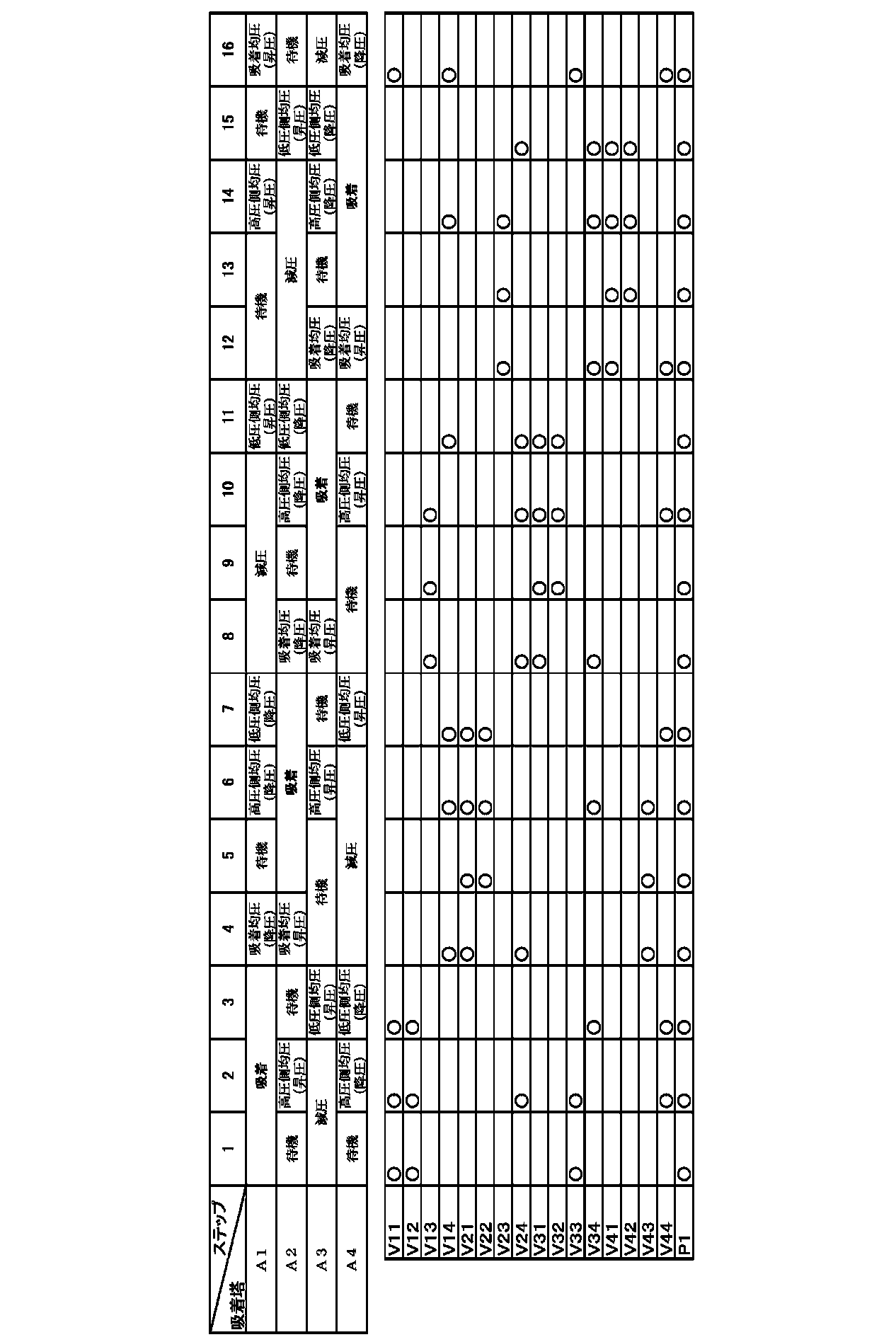
制御装置Cは、表3に示すように、各切替弁V11~V44および供給ポンプP1を制御して、各吸着塔A1~A4において、吸着塔A1について、
吸着塔A1下部からバイオガスの供給を受けて、吸着材A11にメタン以外のガスを吸着するとともに、メタンを主成分とする非吸着ガスを吸着塔A1上部から放出する吸着工程、
吸着工程を終えかつ次に均圧(降圧)工程を行う吸着塔A1に対して原料ガスを供給せずに、均圧(昇圧)工程を終えかつ次に吸着工程を行う吸着塔A2に対して原料ガスを供給する原料ガス供給状態で、吸着塔A1の上部からの非吸着ガスを当該吸着塔A2の上部に移送して、吸着塔A1をやや高い高圧状態とする吸着均圧(降圧)工程、
待機工程、
やや高い高圧状態の吸着塔A1内のガスを、当該吸着塔A1より低圧の低圧側の中間圧状態の他の吸着塔A3に移送して、吸着塔A1内の圧力を高圧側の中間圧状態とする高圧側均圧(降圧)工程、
高圧側の中間圧状態の吸着塔A1内の、高圧側均圧(降圧)工程に比べて吸着ガス濃度のやや高められたガスを、低圧状態の他の吸着塔A4に移送して、吸着塔A1内の圧力を低圧側の中間圧状態とする低圧側均圧(降圧)工程、
低圧側均圧(降圧)工程により塔内圧力が低下した後、さらに吸着材A11を低圧状態まで減圧して、吸着材A11に吸着された雑ガスを脱着させて吸着塔A1下部から回収する減圧工程、
低圧状態の吸着塔A1内に、高圧側の中間圧状態の吸着塔A2内のガスを受け入れて、吸着塔A1内の圧力を低圧側の中間圧状態とする低圧側均圧(昇圧)工程、
待機工程、
低圧側の中間圧状態の吸着塔A1内に、やや高い高圧状態の他の吸着塔A3内のガスを受け入れて、吸着塔A1内の圧力を高圧側の中間圧状態とする高圧側均圧(昇圧)工程、
待機工程、
吸着均圧(降圧)工程に対応して、原料ガスおよび高圧状態の吸着塔A4からの非吸着ガスの供給を受け、吸着塔A1を高圧側の中間圧状態からやや高い高圧状態とする吸着均圧(昇圧)工程、
を順に行うように運転制御する。また、他の吸着塔A2~A4についても位相(時期)をずらせて同様の動作を行うが、説明が重複するので表3の説明をもって詳細な説明を省略する。
表3中○は対応する切替弁V11~V44が開状態または、対応する供給ポンプP1が作動状態であることを示す。
吸着工程を終え次に均圧(降圧)工程を行う第一吸着塔A1では、高圧側均圧(昇圧)工程を終え次に吸着工程を行う第二吸着塔A2との間で、吸着均圧(降圧)工程を行う。すなわち、第一吸着塔A1では原料ガスタンクT1からのバイオガスの供給を受けずに、第二吸着塔A2では供給部L1のガス路L21の切替弁V21を介して原料ガスタンクT1からのバイオガスの供給を受ける原料ガス供給状態で、均圧部L4のガス路L14の切替弁V14を介して、第一吸着塔A1内の非吸着ガスを排出し、均圧部L4のガス路L24の切替弁V24を介して第二吸着塔A2に移送する構成となっている。これにより第一吸着塔A1は、図2に示すように、高圧側の中間圧状態の第二吸着塔A2と圧力平衡が行われ、高圧状態からやや高い高圧状態に移行する。
次に、高圧側均圧(昇圧)工程を終え次に吸着工程を行う第一吸着塔A1では、吸着工程を終え次に高圧側均圧(降圧)工程を行う第四吸着塔A4との間で、吸着均圧(昇圧)工程を行う。すなわち、第四吸着塔A4では原料ガスタンクT1からのバイオガスの供給を受けずに、第一吸着塔A1では供給部L1のガス路L11の切替弁V11を介して原料ガスタンクT1からバイオガスを受け入れる原料ガス供給状態で、均圧部L4のガス路L14、L44の切替弁V14、V44を介して、第四吸着塔A4内の非吸着ガスを排出し、均圧部L4のガス路L44の切替弁V44を介して第一吸着塔A1に移送する構成となっている。これにより第一吸着塔A1は、図2に示すように、高圧状態の第四吸着塔A4と圧力平衡が行われ、高圧側の中間圧状態からやや高い高圧状態に移行する。この時第二吸着塔A2では待機工程、第三吸着塔A3では減圧工程を行う。
このタイムサイクルを行って、実施例と同様にガス濃縮を行ったところ、製品ガスとしてメタン濃度98.2体積%のメタンを12.3L/分で得ることができ、回収率は81.7%であった。
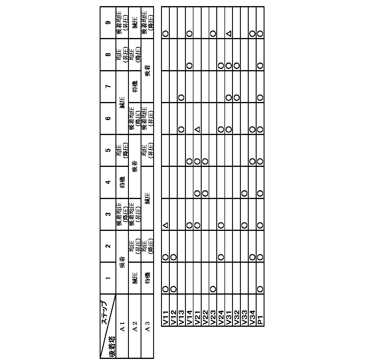
上述の実施形態では、いずれも吸着塔を4塔用いた例を用いて本発明を説明したが、吸着塔を3塔用いた場合(図3)であっても、同様に本願のガス濃縮方法を実施することができる。なお、図3について、図1の構成と共通する構成、機能を有する部分については、同様の符号を付することによって、詳細な説明は省略する。また、5塔以上用いた場合であっても、同様に本願のガス濃縮方法を実施することができるが、3塔、4塔の構成例に基づき自明であるので説明は省略する。
吸着塔A1下部から原料ガスの供給を受けて、前記吸着材A11にメタン以外のガスを吸着するとともに、メタンを主成分とする非吸着ガスを吸着塔A1上部から放出する吸着工程、
吸着工程を終えた第一の吸着塔A1に対して均圧(降圧)工程を行う前に、少なくとも均圧(昇圧)工程を終えかつ次に吸着工程を行う第二の吸着塔A2に対して原料ガスを供給し、前記第一の吸着塔A1の上部からの非吸着ガスを当該第二の吸着塔A2の上部に移送することにより、前記吸着塔A1をやや高い高圧状態とする吸着均圧(降圧)工程、
ここで、第二の吸着塔A2は原料ガス供給状態であるが、第一の吸着塔A1が原料供給状態かどうかについては、いずれでも構わない(表4中△で示す)。
待機工程、
やや高い高圧状態の吸着塔A1内のガスを、当該吸着塔A1より低圧状態の他の吸着塔A3に移送して、吸着塔A1内の圧力を中間圧状態とする均圧(降圧)工程、
均圧(降圧)工程により塔内圧力が低下した後、さらに前記吸着材A11を低圧状態まで減圧して、前記吸着材A11に吸着されたメタン以外のガスを脱着させて吸着塔A1下部から回収する減圧工程、
低圧状態の吸着塔A1内に、前記中間圧状態の吸着塔A2内のガスを受け入れて、吸着塔A1内の圧力を中間圧状態とする均圧(昇圧)工程、
吸着塔A3の吸着均圧(降圧)工程に対応して、原料ガスおよび高圧状態の吸着塔A3からの非吸着ガスの供給を受け、吸着塔A1をやや高い高圧状態とする吸着均圧(昇圧)工程、
を順に行うように運転制御する。また、他の吸着塔A2~A3についても位相(時期)をずらせて同様の動作を行うことができる。
なお、本実施形態では、図4に示すように、第一吸着塔A1内の圧力変化を圧力の高い方から順に、高圧状態、やや高い高圧状態、中間圧状態、低圧状態として説明している。
上述の実施形態における吸着均圧工程に代え、
吸着工程を終えかつ次に均圧(降圧)工程を行う第一の吸着塔A1に原料ガスを供給せずに、かつ、均圧(昇圧)工程を終えかつ次に吸着工程を行う第二の吸着塔A2に対して原料ガスを供給せずに、第一の吸着塔A1と第二の吸着塔A2との間で均圧工程(以下供給停止均圧工程と呼ぶ)のみを行った場合について検討した。
制御装置Cは、表5に示すように、各切替弁V11~V44および供給ポンプP1を制御して、各吸着塔A1~A4において、吸着塔A1について、
吸着塔A1下部からバイオガスの供給を受けて、吸着材A11にメタン以外のガスを吸着するとともに、メタンを主成分とする非吸着ガスを吸着塔A1上部から放出する吸着工程、
吸着工程を終えかつ次に均圧(降圧)工程を行う吸着塔A1に対して原料ガスを供給せずに、均圧(昇圧)工程を終えかつ次に吸着工程を行う吸着塔A2に対しても原料ガスを供給しない状態で、吸着塔A1の上部からの非吸着ガスを当該吸着塔A2の上部に移送して、吸着塔A1をやや高い高圧状態とする供給停止均圧(降圧)工程、
待機工程、
やや高い高圧状態の吸着塔A1内のガスを、当該吸着塔A1より低圧の低圧側の中間圧状態の他の吸着塔A3に移送して、吸着塔A1内の圧力を高圧側の中間圧状態とする高圧側均圧(降圧)工程、
高圧側の中間圧状態の吸着塔A1内の、高圧側均圧(降圧)工程に比べて吸着ガス濃度のやや高められたガスを、低圧状態の他の吸着塔A4に移送して、吸着塔A1内の圧力を低圧側の中間圧状態とする低圧側均圧(降圧)工程、
低圧側均圧(降圧)工程により塔内圧力が低下した後、さらに吸着材A11を低圧状態まで減圧して、吸着材A11に吸着された雑ガスを脱着させて吸着塔A1下部から回収する減圧工程、
低圧状態の吸着塔A1内に、高圧側の中間圧状態の吸着塔A2内のガスを受け入れて、吸着塔A1内の圧力を低圧側の中間圧状態とする低圧側均圧(昇圧)工程、
待機工程、
低圧側の中間圧状態の吸着塔A1内に、やや高い高圧状態の他の吸着塔A3内のガスを受け入れて、吸着塔A1内の圧力を高圧側の中間圧状態とする高圧側均圧(昇圧)工程、
待機工程、
吸着均圧(降圧)工程に対応して、高圧状態の吸着塔A4からのガスの供給を受け、吸着塔A1を高圧側の中間圧状態からやや高い高圧状態とする供給停止均圧(昇圧)工程、を順に行うように運転制御する。また、他の吸着塔A2~A4についても位相(時期)をずらせて同様の動作を行うが、説明が重複するので表5の説明をもって詳細な説明を省略する。
なお、本参考形態では、吸着塔A1内の圧力変化を圧力の高い方から順に、高圧状態、やや高い高圧状態、高圧側の中間圧状態、低圧側の中間圧状態、低圧状態として説明している。
表5中○は対応する切替弁V11~V44が開状態または、対応する供給ポンプP1が作動状態であることを示す。

吸着工程を終え次に均圧(降圧)工程を行う第一吸着塔A1では、高圧側均圧(昇圧)工程を終え次に吸着工程を行う第二吸着塔A2との間で、供給停止均圧(降圧)工程を行う。すなわち、第一吸着塔A1では原料ガスタンクT1からのバイオガスの供給を受けずに、第二吸着塔A2においても原料ガスタンクT1からバイオガスを受け入れない状態で、均圧部L4のガス路L14の切替弁V14を介して、第一吸着塔A1内の非吸着ガスを排出し、均圧部L4のガス路L24の切替弁V24を介して第二吸着塔A2に移送する構成となっている。これにより第一吸着塔A1は、図2に示すように、高圧側の中間圧状態の第二吸着塔A2と圧力平衡が行われ、高圧状態からやや高い高圧状態に移行する。
次に、高圧側均圧(昇圧)工程を終え次に吸着工程を行う第一吸着塔A1では、吸着工程を終え次に高圧側均圧(降圧)工程を行う第四吸着塔A4との間で、供給停止均圧(昇圧)工程を行う。すなわち、第四吸着塔A4では原料ガスタンクT1からのバイオガスの供給を受けずに、第一吸着塔A1においても供給部L1のガス路L11の切替弁V11を介して原料ガスタンクT1からバイオガスを受け入れない状態で、均圧部L4のガス路L14、L44の切替弁V14、V44を介して、第四吸着塔A4内の非吸着ガスを排出し、均圧部L4のガス路L44の切替弁V44を介して第一吸着塔A1に移送する構成となっている。これにより第一吸着塔A1は、図2に示すように、高圧状態の第四吸着塔A4と圧力平衡が行われ、高圧側の中間圧状態からやや高い高圧状態に移行する。この時第二吸着塔A2では待機工程、第三吸着塔A3では減圧工程を行う。
このタイムサイクルを行って、ガス濃縮を行ったところ、製品ガスとしてメタン濃度98.3体積%のメタンを12.3L/分で得ることができ、回収率は80.9%であった。
<1、5、9、13> 131秒
<2、6、10、14> 6秒
<3、7、11、15> 6秒
<4、8、12、16> 1秒
吸着終了条件:吸着開始から143秒
として、実施例との均衡を図っている。
A11~A41:吸着材
C :制御装置
L1 :供給部
L2 :回収部
L3 :減圧部
L4 :均圧部
L11~L44:ガス路
P1 :供給ポンプ
T1 :原料ガスタンク
V11~V44:切替弁
Claims (6)
- 吸着対象ガスを吸着する吸着材を充填した吸着塔が3塔以上設けられ、
前記吸着塔それぞれについて、
吸着塔下部から吸着対象ガスを含有する原料ガスの供給を受けて、前記吸着材に吸着対象ガスを吸着するとともに、非吸着成分を主成分とする非吸着ガスを吸着塔上部から放出する吸着工程と、
吸着工程を終え、高圧状態にある吸着塔内のガスを、より低圧状態の他の吸着塔に移送して吸着塔内を中間圧状態にする均圧(降圧)工程と、
均圧(降圧)工程により塔内圧力が低下した後、さらに前記吸着材を低圧状態まで減圧して、前記吸着材に吸着された吸着対象ガスを脱着させて吸着塔下部から回収する減圧工程と、
減圧工程を終え、より高圧状態にある他の吸着塔内からガスを受け入れて吸着塔内を中間圧状態にする均圧(昇圧)工程と、
を順に繰り返すPSAサイクルを、前記3塔以上の吸着塔間で、時期をずらせて順次実行するガス濃縮方法であって、
吸着工程を終えた第一の吸着塔に対して均圧(降圧)工程を行う前に、少なくとも均圧(昇圧)工程を終えかつ次に吸着工程を行う第二の吸着塔に対して原料ガスを供給する原料ガス供給状態で、前記第一の吸着塔の上部からの非吸着ガスを当該第二の吸着塔の上部に移送することにより、前記第一の吸着塔において吸着均圧(降圧)工程を行うとともに前記第二の吸着塔において吸着均圧(昇圧)工程を行うステップを含む
ガス濃縮方法。 - 前記原料ガス供給状態が、吸着工程を終えかつ次に均圧(降圧)工程を行う第一の吸着塔、および、均圧(昇圧)工程を終えかつ次に吸着工程を行う第二の吸着塔の両方に、原料ガスを同時に供給する状態である請求項1に記載のガス濃縮方法。
- 前記原料ガス供給状態が、吸着工程を終えかつ次に均圧(降圧)工程を行う第一の吸着塔に原料ガスを供給せずに、均圧(昇圧)工程を終えかつ次に吸着工程を行う第二の吸着塔に対して原料ガスを供給する状態である請求項1に記載のガス濃縮方法。
- 前記吸着塔が4塔以上設けられ、
前記中間圧状態として、吸着塔内圧力の異なる複数の圧力状態が設定され、
前記均圧(降圧)工程として、
高圧状態の吸着塔内のガスを、当該吸着塔より低圧の中間圧状態の他の吸着塔に移送して、吸着塔内の圧力を高圧側の中間圧状態とする高圧側均圧(降圧)工程と、
低圧状態より高圧の中間圧状態の吸着塔内のガスを、低圧状態の他の吸着塔に移送して、吸着塔内の圧力を低圧側の中間圧状態とする低圧側均圧(降圧)工程と、
を含み、
前記均圧(昇圧)工程は、
低圧状態の吸着塔内に、前記高圧側の中間圧状態の吸着塔内のガスを受け入れて、吸着塔内の圧力を低圧側の中間圧状態とする低圧側均圧(昇圧)工程と、
低圧側の中間圧状態の吸着塔内に、高圧状態の他の吸着塔内のガスを受け入れて、吸着塔内の圧力を高圧側の中間圧状態とする高圧側均圧(昇圧)工程と、
を含み、
前記均圧(降圧)工程を行う吸着塔から、前記均圧(昇圧)工程を行う吸着塔へ、吸着塔上部から吸着塔上部にわたってガスを移送する請求項1~3のいずれか一項に記載のガス濃縮方法。 - 前記原料ガスが、炭鉱ガス、バイオガス、改質ガス、天然ガスから選ばれる一種のガスを主成分とするものであり、精製対象ガスがメタンである請求項1~4のいずれか一項に記載のガス濃縮方法。
- 前記吸着材は、活性炭、モレキュラーシーブカーボン、ゼオライト、多孔性の金属錯体から選択される少なくとも一種を主成分として含有する請求項1~5のいずれか一項に記載のガス濃縮方法。
Priority Applications (8)
| Application Number | Priority Date | Filing Date | Title |
|---|---|---|---|
| PL421712A PL239373B1 (pl) | 2014-06-27 | 2015-06-26 | Sposób koncentracji gazu |
| JP2016529680A JP6351721B2 (ja) | 2014-06-27 | 2015-06-26 | ガス濃縮方法 |
| AU2015281014A AU2015281014B2 (en) | 2014-06-27 | 2015-06-26 | Gas concentration method |
| SG11201610842RA SG11201610842RA (en) | 2014-06-27 | 2015-06-26 | Gas-condensing method |
| US15/321,814 US10124287B2 (en) | 2014-06-27 | 2015-06-26 | Gas concentration method |
| MYPI2016704762A MY181837A (en) | 2014-06-27 | 2015-06-26 | Gas concentration method |
| CN201580034245.9A CN106413851B (zh) | 2014-06-27 | 2015-06-26 | 气体浓缩方法 |
| PH12016502584A PH12016502584B1 (en) | 2014-06-27 | 2016-12-22 | Gas concentration method |
Applications Claiming Priority (2)
| Application Number | Priority Date | Filing Date | Title |
|---|---|---|---|
| JP2014133150 | 2014-06-27 | ||
| JP2014-133150 | 2014-06-27 |
Publications (1)
| Publication Number | Publication Date |
|---|---|
| WO2015199227A1 true WO2015199227A1 (ja) | 2015-12-30 |
Family
ID=54938304
Family Applications (1)
| Application Number | Title | Priority Date | Filing Date |
|---|---|---|---|
| PCT/JP2015/068534 Ceased WO2015199227A1 (ja) | 2014-06-27 | 2015-06-26 | ガス濃縮方法 |
Country Status (9)
| Country | Link |
|---|---|
| US (1) | US10124287B2 (ja) |
| JP (1) | JP6351721B2 (ja) |
| CN (1) | CN106413851B (ja) |
| AU (1) | AU2015281014B2 (ja) |
| MY (1) | MY181837A (ja) |
| PH (1) | PH12016502584B1 (ja) |
| PL (1) | PL239373B1 (ja) |
| SG (1) | SG11201610842RA (ja) |
| WO (1) | WO2015199227A1 (ja) |
Cited By (4)
| Publication number | Priority date | Publication date | Assignee | Title |
|---|---|---|---|---|
| PL427936A1 (pl) * | 2016-03-31 | 2019-04-23 | Osaka Gas Co Ltd | Urządzenie do wytwarzania gazu metodą adsorpcji zmiennociśnieniowej |
| EP3613492A1 (en) | 2018-08-14 | 2020-02-26 | Air Products And Chemicals, Inc. | Multi-bed rapid cycle kinetic psa |
| JPWO2020105242A1 (ja) * | 2018-11-19 | 2021-09-30 | 住友精化株式会社 | ガス分離装置及びガス分離方法 |
| JP2024062420A (ja) * | 2022-03-04 | 2024-05-09 | 日本碍子株式会社 | ガス吸着システムの運転方法 |
Families Citing this family (2)
| Publication number | Priority date | Publication date | Assignee | Title |
|---|---|---|---|---|
| US10835856B2 (en) | 2018-08-14 | 2020-11-17 | Air Products And Chemicals, Inc. | Carbon molecular sieve adsorbent |
| US10730006B2 (en) | 2018-08-14 | 2020-08-04 | Air Products And Chemicals, Inc. | Port separation for rotary bed PSA |
Citations (6)
| Publication number | Priority date | Publication date | Assignee | Title |
|---|---|---|---|---|
| JP2001187309A (ja) * | 1999-11-03 | 2001-07-10 | Praxair Technol Inc | 水素製造のための圧力変動吸着法 |
| JP2007537867A (ja) * | 2004-05-19 | 2007-12-27 | プラクスエア・テクノロジー・インコーポレイテッド | 連続フィード3床圧力スイング吸着システム |
| JP2008246403A (ja) * | 2007-03-30 | 2008-10-16 | Osaka Gas Co Ltd | ガス製造装置 |
| JP2012503543A (ja) * | 2008-09-26 | 2012-02-09 | プラクスエア・テクノロジー・インコーポレイテッド | Noxとso2吸着剤/触媒として活性炭を用いる二酸化炭素精製 |
| JP2013528486A (ja) * | 2010-05-05 | 2013-07-11 | ラムス テクノロジー インコーポレイテッド | 吸着ベッドのステージ化されたブローダウン |
| JP2013155076A (ja) * | 2012-01-30 | 2013-08-15 | Taiyo Nippon Sanso Corp | 窒素富化ガス製造方法、ガス分離方法および窒素富化ガス製造装置 |
Family Cites Families (10)
| Publication number | Priority date | Publication date | Assignee | Title |
|---|---|---|---|---|
| JPS58198591A (ja) | 1982-05-14 | 1983-11-18 | Shigeji Honda | メタン濃縮法 |
| US4756723A (en) * | 1987-03-04 | 1988-07-12 | Air Products And Chemicals, Inc. | Preparation of high purity oxygen |
| US6007606A (en) * | 1997-12-09 | 1999-12-28 | Praxair Technology, Inc. | PSA process and system |
| US7396387B2 (en) * | 2005-11-01 | 2008-07-08 | Praxair Technology, Inc. | Pressure swing adsorption process for large capacity oxygen production |
| CN100444933C (zh) * | 2006-03-22 | 2008-12-24 | 四川省达科特化工科技有限公司 | 一种变压吸附法回收低分压气体的方法 |
| US7763100B2 (en) * | 2006-07-06 | 2010-07-27 | Praxair Technology, Inc. | Vacuum pressure swing adsorption process and enhanced oxygen recovery |
| CN101617030B (zh) * | 2006-10-31 | 2014-10-22 | 大阪瓦斯株式会社 | 可燃性气体浓缩系统 |
| JP5537208B2 (ja) * | 2010-03-24 | 2014-07-02 | 大阪瓦斯株式会社 | 可燃性ガス濃縮方法 |
| CN102861499A (zh) | 2012-08-31 | 2013-01-09 | 杭州宝诺空分设备有限公司 | 四塔变压吸附气体分离方法及其设备 |
| RU2015144454A (ru) * | 2013-03-19 | 2017-04-27 | Осака Гэс Ко., Лтд. | Способ очистки газа |
-
2015
- 2015-06-26 WO PCT/JP2015/068534 patent/WO2015199227A1/ja not_active Ceased
- 2015-06-26 PL PL421712A patent/PL239373B1/pl unknown
- 2015-06-26 US US15/321,814 patent/US10124287B2/en active Active
- 2015-06-26 SG SG11201610842RA patent/SG11201610842RA/en unknown
- 2015-06-26 MY MYPI2016704762A patent/MY181837A/en unknown
- 2015-06-26 JP JP2016529680A patent/JP6351721B2/ja active Active
- 2015-06-26 AU AU2015281014A patent/AU2015281014B2/en not_active Ceased
- 2015-06-26 CN CN201580034245.9A patent/CN106413851B/zh not_active Expired - Fee Related
-
2016
- 2016-12-22 PH PH12016502584A patent/PH12016502584B1/en unknown
Patent Citations (6)
| Publication number | Priority date | Publication date | Assignee | Title |
|---|---|---|---|---|
| JP2001187309A (ja) * | 1999-11-03 | 2001-07-10 | Praxair Technol Inc | 水素製造のための圧力変動吸着法 |
| JP2007537867A (ja) * | 2004-05-19 | 2007-12-27 | プラクスエア・テクノロジー・インコーポレイテッド | 連続フィード3床圧力スイング吸着システム |
| JP2008246403A (ja) * | 2007-03-30 | 2008-10-16 | Osaka Gas Co Ltd | ガス製造装置 |
| JP2012503543A (ja) * | 2008-09-26 | 2012-02-09 | プラクスエア・テクノロジー・インコーポレイテッド | Noxとso2吸着剤/触媒として活性炭を用いる二酸化炭素精製 |
| JP2013528486A (ja) * | 2010-05-05 | 2013-07-11 | ラムス テクノロジー インコーポレイテッド | 吸着ベッドのステージ化されたブローダウン |
| JP2013155076A (ja) * | 2012-01-30 | 2013-08-15 | Taiyo Nippon Sanso Corp | 窒素富化ガス製造方法、ガス分離方法および窒素富化ガス製造装置 |
Cited By (7)
| Publication number | Priority date | Publication date | Assignee | Title |
|---|---|---|---|---|
| PL427936A1 (pl) * | 2016-03-31 | 2019-04-23 | Osaka Gas Co Ltd | Urządzenie do wytwarzania gazu metodą adsorpcji zmiennociśnieniowej |
| EP3613492A1 (en) | 2018-08-14 | 2020-02-26 | Air Products And Chemicals, Inc. | Multi-bed rapid cycle kinetic psa |
| US10744450B2 (en) | 2018-08-14 | 2020-08-18 | Air Products And Chemicals, Inc. | Multi-bed rapid cycle kinetic PSA |
| JPWO2020105242A1 (ja) * | 2018-11-19 | 2021-09-30 | 住友精化株式会社 | ガス分離装置及びガス分離方法 |
| JP7374925B2 (ja) | 2018-11-19 | 2023-11-07 | 住友精化株式会社 | ガス分離装置及びガス分離方法 |
| JP2024062420A (ja) * | 2022-03-04 | 2024-05-09 | 日本碍子株式会社 | ガス吸着システムの運転方法 |
| JP7592910B2 (ja) | 2022-03-04 | 2024-12-02 | 日本碍子株式会社 | ガス吸着システムの運転方法 |
Also Published As
| Publication number | Publication date |
|---|---|
| AU2015281014B2 (en) | 2019-07-18 |
| US10124287B2 (en) | 2018-11-13 |
| PH12016502584A1 (en) | 2017-04-24 |
| CN106413851B (zh) | 2019-12-10 |
| PL421712A1 (pl) | 2018-08-13 |
| JP6351721B2 (ja) | 2018-07-04 |
| JPWO2015199227A1 (ja) | 2017-06-15 |
| AU2015281014A1 (en) | 2017-01-19 |
| CN106413851A (zh) | 2017-02-15 |
| PH12016502584B1 (en) | 2017-04-24 |
| PL239373B1 (pl) | 2021-11-29 |
| SG11201610842RA (en) | 2017-02-27 |
| US20170144101A1 (en) | 2017-05-25 |
| MY181837A (en) | 2021-01-08 |
Similar Documents
| Publication | Publication Date | Title |
|---|---|---|
| JP6351721B2 (ja) | ガス濃縮方法 | |
| JP5968252B2 (ja) | メタンガス濃縮方法 | |
| JP5414664B2 (ja) | オレフィン/パラフィン混合気体からオレフィンを分離する技術 | |
| JP5414665B2 (ja) | C4オレフィン/パラフィン混合気体から高純度ブテン−1を生成する方法 | |
| CN105188884B (zh) | 气体精制方法 | |
| JP2004154761A (ja) | 供給ガスの処理方法及び装置 | |
| JP6305938B2 (ja) | ガス精製装置 | |
| JP2010532316A5 (ja) | ||
| JPH02281096A (ja) | 富メタン混合ガスの炭酸ガス及び水分を除去する装置 | |
| JPH0321207B2 (ja) | ||
| JP5721834B2 (ja) | 流動接触分解排ガスからのエチレンの回収方法 | |
| JP6811538B2 (ja) | 圧力変動吸着式水素製造装置の運転方法 | |
| EP3349878B1 (en) | Pressure swing adsorption process and apparatus for purifying a hydrogen-containing gas stream | |
| WO2020105242A1 (ja) | ガス分離装置及びガス分離方法 | |
| KR20090041215A (ko) | 산소 생산 장치 및 그 제어 방법 | |
| JPH02699A (ja) | 都市ガス製造プロセスに於けるガス中の炭酸ガス及び水分を除去する方法 | |
| CN112742172B (zh) | 一种能源气体净化方法 | |
| KR100849987B1 (ko) | 유동층접촉분해 배가스로부터 에틸렌 농축 기술 | |
| JP2000317245A (ja) | ガスの分離精製方法 | |
| CN112742170A (zh) | 一种高含氮能源气体净化方法 | |
| RU2095123C1 (ru) | Адсорбционный способ очистки сырой газовой смеси высокого давления в отношении ее менее прочно адсорбированного компонента |
Legal Events
| Date | Code | Title | Description |
|---|---|---|---|
| 121 | Ep: the epo has been informed by wipo that ep was designated in this application |
Ref document number: 15812057 Country of ref document: EP Kind code of ref document: A1 |
|
| WWE | Wipo information: entry into national phase |
Ref document number: P.421712 Country of ref document: PL |
|
| ENP | Entry into the national phase |
Ref document number: 2016529680 Country of ref document: JP Kind code of ref document: A |
|
| WWE | Wipo information: entry into national phase |
Ref document number: 12016502584 Country of ref document: PH |
|
| WWE | Wipo information: entry into national phase |
Ref document number: 15321814 Country of ref document: US |
|
| NENP | Non-entry into the national phase |
Ref country code: DE |
|
| ENP | Entry into the national phase |
Ref document number: 2015281014 Country of ref document: AU Date of ref document: 20150626 Kind code of ref document: A |
|
| 122 | Ep: pct application non-entry in european phase |
Ref document number: 15812057 Country of ref document: EP Kind code of ref document: A1 |