WO2015198727A1 - 人形体の首の関節及び人形体 - Google Patents
人形体の首の関節及び人形体 Download PDFInfo
- Publication number
- WO2015198727A1 WO2015198727A1 PCT/JP2015/063508 JP2015063508W WO2015198727A1 WO 2015198727 A1 WO2015198727 A1 WO 2015198727A1 JP 2015063508 W JP2015063508 W JP 2015063508W WO 2015198727 A1 WO2015198727 A1 WO 2015198727A1
- Authority
- WO
- WIPO (PCT)
- Prior art keywords
- joint
- head
- neck
- doll
- trunk
- Prior art date
- Legal status (The legal status is an assumption and is not a legal conclusion. Google has not performed a legal analysis and makes no representation as to the accuracy of the status listed.)
- Ceased
Links
Images




Classifications
-
- A—HUMAN NECESSITIES
- A63—SPORTS; GAMES; AMUSEMENTS
- A63H—TOYS, e.g. TOPS, DOLLS, HOOPS OR BUILDING BLOCKS
- A63H3/00—Dolls
- A63H3/36—Details; Accessories
Definitions
- the present invention relates to a neck joint of a doll body and a doll body.
- FIG. 5 is a diagram for explaining a joint of a neck of a conventional doll body, (a) is a sectional view of the joint structure, and (b) is an operation explanatory diagram of (a).
- the doll body 100 has a neck joint 103 that connects the body 101 and the head 102.
- a joint body 105 is provided between the body 101 and the head 102
- a head side ball joint 106 is provided at the upper end of the joint body 105
- a body side ball joint is provided at the lower end of the joint body 105.
- the head-side ball joint 106 and the trunk-side ball joint 107 are rotatably held by the head 102 and the trunk 101, respectively.
- the neck joint 103 has a configuration in which the head-side ball joint 106 and the trunk-side ball joint 107 are simply arranged in a straight line along the vertical direction.
- the movable range (angle ⁇ ) on the front side of the head 102 and the movable range (angle ⁇ ) on the rear side of the head 102 are small, and the head 102 is moved forward or It is difficult to rotate greatly backwards. Therefore, for example, when trying to deform the doll body 100 in a pose with the arms (not shown) raised, the shoulders (not shown) and the head 102 interfere with each other and the arms cannot be raised sufficiently high.
- the raised shoulder part is in the way and the head part 102 cannot be rotated to the left or right, or the head part 102 is hidden by the shoulder part when the doll body 100 is viewed from the left-right direction.
- An object of the present invention is to provide a doll body joint and a doll body that can ensure a large movable range when the head is tilted.
- the present invention is a neck joint of a doll body that rotatably connects a head to a trunk, and has a joint body, a head side joint and a trunk side joint provided on the joint body.
- the head-side joint has a shaft portion extending from the joint body, and the body-side joint is provided at a position displaced from the axis of the shaft portion.
- the present invention is a neck joint of a doll body that rotatably connects the head to the torso, a joint body, a head side joint and a torso side joint provided in the joint body,
- the head side joint has a shaft portion extending from the joint body, and the body side joint is provided at a position displaced from the axis of the shaft portion to one side in the front-rear direction. It is characterized by that.
- the present invention may be configured such that the body side joint is provided at a position displaced forward from the axis of the shaft.
- the head side joint and the body side joint may be ball joints.
- the present invention is a doll body comprising a torso and a head connected through the neck joint.
- the present invention it is possible to provide a doll body joint and doll body that can ensure a large movable range when the head is tilted.
- FIG. 2 is a sectional view taken along line AA in FIG. 1.
- A) is an action
- (b) is a figure which shows the state which raised the shoulder further in (a).
- FIG. 4 is a view showing a pose in which the head is further rotated and the gun is held over the shoulder in FIG. It is a figure explaining the joint of the neck of the conventional doll body, (a) is sectional drawing of a joint structure, (b) is an effect
- the doll body 10 includes a torso 20, a pair of left and right legs 30, a pair of left and right arms 40, and a head 50.
- the doll body 10 is a so-called deformed doll, and has a shape in which the leg 30, the arm 40, and the head 50 are formed relatively larger than the actual character with respect to the size of the trunk 20.
- the left and right leg portions 30 are respectively connected to the lower portion of the trunk portion 20.
- the leg portion 30 can be pivotally connected to the trunk portion 20 by various joints (not shown).
- Each of the left and right arm portions 40 has an arm portion main body 41 having a hand portion 41a at the tip, and a shoulder portion 42 formed so as to extend laterally and obliquely upward from a portion near the base end of the arm portion main body 41. Is provided.
- the base end of the arm part 40 is connected to the upper side surface of the trunk part 20 via an arm part joint 43 so as to be rotatable.
- the configuration of the arm joint 43 is arbitrary as long as the base end of the shoulder 42 is rotated at least in the vertical direction with respect to the trunk portion 20, but the arm joint 43 includes, for example, A joint having a ball joint can be used.
- the head portion 50 includes a face portion 51 provided on the front side, and corner portions 52 formed so as to extend sideways and obliquely upward from the left and right side portions of the upper portion of the face portion 51.
- the lower end of the head 50 is connected to the center of the upper end of the trunk 20 via a neck joint 60 so as to be rotatable.
- the neck joint 60 is a head-side ball comprising a joint body 61, a first shaft portion 62a (shaft portion) extending from the joint body, and a sphere portion 62b provided on the shaft portion. It has a joint 62 (head side joint) and a body side ball joint 63 b (body side joint) provided in the joint body 61. Further, the body part 20 is provided with a body part side connection part 23 for connecting the body part side ball joint 63b, and the head part 50 is connected to the sphere part 62b of the head side ball joint 62. A head-side connection portion 53b is provided.
- the head-side connecting portion 53 has a head-side recess 53a that is recessed upward from the lower end surface of the head 50, and a first spherical recess 53b that is recessed further upward from the upper surface of the head-side recess 53a.
- the body side connection part 23 has a body side recess 23a that is recessed downward from the upper end surface of the body 20 and a second spherical recess 23b that is provided in the front part of the body side recess 23a.
- the front part of the body part side recessed part 23a and the second spherical recessed part 23b are located in front of the head side recessed part 53a and the first spherical recessed part 53b.
- the joint body 61 is provided between the trunk portion 20 and the head portion 50, the spherical portion 62b of the head side ball joint 62 is inserted into the first spherical recess portion 53b, and the trunk portion side ball joint 63b is inserted into the second spherical recess portion 23b. Inserted into.
- the shape of the joint body 61 can be selected from various shapes such as a columnar shape, a prismatic shape, and a truncated cone shape. Further, the joint body 61 may be coaxial and the same diameter as a first shaft portion 62a described later, and there may be no clear boundary between the joint body 61 and the first shaft portion 62a.
- the head-side ball joint 62 has a first shaft portion 62a that protrudes upward from the upper end surface of the joint body 61, and a sphere portion 62b provided at the tip thereof. That is, the head-side ball joint 62 (head-side joint) is provided in the joint body 61 and has a first shaft portion 62 a (shaft portion) extending from the joint body 61.
- the head part 50 is freely rotatable around the spherical part 62b by fitting and holding the spherical part 62b of the head-side ball joint 62 to the first spherical recess 53b.
- the body-side ball joint 63b protrudes downward from the lower end surface of the joint body 61, and then bends and extends forward in an L-shaped second shaft portion 63a. It is the sphere part with which the tip of was equipped. That is, the trunk side ball joint 63 b (trunk side joint) is provided in the joint body 61.
- the second shaft portion 63a protrudes from the axis C passing through the center of the first shaft portion 62a (shaft portion) (in the present embodiment, protrudes forward). Therefore, the body-side ball joint 63b (body-side joint) ) Is provided at a position displaced from the axis C (a position displaced forward in this embodiment).
- the shape of the second shaft portion 63a is not limited to the L shape, and may be a straight shape protruding forward from the lower front portion of the joint body 61.
- the distal end of the second shaft portion 63a is protruded forward from the position in the front-rear direction of the spherical portion 62b of the head-side ball joint 62, and the trunk-side ball joint 63b is projected to the distal end. It can be said that it has established.
- the body side ball joint 63b is fitted to the second shaft part 63a so as to be accommodated along the bottom surface of the body side recessed part 23a and the body part side ball joint 63b is rotatably fitted to the second spherical recessed part 23b. Retained. Accordingly, the head 50 can be tilted forward so as to be pulled out in the direction indicated by the arrow (1), that is, the front side, with the body side ball joint 63b as the center.
- the head-side ball joint 62 and the head 50 can be largely rotated forward (arrow (2)). Accordingly, a large movable range ⁇ on the front side of the head 50 can be secured, and a better and appropriate pose can be realized in the doll body 10.
- the shoulder portion 42 is raised (arrow (3)).
- the large head 50 can escape to the front side with respect to the large shoulder 42.
- the shoulder 42 and the head 50 do not interfere with each other.
- the head 50 can be freely rotated to face the face 51 in the left-right direction (arrow (4)), and when the doll body 10 is viewed from the left-right direction. Also, the face 51 is not hidden by the shoulder 42. Further, even in a pose in which the gun 11 or the like is attached to the hand portion 41a and the gun 11 is held over the shoulder, the face portion 51 is not easily hidden by the gun 11 or the like, and a more attractive pose can be obtained.
- the second shaft portion 63a extends from the axis C passing through the center of the first shaft portion 62a (shaft portion) toward the front side, and as a result, the body side ball joint 63b (body portion side joint). Is provided at a position displaced from the axis C to the front side, but the second shaft part 63a extends from the axis C toward the rear side, and the body side ball joint 63b extends from the axis C to the rear side. It may be provided at a displaced position.
- the direction in which the body side ball joint 63b is displaced from the axis C may be rearward, and is arbitrary as long as it is one side. That is, the direction in which the second shaft portion 63a protrudes may be from the axis C to the rear side, and is arbitrary as long as it is one side.
- doll body 20 trunk 30 leg 50 head 60 neck joint 61 joint body 62 head side ball joint (head side joint) 62a First shaft portion (shaft portion) 62b Spherical body part 63a Second shaft part 63b Body part side ball joint (body part side joint)
Landscapes
- Toys (AREA)
Abstract
【課題】 頭部の前方側又は後方側の可動範囲を大きく確保できる人形体の首の関節及び人形体を提供する。 【解決手段】 人形体の首の関節60は、胴部20の上端部と頭部50の下端部との間に設けられる関節本体61と、関節本体61に設けられた頭部側ボールジョイント62と胴部側ボールジョイント63bと、を有し、頭部側ボールジョイント62は関節本体61から延びる軸部62aを有し、胴部側ボールジョイント63bは、軸部62aの軸線上から変位させた位置に設けられている。
Description
本発明は、人形体の首の関節及び人形体に関する。
従来、ボールジョイントを用いた人形体の関節が各種提案されている(例えば、特許文献1参照)。
図5は、従来の人形体の首の関節を説明する図であり、(a)は関節構造の断面図、(b)は(a)の作用説明図である。
図5(a)に示すように、人形体100は、胴部101と頭部102を接続する首の関節103を有する。首の関節103では、胴部101と頭部102の間に関節本体105を設け、関節本体105の上端部に頭部側ボールジョイント106を設け、関節本体105の下端部に胴部側ボールジョイント107を設け、これら頭部側ボールジョイント106及び胴部側ボールジョイント107をそれぞれ頭部102及び胴部101に回動可能に保持させる。
このように、首の関節103は、頭部側ボールジョイント106及び胴部側ボールジョイント107を鉛直方向に沿って単に一直線上に並べた構成である。このため、図5(b)に示すように、頭部102の前方側の可動範囲(角度α)及び頭部102の後方側の可動範囲(角度β)が小さく、頭部102を前方側又は後方側に大きく回動することが難しい。したがって、例えば、腕部(図示省略)を上げたポーズに人形体100を変形しようとすると、肩部(図示省略)と頭部102が干渉して腕部を十分に高く上げることができなかったり、上げた肩部が邪魔になり頭部102を左右に回動できなかったり、あるいは、左右方向から人形体100を見たとき、頭部102が肩部に隠れてしまったりする。
本発明は、頭部を傾ける際の可動範囲を大きく確保できる人形体の首の関節及び人形体を提供することを目的とする。
本発明は、胴部に頭部を回動可能に接続する人形体の首の関節であって、関節本体と、当該関節本体に設けられた頭部側ジョイントおよび胴部側ジョイントと、を有し、前記頭部側ジョイントは前記関節本体から延びる軸部を有し、前記胴部側ジョイントは、前記軸部の軸線上から変位させた位置に設けられていることをを特徴とする。
また、本発明は、胴部に頭部を回動可能に接続する人形体の首の関節であって、関節本体と、当該関節本体に設けられた頭部側ジョイントおよび胴部側ジョイントと、を有し、前記頭部側ジョイントは前記関節本体から延びる軸部を有し、前記胴部側ジョイントは、前記軸部の軸線から前後方向の一側側へ変位させた位置に設けられていることを特徴とする。
また、本発明は、前記胴部側ジョイントが、前記軸部の軸線から前方側に変位させた位置に設けられていることとしても良い。
前記頭部側ジョイントおよび前記胴部側ジョイントはボールジョイントであることとしても良い。
また、本発明は、人形体であって、前記首の関節を介して接続される胴部及び頭部と、を備えることを特徴とする。
本発明によれば、頭部を傾ける際の可動範囲を大きく確保できる人形体の首の関節及び人形体を提供することができる。
(実施形態)
以下、添付図面を参照して、本発明を実施するための形態(以下、「実施形態」という)について詳細に説明する。実施形態の説明の全体を通して同じ要素には同じ番号を付している。なお、実施形態及び図中において、「前」、「後」は、各々、人形体の「正面側」、「背面側」を示す。
以下、添付図面を参照して、本発明を実施するための形態(以下、「実施形態」という)について詳細に説明する。実施形態の説明の全体を通して同じ要素には同じ番号を付している。なお、実施形態及び図中において、「前」、「後」は、各々、人形体の「正面側」、「背面側」を示す。
(人形体10の全体構成)
まず、人形体10の構成を図1、図2に基づいて説明する。
図1に示すように、人形体10は、胴部20、左右一対の脚部30、左右一対の腕部40及び頭部50を備える。人形体10は、いわゆるデフォルメ人形であり、胴部20の大きさに対して脚部30や腕部40、頭部50が実際のキャラクタよりも比較的大きく形成された形態を有する。
まず、人形体10の構成を図1、図2に基づいて説明する。
図1に示すように、人形体10は、胴部20、左右一対の脚部30、左右一対の腕部40及び頭部50を備える。人形体10は、いわゆるデフォルメ人形であり、胴部20の大きさに対して脚部30や腕部40、頭部50が実際のキャラクタよりも比較的大きく形成された形態を有する。
左右の脚部30は、それぞれ胴部20の下部に接続される。脚部30は、各種の関節(図示省略)によって胴部20に対して回動可能に接続することができる。
左右の腕部40は、それぞれ、手部41aを先端に有する腕部本体41と、この腕部本体41の基端寄りの部位から側方かつ斜め上方に延びるように形成される肩部42とを備える。腕部40の基端は、胴部20の上部側面に腕部用関節43を介して回動可能に接続される。なお、腕部用関節43の構成は、肩部42の基端を胴部20に対して少なくとも上下方向に回動させるものであれば任意であるが、腕部用関節43には、例えば、ボールジョイントを有する関節を用いることができる。
頭部50は、正面側に設けられる顔部51と、顔部51の上部の左右両側部から側方かつ斜め上方に延びるように形成される角部52とを備える。頭部50の下端部は、胴部20の上端部中央に首の関節60を介して回動可能に接続される。
図2に示すように、首の関節60は、関節本体61と、関節本体から延びる第1軸部62a(軸部)と、前記軸部に設けられた球体部62bとからなる頭部側ボールジョイント62(頭部側ジョイント)と、関節本体61に設けられる胴部側ボールジョイント63b(胴部側ジョイント)とを有する。また、胴部20には、胴部側ボールジョイント63bを接続するための胴部側接続部23が設けられ、頭部50には、頭部側ボールジョイント62の球体部62bを接続するための頭部側接続部53bが設けられる。
頭部側接続部53は、頭部50の下端面から上方に凹む頭部側凹部53aと、この頭部側凹部53aの上面からさらに上方に凹む第1球状凹部53bとを有する。一方、胴部側接続部23は、胴部20の上端面から下方に凹む胴部側凹部23aと、この胴部側凹部23aの前部に設けられる第2球状凹部23bとを有する。胴部側凹部23aの前部及び第2球状凹部23bは、頭部側凹部53a及び第1球状凹部53bよりも前方側に位置している。
関節本体61は、胴部20と頭部50の間に設けられ、頭部側ボールジョイント62の球体部62bが第1球状凹部53bに挿入され、胴部側ボールジョイント63bが第2球状凹部23bに挿入される。関節本体61の形状は、円柱状、角柱状、円錐台状など、各種の形状から選択可能である。また、関節本体61を後述する第1軸部62aと同軸、同径とし、関節本体61と第1軸部62aとの間に明確な境界はないようにしても良い。
さて、頭部側ボールジョイント62は、関節本体61の上端面から上方に突出する第1軸部62aと、その先端に備えられた球体部62bを有する。すなわち、頭部側ボールジョイント62(頭部側ジョイント)は関節本体61に設けられており、関節本体61から延びる第1軸部62a(軸部)を有する。頭部50は、頭部側ボールジョイント62の球体部62bが第1球状凹部53bに回動可能に嵌合・保持されることにより、球体部62bを中心に自由に回動可能である。
胴部側ボールジョイント63b(胴部側ジョイント)は、本実施形態においては、関節本体61の下端面から下方に突出した後、屈曲して前方に向けて延びるL字状の第2軸部63aの先端に備えられた球体部である。すなわち、胴部側ボールジョイント63b(胴部側ジョイント)は関節本体61に設けられている。第2軸部63aは、第1軸部62a(軸部)の中心を通る軸線Cから突出(本実施形態では前方に突出)しており、そのため、胴部側ボールジョイント63b(胴部側ジョイント)は、軸線C上から変位させた位置(本実施形態では前方側に変位させた位置)に設けられていることになる。なお、第2軸部63aの形状は、L字状に限定されるものではなく、関節本体61の前面下部から前方に突出する直線状などでもよい。換言すれば、本実施形態においては、第2軸部63aの先端を頭部側ボールジョイント62の球体部62bの前後方向の位置よりも前方側に突出させ、その先端に胴部側ボールジョイント63bを設けている、ともいえる。
そして、胴部側ボールジョイント63bは、第2軸部63aが胴部側凹部23aの底面に沿って収容されるとともに胴部側ボールジョイント63bが第2球状凹部23bに回動可能に嵌合・保持される。これにより、胴部側ボールジョイント63bを中心に、頭部50を、矢印(1)で示す方向すなわち前方側に引き出すように前傾させることができる。
(実施形態の作用・効果)
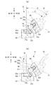
以上、説明した実施形態では、図3(a)に示すように、頭部側ボールジョイント62及び頭部50を前方側に大きく回動できる(矢印(2))。これにより、頭部50の前方側の可動範囲θを大きく確保でき、人形体10においてより良い適切なポーズが実現できる。
以上、説明した実施形態では、図3(a)に示すように、頭部側ボールジョイント62及び頭部50を前方側に大きく回動できる(矢印(2))。これにより、頭部50の前方側の可動範囲θを大きく確保でき、人形体10においてより良い適切なポーズが実現できる。
例えば、人形体10を、腕部40(図1参照)を水平方向に延ばしたポーズに変形するため、図3(b)に示すように、肩部42を上げても(矢印(3))大きな肩部42に対して大きな頭部50を前方側に逃がすことができる。その結果、肩部42と頭部50とが干渉することがなくなる。
これにより、図4に示すように、頭部50を自由に回動して顔部51を左右方向に向けることができ(矢印(4))、また、人形体10を左右方向から見たときも顔部51が肩部42に隠れることもない。さらに、銃11などを手部41aに取り付け、銃11を肩越しに構えたポーズにおいても、銃11などで顔部51が隠れにくくなり、より見栄えのよいポーズを得ることができる。
以上、実施形態を用いて本発明を説明したが、本発明の技術的範囲は上記実施形態に記載の範囲には限定されないことは言うまでもない。上記実施形態に、多様な変更又は改良を加えることが可能であることが当業者に明らかである。またその様な変更又は改良を加えた形態も本発明の技術的範囲に含まれ得ることが、特許請求の範囲の記載から明らかである。
例えば、本実施形態では、第2軸部63aを第1軸部62a(軸部)の中心を通る軸線Cから前方側に向けて延ばし、結果、胴部側ボールジョイント63b(胴部側ジョイント)が軸線C上から前方側に変位させた位置に設けられるようにしたが、第2軸部63aを軸線Cから後方側に向けて延ばし、胴部側ボールジョイント63bが軸線C上から後方側に変位させた位置に設けられるようにしても良い。すなわち、胴部側ボールジョイント63bを軸線C上から変位させる方向は後方でも良く、一側であれば任意である。つまり、第2軸部63aを突出させる方向も軸線C上から後方側でもよく、一側であれば任意である。
10 人形体
20 胴部
30 脚部
50 頭部
60 首の関節
61 関節本体
62 頭部側ボールジョイント(頭部側ジョイント)
62a 第1軸部(軸部)
62b 球体部
63a 第2軸部
63b 胴部側ボールジョイント(胴部側ジョイント)
20 胴部
30 脚部
50 頭部
60 首の関節
61 関節本体
62 頭部側ボールジョイント(頭部側ジョイント)
62a 第1軸部(軸部)
62b 球体部
63a 第2軸部
63b 胴部側ボールジョイント(胴部側ジョイント)
Claims (5)
- 胴部に頭部を回動可能に接続する人形体の首の関節であって、
関節本体と、
当該関節本体に設けられた頭部側ジョイントおよび胴部側ジョイントと、
を有し、
前記頭部側ジョイントは前記関節本体から延びる軸部を有し、
前記胴部側ジョイントは、前記軸部の軸線上から変位させた位置に設けられていることを特徴とする人形体の首の関節。 - 胴部に頭部を回動可能に接続する人形体の首の関節であって、
関節本体と、
当該関節本体に設けられた頭部側ジョイントおよび胴部側ジョイントと、
を有し、
前記頭部側ジョイントは前記関節本体から延びる軸部を有し、
前記胴部側ジョイントは、前記軸部の軸線から前後方向の一側側へ変位させた位置に設けられていることを特徴とする人形体の首の関節。 - 前記胴部側ジョイントが、前記軸部の軸線から前方側に変位させた位置に設けられていることを特徴とする請求項1乃至2のいずれか一項に記載の人形体の首の関節。
- 前記頭部側ジョイントおよび前記胴部側ジョイントはボールジョイントであることを特徴とする請求項1乃至3のいずれか1項に記載の人形体の首関節。
- 人形体であって、
請求項1乃至4のいずれか1項に記載の人形体の首の関節と、
前記首の関節を介して接続される胴部及び頭部と、
を備えることを特徴とする人形体。
Applications Claiming Priority (2)
| Application Number | Priority Date | Filing Date | Title |
|---|---|---|---|
| JP2014-132231 | 2014-06-27 | ||
| JP2014132231 | 2014-06-27 |
Publications (1)
| Publication Number | Publication Date |
|---|---|
| WO2015198727A1 true WO2015198727A1 (ja) | 2015-12-30 |
Family
ID=54937825
Family Applications (1)
| Application Number | Title | Priority Date | Filing Date |
|---|---|---|---|
| PCT/JP2015/063508 Ceased WO2015198727A1 (ja) | 2014-06-27 | 2015-05-11 | 人形体の首の関節及び人形体 |
Country Status (1)
| Country | Link |
|---|---|
| WO (1) | WO2015198727A1 (ja) |
Cited By (4)
| Publication number | Priority date | Publication date | Assignee | Title |
|---|---|---|---|---|
| CN110841303A (zh) * | 2018-11-16 | 2020-02-28 | 株式会社万代 | 人型玩具 |
| JP2020110711A (ja) * | 2018-11-16 | 2020-07-27 | 株式会社バンダイ | 人型玩具 |
| CN112535871A (zh) * | 2019-11-28 | 2021-03-23 | 株式会社万代 | 可动构造体和人形体 |
| CN113476866A (zh) * | 2018-06-29 | 2021-10-08 | 株式会社万代 | 臂构造和人型玩具 |
Citations (3)
| Publication number | Priority date | Publication date | Assignee | Title |
|---|---|---|---|---|
| JPS6023090U (ja) * | 1983-07-22 | 1985-02-16 | 株式会社 タカラ | ロボット玩具の関節構造 |
| JPS6148790U (ja) * | 1984-08-31 | 1986-04-01 | ||
| JP2013017590A (ja) * | 2011-07-08 | 2013-01-31 | Wiz Co Ltd | 玩具 |
-
2015
- 2015-05-11 WO PCT/JP2015/063508 patent/WO2015198727A1/ja not_active Ceased
Patent Citations (3)
| Publication number | Priority date | Publication date | Assignee | Title |
|---|---|---|---|---|
| JPS6023090U (ja) * | 1983-07-22 | 1985-02-16 | 株式会社 タカラ | ロボット玩具の関節構造 |
| JPS6148790U (ja) * | 1984-08-31 | 1986-04-01 | ||
| JP2013017590A (ja) * | 2011-07-08 | 2013-01-31 | Wiz Co Ltd | 玩具 |
Cited By (14)
| Publication number | Priority date | Publication date | Assignee | Title |
|---|---|---|---|---|
| CN113476866A (zh) * | 2018-06-29 | 2021-10-08 | 株式会社万代 | 臂构造和人型玩具 |
| JP2023171644A (ja) * | 2018-11-16 | 2023-12-01 | 株式会社バンダイ | 人型玩具 |
| JP2020089398A (ja) * | 2018-11-16 | 2020-06-11 | 株式会社バンダイ | 人型玩具 |
| JP2020110711A (ja) * | 2018-11-16 | 2020-07-27 | 株式会社バンダイ | 人型玩具 |
| CN110841303A (zh) * | 2018-11-16 | 2020-02-28 | 株式会社万代 | 人型玩具 |
| CN110841303B (zh) * | 2018-11-16 | 2022-02-25 | 株式会社万代 | 人型玩具 |
| JP7679437B2 (ja) | 2018-11-16 | 2025-05-19 | 株式会社バンダイ | 人型玩具 |
| CN114832390A (zh) * | 2018-11-16 | 2022-08-02 | 株式会社万代 | 人型玩具 |
| CN114832390B (zh) * | 2018-11-16 | 2024-07-02 | 株式会社万代 | 人型玩具 |
| JP7369085B2 (ja) | 2018-11-16 | 2023-10-25 | 株式会社バンダイ | 人型玩具 |
| CN112535871A (zh) * | 2019-11-28 | 2021-03-23 | 株式会社万代 | 可动构造体和人形体 |
| CN115282609A (zh) * | 2019-11-28 | 2022-11-04 | 株式会社万代 | 可动构造体和人形体 |
| CN112535871B (zh) * | 2019-11-28 | 2022-07-26 | 株式会社万代 | 可动构造体和人形体 |
| CN115282609B (zh) * | 2019-11-28 | 2025-09-23 | 株式会社万代 | 可动构造体和人形体 |
Similar Documents
| Publication | Publication Date | Title |
|---|---|---|
| CN101405063B (zh) | 人偶玩具 | |
| KR101780600B1 (ko) | 인형체의 견관절 구조 | |
| WO2015198727A1 (ja) | 人形体の首の関節及び人形体 | |
| KR101834085B1 (ko) | 인형체의 관절 구조 | |
| KR102699372B1 (ko) | 인형 | |
| JP6774540B1 (ja) | 関節構造及び人形体 | |
| US20150375127A1 (en) | Doll figure | |
| WO2006124640A3 (en) | Omnidirectional stereoscopic image capture and processing | |
| JP2016010685A (ja) | 人形体の首の関節及び人形体 | |
| CN106659941A (zh) | 人偶玩具的肩关节结构和人偶玩具 | |
| JP2017170113A (ja) | 人形玩具の手首関節構造及び人形玩具 | |
| JP5379887B2 (ja) | 人形体の腰部関節構造 | |
| TWI635445B (zh) | Double steering adjustment device for reading head of barcode reader | |
| KR20200030247A (ko) | 자석을 구비한 조인트 구조체 | |
| KR101681764B1 (ko) | 골프 클럽 헤드, 골프 클럽 | |
| JP6562894B2 (ja) | 人形体の肩関節構造 | |
| TW202007463A (zh) | 開關具有支撐功能之工具 | |
| JP2021023830A (ja) | 関節構造及び人形体 | |
| JP2019063339A (ja) | 人形の関節構造 | |
| JP5148003B1 (ja) | 人形玩具の関節構造 | |
| CN114534267B (zh) | 人形状玩具和模型的连结构件 | |
| JP2017169832A (ja) | 人形玩具の手首関節構造及び人形玩具 | |
| JP6920724B2 (ja) | Vr用メガネ | |
| USD746518S1 (en) | Attachment for headgear | |
| KR200409484Y1 (ko) | 삼중 관절 구조를 갖는 모형 인형 |
Legal Events
| Date | Code | Title | Description |
|---|---|---|---|
| 121 | Ep: the epo has been informed by wipo that ep was designated in this application |
Ref document number: 15812284 Country of ref document: EP Kind code of ref document: A1 |
|
| NENP | Non-entry into the national phase |
Ref country code: DE |
|
| 122 | Ep: pct application non-entry in european phase |
Ref document number: 15812284 Country of ref document: EP Kind code of ref document: A1 |