WO2015198372A1 - 生産機械 - Google Patents
生産機械 Download PDFInfo
- Publication number
- WO2015198372A1 WO2015198372A1 PCT/JP2014/066535 JP2014066535W WO2015198372A1 WO 2015198372 A1 WO2015198372 A1 WO 2015198372A1 JP 2014066535 W JP2014066535 W JP 2014066535W WO 2015198372 A1 WO2015198372 A1 WO 2015198372A1
- Authority
- WO
- WIPO (PCT)
- Prior art keywords
- production machine
- main body
- base
- machine main
- component
- Prior art date
- Legal status (The legal status is an assumption and is not a legal conclusion. Google has not performed a legal analysis and makes no representation as to the accuracy of the status listed.)
- Ceased
Links
Images





Classifications
-
- H—ELECTRICITY
- H05—ELECTRIC TECHNIQUES NOT OTHERWISE PROVIDED FOR
- H05K—PRINTED CIRCUITS; CASINGS OR CONSTRUCTIONAL DETAILS OF ELECTRIC APPARATUS; MANUFACTURE OF ASSEMBLAGES OF ELECTRICAL COMPONENTS
- H05K13/00—Apparatus or processes specially adapted for manufacturing or adjusting assemblages of electric components
Definitions
- the present invention relates to a production machine in which a production machine body is placed on a base.
- Patent Document 1 Japanese Patent No. 4746148
- FIG. 2 there is one in which a plurality of module-type component mounting machine bodies are placed on a base so as to be interchangeable along the conveyance direction of the circuit board.
- the component mounter main body suspends and supports the mounting head on an XY slide mechanism provided on the ceiling, and the mounting head is moved in the X direction and the Y direction by the XY slide mechanism to be supplied from the component supply device. Since the component to be mounted is attracted by the mounting head and mounted on the circuit board, the reaction force during acceleration / deceleration or stopping of the mounting head acts on the ceiling of the component mounting machine body, and the housing of the component mounting machine body There is a problem that the body is distorted, and a relative positional shift occurs between the position of the mounting head and the position of the circuit board carried by the conveyor, so that the component mounting accuracy is lowered. This problem becomes a serious problem because the reaction force at the time of acceleration / deceleration or stop of the mounting head increases as the moving speed of the mounting head increases to improve productivity.
- a problem to be solved by the present invention is to provide a production machine that can realize a reduction in size, width, and cost of a production machine main body (such as a component mounting machine main body).
- the present invention provides a production machine in which a production machine body is placed on a base, wherein the production machine body corresponds to a reaction force when a moving body inside the production machine moves.
- a sliding mechanism that slides on the base is provided.
- the production machine body since the production machine body slides on the base by the sliding mechanism according to the reaction force when the moving body inside the production machine moves, the production machine body generates the reaction force generated by the movement of the moving body. It can be converted into kinetic energy that slides on the table, and elastic energy (strain energy) accumulated in the housing of the production machine body can be greatly reduced.
- the distortion amount of the housing of the production machine main body can be greatly reduced, and the relative displacement between the position of the moving body (mounting head, etc.) in the production machine main body and the position of the workpiece can be reduced. Production accuracy can be improved. As a result, it is not necessary to reinforce the housing of the production machine body as in the conventional case, and the production machine body can be reduced in size, width, and cost.
- the sliding mechanism is provided with a sliding member made of a slippery material having a smaller coefficient of friction than the base on the base, and a leg provided at the bottom of the production machine body is mounted on the upper surface of the sliding member. It may be configured to be placed and slid. In this way, the sliding mechanism can be configured with a very simple configuration and at a low cost.
- the sliding member is provided on the base so as to extend in the front-rear direction, which is the insertion / removal direction of the production machine main body, and the upper surface of the sliding member has a concave curved surface shape with the lowest portion extending in the insertion / removal direction of the production machine main body.
- the leg of the production machine main body may be configured to slide in the direction of taking in and out of the production machine main body along the lowest part of the upper surface of the sliding member when the production machine main body is taken in and out. If it does in this way, a sliding member can be utilized also as a guide member which guides taking in / out of a production machine main body.
- a return urging mechanism for urging the production machine main body in the direction of the predetermined position so that the production machine main body slid on the base is returned to the predetermined position.
- the return urging mechanism is provided with an elastic member on the base, and the elastic member is detachably connected to the bottom of the production machine main body by a connection mechanism, and the production machine main body is connected by the elastic force of the elastic member. You may comprise so that it may urge in the direction of the said predetermined position. In this way, even if the production machine main body slides on the base in any direction from the predetermined position, the production machine main body can be returned to the predetermined position before the slide by the elastic force of the elastic member.
- the present invention provides a plurality of production machine main bodies placed on the base along the workpiece conveyance direction, and a conveyance for guiding the work unloaded from each production machine main body toward the carry-in port of the adjacent production machine main body. It is good also as a structure which provided the guide member. In this way, even when a plurality of production machine main bodies slide in different directions due to reaction forces during operation, workpiece transfer between the production machine main bodies can be smoothly performed by the transport guide member.
- the present invention can be applied to various production machines.
- the present invention may be applied to a component mounter or a component assembly machine that mounts or assembles components on a circuit board.
- component mounters and component assembly machines are designed to suspend the mounting head on the XY slide mechanism provided on the ceiling of the housing, so the mounting head speed is increased with the conventional structure. Then, when the mounting head is accelerated / decelerated or stopped, the reaction force acting on the housing increases, and the amount of distortion of the housing increases, resulting in a relative displacement between the mounting head position and the circuit board position. As the size increases, the component mounting accuracy decreases. If the present invention is applied to a component mounting machine or a component assembling machine to significantly reduce the amount of distortion of the casing that causes a decrease in component mounting accuracy, the component mounting accuracy can be improved.
- FIG. 1 is a perspective view of a component mounter showing an embodiment of the present invention.
- FIG. 2 is a perspective view of the base.
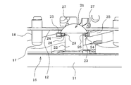
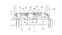
- FIG. 3 is a perspective view illustrating the configuration of the return biasing mechanism.
- FIG. 4 is a perspective view showing a state after the clamping of the return urging mechanism is completed.
- FIG. 5 is a perspective view showing the same state as FIG. 4 with the elastic member removed.
- FIG. 6 is a perspective view of the same state as FIG. 4 as viewed obliquely from below.
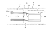
- FIG. 7 is a plan view showing an example of the conveyance guide mechanism.
- FIG. 8 is a plan view showing another example of the transport guide mechanism.
- FIG. 9 is a longitudinal sectional view showing another example of the sliding mechanism.
- the component mounting system is configured such that a plurality of component mounter main bodies 12 (production machine main bodies) are placed on the base 11 so as to be able to be taken in and out along the conveying direction of the circuit board 13 (workpiece: see FIG. 7). ing.
- Each component mounter main body 12 includes a conveyor 14 (see FIG.
- each component mounter main body 12 that conveys the circuit board 13, a component supply device (not shown) that supplies components to be mounted, and the like, and a ceiling portion of each component mounter main body 12
- the mounting head (not shown) is suspended and supported by an XY slide mechanism (not shown) provided on the XY slide mechanism, and the mounting head is moved in the X direction and the Y direction by the XY slide mechanism and supplied from the component supply device. The components are sucked by the mounting head and mounted on the circuit board 13.
- Each component mounter main body 12 is placed on the base 11 via a sliding mechanism 16 and is generated when each component mounter main body 12 is operated (specifically, when the mounting head is accelerated / decelerated or stopped).
- Each component mounting machine body 12 is slid on the base 11 by a sliding mechanism 16 in accordance with the force.
- the sliding mechanism 16 includes a plurality of sliding members 17 on the base 11, and legs provided at, for example, four locations on the bottom of the component mounting machine body 12.
- the portion 18 is configured to slide on the upper surfaces of the two sliding members 17.
- Two sliding members 17 are provided for each component mounting machine main body 12 placed on the base 11, and are slippery materials having a smaller friction coefficient than the base 11 (the friction coefficient is preferably 0.1 or less, more preferably Is about 0.03) and is made of a material having excellent wear resistance (for example, a fluororesin).
- the sliding member 17 is provided on the base 11 so as to extend in the front-rear direction, which is the insertion / removal direction of the component mounting machine body 12, and the uppermost portion of the sliding member 17 has the lowest portion of the component mounting machine body 12.
- the leg 18 of the component mounting machine main body 12 extends along the lowest part of the upper surface of the sliding member 17 in the loading / unloading direction of the component mounting machine main body 12. It is configured to slide.
- the sliding member 17 functions also as a guide member which guides taking in / out of the component mounting machine main body 12.
- the lower end surface of the leg part 18 of the component mounting machine main body 12 is formed in a round shape like a pan bottom so that it can easily slide on the sliding member 17.
- the component mounter main body 12 is moved in the direction of the predetermined position as means for returning the component mounter main body 12 slid on the base 11 to a predetermined position (position before the slide).
- the return urging mechanism 21 for urging is provided at one place or a plurality of places (for example, front and rear two places).
- the return urging mechanism 21 fixes a bar-shaped elastic member 22 upward on the base 11, and connects the upper part of the elastic member 22 to the bottom of the component mounting machine body 12 in a detachable manner by a connecting mechanism 23.
- the component mounter main body 12 is urged toward the predetermined position by the elastic force of the elastic member 22.
- the elastic member 22 is formed of an elastic material having high durability and a high restoration rate (elastic modulus) (for example, a rubber-based material appropriately mixed with silicone or the like).
- the coupling mechanism 23 has a pair of U-shaped guide rails 25 fitted to both ends of the coupling bar 24 and fixed to the upper part of the elastic member 22 by penetrating the coupling bar 24 in the left-right direction. 12 is fixed so as to extend in the front-rear direction, which is the insertion / removal direction of the component mounter main body 12, and both end portions of the connection bar 24 are hooked by the connection fittings 26 on the bottom surface portion of the component mounter main body 12.
- a pull-in device 27 for pulling the component mounter main body 12 to the predetermined position is provided.
- the pull-in device 27 When the component mounter main body 12 is put in and out, the pull-in device 27 is operated to move the connection fitting 26 to a position removed from the connection bar 24, and then the leg 18 of the component mounter main body 12 is moved back and forth on the sliding member 17.
- the component mounter main body 12 is taken in and out by sliding in the direction.
- rollers are rotatably provided at both end portions of the connecting bar 24, and the rollers are fitted to the guide rail 25 to connect the connecting bar 24.
- the frictional resistance between both ends of the guide rail 25 and the guide rail 25 may be reduced.
- a conveyance guide member 30 for guiding the circuit board 13 carried out by the conveyor 14 from the carry-out port 28 of the component mounter body 12 toward the carry-in port 29 of the adjacent component mounter body 12 is provided with the component mounting.
- the transfer guide member 30 is pivotally attached to the side edge of the carry-out port 28 of the machine body 12, and the leading end of the conveyance guide member 30 is connected to the side edge of the carry-in port 29 of the adjacent component mounting machine body 12 by engagement or the like. ing. Accordingly, the conveyance guide member 30 is rotationally displaced according to the sliding of each component mounter main body 12, and the transfer of the circuit board 13 between the component mounter main bodies 12 is guided by the conveyance guide member 30.
- the component mounter main body 12 is placed on the base 11 via the sliding mechanism 16, and the component mounter main body 12 according to the reaction force during operation of the component mounter main body 12. Is configured to slide on the base 11, the reaction force when the mounting head of the component mounter body 12 moves can be converted into kinetic energy for the component mounter body 12 to slide on the base 11.
- the elastic energy (strain energy) accumulated in the housing of the component mounter body 12 can be greatly reduced.
- casing of the component mounting machine main body 12 can be reduced significantly, and the relative position shift between the position of the mounting head of the component mounting machine main body 12 and the position of a workpiece
- work can be made small.
- Component mounting accuracy can be improved. As a result, it is not necessary to reinforce the housing of the component mounter body 12 as in the conventional case, and the component mounter body 12 can be reduced in size, width, and cost.
- the sliding mechanism 16 is provided with the sliding member 17 formed of a slippery material having a small friction coefficient on the base 11 and the leg portion 18 provided at the bottom of the component mounting machine body 12 with the sliding member. Since it is configured to be slid by being placed on the upper surface of 17, there is an advantage that the sliding mechanism 16 can be configured with a very simple configuration and at low cost.
- the sliding member 17 is provided on the base 11 so as to extend in the front-rear direction, which is the direction in which the component mounting body 12 is put in and out, and the uppermost portion of the sliding member 17 is mounted with the lowest part.
- the component mounting machine main body 12 is formed in a concave curved surface extending in the loading / unloading direction of the machine main body 12, and the leg 18 of the component mounting machine main body 12 extends along the lowest part of the upper surface of the sliding member 17 when the component mounting machine main body 12 is put in and out. Since the sliding member 17 can be used as a guide member for guiding the mounting / removal of the component mounting machine body 12, the sliding operation of the component mounting machine body 12 can be easily performed. Can do.
- a return bias for urging the component mounter main body 12 in the direction of the predetermined position (position before the slide). Since the mechanism 21 is provided, it is possible to prevent the sliding range of the component mounter main body 12 on the base 11 from being excessively widened by the return biasing mechanism 21, and the component mounter main body 12 on the base 11 can be prevented.
- the sliding range can be limited to an appropriate range.
- the return biasing mechanism 21 is provided with an elastic member 22 on the base 11, and the elastic member 22 is detachably connected to the bottom of the component mounting machine body 12 by a connecting mechanism 23. Since the component mounter main body 12 is urged by the force in the direction of the predetermined position, the elastic member 22 can be used regardless of the direction in which the component mounter main body 12 slides on the base 11 from the predetermined position. The component mounter main body 12 can be returned to a predetermined position before sliding by the elastic force.
- the conveyance guide member 30 is rotatably attached to the side edge of the carry-out port 28 of the component mounter main body 12, but as shown in FIG.
- the roller type guide 31 that flexibly deforms accordingly is used as a conveyance guide member, and the roller type guide 31 connects between the carry-out port 28 of the component mounter body 12 and the carry-in port 29 of the adjacent component mounter body 12. Then, the circuit board 13 carried out by the conveyor 14 from the carry-out port 28 of the component mounter body 12 may be guided by the roller guide 31 toward the carry-in port 29 of the adjacent component mounter body 12. Even in this case, the delivery of the component mounter main body 12 between the component mounter main bodies 12 can be performed smoothly.
- the lower end surface of the leg portion 18 of the component mounting machine body 12 is formed in a round shape like a pot bottom so as to be easily slidable on the sliding member 17, as shown in FIG.
- the ball 32 is rotatably provided at the lower end portion of the leg portion 18 of the component mounter body 12 so as to protrude downward, and the component mounter body 12 is placed on the base 11.
- the sliding member 17 may not be provided on the base 11.
- the present invention is not limited to a component mounting machine, and may be applied to a component assembly machine that assembles components such as connectors on a circuit board. Further, the reaction force of the production machine main body causes a reaction of the production machine main body.
- the present invention can be widely applied to production machines in which the housing may be distorted and the production accuracy may be lowered.
- a sliding member may be provided on almost the entire upper surface of the base 11, or the number of the leg portions 18 of the component mounter body 12 may be increased. Needless to say, various modifications can be made.
- SYMBOLS 11 Base, 12 ... Component mounting machine main body (production machine main body), 13 ... Circuit board 13 (workpiece
Landscapes
- Engineering & Computer Science (AREA)
- Manufacturing & Machinery (AREA)
- Microelectronics & Electronic Packaging (AREA)
- Supply And Installment Of Electrical Components (AREA)
- Automatic Assembly (AREA)
Abstract
部品実装機本体(12)を基台(11)上に滑り機構(16)を介して載置し、部品実装機本体(12)の稼働時の反力に応じて部品実装機本体(12)が基台(11)上を滑動するようにする。滑り機構(16)は、基台(11)上に2つの滑り部材(17)を設けると共に、部品実装機本体(12)の底部の4箇所に設けた脚部(18)を2つの滑り部材(17)の上面に載置して滑動させる。滑り部材(17)は、基台(11)上に部品実装機本体(12)の出し入れ方向に延びるように設けられ、該滑り部材(17)の上面は、最も低い部分が部品実装機本体(12)の出し入れ方向である前後方向に延びる凹曲面状に形成され、部品実装機本体(12)の出し入れ時に部品実装機本体(12)の脚部(18)が滑り部材(17)の上面の最も低い部分に沿って部品実装機本体(12)の出し入れ方向にスライドする。
Description
本発明は、基台上に生産機械本体を載置した生産機械に関する発明である。
近年、例えば、複数の部品実装機を配列した部品実装ラインにおいては、生産する品種の多様化に対応して部品実装機の入れ替えを容易にするために、特許文献1(特許第4746148号公報)に示すように、基台上に回路基板の搬送方向に沿って複数のモジュール型の部品実装機本体を入れ替え可能に載置するようにしたものがある。
ところで、部品実装機本体は、その天井部に設けたXYスライド機構に装着ヘッドを吊り下げて支持し、XYスライド機構により装着ヘッドをX方向やY方向に移動させて、部品供給装置から供給される部品を装着ヘッドで吸着して回路基板に実装するようにしているため、装着ヘッドの加減速時や停止時の反力が部品実装機本体の天井部に作用して部品実装機本体の筐体が歪み、装着ヘッドの位置とコンベアで搬入された回路基板の位置との間に相対的な位置ずれが生じて、部品装着精度が低下するという問題があった。この問題は、生産性向上のために装着ヘッドの移動速度を高速化するほど、装着ヘッドの加減速時や停止時の反力が大きくなるため、大きな問題となる。
従来、このような問題を解決する手段として、部品実装機本体の筐体の剛性を高める対策を施して、装着ヘッドの加減速時や停止時の反力による部品実装機本体の筐体の歪みを小さくするようにしていた。その結果、部品実装機本体の大型化・幅広化や、補強部品によるコスト高を招いていた。
そこで、本発明が解決しようとする課題は、生産機械本体(部品実装機本体等)の小型化・幅狭化や低コスト化を実現できる生産機械を提供することである。
上記課題を解決するために、本発明は、基台上に生産機械本体を載置した生産機械において、前記生産機械内部の移動体が移動した時の反力に応じて前記生産機械本体が前記基台上を滑動する滑り機構を設けた構成としたものである。この構成では、生産機械内部の移動体が移動した時の反力に応じて生産機械本体が基台上を滑り機構により滑動するため、移動体の移動によって生じる反力を、生産機械本体が基台上を滑動する運動エネルギに変換することができ、生産機械本体の筐体に蓄積される弾性エネルギ(歪みエネルギ)を大幅に低減できる。これにより、生産機械本体の筐体の歪み量を大幅に低減できて、生産機械本体内の移動体(装着ヘッド等)の位置とワークの位置との間の相対的な位置ずれを小さくすることができ、生産精度を向上できる。その結果、生産機械本体の筐体を従来のように補強する必要がなくなり、生産機械本体の小型化・幅狭化や低コスト化を実現できる。
この場合、滑り機構は、基台上に該基台よりも摩擦係数の小さい滑り易い材料で形成した滑り部材を設けると共に、生産機械本体の底部に設けた脚部を前記滑り部材の上面に載置して滑動させるように構成しても良い。このようにすれば、滑り機構を極めて簡単な構成で且つ安価に構成できる。
また、滑り部材を、基台上に生産機械本体の出し入れ方向である前後方向に延びるように設けると共に、該滑り部材の上面を、最も低い部分が生産機械本体の出し入れ方向に延びる凹曲面状に形成し、前記生産機械本体の出し入れ時に前記生産機械本体の脚部が前記滑り部材の上面の最も低い部分に沿って前記生産機械本体の出し入れ方向にスライドするように構成しても良い。このようにすれば、滑り部材を、生産機械本体の出し入れを案内する案内部材としても利用することができる。
また、本発明は、基台上を滑動した生産機械本体を所定位置に戻すように生産機械本体を前記所定位置の方向へ付勢する戻し付勢機構を設けるようにすると良い。このようにすれば、基台上の生産機械本体の滑動範囲が広がり過ぎるのを戻し付勢機構により防止することができ、基台上の生産機械本体の滑動範囲を適正範囲内に制限することができる。
この場合、戻し付勢機構は、基台上に弾性部材を設けると共に、前記弾性部材を生産機械本体の底部に連結機構により切り離し可能に連結し、前記弾性部材の弾性力により前記生産機械本体を前記所定位置の方向へ付勢するように構成しても良い。このようにすれば、基台上を生産機械本体が所定位置からどの様な方向へ滑動しても、弾性部材の弾性力により生産機械本体を滑動前の所定位置の方向へ戻すことができる。
また、本発明は、基台上にワークの搬送方向に沿って複数の生産機械本体を載置し、各生産機械本体から搬出するワークを隣の生産機械本体の搬入口に向かって案内する搬送案内部材を設けた構成としても良い。このようにすれば、複数の生産機械本体が稼働時の反力により互いに異なる方向に滑動しても、各生産機械本体間のワークの受け渡しを搬送案内部材によりスムーズに行うことができる。
本発明は、様々な生産機械に適用可能であり、例えば、回路基板に部品を実装又は組み立てる部品実装機や部品組立機に本発明を適用しても良い。前述したように、部品実装機や部品組立機は、筐体の天井部に設けたXYスライド機構に装着ヘッドを吊り下げるようにしているため、従来構造のままで装着ヘッドの移動速度を高速化すると、装着ヘッドの加減速時や停止時に筐体に作用する反力が大きくなって筐体の歪み量が大きくなり、装着ヘッドの位置と回路基板の位置との間の相対的な位置ずれが大きくなって、部品装着精度が低下する。本発明を部品実装機や部品組立機に適用して、部品装着精度低下の原因となる筐体の歪み量を大幅に減少させれば、部品装着精度を向上できる。
以下、本発明を実施するための形態を部品実装システムに適用して具体化した一実施例を説明する。
まず、図1に基づいて部品実装システム全体の構成を説明する。
部品実装システムは、基台11上に、回路基板13(ワーク:図7参照)の搬送方向に沿って複数の部品実装機本体12(生産機械本体)が出し入れ可能に載置される構成となっている。各部品実装機本体12は、回路基板13を搬送するコンベア14(図7参照)と、実装する部品を供給する部品供給装置(図示せず)等を備え、各部品実装機本体12の天井部に設けたXYスライド機構(図示せず)に装着ヘッド(図示せず)を吊り下げて支持させ、XYスライド機構により装着ヘッドをX方向やY方向に移動させて、部品供給装置から供給される部品を装着ヘッドで吸着して回路基板13に実装するようにしている。
部品実装システムは、基台11上に、回路基板13(ワーク:図7参照)の搬送方向に沿って複数の部品実装機本体12(生産機械本体)が出し入れ可能に載置される構成となっている。各部品実装機本体12は、回路基板13を搬送するコンベア14(図7参照)と、実装する部品を供給する部品供給装置(図示せず)等を備え、各部品実装機本体12の天井部に設けたXYスライド機構(図示せず)に装着ヘッド(図示せず)を吊り下げて支持させ、XYスライド機構により装着ヘッドをX方向やY方向に移動させて、部品供給装置から供給される部品を装着ヘッドで吸着して回路基板13に実装するようにしている。
各部品実装機本体12は基台11上に滑り機構16を介して載置され、各部品実装機本体12の稼働時(具体的には装着ヘッドの加減速時や停止時)に発生する反力に応じて各部品実装機本体12が基台11上を滑り機構16により滑動するようになっている。滑り機構16は、図1、図2、図5、図6に示すように、基台11上に複数の滑り部材17を設けると共に、部品実装機本体12の底部の例えば4箇所に設けた脚部18を2つの滑り部材17の上面に載置して滑動させるように構成されている。滑り部材17は、基台11上に載置する部品実装機本体12毎に2つずつ設けられ、基台11よりも摩擦係数の小さい滑り易い材料(摩擦係数が例えば0.1以下、より好ましくは0.03程度)で且つ耐摩耗性に優れた材料(例えばフッ素系樹脂)で形成されている。滑り部材17は、基台11上に部品実装機本体12の出し入れ方向である前後方向に延びるように設けられていると共に、該滑り部材17の上面は、最も低い部分が部品実装機本体12の出し入れ方向に延びる凹曲面状に形成され、部品実装機本体12の出し入れ時に部品実装機本体12の脚部18が滑り部材17の上面の最も低い部分に沿って部品実装機本体12の出し入れ方向にスライドするように構成されている。これにより、滑り部材17は、部品実装機本体12の出し入れを案内する案内部材としても機能するようになっている。また、部品実装機本体12の脚部18の下端面は、滑り部材17上を滑りやすいように鍋底状の丸みのある形状に形成されている。
更に、図3乃至図6に示すように、基台11上を滑動した部品実装機本体12を所定位置(滑動前の位置)に戻す手段として、部品実装機本体12を前記所定位置の方向へ付勢する戻し付勢機構21が1箇所又は複数箇所(例えば前後2箇所)に設けられている。戻し付勢機構21は、基台11上に棒状の弾性部材22を上向きに固定すると共に、該弾性部材22の上部を部品実装機本体12の底部に連結機構23により切り離し可能に連結し、該弾性部材22の弾性力により部品実装機本体12を前記所定位置の方向へ付勢するように構成されている。弾性部材22は、耐久性と復元率(弾性率)が高い弾性材料(例えばシリコーン等を適切に配合したゴム系材料)で形成されている。
連結機構23は、弾性部材22の上部に連結バー24を左右方向に貫通して固定すると共に、連結バー24の両端部を嵌合する一対の断面コ字形のガイドレール25を、部品実装機本体12の底面部に該部品実装機本体12の出し入れ方向である前後方向に延びるように固定し、更に、部品実装機本体12の底面部には、連結バー24の両端部を連結金具26で引っ掛けて該部品実装機本体12を前記所定位置まで引き込む引き込み装置27を設けた構成となっている。部品実装機本体12を出し入れするときには、引き込み装置27を動作させて連結金具26を連結バー24から外した位置へ移動させた後、部品実装機本体12の脚部18を滑り部材17上を前後方向に滑らせて部品実装機本体12を出し入れする。この際、連結バー24の両端部がガイドレール25に沿ってスライドするため、連結バー24の両端部にローラを回転可能に設けて、このローラをガイドレール25に嵌合して、連結バー24の両端部とガイドレール25との間の摩擦抵抗を低減するようにしても良い。
図7に示すように、部品実装機本体12の搬出口28からコンベア14で搬出する回路基板13を隣の部品実装機本体12の搬入口29に向かって案内する搬送案内部材30が該部品実装機本体12の搬出口28の側縁部に回動可能に取り付けられ、該搬送案内部材30の先端部が隣の部品実装機本体12の搬入口29の側縁部に係合等により連結されている。これにより、各部品実装機本体12の滑動に応じて搬送案内部材30が回動変位して、各部品実装機本体12間の回路基板13の受け渡しが搬送案内部材30によって案内される。
以上説明した本実施例によれば、基台11上に滑り機構16を介して部品実装機本体12を載置し、部品実装機本体12の稼働時の反力に応じて部品実装機本体12が基台11上を滑動するように構成したので、部品実装機本体12の装着ヘッド移動時の反力を、部品実装機本体12が基台11上を滑動する運動エネルギに変換することができ、部品実装機本体12の筐体に蓄積される弾性エネルギ(歪みエネルギ)を大幅に低減できる。これにより、部品実装機本体12の筐体の歪み量を大幅に低減できて、部品実装機本体12の装着ヘッドの位置とワークの位置との間の相対的な位置ずれを小さくすることができ、部品装着精度を向上できる。その結果、部品実装機本体12の筐体を従来のように補強する必要がなくなり、部品実装機本体12の小型化・幅狭化や低コスト化を実現できる。
しかも、本実施例では、滑り機構16は、基台11上に摩擦係数の小さい滑り易い材料で形成した滑り部材17を設けると共に、部品実装機本体12の底部に設けた脚部18を滑り部材17の上面に載置して滑動させるように構成したので、滑り機構16を極めて簡単な構成で且つ安価に構成できる利点がある。
また、本実施例では、滑り部材17を、基台11上に部品実装機本体12の出し入れ方向である前後方向に延びるように設けると共に、該滑り部材17の上面を、最も低い部分が部品実装機本体12の出し入れ方向に延びる凹曲面状に形成し、部品実装機本体12の出し入れ時に部品実装機本体12の脚部18が滑り部材17の上面の最も低い部分に沿って部品実装機本体12の出し入れ方向にスライドするように構成したので、滑り部材17を、部品実装機本体12の出し入れを案内する案内部材としても利用することができ、部品実装機本体12の出し入れ作業を容易に行うことができる。
また、本実施例では、基台11上を滑動した部品実装機本体12を所定位置に戻す手段として、部品実装機本体12を所定位置(滑動前の位置)の方向へ付勢する戻し付勢機構21を設けるようにしたので、基台11上の部品実装機本体12の滑動範囲が広がり過ぎるのを戻し付勢機構21により防止することができ、基台11上の部品実装機本体12の滑動範囲を適正範囲内に制限することができる。
しかも、戻し付勢機構21は、基台11上に弾性部材22を設けると共に、この弾性部材22を部品実装機本体12の底部に連結機構23により切り離し可能に連結し、前記弾性部材22の弾性力により部品実装機本体12を前記所定位置の方向へ付勢するように構成したので、基台11上を部品実装機本体12が所定位置からどの様な方向へ滑動しても、弾性部材22の弾性力により部品実装機本体12を滑動前の所定位置の方向へ戻すことができる。
また、本実施例では、基台11上に回路基板13の搬送方向に沿って複数の部品実装機本体12を並べて載置し、部品実装機本体12の搬出口28からコンベア14で搬出する回路基板13を隣の部品実装機本体12の搬入口29に向かって案内する搬送案内部材30を設けた構成としたので、複数の部品実装機本体12が稼働時の反力により互いに異なる方向に滑動しても、各部品実装機本体12間の部品実装機本体12の受け渡しを搬送案内部材30によりスムーズに行うことができる。
本実施例では、搬送案内部材30を該部品実装機本体12の搬出口28の側縁部に回動可能に取り付けるようにしたが、図8に示すように、部品実装機本体12の滑動に応じて柔軟に湾曲変形するローラ式ガイド31を搬送案内部材として用い、部品実装機本体12の搬出口28とその隣の部品実装機本体12の搬入口29との間をローラ式ガイド31で接続し、部品実装機本体12の搬出口28からコンベア14で搬出する回路基板13をローラ式ガイド31によって隣の部品実装機本体12の搬入口29に向かって案内するようにしても良い。このようにしても、各部品実装機本体12間の部品実装機本体12の受け渡しをスムーズに行うことができる。
また、本実施例の滑り機構16では、部品実装機本体12の脚部18の下端面を、滑り部材17上を滑りやすいように鍋底状の丸みのある形状に形成したが、図9に示す滑り機構33のように、部品実装機本体12の脚部18の下端部にボール32を下方に突出させるように回転可能に設け、基台11上に部品実装機本体12を載置して該部品実装機本体12の荷重をボール32で受け支えさせることで、部品実装機本体12の稼働時の反力に応じて部品実装機本体12を基台11上をボール32の回転により滑動させるようにしても良い。この場合は、基台11上に滑り部材17を設けなくても良い。
尚、本発明は、部品実装機に限定されず、回路基板にコネクタ等の部品を組み立てる部品組立機に適用しても良く、更には、生産機械本体の稼働時の反力により生産機械本体の筐体が歪んで生産精度が低下する可能性のある生産機械に広く適用して実施できる。
その他、本発明は、基台11の上面のほぼ全面に滑り部材を設けたり、或は、部品実装機本体12の脚部18の本数を増加させても良い等、要旨を逸脱しない範囲内で種々変更して実施できることは言うまでもない。
11…基台、12…部品実装機本体(生産機械本体)、13…回路基板13(ワーク)、14…コンベア、16…滑り機構、17…滑り部材、18…脚部、21…戻し付勢機構、22…弾性部材、23…連結機構、24…連結バー、25…ガイドレール、26…連結金具、27…引き込み装置、28…搬出口、29…搬入口、30…搬送案内部材、31…ローラ式ガイド(搬送案内部材)、32…ボール、33…滑り機構
Claims (7)
- 基台上に生産機械本体を載置した生産機械において、
前記生産機械本体の移動体が移動した時の反力に応じて前記生産機械本体が前記基台上を滑動する滑り機構を設けたことを特徴とする生産機械。 - 前記滑り機構は、前記基台上に該基台よりも摩擦係数の小さい滑り易い材料で形成した滑り部材を設けると共に、前記生産機械本体の底部に設けた脚部を前記滑り部材の上面に載置して滑動させるように構成されていることを特徴とする請求項1に記載の生産機械。
- 前記滑り部材は、前記基台上に前記生産機械本体の出し入れ方向である前後方向に延びるように設けられ、
前記滑り部材の上面は、最も低い部分が前記生産機械本体の出し入れ方向に延びる凹曲面状に形成され、前記生産機械本体の出し入れ時に前記生産機械本体の脚部が前記滑り部材の上面の最も低い部分に沿って前記生産機械本体の出し入れ方向にスライドするように構成されていることを特徴とする請求項2に記載の生産機械。 - 前記基台上を滑動した前記生産機械本体を所定位置に戻すように前記生産機械本体を前記所定位置の方向へ付勢する戻し付勢機構を設けたことを特徴とする請求項1乃至3のいずれかに記載の生産機械。
- 前記戻し付勢機構は、前記基台上に弾性部材を設けると共に、前記弾性部材を前記生産機械本体の底部に連結機構により切り離し可能に連結し、前記弾性部材の弾性力により前記生産機械本体を前記所定位置の方向へ付勢するように構成されていることを特徴とする請求項4に記載の生産機械。
- 前記基台上にワークの搬送方向に沿って複数の生産機械本体を載置し、各生産機械本体から搬出するワークを隣の生産機械本体の搬入口に向かって案内する搬送案内部材を設けたことを特徴とする請求項1乃至5のいずれかに記載の生産機械。
- 前記生産機械本体は、回路基板に部品を実装又は組み立てる部品実装機本体又は部品組立機本体であることを特徴とする請求項1乃至6のいずれかに記載の生産機械。
Priority Applications (2)
| Application Number | Priority Date | Filing Date | Title |
|---|---|---|---|
| PCT/JP2014/066535 WO2015198372A1 (ja) | 2014-06-23 | 2014-06-23 | 生産機械 |
| JP2016528766A JP6374963B2 (ja) | 2014-06-23 | 2014-06-23 | 生産機械 |
Applications Claiming Priority (1)
| Application Number | Priority Date | Filing Date | Title |
|---|---|---|---|
| PCT/JP2014/066535 WO2015198372A1 (ja) | 2014-06-23 | 2014-06-23 | 生産機械 |
Publications (1)
| Publication Number | Publication Date |
|---|---|
| WO2015198372A1 true WO2015198372A1 (ja) | 2015-12-30 |
Family
ID=54937511
Family Applications (1)
| Application Number | Title | Priority Date | Filing Date |
|---|---|---|---|
| PCT/JP2014/066535 Ceased WO2015198372A1 (ja) | 2014-06-23 | 2014-06-23 | 生産機械 |
Country Status (2)
| Country | Link |
|---|---|
| JP (1) | JP6374963B2 (ja) |
| WO (1) | WO2015198372A1 (ja) |
Citations (6)
| Publication number | Priority date | Publication date | Assignee | Title |
|---|---|---|---|---|
| JP2002217590A (ja) * | 2001-01-18 | 2002-08-02 | Yamagata Casio Co Ltd | トレイ電子部品搭載装置 |
| JP2005064222A (ja) * | 2003-08-12 | 2005-03-10 | Matsushita Electric Ind Co Ltd | 部品実装機用架台及び部品実装機 |
| JP2006075958A (ja) * | 2004-09-10 | 2006-03-23 | Toshiba Mach Co Ltd | 駆動システムおよび加工システム |
| JP2006255844A (ja) * | 2005-03-17 | 2006-09-28 | Amada Co Ltd | 工作機械 |
| JP2011146578A (ja) * | 2010-01-15 | 2011-07-28 | Fuji Mach Mfg Co Ltd | 台車および電子部品実装機 |
| JP2013202708A (ja) * | 2012-03-27 | 2013-10-07 | Hitachi Via Mechanics Ltd | 加工機 |
-
2014
- 2014-06-23 JP JP2016528766A patent/JP6374963B2/ja active Active
- 2014-06-23 WO PCT/JP2014/066535 patent/WO2015198372A1/ja not_active Ceased
Patent Citations (6)
| Publication number | Priority date | Publication date | Assignee | Title |
|---|---|---|---|---|
| JP2002217590A (ja) * | 2001-01-18 | 2002-08-02 | Yamagata Casio Co Ltd | トレイ電子部品搭載装置 |
| JP2005064222A (ja) * | 2003-08-12 | 2005-03-10 | Matsushita Electric Ind Co Ltd | 部品実装機用架台及び部品実装機 |
| JP2006075958A (ja) * | 2004-09-10 | 2006-03-23 | Toshiba Mach Co Ltd | 駆動システムおよび加工システム |
| JP2006255844A (ja) * | 2005-03-17 | 2006-09-28 | Amada Co Ltd | 工作機械 |
| JP2011146578A (ja) * | 2010-01-15 | 2011-07-28 | Fuji Mach Mfg Co Ltd | 台車および電子部品実装機 |
| JP2013202708A (ja) * | 2012-03-27 | 2013-10-07 | Hitachi Via Mechanics Ltd | 加工機 |
Also Published As
| Publication number | Publication date |
|---|---|
| JPWO2015198372A1 (ja) | 2017-04-20 |
| JP6374963B2 (ja) | 2018-08-15 |
Similar Documents
| Publication | Publication Date | Title |
|---|---|---|
| KR102484881B1 (ko) | 반송 장치, 수지 성형 장치, 반송 방법 및 수지 성형품의 제조 방법 | |
| CN106471876B (zh) | 带式供料器 | |
| CN106985504B (zh) | 一种3d增材印花机网框自动装卸系统 | |
| KR20140082872A (ko) | 트레이 공급장치 | |
| CN105493652A (zh) | 对基板作业装置 | |
| JP6797596B2 (ja) | パーツフィーダ及び製造作業機 | |
| KR101326475B1 (ko) | 패턴 재봉틀의 이송 장치 | |
| CN210709538U (zh) | 一种回流拉带机构 | |
| JP5728514B2 (ja) | 基板コンベヤ | |
| CN104704940A (zh) | 支撑销及基板处理装置 | |
| JP6374963B2 (ja) | 生産機械 | |
| KR200471191Y1 (ko) | 재단 철판 이송 후 적재시 전후 좌우 가이드 장치에 있어서, 앤드 스토퍼의 회전 작동 장치 | |
| CN107855407B (zh) | 一种冲压流水线 | |
| KR101563503B1 (ko) | 장갑 코팅기의 장갑장착모듈 회전장치 | |
| CN107098135B (zh) | 手机彩盒上料机构 | |
| CN205237685U (zh) | 用于输送料架的前限位机构 | |
| US8052371B2 (en) | Bag supply apparatus | |
| JP2017224712A (ja) | 部品実装装置 | |
| JP6578138B2 (ja) | ワークキャリッジ及びワーク搬送装置 | |
| KR101187397B1 (ko) | 도금용 랙 어셈블리 | |
| JP2005054884A (ja) | 往復駆動装置、および搬送装置、ネジ締め装置 | |
| JP2010129879A (ja) | 基板支持装置 | |
| KR200446479Y1 (ko) | 왕복진동식 컨베이어 | |
| CN106141772B (zh) | 用于加工机械的自动送箱机构 | |
| JP4804834B2 (ja) | 物流用棚装置 |
Legal Events
| Date | Code | Title | Description |
|---|---|---|---|
| 121 | Ep: the epo has been informed by wipo that ep was designated in this application |
Ref document number: 14895769 Country of ref document: EP Kind code of ref document: A1 |
|
| ENP | Entry into the national phase |
Ref document number: 2016528766 Country of ref document: JP Kind code of ref document: A |
|
| NENP | Non-entry into the national phase |
Ref country code: DE |
|
| 122 | Ep: pct application non-entry in european phase |
Ref document number: 14895769 Country of ref document: EP Kind code of ref document: A1 |