WO2015194124A1 - 運転支援装置、運転支援方法、画像補正装置、画像補正方法 - Google Patents
運転支援装置、運転支援方法、画像補正装置、画像補正方法 Download PDFInfo
- Publication number
- WO2015194124A1 WO2015194124A1 PCT/JP2015/002862 JP2015002862W WO2015194124A1 WO 2015194124 A1 WO2015194124 A1 WO 2015194124A1 JP 2015002862 W JP2015002862 W JP 2015002862W WO 2015194124 A1 WO2015194124 A1 WO 2015194124A1
- Authority
- WO
- WIPO (PCT)
- Prior art keywords
- vehicle
- image
- posture
- cameras
- camera
- Prior art date
- Legal status (The legal status is an assumption and is not a legal conclusion. Google has not performed a legal analysis and makes no representation as to the accuracy of the status listed.)
- Ceased
Links
Images




Classifications
-
- H—ELECTRICITY
- H04—ELECTRIC COMMUNICATION TECHNIQUE
- H04N—PICTORIAL COMMUNICATION, e.g. TELEVISION
- H04N5/00—Details of television systems
- H04N5/222—Studio circuitry; Studio devices; Studio equipment
- H04N5/262—Studio circuits, e.g. for mixing, switching-over, change of character of image, other special effects ; Cameras specially adapted for the electronic generation of special effects
- H04N5/2624—Studio circuits, e.g. for mixing, switching-over, change of character of image, other special effects ; Cameras specially adapted for the electronic generation of special effects for obtaining an image which is composed of whole input images, e.g. splitscreen
-
- B—PERFORMING OPERATIONS; TRANSPORTING
- B60—VEHICLES IN GENERAL
- B60R—VEHICLES, VEHICLE FITTINGS, OR VEHICLE PARTS, NOT OTHERWISE PROVIDED FOR
- B60R1/00—Optical viewing arrangements; Real-time viewing arrangements for drivers or passengers using optical image capturing systems, e.g. cameras or video systems specially adapted for use in or on vehicles
- B60R1/002—Optical viewing arrangements; Real-time viewing arrangements for drivers or passengers using optical image capturing systems, e.g. cameras or video systems specially adapted for use in or on vehicles specially adapted for covering the peripheral part of the vehicle, e.g. for viewing tyres, bumpers or the like
-
- B—PERFORMING OPERATIONS; TRANSPORTING
- B60—VEHICLES IN GENERAL
- B60R—VEHICLES, VEHICLE FITTINGS, OR VEHICLE PARTS, NOT OTHERWISE PROVIDED FOR
- B60R1/00—Optical viewing arrangements; Real-time viewing arrangements for drivers or passengers using optical image capturing systems, e.g. cameras or video systems specially adapted for use in or on vehicles
- B60R1/20—Real-time viewing arrangements for drivers or passengers using optical image capturing systems, e.g. cameras or video systems specially adapted for use in or on vehicles
- B60R1/22—Real-time viewing arrangements for drivers or passengers using optical image capturing systems, e.g. cameras or video systems specially adapted for use in or on vehicles for viewing an area outside the vehicle, e.g. the exterior of the vehicle
- B60R1/23—Real-time viewing arrangements for drivers or passengers using optical image capturing systems, e.g. cameras or video systems specially adapted for use in or on vehicles for viewing an area outside the vehicle, e.g. the exterior of the vehicle with a predetermined field of view
- B60R1/27—Real-time viewing arrangements for drivers or passengers using optical image capturing systems, e.g. cameras or video systems specially adapted for use in or on vehicles for viewing an area outside the vehicle, e.g. the exterior of the vehicle with a predetermined field of view providing all-round vision, e.g. using omnidirectional cameras
-
- G—PHYSICS
- G06—COMPUTING OR CALCULATING; COUNTING
- G06V—IMAGE OR VIDEO RECOGNITION OR UNDERSTANDING
- G06V20/00—Scenes; Scene-specific elements
- G06V20/50—Context or environment of the image
- G06V20/56—Context or environment of the image exterior to a vehicle by using sensors mounted on the vehicle
-
- G—PHYSICS
- G08—SIGNALLING
- G08G—TRAFFIC CONTROL SYSTEMS
- G08G1/00—Traffic control systems for road vehicles
- G08G1/01—Detecting movement of traffic to be counted or controlled
- G08G1/04—Detecting movement of traffic to be counted or controlled using optical or ultrasonic detectors
-
- G—PHYSICS
- G08—SIGNALLING
- G08G—TRAFFIC CONTROL SYSTEMS
- G08G1/00—Traffic control systems for road vehicles
- G08G1/16—Anti-collision systems
-
- H—ELECTRICITY
- H04—ELECTRIC COMMUNICATION TECHNIQUE
- H04N—PICTORIAL COMMUNICATION, e.g. TELEVISION
- H04N23/00—Cameras or camera modules comprising electronic image sensors; Control thereof
- H04N23/60—Control of cameras or camera modules
- H04N23/698—Control of cameras or camera modules for achieving an enlarged field of view, e.g. panoramic image capture
-
- H—ELECTRICITY
- H04—ELECTRIC COMMUNICATION TECHNIQUE
- H04N—PICTORIAL COMMUNICATION, e.g. TELEVISION
- H04N23/00—Cameras or camera modules comprising electronic image sensors; Control thereof
- H04N23/90—Arrangement of cameras or camera modules, e.g. multiple cameras in TV studios or sports stadiums
-
- H—ELECTRICITY
- H04—ELECTRIC COMMUNICATION TECHNIQUE
- H04N—PICTORIAL COMMUNICATION, e.g. TELEVISION
- H04N5/00—Details of television systems
- H04N5/222—Studio circuitry; Studio devices; Studio equipment
- H04N5/262—Studio circuits, e.g. for mixing, switching-over, change of character of image, other special effects ; Cameras specially adapted for the electronic generation of special effects
- H04N5/2628—Alteration of picture size, shape, position or orientation, e.g. zooming, rotation, rolling, perspective, translation
-
- H—ELECTRICITY
- H04—ELECTRIC COMMUNICATION TECHNIQUE
- H04N—PICTORIAL COMMUNICATION, e.g. TELEVISION
- H04N7/00—Television systems
- H04N7/18—Closed-circuit television [CCTV] systems, i.e. systems in which the video signal is not broadcast
-
- H—ELECTRICITY
- H04—ELECTRIC COMMUNICATION TECHNIQUE
- H04N—PICTORIAL COMMUNICATION, e.g. TELEVISION
- H04N7/00—Television systems
- H04N7/18—Closed-circuit television [CCTV] systems, i.e. systems in which the video signal is not broadcast
- H04N7/181—Closed-circuit television [CCTV] systems, i.e. systems in which the video signal is not broadcast for receiving images from a plurality of remote sources
-
- H—ELECTRICITY
- H04—ELECTRIC COMMUNICATION TECHNIQUE
- H04N—PICTORIAL COMMUNICATION, e.g. TELEVISION
- H04N7/00—Television systems
- H04N7/18—Closed-circuit television [CCTV] systems, i.e. systems in which the video signal is not broadcast
- H04N7/183—Closed-circuit television [CCTV] systems, i.e. systems in which the video signal is not broadcast for receiving images from a single remote source
-
- H—ELECTRICITY
- H04—ELECTRIC COMMUNICATION TECHNIQUE
- H04N—PICTORIAL COMMUNICATION, e.g. TELEVISION
- H04N7/00—Television systems
- H04N7/18—Closed-circuit television [CCTV] systems, i.e. systems in which the video signal is not broadcast
- H04N7/188—Capturing isolated or intermittent images triggered by the occurrence of a predetermined event, e.g. an object reaching a predetermined position
-
- B—PERFORMING OPERATIONS; TRANSPORTING
- B60—VEHICLES IN GENERAL
- B60R—VEHICLES, VEHICLE FITTINGS, OR VEHICLE PARTS, NOT OTHERWISE PROVIDED FOR
- B60R2300/00—Details of viewing arrangements using cameras and displays, specially adapted for use in a vehicle
- B60R2300/10—Details of viewing arrangements using cameras and displays, specially adapted for use in a vehicle characterised by the type of camera system used
- B60R2300/102—Details of viewing arrangements using cameras and displays, specially adapted for use in a vehicle characterised by the type of camera system used using 360 degree surveillance camera system
-
- B—PERFORMING OPERATIONS; TRANSPORTING
- B60—VEHICLES IN GENERAL
- B60R—VEHICLES, VEHICLE FITTINGS, OR VEHICLE PARTS, NOT OTHERWISE PROVIDED FOR
- B60R2300/00—Details of viewing arrangements using cameras and displays, specially adapted for use in a vehicle
- B60R2300/10—Details of viewing arrangements using cameras and displays, specially adapted for use in a vehicle characterised by the type of camera system used
- B60R2300/105—Details of viewing arrangements using cameras and displays, specially adapted for use in a vehicle characterised by the type of camera system used using multiple cameras
-
- B—PERFORMING OPERATIONS; TRANSPORTING
- B60—VEHICLES IN GENERAL
- B60R—VEHICLES, VEHICLE FITTINGS, OR VEHICLE PARTS, NOT OTHERWISE PROVIDED FOR
- B60R2300/00—Details of viewing arrangements using cameras and displays, specially adapted for use in a vehicle
- B60R2300/30—Details of viewing arrangements using cameras and displays, specially adapted for use in a vehicle characterised by the type of image processing
- B60R2300/301—Details of viewing arrangements using cameras and displays, specially adapted for use in a vehicle characterised by the type of image processing combining image information with other obstacle sensor information, e.g. using RADAR/LIDAR/SONAR sensors for estimating risk of collision
-
- B—PERFORMING OPERATIONS; TRANSPORTING
- B60—VEHICLES IN GENERAL
- B60R—VEHICLES, VEHICLE FITTINGS, OR VEHICLE PARTS, NOT OTHERWISE PROVIDED FOR
- B60R2300/00—Details of viewing arrangements using cameras and displays, specially adapted for use in a vehicle
- B60R2300/30—Details of viewing arrangements using cameras and displays, specially adapted for use in a vehicle characterised by the type of image processing
- B60R2300/302—Details of viewing arrangements using cameras and displays, specially adapted for use in a vehicle characterised by the type of image processing combining image information with GPS information or vehicle data, e.g. vehicle speed, gyro, steering angle data
-
- B—PERFORMING OPERATIONS; TRANSPORTING
- B60—VEHICLES IN GENERAL
- B60R—VEHICLES, VEHICLE FITTINGS, OR VEHICLE PARTS, NOT OTHERWISE PROVIDED FOR
- B60R2300/00—Details of viewing arrangements using cameras and displays, specially adapted for use in a vehicle
- B60R2300/30—Details of viewing arrangements using cameras and displays, specially adapted for use in a vehicle characterised by the type of image processing
- B60R2300/303—Details of viewing arrangements using cameras and displays, specially adapted for use in a vehicle characterised by the type of image processing using joined images, e.g. multiple camera images
-
- B—PERFORMING OPERATIONS; TRANSPORTING
- B60—VEHICLES IN GENERAL
- B60R—VEHICLES, VEHICLE FITTINGS, OR VEHICLE PARTS, NOT OTHERWISE PROVIDED FOR
- B60R2300/00—Details of viewing arrangements using cameras and displays, specially adapted for use in a vehicle
- B60R2300/60—Details of viewing arrangements using cameras and displays, specially adapted for use in a vehicle characterised by monitoring and displaying vehicle exterior scenes from a transformed perspective
- B60R2300/607—Details of viewing arrangements using cameras and displays, specially adapted for use in a vehicle characterised by monitoring and displaying vehicle exterior scenes from a transformed perspective from a bird's eye viewpoint
-
- B—PERFORMING OPERATIONS; TRANSPORTING
- B60—VEHICLES IN GENERAL
- B60R—VEHICLES, VEHICLE FITTINGS, OR VEHICLE PARTS, NOT OTHERWISE PROVIDED FOR
- B60R2300/00—Details of viewing arrangements using cameras and displays, specially adapted for use in a vehicle
- B60R2300/80—Details of viewing arrangements using cameras and displays, specially adapted for use in a vehicle characterised by the intended use of the viewing arrangement
- B60R2300/804—Details of viewing arrangements using cameras and displays, specially adapted for use in a vehicle characterised by the intended use of the viewing arrangement for lane monitoring
-
- B—PERFORMING OPERATIONS; TRANSPORTING
- B60—VEHICLES IN GENERAL
- B60R—VEHICLES, VEHICLE FITTINGS, OR VEHICLE PARTS, NOT OTHERWISE PROVIDED FOR
- B60R2300/00—Details of viewing arrangements using cameras and displays, specially adapted for use in a vehicle
- B60R2300/80—Details of viewing arrangements using cameras and displays, specially adapted for use in a vehicle characterised by the intended use of the viewing arrangement
- B60R2300/8093—Details of viewing arrangements using cameras and displays, specially adapted for use in a vehicle characterised by the intended use of the viewing arrangement for obstacle warning
-
- G—PHYSICS
- G06—COMPUTING OR CALCULATING; COUNTING
- G06V—IMAGE OR VIDEO RECOGNITION OR UNDERSTANDING
- G06V20/00—Scenes; Scene-specific elements
- G06V20/50—Context or environment of the image
- G06V20/56—Context or environment of the image exterior to a vehicle by using sensors mounted on the vehicle
- G06V20/58—Recognition of moving objects or obstacles, e.g. vehicles or pedestrians; Recognition of traffic objects, e.g. traffic signs, traffic lights or roads
-
- G—PHYSICS
- G08—SIGNALLING
- G08G—TRAFFIC CONTROL SYSTEMS
- G08G1/00—Traffic control systems for road vehicles
- G08G1/16—Anti-collision systems
- G08G1/167—Driving aids for lane monitoring, lane changing, e.g. blind spot detection
Definitions
- This disclosure relates to a technology that supports driving based on an image taken by an in-vehicle camera.
- a technique is known in which a vehicle periphery is imaged with an in-vehicle camera and driving assistance is performed based on the image.
- a technique for monitoring a lane departure of a vehicle by photographing a lane mark drawn on a road with an in-vehicle camera, and informing the driver of the fact that the lane departure is detected, or a plurality of in-vehicle cameras Can be installed in different directions, and the images taken by multiple in-vehicle cameras can be converted into multiple bird's-eye images viewed from above the vehicle and connected to each other to display the periphery of the vehicle from above.
- Patent Document 1 for displaying an image.
- the above-described conventional technology has a problem in that even if the posture of the in-vehicle camera is adjusted in advance, a predetermined relative position is not photographed and driving assistance cannot be performed appropriately. That is, even after adjusting the attitude of the in-vehicle camera, if the load on the vehicle changes due to the passenger boarding or loading the luggage, the attitude of the vehicle changes, and accordingly, The attitude of the in-vehicle camera will also change. In such a case, since a predetermined relative position is not photographed, there is a problem that driving support cannot be performed appropriately.
- This disclosure is intended to provide a technique capable of appropriately executing driving support based on an image of a vehicle-mounted camera.
- the driving support device is provided in a vehicle to which a vehicle-mounted camera is attached at a predetermined angle, and performs driving support based on an image captured by the vehicle-mounted camera.
- the driving support device is attached to a plurality of locations of the vehicle, detects a vehicle height at the mounted locations, and a posture detection device that detects a posture of the vehicle based on a detection result of the height sensor.
- An acquisition device that acquires an image captured by the in-vehicle camera, a correction device that corrects the image acquired by the acquisition device based on the posture of the vehicle detected by the posture detection device, and the correction device.
- an execution device that executes driving support based on the corrected image.
- driving support is executed based on an image taken by an in-vehicle camera attached to the vehicle at a predetermined angle.
- the attitude of the vehicle is detected based on the detection result of the height sensor, the image captured by the in-vehicle camera is acquired, and the acquired image is corrected based on the attitude of the vehicle.
- driving assistance is executed.
- the image correction device is provided in a vehicle to which an in-vehicle camera is attached at a predetermined angle, and corrects an image captured by the in-vehicle camera.
- the image correction device is attached to a plurality of locations of the vehicle, detects a vehicle height at the location where the vehicle is installed, and a posture detection device that detects the posture of the vehicle based on a detection result of the height sensor.
- an acquisition device that acquires an image captured by the in-vehicle camera, and a correction device that corrects the image acquired by the acquisition device based on the posture of the vehicle detected by the posture detection device.
- the image correction method corrects an image captured by an in-vehicle camera attached to the vehicle at a predetermined angle.
- the attitude of the vehicle is detected based on the detection result of the height sensor, the image captured by the in-vehicle camera is acquired, and the acquired image is corrected based on the attitude of the vehicle.
- the posture of the vehicle based on the detection result of the height sensor. Therefore, it is possible to detect the attitude of the vehicle (and thus the attitude of the in-vehicle camera) that changes according to the load applied to the vehicle. And the image image
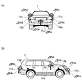
- FIG. 1A and FIG. 1B are explanatory diagrams showing the configuration of the driving support device 10.
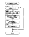
- FIG. 2 is a flowchart showing a composite image display process executed by the control device 13.
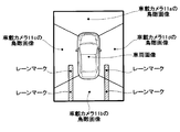
- FIG. 3 is an explanatory diagram illustrating a composite image in which no malfunction occurs.
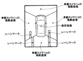
- FIG. 4 is an explanatory diagram illustrating a composite image in which a problem has occurred.
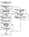
- FIG. 5 is a flowchart showing camera posture detection processing executed by the control device 13.
- 6 (a) and 6 (b) are explanatory diagrams conceptually showing the contents of postures of the in-vehicle cameras 11a to 11d.
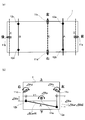
- FIGS. 7 (a) and 7 (b) are explanatory diagrams conceptually showing a method of detecting the roll change amount and the pitch change amount of the in-vehicle cameras 11a to 11d.
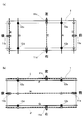
- FIGS. 8A and 8B are explanatory diagrams conceptually showing a method of detecting the roll change amount and the pitch change amount of the in-vehicle cameras 11a to 11d.
- 9 (a) and 9 (b) are explanatory diagrams conceptually showing a method of detecting the amount of change in roll and the amount of change in pitch of the in-vehicle cameras 11a to 11d when the vehicle 1 is not a rigid body.
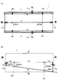
- FIG. 10 (a) and 10 (b) are explanatory diagrams conceptually showing a method of detecting the amount of change in the vertical position of the vehicle-mounted cameras 11a to 11d.
- FIG. 11 is a flowchart showing a camera posture detection process executed by the control device 13 in the modified example.
- FIG. 12 is a flowchart showing a camera posture detection process executed in addition.
- FIG. 1A and FIG. 1B show the configuration of the driving support device 10 provided in the vehicle 1.
- FIG. 1A conceptually shows the positions of the on-vehicle cameras 11a to 11d and the height sensors 12a to 12d that the driving support apparatus 10 has.
- vehicle-mounted cameras 11a to 11d are provided on the front, rear, left and right of the vehicle 1.
- These in-vehicle cameras 11a to 11d are mounted positions and mounting angles so as to photograph a little on the road surface (relative positions from the vehicle relative to each other) on the front, rear, left and right sides of the vehicle 1, respectively. Is adjusted.
- Height sensors 12a to 12d are provided on the left and right of the front portion and the left and right of the rear portion of the vehicle 1, respectively. These height sensors 12a to 12d can detect the vehicle height of the vehicle 1 at the position where it is attached.
- an indirect height sensor that uses the vertical displacement of the suspension arm with respect to the vehicle body, a direct height sensor that directly measures the distance from the road surface with ultrasonic waves or a laser, and the like can be used. .
- FIG. 1B conceptually shows the control device 13 that cooperates with the above-described in-vehicle cameras 11a to 11d and the height sensors 12a to 12d in the driving support device 10 of the present embodiment.
- the control device 13 includes a board on which a CPU, a memory, various controllers, and the like are mounted, and is installed on the back side of the instrument panel in front of the driver's seat.
- the control device 13 determines the vehicle height detected by the opening / closing detection unit 14 for detecting the opening and closing of the door and trunk of the vehicle 1 and the height sensors 12a to 12d. Based on the vehicle height detected by the height sensors 12a to 12d, the camera presence / absence detecting unit 15 for detecting that the attitude of the in-vehicle cameras 11a to 11d has changed by a predetermined amount or more, and the camera attitude for detecting the attitude of the in-vehicle cameras 11a to 11d The detection unit 16, the image viewpoint conversion unit 17 that performs viewpoint conversion (coordinate conversion) of each image around the vehicle taken by the in-vehicle cameras 11 a to 11 d into an image viewed from above the vehicle 1, and the combined images converted from the viewpoints are displayed. The image composition unit 18 displayed on the unit 30, the vehicle speed judgment unit 19 for judging the vehicle speed of the vehicle 1, and various data and programs are stored. And a storage unit 20 or the like to be.
- the liquid crystal display etc. which were provided in the instrument panel ahead of a driver's seat are employ
- the camera posture detection unit 16 corresponds to the “posture detection device” in the present disclosure
- the image viewpoint conversion unit 17 and the storage unit 20 correspond to the “acquisition device” in the present disclosure
- the image composition unit 18 and the display unit 30 correspond to “driving support execution device” in the present disclosure.
- the control device 13 corresponds to the “image correction device” in the present disclosure.
- FIG. 2 shows a flowchart of the composite image display process performed in the driving support device 10 of the present embodiment. Note that the processing performed in the driving support device 10 of this embodiment is actually performed by the CPU in the control device 13 executing a program stored in the ROM. The function blocks 14 to 20 will be described as the execution subject.
- the composite image display process is repeatedly performed as a timer interrupt process (for example, every 1/60 second) after the ACC power is turned on.
- the vehicle speed determination unit 19 of the control device 13 determines whether or not the vehicle 1 is traveling at a low speed (S100). For example, it is determined whether or not the vehicle speed is 10 km / h or less based on a vehicle speed pulse transmitted from a vehicle speed sensor (not shown). As a result of the determination process in S100, if it is determined that the vehicle 1 is not traveling at a low speed (S100: no), the combined image display process shown in FIG.
- the composite image display process shown in FIG. 2 is a process of displaying the status of the area near the vehicle 1 in the vicinity of the vehicle 1. Therefore, when the vehicle 1 is not traveling at a low speed, even if the situation of the area close to the vehicle 1 is displayed, the situation is instantaneously switched and does not become significant information for the driver.
- the image viewpoint conversion unit 17 captures images (hereinafter referred to as “captured images”) captured by the in-vehicle cameras 11a to 11d.
- the data is read from 11a to 11d and temporarily stored in the storage unit 20 (S102).
- the captured images stored in the storage unit 20 are respectively images (bird's-eye images) viewed from above the vehicle 1.
- Viewpoint conversion coordinate conversion
- the ideal postures used below are the design values for mounting the in-vehicle cameras 11a to 11d, and the postures at the time of shipment are actually measured values when the in-vehicle cameras 11a to 11d are mounted (at the time of shipment). This is a value indicating the attitude of the in-vehicle cameras 11a to 11d with respect to the vehicle.
- the actual posture temporary posture is a measured value of the posture of the in-vehicle cameras 11a to 11d after being changed by the load applied to the vehicle 1, and this is the posture of the in-vehicle cameras 11a to 11d with respect to the road surface. Is a value indicating
- the in-vehicle cameras 11a to 11d are kept in an ideal posture (design value) (for example, from an ideal roll or pitch). It is difficult to install (so that it does not deviate by 1 °). Therefore, before shipment of the vehicle 1, the shipping postures of the in-vehicle cameras 11a to 11d are stored in the storage unit 20 in advance.
- the viewpoint conversion process corresponding to the actual attitude of each of the in-vehicle cameras 11a to 11d (the viewpoint conversion process in consideration of the attitude at the time of shipment) is performed (in-vehicle camera 11a in each of the four directions of the vehicle 1).
- the image composition unit 18 displays an image obtained by combining these images (hereinafter referred to as “composite image”) on the display unit 30.
- composite image an image obtained by combining these images
- FIG. 3 shows an example of a composite image displayed in the process of S108.
- a “vehicle image when the vehicle 1 is viewed from above” is displayed at the center of the display unit 30, and a bird's-eye image of the in-vehicle camera 11 a is displayed in front of the vehicle image.
- the bird's-eye view image of the in-vehicle camera 11b is displayed behind the vehicle image
- the bird's-eye view image of the in-vehicle camera 11c is displayed to the left of the vehicle image
- the bird's-eye image of the in-vehicle camera 11d is displayed to the right of the vehicle image.
- the lane mark present on the left behind the vehicle 1 is reflected across the bird's-eye image of the in-vehicle camera 11b and the bird's-eye image of the in-vehicle camera 11c.
- the lane mark is displayed at the joint between the bird's-eye image of the in-vehicle camera 11b and the bird's-eye image of the in-vehicle camera 11c.
- the attitude of the in-vehicle cameras 11a to 11d (here, the in-vehicle cameras 11b and 11c) at the time of shipment is stored in the storage unit 20 before the vehicle 1 is shipped, and the viewpoint conversion process corresponding to the actual attitude is performed. This is because each bird's-eye view image is generated by performing the above.
- the lane mark present on the right rear of the vehicle 1 is reflected across the bird's-eye image of the in-vehicle camera 11b and the bird's-eye image of the in-vehicle camera 11d, the lane mark is connected at the joint between these bird's-eye images. Displayed without deviation.
- this also means that the actual postures of the in-vehicle cameras 11a to 11d (here, the in-vehicle cameras 11b and 11d) are stored in the storage unit 20 before the vehicle 1 is shipped, and the viewpoint conversion process corresponding to the actual posture is performed. This is because each bird's-eye view image is generated.
- the actual postures of the in-vehicle cameras 11a to 11d are stored in the storage unit 20 before the vehicle 1 is shipped, and the viewpoint conversion process corresponding to the actual posture is performed.
- image misalignment between the bird's-eye images obtained by the in-vehicle cameras 11a to 11d is prevented.
- the postures (actual postures) of the in-vehicle cameras 11a to 11d may change after the vehicle 1 is shipped.
- the load applied to the vehicle 1 changes to change the attitude of the vehicle 1, and accordingly, the in-vehicle cameras 11a to 11d.
- the posture also changes.
- image misalignment may occur between the bird's-eye images. For example, as shown in FIG.
- the lane mark reflected in the bird's-eye image of the in-vehicle camera 11c and the lane mark reflected in the bird's-eye image of the in-vehicle camera 11b are mutually the same lane mark although they are the same lane mark. There is a risk of being displayed with a deviation.
- the driving support device 10 of the present embodiment when it is detected that “a load applied to the vehicle 1 by a passenger to be boarded or a load to be loaded (hereinafter simply referred to as“ loading load ”)” is determined, the driving support device 10 changes depending on the load.
- the attitude of the vehicle 1 to be operated that is, the actual attitude of the in-vehicle cameras 11a to 11d is newly detected. That is, the postures of the in-vehicle cameras 11a to 11d stored in the storage unit 20 are corrected.
- “camera posture detection processing” for detecting (correcting) the actual postures of the in-vehicle cameras 11a to 11d as the “loading load” will be described. B-2.
- FIG. 5 shows a flowchart of a camera posture detection process performed in the driving support device 10 of the present embodiment. This camera posture detection process is repeatedly performed as a timer interruption process (for example, every 1/60 second) after the ACC power is turned on.
- the control device 13 When the camera posture detection process shown in FIG. 5 is started, the control device 13 first determines whether or not the load confirmed flag is set to ON (S200).
- the load confirmed flag is a flag indicating that the above-described “load applied to the vehicle 1 by a passenger to be boarded or a load to be loaded (loaded load)” has already been confirmed, and is stored in a predetermined address of the storage unit 20. A storage area is reserved. Accordingly, in the determination process of S200, it is naturally determined whether or not the “loading load” has already been determined.
- the open / close detection unit 14 determines whether the door or trunk of the vehicle 1 is open.
- (Opening / closing information) is read out (S202). For example, an “open / close signal” transmitted from a sensor that detects opening / closing of a door or trunk such as a courtesy switch is received. Based on the opening / closing signal, information (opening / closing information) indicating whether the door or the trunk is open is read out. Thus, when the opening / closing information is read (S202), it is determined whether all the doors and trunks of the vehicle 1 are closed based on the opening / closing information (S204).
- the part 15 determines. Specifically, the vehicle heights detected by the height sensors 12a to 12d (at the respective positions) are read out, and these vehicle heights are stored in the storage unit 20 (S208). Then, “the vehicle height read this time” and “the vehicle height at the time when the actual postures of the in-vehicle cameras 11a to 11d were previously detected (corrected)” are compared for the respective height sensors 12a to 12d (S210).
- a predetermined threshold ⁇ Sth S210: yes
- the posture of the vehicle 1 also changes to some extent, and accordingly, the in-vehicle cameras 11a to 11d. It is determined that the actual posture has also changed more than a predetermined amount.
- the camera posture detection unit 16 detects the vehicles detected by the height sensors 12a to 12d. By detecting the current posture of the vehicle based on the height, the actual postures of the current in-vehicle cameras 11a to 11d are detected (S212). Then, the detected actual postures of the in-vehicle cameras 11a to 11d are stored in the storage unit 20. As a result, the actual postures of the in-vehicle cameras 11a to 11d reflected (considered) in the viewpoint conversion process (S104) in FIG. 2 are corrected. The process of detecting the actual postures of the on-vehicle cameras 11a to 11d (S212) will be described in detail later.
- the driving support device 10 detects the actual postures of the in-vehicle cameras 11a to 11d based on the detection results of the height sensors 12a to 12d, so that it corresponds to the “loading load” applied to the vehicle 1. It is possible to detect the actual postures of the in-vehicle cameras 11a to 11d that change. Since the viewpoint conversion processing corresponding to the actual postures of the in-vehicle cameras 11a to 11d is performed, it is possible to eliminate the image shift at the joint between the bird's-eye images in the composite image.
- the driving support device 10 of this embodiment estimates that the “loading load”, that is, the actual postures of the in-vehicle cameras 11a to 11d is determined when all the doors and trunks of the vehicle 1 are closed, and the in-vehicle camera The actual postures 11a to 11d are detected. Accordingly, since the actual postures of the in-vehicle cameras 11a to 11d can be detected at the timing when the actual postures of the in-vehicle cameras 11a to 11d are determined, the in-vehicle cameras 11a to 11d are reduced while reducing the processing load on the control device 13. It is possible to appropriately eliminate the image shift at the joint between the bird's-eye images due to the posture change.
- the device 10 need not include a specific object such as a lane mark in the image.
- the opening / closing detection unit 14 detects the door of the vehicle 1 And information on whether the trunk is open (opening / closing information) is read (S214). Based on the opening / closing information, it is determined whether or not at least one of the door and the trunk of the vehicle 1 is opened (S216).
- the door is opened again and passengers get on and off, or the trunk is opened again.
- the “loading load” may change (as a result, the posture of the vehicle 1 may change and the actual posture of the in-vehicle cameras 11a to 11d may also change). Therefore, when at least one of the door and the trunk of the vehicle 1 is opened (S216: yes), the “loading load” is to be determined until all the doors and the trunk of the vehicle 1 are closed again. Then, the load confirmed flag is set to OFF (S218).
- the camera posture detection process shown in FIG. 5 is terminated.
- the processing of S204 to S212 described above is executed. That is, when the “loading load” is determined by closing all the doors and trunks of the vehicle 1, the actual postures of the in-vehicle cameras 11a to 11d are detected. Then, in the composite image display process (FIG. 2) executed after the actual postures of the in-vehicle cameras 11a to 11d are detected, viewpoint conversion processing corresponding to the detected actual postures of the in-vehicle cameras 11a to 11d is performed. (S104 in FIG. 2).
- the driving support device 10 is closed once the door or the trunk of the vehicle 1 is opened again even after the actual posture of the in-vehicle camera is detected. Then, it is estimated that there is a change in the “loading load”, that is, the actual postures of the in-vehicle cameras 11a to 11d, and the actual postures of the in-vehicle cameras 11a to 11d are detected again. Therefore, since the postures can be detected at the timing when the actual postures of the in-vehicle cameras 11a to 11d change, the image at the joint between the bird's-eye images in the composite image is reduced while reducing the processing load on the control device 13. It is possible to eliminate the deviation. B-3.
- Detecting the actual posture of the in-vehicle camera Next, a method for detecting (calculating) the actual postures of the in-vehicle cameras 11a to 11d based on the vehicle heights detected by the height sensors 12a to 12d, that is, the contents of S212 in the camera posture detection process shown in FIG. .
- the change amount of the roll, the change amount of the pitch, and the change amount of the vertical position from the posture before shipment are detected. That is, as shown in FIGS. 6A and 6B, in the case of the in-vehicle cameras 11a and 11b provided at the front and rear, the amount of change in the rotation angle (pitch) about the horizontal direction of the vehicle 1 ( ⁇ Pa, ⁇ Pb), changes in rotation angle (roll) ( ⁇ Ra, ⁇ Rb (not shown)), and changes in vertical position ( ⁇ Ha, ⁇ Hb) about the longitudinal direction of the vehicle 1 are detected.
- the amount of change ( ⁇ Pc, ⁇ Pd) of the rotation angle (pitch) about the front-rear direction of the vehicle 1 and the rotation angle about the left-right direction of the vehicle 1 (Roll) change amounts ( ⁇ Rc (not shown), ⁇ Rd) and vertical position change amounts ( ⁇ Hc, ⁇ Hd) are detected.
- various methods can be adopted as a method of detecting these changes.
- On-vehicle camera roll change and pitch change detection methods 7 (a), 7 (b), 8 (a), and 8 (b) conceptually show a method for detecting the amount of change in roll and the amount of change in pitch of the in-vehicle cameras 11a to 11d.
- FIGS. 7A and 7B and FIGS. 8A and 8B the vehicle 1 is simplified (in a rectangular shape) for easy understanding.
- the amount of change in the pitch of the virtual axis A (or the virtual axis B passing through the height sensors 12c and 12d) passing through the height sensors 12a and 12b and the in-vehicle cameras 11c and 11d shown in FIG.
- the amount of change in the pitch of the imaginary axis C that passes through is the same. Accordingly, by calculating the amount of change in the pitch of the virtual axis A (or virtual axis B), the amount of change in the pitch ( ⁇ Pc, ⁇ Pd) of the in-vehicle cameras 11c and 11d can be calculated.
- the amount of change in the pitch of the virtual axis A passing through the height sensors 12a and 12b (or the virtual axis B passing through the height sensors 12c and 12d) and the amount of change in the pitch of the virtual axis D passing through the in-vehicle camera 11a are the same. Further, the amount of change in the pitch of the virtual axis A (or virtual axis B) and the amount of change in the pitch of the virtual axis E passing through the in-vehicle camera 11b coincide.
- the amount of change in the pitch of the virtual axis A (or virtual axis B)
- the amount of change in the roll ( ⁇ Ra, ⁇ Rb) of the in-vehicle cameras 11a, 11b can also be calculated.
- the amount of change in the pitch of the virtual axis A (or virtual axis B) is also the amount of change in the roll of the vehicle 1 itself (the posture of the vehicle). Therefore, this amount of change is represented as ⁇ CarR below.
- the pitch change amount of the virtual axis A (or virtual axis B) (the change amount ⁇ CarR of the roll of the vehicle 1 itself) is between the left and right height sensors 12a-12b (12c-12d). Is obtained by the following equation using the distance (Y1) in the left-right direction, the change amount ( ⁇ Sa) of the vehicle height detected by the height sensor 12a, and the change amount ( ⁇ Sb) of the vehicle height detected by the height sensor 12b. be able to.
- ⁇ CarR arctan (Y1 /
- the amount of change in the pitch of the virtual axis A (or virtual axis B) thus determined is, as described above, the amount of change in the pitch of the in-vehicle cameras 11c and 11d ( ⁇ Pc, ⁇ Pd) and the amount of change ( ⁇ Ra, ⁇ Rb) of the in-vehicle cameras 11a, 1b.
- the amount of change in the pitch of the virtual axis F that passes through the height sensors 12a and 12c matches the amount of change in the pitch of the virtual axis I that passes through the in-vehicle camera 11c. Further, the amount of change in the pitch of the virtual axis F (or virtual axis G) and the amount of change in the pitch of the virtual axis J passing through the in-vehicle camera 11d coincide.
- the amount of change in the pitch of the virtual axis F (or virtual axis G)
- the amount of change in the roll ( ⁇ Rc, ⁇ Rd) of the in-vehicle cameras 11c, 11d can be calculated.
- the amount of change in the pitch of the virtual axis F (or virtual axis G) is also the amount of change in the pitch of the vehicle 1 itself (the attitude of the vehicle). Therefore, this amount of change is represented as ⁇ CarP below.
- the amount of change in the pitch of the virtual axis F (or virtual axis G) (the amount of change ⁇ CarP in the vehicle 1 itself) is between the front and rear height sensors 12b-12d (12a-12c). Is obtained by the following equation using a distance (Y2) in the front-rear direction of the vehicle, a change amount ( ⁇ Sb) of the vehicle height detected by the height sensor 12b, and a change amount ( ⁇ Sd) of the vehicle height detected by the height sensor 12d. be able to.
- ⁇ CarP arctan (Y2 /
- the amount of change in the pitch of the virtual axis F (or virtual axis G) thus determined is, as described above, the amount of change in the pitch of the in-vehicle cameras 11a and 11b ( ⁇ Pa, ⁇ Pb) and the amount of change ( ⁇ Rc, ⁇ Rd) of the in-vehicle cameras 11c, 11d.
- the calculation results of the above formulas (1) and (2) may not match the rolls and pitches of the in-vehicle cameras 11a to 11d. That is, when the vehicle 1 is deformed by a load, twisting occurs, and the pitch of the virtual axis A (or virtual axis B) may not match the pitch of the virtual axes C to E.
- the pitch of the virtual axis A (or virtual axis B), the amount of change in the pitch of the in-vehicle cameras 11c and 11d ( ⁇ Pc, ⁇ Pd), and the amount of change in the roll of the in-vehicle cameras 11a and 11b ( ⁇ Ra , ⁇ Rb).
- the pitch of the virtual axis F (or virtual axis G) may not match the pitch of the virtual axes H to J.
- the pitch of the virtual axis F (or virtual axis G), the amount of change in the pitch of the in-vehicle cameras 11a and 11b ( ⁇ Pa, ⁇ Pb), and the amount of change in the roll of the in-vehicle cameras 11c and 11d ( ⁇ Rc) , ⁇ Rd).
- each specific position is determined based on the amount of change in vehicle height detected by each height sensor 12a to 12d and the distance (in the horizontal direction) from each height sensor 12a to 12d to each specific position (marked in the figure).
- the amount of change in the vehicle height at is calculated.
- Y1 and Y2 in the equations (1) and (2) are replaced with “distances (in the horizontal direction) between specific positions on the same virtual axis”, and ⁇ Sa, ⁇ Sb, and ⁇ Sd are replaced with “the vehicle height at each specific position.
- the pitches of the virtual axes C to E and H to J are calculated, and the calculated pitches of the virtual axes C to E and H to J are approximated by the in-vehicle cameras 11a to 11d.
- the amount of change in roll or pitch is calculated.
- the virtual axis C A method of approximately calculating the pitches of E to E may be adopted, or the virtual axis H is based on the pitches of the virtual axes F and G and the distances from the virtual axes F and G to the virtual axes H to J. A method of approximately calculating the pitch of ⁇ I may be adopted. B-3-2. How to detect the change in the vertical position of the in-vehicle camera: FIGS.
- 10A and 10B conceptually show a method of detecting the change amounts ⁇ Ha and ⁇ Hb of the vertical positions of the front and rear vehicle-mounted cameras 11a and 11b.
- the position (coordinates) in the front-rear direction on the virtual axis H is the same position as the height sensors 12a, 12b, and the position (coordinates) in the front-rear direction on the virtual axis H is the same position as the height sensors 12c, 12d.
- the amount of change in the vertical position at this specific position can be calculated based on the positional relationship between the in-vehicle cameras 11a and 11b and the height sensors 12a to 12d in the horizontal direction. For example, when the vehicle-mounted camera 11a is in the middle of the height sensors 12a and 12b in the left-right direction, the vertical position change amount ⁇ Sab at the specific position can be calculated as an average of the detection results of the height sensors 12a and 12b.
- the in-vehicle camera 11a in the virtual axis H is calculated.
- the amount of change in the vehicle height (thick line arrow in the figure) that is, the amount of change ⁇ Ha, ⁇ Hb in the vertical position of the in-vehicle cameras 11a, 11b) is calculated.
- This amount of change is obtained by using a similar relationship, the distance Y2 between the height sensors 12b-12d (or between the height sensors 12a-12c) in the front-rear direction, and from the in-vehicle camera 11a to the height sensor 12b (or the height sensor 12a).
- the distance Y3 in the front-rear direction the distance Y4 in the front-rear direction from the vehicle-mounted camera 11b to the height sensor 12d (or height sensor 12c), and the vehicle height changes ⁇ Sab, ⁇ Scd at a specific position
- calculation is performed based on the similarity relationship. . That is, in the example shown in FIG. 10B, it can be calculated by the following equations (3) and (4).
- FIG. 11 shows a flowchart of camera posture detection processing in the modification.
- the process of S300 in FIG. 11 is added to the camera posture detection process of the above-described embodiment (FIG. 5).
- the actual postures of the in-vehicle cameras 11a to 11d are detected on the assumption that the load (loading load) applied to the vehicle 1 is determined when all the doors and the trunk are closed.
- the load (loading load) applied to the vehicle 1 is determined, and the in-vehicle camera 11a
- the following effects can be produced.
- the load applied to the vehicle 1 may be determined. Since the actual postures of the in-vehicle cameras 11a to 11d can be detected after becoming larger, the processing load on the control device 13 can be further reduced.
- a camera posture detection process as shown in FIG. 12 may be performed. That is, when the ACC power is turned on (S300: yes), or when the vehicle 1 starts running regardless of whether all the doors and trunks are closed (S304: yes), the in-vehicle cameras 11a to 11 The actual posture of 11d may be detected (S302, S306). In this way, the actual postures of the in-vehicle cameras 11a to 11d can be detected more reliably.
- the present disclosure is not limited to the above-described embodiment and modified example, and can be implemented in various modes without departing from the gist thereof.
- the arithmetic processing can be simplified (the height sensor value is directly used as the amount of change in the vertical position of the in-vehicle cameras 11a to 11d).
- the camera posture detection unit 16 is configured such that when all the doors and trunks are closed, or when all the doors and trunks are closed and the vehicle 1 starts to travel. In addition, it is estimated that the load applied to the vehicle 1 has been determined, and the actual postures of the in-vehicle cameras 11a to 11d are detected. However, the present invention is not limited to this, and the camera posture detection unit 16 may detect the actual postures of the in-vehicle cameras 11a to 11d when the vehicle 1 simply starts to travel.
- the camera posture detection unit 16 estimates that the load applied to the vehicle 1 is fixed when the brake pedal that has been depressed returns to the state before the depression, or when the side brake is released, The actual postures of the cameras 11a to 11d may be detected. In such a case, it can be estimated that the brake has been released immediately before the start of traveling, so that it is unlikely that the occupant will subsequently board or load the cargo, and consequently the load applied to the vehicle 1 There is a high possibility of being confirmed. Therefore, if the actual postures of the in-vehicle cameras 11a to 11d are detected when the brake is released, the actual load of the in-vehicle cameras 11a to 11d is increased after the possibility that the load applied to the vehicle 1 has been determined becomes greater. Since the posture can be detected, the processing load on the control device 13 can be further reduced.
- the driving support is executed by displaying a composite image obtained by connecting bird's-eye images.
- the present invention is not limited to this, and an image captured by the in-vehicle camera may be corrected based on the actual posture of the in-vehicle camera (vehicle), and the positional relationship between the vehicle and the lane mark may be detected based on the corrected image. . Even if the vehicle lane departure is monitored from the positional relationship between the vehicle and the lane mark, and when the lane departure is detected, a warning is output or the steering is automatically controlled to execute driving support. Good.
Landscapes
- Engineering & Computer Science (AREA)
- Multimedia (AREA)
- Signal Processing (AREA)
- Physics & Mathematics (AREA)
- General Physics & Mathematics (AREA)
- Mechanical Engineering (AREA)
- Theoretical Computer Science (AREA)
- Closed-Circuit Television Systems (AREA)
- Traffic Control Systems (AREA)
- Image Analysis (AREA)
Abstract
運転支援装置は、車載カメラ(11a~11d)が所定の角度で取り付けられた車両(1)に設けられて、前記車載カメラが撮影した画像に基づいて運転支援を実行する。前記運転支援装置は、前記車両の複数箇所に取り付けられて、取り付けられた箇所での車高を検出するハイトセンサー(12a~12d)と、前記ハイトセンサーの検出結果に基づいて前記車両の姿勢を検出する姿勢検出装置(16)と、前記画像を取得する取得装置(17、20)と、前記取得装置が取得した前記画像を、前記車両の姿勢に基づいて補正する補正装置(17)と、補正された前記画像に基づいて、運転支援を実行する実行装置(18、30)とを備える。
Description
本開示は、2014年6月18日に出願された日本出願番号2014-124874号に基づくもので、ここにその記載内容を援用する。
本開示は、車載カメラで撮影された画像に基づいて運転を支援する技術に関する。
車載カメラで車両周辺を撮像し、その画像に基づいて運転支援を実行する技術が知られている。例えば、道路上に描かれたレーンマークを車載カメラで撮影することによって車両の車線逸脱を監視し、該車線逸脱が検出された場合はその旨を運転者に報知する技術や、複数の車載カメラを互いに異なる方向に向けて設置し、複数の車載カメラが撮影したそれぞれの画像を車両上方から見た複数の鳥瞰画像に変換すると共に互いに繋ぎ合わせて表示することで、車両の周辺を上方から見た画像を表示する技術(例えば、特許文献1)等が存在する。
このような技術においては、車載カメラによってレーンマークや他車両等の対象物が撮影されると、その撮影画像内における対象物の位置(画像内位置)に基づいて、運転支援を実行する。従って、当然ながら、車両からの相対位置のうち予め定められた相対位置を撮影した画像が必要となる。そこで、車載カメラの取り付け位置や取り付け角度(姿勢)は、予め定められた相対位置が撮影されるように、前もって調節されている。
しかし、上述した従来技術では、車載カメラの姿勢を前もって調節しても、予め定められた相対位置が撮影されず、運転支援を適切に行うことができないという問題があった。すなわち、車載カメラの姿勢の調節を行った後であっても、乗員が搭乗したり荷物を積載したりすることで車両にかかる荷重が変化すると、車両の姿勢が変化し、これに伴って、車載カメラの姿勢も変化してしまう。このような場合は、予め定められた相対位置が撮影されなくなってしまうので、運転支援を適切に行うことができないという問題があった。
本開示は、車載カメラの画像に基づく運転支援を適切に実行することができる技術の提供を目的とする。
上記目的を達成するため、本開示の第一の態様において、運転支援装置は、車載カメラが所定の角度で取り付けられた車両に設けられて、前記車載カメラが撮影した画像に基づいて運転支援を実行する。前記運転支援装置は、前記車両の複数箇所に取り付けられて、取り付けられた箇所での車高を検出するハイトセンサーと、前記ハイトセンサーの検出結果に基づいて前記車両の姿勢を検出する姿勢検出装置と、前記車載カメラが撮影した画像を取得する取得装置と、前記取得装置が取得した前記画像を、前記姿勢検出装置が検出した前記車両の姿勢に基づいて補正する補正装置と、前記補正装置によって補正された前記画像に基づいて、運転支援を実行する実行装置とを備える。
本開示の第二の態様において、運転支援方法では、車両に所定の角度で取り付けられた車載カメラが撮影した画像に基づいて運転支援を実行する。前記運転支援方法では、ハイトセンサーの検出結果に基づいて車両の姿勢を検出し、前記車載カメラが撮影した画像を取得し、取得した前記画像を、前記車両の姿勢に基づいて補正し、補正された前記画像に基づいて、運転支援を実行する。
本開示の第三の態様において、画像補正装置は、車載カメラが所定の角度で取り付けられた車両に設けられて、前記車載カメラが撮影した画像を補正する。前記画像補正装置は、前記車両の複数箇所に取り付けられて、取り付けられた箇所での車高を検出するハイトセンサーと、前記ハイトセンサーの検出結果に基づいて前記車両の姿勢を検出する姿勢検出装置と、前記車載カメラが撮影した画像を取得する取得装置と、前記取得装置が取得した前記画像を、前記姿勢検出装置が検出した前記車両の姿勢に基づいて補正する補正装置とを備える。
本開示の第四の態様において、画像補正方法では、車両に所定の角度で取り付けられた車載カメラが撮影した画像を補正する。前記画像補正方法では、ハイトセンサーの検出結果に基づいて車両の姿勢を検出し、前記車載カメラが撮影した画像を取得し、取得した前記画像を、前記車両の姿勢に基づいて補正する。
本開示の第一の態様と第三の態様とに係る装置、および、本開示の第二の態様と第四の態様とに係る方法によれば、ハイトセンサーの検出結果に基づいて車両の姿勢を検出するので、車両にかかる荷重に応じて変化する車両の姿勢(ひいては車載カメラの姿勢)を検出することができる。そして、この車両の姿勢に基づいて車載カメラで撮影された画像を補正して、この補正された画像に基づいて運転支援を実行する。従って、車載カメラの画像に基づく運転支援を適切に実行することが可能となる。
本開示についての上記目的およびその他の目的、特徴や利点は、添付の図面を参照しながら下記の詳細な記述により、より明確になる。その図面は、
図1(a)及び図1(b)は、運転支援装置10の構成を示す説明図であり、
図2は、制御装置13によって実行される合成画像表示処理を示すフローチャートであり、
図3は、不具合の生じていない合成画像を例示する説明図であり、
図4は、不具合の生じた合成画像を例示する説明図であり、
図5は、制御装置13によって実行されるカメラ姿勢検出処理を示すフローチャートであり、
図6(a)及び図6(b)は、車載カメラ11a~11dの姿勢の内容を概念的に示す説明図であり、
図7(a)及び図7(b)は、車載カメラ11a~11dのロールの変化量、ピッチの変化量を検出する方法を概念的に示す説明図であり、
図8(a)及び図8(b)は、車載カメラ11a~11dのロールの変化量、ピッチの変化量を検出する方法を概念的に示す説明図であり、
図9(a)及び図9(b)は、車両1が剛体でない場合における車載カメラ11a~11dのロールの変化量、ピッチの変化量を検出する方法を概念的に示す説明図であり、
図10(a)及び図10(b)は、車載カメラ11a~11dの上下位置の変化量を検出する方法を概念的に示す説明図であり、
図11は、変形例における制御装置13によって実行されるカメラ姿勢検出処理を示すフローチャートであり、
図12は、加えて実行されるカメラ姿勢検出処理を示すフローチャートである。
以下では、上述した本願発明の内容を明確にするために運転支援装置の実施例について説明する。
A.装置構成 :
図1(a)及び図1(b)には、車両1に設けられた運転支援装置10の構成が示されている。なかでも、図1(a)には、運転支援装置10が有する車載カメラ11a~11dおよびハイトセンサー12a~12dの配設位置が概念的に示されている。図1(a)に示すように、本実施例の運転支援装置10では、車両1の前後左右に車載カメラ11a~11dが設けられている。これらの車載カメラ11a~11dは、それぞれ車両1の前方、後方、左方、右方のやや路面側(車両からの相対位置のうち、互いに異なる相対位置)を撮影するように取り付け位置および取り付け角度が調節されている。また、車両1の前部の左右および後部の左右には、ハイトセンサー12a~12dが設けられている。これらのハイトセンサー12a~12dは、それぞれ自己が取り付けられた位置における車両1の車高を検出することが可能である。尚、ハイトセンサー12a~12dとしては、車体に対するサスペンションアームの上下変位量を用いる間接式ハイトセンサーや、路面との距離を超音波やレーザーで直接計測する直接式ハイトセンサー等を利用することができる。
A.装置構成 :
図1(a)及び図1(b)には、車両1に設けられた運転支援装置10の構成が示されている。なかでも、図1(a)には、運転支援装置10が有する車載カメラ11a~11dおよびハイトセンサー12a~12dの配設位置が概念的に示されている。図1(a)に示すように、本実施例の運転支援装置10では、車両1の前後左右に車載カメラ11a~11dが設けられている。これらの車載カメラ11a~11dは、それぞれ車両1の前方、後方、左方、右方のやや路面側(車両からの相対位置のうち、互いに異なる相対位置)を撮影するように取り付け位置および取り付け角度が調節されている。また、車両1の前部の左右および後部の左右には、ハイトセンサー12a~12dが設けられている。これらのハイトセンサー12a~12dは、それぞれ自己が取り付けられた位置における車両1の車高を検出することが可能である。尚、ハイトセンサー12a~12dとしては、車体に対するサスペンションアームの上下変位量を用いる間接式ハイトセンサーや、路面との距離を超音波やレーザーで直接計測する直接式ハイトセンサー等を利用することができる。
また、図1(b)には、本実施例の運転支援装置10において、上述した車載カメラ11a~11dおよびハイトセンサー12a~12dと連携する制御装置13が概念的に示されている。制御装置13は、CPUやメモリ、各種コントローラー等が搭載された基板を有しており、運転席前方のインストルメントパネルの奥側に設置されている。
制御装置13内部をそれぞれの機能を有する機能ブロックに分類すると、制御装置13は、車両1のドアやトランクの開放および閉鎖を検出する開閉検出部14、ハイトセンサー12a~12dが検出する車高に基づいて車載カメラ11a~11dの姿勢が所定量以上変化したことを検出する変化有無検出部15、ハイトセンサー12a~12dが検出する車高に基づいて車載カメラ11a~11dの姿勢を検出するカメラ姿勢検出部16、車載カメラ11a~11dが撮影した車両周辺の画像それぞれを車両1上方から見た画像に視点変換(座標変換)する画像視点変換部17、それぞれ視点変換された画像を合成して表示部30に表示する画像合成部18、車両1の車速を判断する車速判断部19、種々のデータやプログラム等が記憶される記憶部20等から構成される。
尚、表示部としては、運転席前方のインストルメントパネルに設けられた液晶表示器等が採用される。また、カメラ姿勢検出部16が本開示における「姿勢検出装置」に対応し、画像視点変換部17および記憶部20が本開示における「取得装置」に対応し、画像視点変換部17が本開示における「補正装置」に対応し、画像合成部18および表示部30が本開示における「運転支援実行装置」に対応している。また、制御装置13が本開示における「画像補正装置」に対応している。
次に、上述したような運転支援装置10において行われる処理について説明する。以下では、先ず、車両1の周辺状況を上方から見た画像(合成画像)を表示部30に表示する「合成画像表示処理」について説明する。
B.運転支援装置10において行われる処理 :
B-1.合成画像表示処理 :
図2には、本実施例の運転支援装置10において行われる合成画像表示処理のフローチャートが示されている。尚、本実施例の運転支援装置10において行われる処理は、実際には、制御装置13内部のCPUがROMに記憶されたプログラムを実行することによって行われるが、以下では、制御装置13または上述した機能ブロック14~20を実行主体として説明する。また、合成画像表示処理は、ACC電源が投入された後、タイマ割り込み処理として(例えば60分の1秒毎に)繰り返し行われる。
B.運転支援装置10において行われる処理 :
B-1.合成画像表示処理 :
図2には、本実施例の運転支援装置10において行われる合成画像表示処理のフローチャートが示されている。尚、本実施例の運転支援装置10において行われる処理は、実際には、制御装置13内部のCPUがROMに記憶されたプログラムを実行することによって行われるが、以下では、制御装置13または上述した機能ブロック14~20を実行主体として説明する。また、合成画像表示処理は、ACC電源が投入された後、タイマ割り込み処理として(例えば60分の1秒毎に)繰り返し行われる。
図2に示す合成画像表示処理を開始すると、制御装置13の車速判断部19は、車両1が低速走行中であるか否かを判断する(S100)。例えば、車速センサー(図示省略)から送信される車速パルスに基づいて、車速が10Km/h以下であるか否かを判断する。S100の判断処理の結果、車両1が低速走行中でないと判断された場合は(S100:no)、そのまま図2に示す合成画像表示処理を終了する。ここで、図2に示す合成画像表示処理は、車両1の周辺のうち車両1に近接した領域の状況を表示する処理である。従って、車両1が低速走行中でない場合は、車両1に近接した領域の状況を表示しても、該状況は瞬時に切り換わってしまい、運転者に有意な情報とならないので、そのまま図2に示す合成画像表示処理を終了する。
これに対して、車両1が低速走行中である場合は(S100:yes)、画像視点変換部17は、車載カメラ11a~11dそれぞれが撮影した画像(以下、「撮影画像」という)を車載カメラ11a~11dから読み出して、一旦、記憶部20に記憶する(S102)。そして、車載カメラ11a~11dの姿勢に対応させて(車載カメラ11a~11dの姿勢を考慮して)、記憶部20に記憶された撮影画像をそれぞれ車両1上方から見た画像(鳥瞰画像)に視点変換(座標変換)する(S104)。
尚、以下で利用する理想的な姿勢とは車載カメラ11a~11dの取り付け設計値であり、出荷時の姿勢とは車載カメラ11a~11dの取り付け時(出荷時)の実測値であり、これらは車載カメラ11a~11dの車両に対する姿勢を示す値である。これに対して、実際の姿勢(テンポラリーな姿勢)とは、車両1にかかる荷重によって変化した後の車載カメラ11a~11dの姿勢の実測値であり、これは車載カメラ11a~11dの路面に対する姿勢を示す値である。
車両1の出荷前には車載カメラ11a~11dの取り付け位置や取り付け角度は調節されているものの、車載カメラ11a~11dを理想的な姿勢(設計値)で(例えば、理想的なロールやピッチから1°たりともずれないように)取り付けることは困難である。そこで、車両1の出荷前には、車載カメラ11a~11dそれぞれの出荷時の姿勢が記憶部20に予め記憶されている。そして、S104の処理では、車載カメラ11a~11dそれぞれの実際の姿勢に対応する視点変換処理(出荷時の姿勢を考慮した視点変換処理)を行うことで、車両1の四方それぞれにおける(車載カメラ11a~11dそれぞれに対応する)鳥瞰画像を生成する。こうして、車両1の四方それぞれにおける鳥瞰画像を生成したら(S104)、画像合成部18は、これらの画像を合成した画像(以下「合成画像」という)を表示部30に表示する。こうして、合成画像を表示部30に表示したら、図2に示す合成画像表示処理を終了する。
図3には、S108の処理で表示される合成画像の一例が示されている。図3に示すように、本実施例の合成画像では、表示部30の中心に「車両1を上方から見た車両画像」が表示され、車両画像の前方に車載カメラ11aの鳥瞰画像が表示され、車両画像の後方に車載カメラ11bの鳥瞰画像が表示され、車両画像の左方に車載カメラ11cの鳥瞰画像が表示され、車両画像の右方に車載カメラ11dの鳥瞰画像が表示される。
図3に示す合成画像の例では、車両1後方の左に存在するレーンマークが、車載カメラ11bの鳥瞰画像および車載カメラ11cの鳥瞰画像に跨がって写り込んでいる。とはいえ、この合成画像の例では、車載カメラ11bの鳥瞰画像と車載カメラ11cの鳥瞰画像とのつなぎ目でレーンマークがズレることなく表示されている。これは、上述したように、車両1出荷前に車載カメラ11a~11d(ここでは車載カメラ11b,11c)の出荷時の姿勢が記憶部20に記憶され、該実際の姿勢に対応する視点変換処理を行うことで、それぞれの鳥瞰画像を生成したためである。
同様に、車両1後方の右に存在するレーンマークも、車載カメラ11bの鳥瞰画像および車載カメラ11dの鳥瞰画像に跨がって写り込んでいるものの、これらの鳥瞰画像同士のつなぎ目でレーンマークがズレることなく表示されている。もちろん、これも、車両1出荷前に車載カメラ11a~11d(ここでは車載カメラ11b,11d)の実際の姿勢が記憶部20に記憶され、該実際の姿勢に対応する視点変換処理を行うことで、それぞれの鳥瞰画像を生成したためである。
以上のように本実施例の運転支援装置10では、車両1出荷前に車載カメラ11a~11dの実際の姿勢が記憶部20に記憶され、該実際の姿勢に対応する視点変換処理を行うことで、車載カメラ11a~11dによる鳥瞰画像同士で画像のズレが生じないようにしている。もっとも、車両1出荷前の車載カメラ11a~11dの出荷時の姿勢が記憶されていたとしても、車両1出荷後に車載カメラ11a~11dの姿勢(実際の姿勢)が変化することがある。すなわち、車両1の出荷後に、車両1に乗員が搭乗したり荷物が積載されたりすると、車両1にかかる荷重が変化することで車両1の姿勢は変化し、それに伴って、車載カメラ11a~11dの姿勢も変化する。このように車載カメラ11a~11dの姿勢が変化したにも拘わらず、車両1出荷前に記憶された車載カメラ11a~11dの出荷時の姿勢に対応する鳥瞰画像を生成すると、車載カメラ11a~11dの鳥瞰画像同士で画像のズレが生じてしまう虞がある。例えば、図4に示すように、車載カメラ11cの鳥瞰画像に写り込んだレーンマークと、車載カメラ11bの鳥瞰画像に写り込んだレーンマークとが、同一のレーンマークであるにも拘わらず、互いにズレて表示されてしまう虞がある。
そこで、本実施例の運転支援装置10では、「搭乗する乗員や積載される荷物によって車両1にかかる荷重(以下、単に「積載荷重」という)」が確定したことを検出すると、該荷重によって変化する車両1の姿勢、すなわち、車載カメラ11a~11dの実際の姿勢を新たに検出する。すなわち、記憶部20に記憶されている車載カメラ11a~11dの姿勢を補正する。以下では、「積載荷重」が確定したことに伴って、車載カメラ11a~11dの実際の姿勢を検出(補正)する「カメラ姿勢検出処理」について説明する。
B-2.カメラ姿勢検出処理 :
図5には、本実施例の運転支援装置10において行われるカメラ姿勢検出処理のフローチャートが示されている。このカメラ姿勢検出処理は、ACC電源が投入された後、タイマ割り込み処理として(例えば60分の1秒毎に)繰り返し行われる。
B-2.カメラ姿勢検出処理 :
図5には、本実施例の運転支援装置10において行われるカメラ姿勢検出処理のフローチャートが示されている。このカメラ姿勢検出処理は、ACC電源が投入された後、タイマ割り込み処理として(例えば60分の1秒毎に)繰り返し行われる。
図5に示すカメラ姿勢検出処理を開始すると、制御装置13は先ず、荷重確定済フラグがONに設定されているか否かを判断する(S200)。荷重確定済フラグは、上述の「搭乗する乗員や積載される荷物によって車両1にかかる荷重(積載荷重)」が既に確定済みであることを示すフラグであって、記憶部20の所定アドレスにその記憶領域が確保されている。従って、S200の判断処理では、当然ながら、「積載荷重」が既に確定済みであるか否かが判断される。
S200の判断処理の結果、「積載荷重」が未だ確定済みでないと判断された場合は(S200:no)、続いて、開閉検出部14が、車両1のドアやトランクが開放しているか否かの情報(開閉情報)を読み出す(S202)。例えば、カーテシスイッチ等のドアやトランクの開閉を検出するセンサーから送信される「開閉信号」を受信する。そして、この開閉信号に基づいて、ドアやトランクが開放しているか否かの情報(開閉情報)を読み出す。こうして、開閉情報を読み出したら(S202)、該開閉情報に基づいて、車両1のドアおよびトランクの全てが閉鎖されたか否かを判断する(S204)。
S204の判断処理の結果、車両1のドアおよびトランクが未だ全ては閉鎖されていないと(何れかが開放されていると)判断された場合は(S204:no)、S202およびS204の処理を繰り返す。すなわち、車両1のドアおよびトランクの全てが閉鎖されるまで待機する。
そして、車両1のドアおよびトランクの全てが閉鎖された場合は(S204:yes)、荷重確定済フラグをONに設定する(S206)。
ここで、車両1のドアおよびトランクの全てが閉鎖された場合は、車両1の走行を開始するにあたって、全ての乗員が搭乗し、且つ、全ての荷物が積載されたことが推定される。すなわち、「積載荷重」が確定されたことが推定される。そこで、車両1のドアおよびトランクの全てが閉鎖された場合は(S204:yes)、荷重確定済フラグをONに設定する(S206)。また、「積載荷重」が確定されたことに伴って、車両1の姿勢が確定し、車載カメラ11a~11dの実際の姿勢も確定したことが推定される。そこで、荷重確定済フラグをONに設定した後は(S206)、車載カメラ11a~11dの実際の姿勢を検出(補正)するための処理(S208~S212)を行う。
この処理では先ず、車載カメラ11a~11dの実際の姿勢を前回検出(補正)した時点(「積載荷重」が確定した時点)から、該姿勢が所定量以上変化したか否かを、変化有無検出部15が判断する。詳しくは、ハイトセンサー12a~12dが検出する(それぞれの位置における)車高を読み出すとともに、これら車高を記憶部20に記憶する(S208)。そして、「今回読み出した車高」と「車載カメラ11a~11dの実際の姿勢を前回検出(補正)した時点の車高」とを、それぞれのハイトセンサー12a~12dについて比較する(S210)。その結果、ハイトセンサー12a~12dのうち1以上のハイトセンサーについて、「今回読み出した車高」と「車載カメラ11a~11dの実際の姿勢を前回検出(補正)した時点の車高」との差分が所定の閾値ΔSth以上である場合は(S210:yes)、車載カメラ11a~11dの実際の姿勢が所定量以上変化したと判断する。つまり、ハイトセンサー12a~12dが設けられた位置のうち、少なくとも1箇所以上の車高がΔSth以上変化した場合は、車両1の姿勢もある程度変化するので、これに伴って、車載カメラ11a~11dの実際の姿勢も所定量以上変化したと判断する。
尚、ACC電源が投入されてから初めてS210の処理を行う場合において、「車載カメラ11a~11dの実際の姿勢を前回検出した時点の車高」が記憶されていなければ、出荷前に記憶部20に記憶された車高を「車載カメラ11a~11dの実際の姿勢を前回検出した時点の車高」とする。
S210の判断処理の結果、車載カメラ11a~11dの実際の姿勢が所定量以上変化したと判断された場合は(S210:yes)、カメラ姿勢検出部16は、ハイトセンサー12a~12dが検出する車高に基づいて現在の車両の姿勢を検出することによって、現在の車載カメラ11a~11dの実際の姿勢を検出する(S212)。そして、検出した車載カメラ11a~11dの実際の姿勢を記憶部20に記憶する。これによって、図2の視点変換処理(S104)に反映される(考慮される)車載カメラ11a~11dの実際の姿勢が補正される。尚、この車載カメラ11a~11dの実際の姿勢を検出する処理(S212)については、後に詳しく説明する。
こうして、車載カメラ11a~11dの実際の姿勢を検出したら(S212)、図5に示すカメラ姿勢検出処理を終了する。このように車載カメラ11a~11dの実際の姿勢が検出された後に実行される合成画像表示処理(図2)では、S212の処理で検出された車載カメラ11a~11dの実際の姿勢に対応する視点変換処理が行われる(図2のS104)。
尚、S210の判断処理で、車載カメラ11a~11dの実際の姿勢が所定量以上変化していないと判断された場合は(S210:no)、車載カメラ11a~11dの実際の姿勢を検出する必要は無いことから、S212の処理は行わないまま、図5に示すカメラ姿勢検出処理を終了する。
以上のように、本実施例の運転支援装置10は、ハイトセンサー12a~12dの検出結果に基づいて車載カメラ11a~11dの実際の姿勢を検出するので、車両1にかかる「積載荷重」に応じて変化する車載カメラ11a~11dの実際の姿勢を検出することができる。そして、この車載カメラ11a~11dの実際の姿勢に対応する視点変換処理を行うので、合成画像において、鳥瞰画像同士の繋ぎ目における画像のズレを解消することが可能となる。
また、本実施例の運転支援装置10は、車両1のドアおよびトランクの全てが閉鎖されると、「積載荷重」すなわち車載カメラ11a~11dの実際の姿勢が確定されたと推定して、車載カメラ11a~11dの実際の姿勢を検出する。従って、車載カメラ11a~11dの実際の姿勢が確定したタイミングで車載カメラ11a~11dの実際の姿勢を検出することができるので、制御装置13の処理負担を軽減しながらも、車載カメラ11a~11dの姿勢変化による鳥瞰画像同士の繋ぎ目における画像のズレを適切に解消することが可能となる。
尚、図3および図4を用いて前述した説明では、説明の便宜上、レーンマークが写り込んでいる画像が車載カメラに11b~11dに撮影された場合について説明したが、本実施例の運転支援装置10では、当然ながら、該画像にレーンマーク等の特定の対象物が写り込んでいる必要は無い。
以上は、S200の判断処理で、荷重確定済フラグがONに設定されていない場合、すなわち、「積載荷重」が未だ確定済みでない場合(S200:no)の処理について説明した。これに対して、荷重確定済フラグがONに設定されている場合、すなわち、「積載荷重」が既に確定済みである場合は(S200:no)、先ず、開閉検出部14が、車両1のドアやトランクが開放しているか否かの情報(開閉情報)を読み出す(S214)。そして、該開閉情報に基づいて、車両1のドアおよびトランクのうち少なくとも1つが開放されたか否かを判断する(S216)。
その結果、車両1のドアおよびトランクのうち少なくとも1つが開放された場合は(S216:yes)、荷重確定済フラグをOFFに設定する(S218)。
ここで、一旦「積載荷重」が確定した後であっても(確定したと推定された後であっても)、再びドアが開放されて乗員の乗降が行われたり、再びトランクが開放されて荷物の積み卸しが行われたりすると、「積載荷重」が変化する場合がある(ひいては、車両1の姿勢が変化し、車載カメラ11a~11dの実際の姿勢も変化する場合がある)。そこで、車両1のドアおよびトランクのうち少なくとも1つが開放された場合は(S216:yes)、車両1のドアおよびトランクの全てが再び閉鎖されるまでは、「積載荷重」を未確定とすべく、荷重確定済フラグをOFFに設定する(S218)。
こうして、荷重確定済フラグをOFFに設定したら(S218)、図5に示すカメラ姿勢検出処理を終了する。このように荷重確定済フラグがOFFに設定された状態で、次に図5に示すカメラ姿勢検出処理が行われると、S200の処理で「積載荷重」が未だ確定済みでないと判断されて(S200:no)、上述したS204~S212の処理が実行される。すなわち、車両1のドアおよびトランクの全てが再び閉鎖されることで「積載荷重」が確定したら車載カメラ11a~11dの実際の姿勢が検出される。そして、車載カメラ11a~11dの実際の姿勢が検出された後に実行される合成画像表示処理(図2)では、検出された車載カメラ11a~11dの実際の姿勢に対応する視点変換処理が行われる(図2のS104)。
尚、S216の判断処理で、車両1のドアおよびトランクの全てが閉鎖されたままであると判断された場合は(S216:no)、「積載荷重」は変化しないので、荷重確定済フラグをONに設定したまま(S218の処理を省略して)、図5に示すカメラ姿勢検出処理を終了する。
以上のように、本実施例の運転支援装置10は、一旦は車載カメラの実際の姿勢が検出された後であっても、再度、車両1のドアおよびトランクの何れかが開放されて閉鎖されると、「積載荷重」すなわち車載カメラ11a~11dの実際の姿勢に変化があったと推定して、車載カメラ11a~11dの実際の姿勢を検出し直す。従って、車載カメラ11a~11dの実際の姿勢が変化したタイミングで該姿勢を検出することができるので、制御装置13の処理負担を軽減しながらも、合成画像において、鳥瞰画像同士の繋ぎ目における画像のズレを解消することが可能となる。
B-3.車載カメラの実際の姿勢の検出方法 :
次に、ハイトセンサー12a~12dが検出する車高に基づいて車載カメラ11a~11dの実際の姿勢を検出(演算)する方法、すなわち、図5に示すカメラ姿勢検出処理におけるS212の内容について説明する。
B-3.車載カメラの実際の姿勢の検出方法 :
次に、ハイトセンサー12a~12dが検出する車高に基づいて車載カメラ11a~11dの実際の姿勢を検出(演算)する方法、すなわち、図5に示すカメラ姿勢検出処理におけるS212の内容について説明する。
本実施例の運転支援装置10では、各車載カメラ11a~11dの実際の姿勢として、出荷前の姿勢からのロールの変化量、ピッチの変化量、上下位置の変化量を検出する。すなわち、図6(a)及び図6(b)に示すように、前後に設けられた車載カメラ11a,11bであれば、車両1の左右方向を軸とした回転角度(ピッチ)の変化量(ΔPa,ΔPb)、車両1の前後方向を軸とした回転角度(ロール)の変化量(ΔRa,ΔRb(図示省略))、上下位置の変化量(ΔHa,ΔHb)を検出する。また、左右に設けられた車載カメラ11c,11dであれば、車両1の前後方向を軸とした回転角度(ピッチ)の変化量(ΔPc,ΔPd)、車両1の左右方向を軸とした回転角度(ロール)の変化量(ΔRc(図示省略),ΔRd)、上下位置の変化量(ΔHc,ΔHd)を検出する。当然ながら、これらの変化量を検出する方法としては、種々の方法を採用可能である。
以下では、先ず、各車載カメラ11a~11dについて、ロールの変化量およびピッチの変化量を検出する方法について例示する。
B-3-1.車載カメラのロールの変化量、ピッチの変化量の検出方法 :
図7(a)、(b)および図8(a)、(b)には、車載カメラ11a~11dのロールの変化量、ピッチの変化量を検出する方法が概念的に示されている。尚、図7(a)、(b)および図8(a)、(b)では、図を見易くするため、車両1を簡略化して(直方形で)示している。
B-3-1.車載カメラのロールの変化量、ピッチの変化量の検出方法 :
図7(a)、(b)および図8(a)、(b)には、車載カメラ11a~11dのロールの変化量、ピッチの変化量を検出する方法が概念的に示されている。尚、図7(a)、(b)および図8(a)、(b)では、図を見易くするため、車両1を簡略化して(直方形で)示している。
車両1を剛体として捉えると、図7(a)に示すハイトセンサー12aと12bを通る仮想軸A(またはハイトセンサー12cと12dを通る仮想軸B)のピッチの変化量と、車載カメラ11cと11dを通る仮想軸Cのピッチの変化量は一致する。従って、仮想軸A(または仮想軸B)のピッチの変化量を算出することで、車載カメラ11c,11dのピッチの変化量(ΔPc,ΔPd)を算出することができる。
同様に、ハイトセンサー12aと12bを通る仮想軸A(またはハイトセンサー12cと12dを通る仮想軸B)のピッチの変化量と、車載カメラ11aを通る仮想軸Dのピッチの変化量は一致する。また、仮想軸A(または仮想軸B)のピッチの変化量と、車載カメラ11bを通る仮想軸Eのピッチの変化量は一致する。従って、仮想軸A(または仮想軸B)のピッチの変化量を算出することで、車載カメラ11a,11bのロールの変化量(ΔRa,ΔRb)を算出することもできる。尚、仮想軸A(または仮想軸B)のピッチの変化量は、車両1自体のロール(車両の姿勢)の変化量でもあることから、以下ではこの変化量をΔCarRと表す。
図7(b)に示すように、仮想軸A(または仮想軸B)のピッチの変化量(車両1自体のロールの変化量ΔCarR)は、左右のハイトセンサー12a-12b(12c-12d)間の左右方向の距離(Y1)と、ハイトセンサー12aが検出する車高の変化量(ΔSa)と、ハイトセンサー12bが検出する車高の変化量(ΔSb)とを利用して次の式で求めることができる。
ΔCarR=arctan(Y1/|ΔSa-ΔSb|) …(1)
このようにして求められた仮想軸A(または仮想軸B)のピッチの変化量(車両1自体のロールの変化量ΔCarR)を、上述したように、車載カメラ11c,11dのピッチの変化量(ΔPc,ΔPd)および車載カメラ11a,1bのロールの変化量(ΔRa,ΔRb)とする。
このようにして求められた仮想軸A(または仮想軸B)のピッチの変化量(車両1自体のロールの変化量ΔCarR)を、上述したように、車載カメラ11c,11dのピッチの変化量(ΔPc,ΔPd)および車載カメラ11a,1bのロールの変化量(ΔRa,ΔRb)とする。
また、車両1を剛体として捉えると、図8(a)に示すハイトセンサー12aと12cを通る仮想軸F(またはハイトセンサー12bと12dを通る仮想軸G)のピッチの変化量と、車載カメラ11aと11bを通る仮想軸Hのピッチの変化量は一致する。従って、仮想軸F(または仮想軸G)のピッチの変化量を算出することで、車載カメラ11a,11bのピッチの変化量(ΔPa,ΔPb)を算出することができる。
同様に、ハイトセンサー12aと12cを通る仮想軸F(またはハイトセンサー12bと12dを通る仮想軸G)のピッチの変化量と、車載カメラ11cを通る仮想軸Iのピッチの変化量は一致する。また、仮想軸F(または仮想軸G)のピッチの変化量と、車載カメラ11dを通る仮想軸Jのピッチの変化量は一致する。従って、仮想軸F(または仮想軸G)のピッチの変化量を算出することで、車載カメラ11c,11dのロールの変化量(ΔRc,ΔRd)を算出することができる。尚、仮想軸F(または仮想軸G)のピッチの変化量は、車両1自体のピッチ(車両の姿勢)の変化量でもあることから、以下ではこの変化量をΔCarPと表す。
図8(b)に示すように、仮想軸F(または仮想軸G)のピッチの変化量(車両1自体のピッチの変化量ΔCarP)は、前後のハイトセンサー12b-12d(12a-12c)間の前後方向の距離(Y2)と、ハイトセンサー12bが検出する車高の変化量(ΔSb)と、ハイトセンサー12dが検出する車高の変化量(ΔSd)とを利用して次の式で求めることができる。
ΔCarP=arctan(Y2/|ΔSb-ΔSd|) …(2)
このようにして求められた仮想軸F(または仮想軸G)のピッチの変化量(車両1自体のピッチの変化量ΔCarP)を、上述したように、車載カメラ11a,11bのピッチの変化量(ΔPa,ΔPb)および車載カメラ11c,11dのロールの変化量(ΔRc,ΔRd)とする。
このようにして求められた仮想軸F(または仮想軸G)のピッチの変化量(車両1自体のピッチの変化量ΔCarP)を、上述したように、車載カメラ11a,11bのピッチの変化量(ΔPa,ΔPb)および車載カメラ11c,11dのロールの変化量(ΔRc,ΔRd)とする。
ここで、車両1が剛体でないと捉えると、上述の式(1)(2)の算出結果と車載カメラ11a~11dのロールやピッチとが一致しない場合がある。すなわち、車両1が荷重によって変形する場合は、ねじれが生じて、仮想軸A(または仮想軸B)のピッチと仮想軸C~Eのピッチが一致しない場合がある。このような場合は、当然ながら、仮想軸A(または仮想軸B)のピッチと、車載カメラ11c,11dのピッチの変化量(ΔPc,ΔPd)および車載カメラ11a,11bのロールの変化量(ΔRa,ΔRb)とは異なることとなる。同様に、車両1が荷重によって変形する場合は、ねじれが生じて、仮想軸F(または仮想軸G)のピッチと仮想軸H~Jのピッチが一致しない場合がある。このような場合も、当然ながら、仮想軸F(または仮想軸G)のピッチと、車載カメラ11a,11bのピッチの変化量(ΔPa,ΔPb)および車載カメラ11c,11dのロールの変化量(ΔRc,ΔRd)とは異なることとなる。
そこで、車両1が剛体でないと捉える場合は、図9(a)及び図9(b)に示すように、各車載カメラを通る各仮想軸C~E,H~J上の特定位置(図中の☆印)における車高の変化量を推定し、各仮想軸C~E,H~Jのピッチを直接的に算出する。そして、このように直接的に算出された各仮想軸C~E,H~Jのピッチを、近似的に、車載カメラ11a~11dのロールやピッチの変化量とする。
すなわち、各ハイトセンサー12a~12dが検出する車高の変化量と、各ハイトセンサー12a~12dから各特定位置(図中の☆印)までの(水平方向の)距離に基づいて、各特定位置における車高の変化量を算出する。そして、(1)(2)式におけるY1、Y2を「同じ仮想軸上における特定位置同士の(水平方向の)距離」に置き換え、ΔSa,ΔSb,ΔSdを「それぞれの該特定位置における車高の変化量」に置き換えて、各仮想軸C~E,H~Jのピッチを算出し、この算出した各仮想軸C~E,H~Jのピッチを、近似的に、車載カメラ11a~11dのロールやピッチの変化量とする。
尚、車両1を剛体でないと捉える場合は、上述した方法以外にも、仮想軸A,Bのピッチと、仮想軸A,Bから仮想軸C~Eまでの距離とに基づいて、仮想軸C~Eのピッチを近似的に算出する方法を採用してもよいし、仮想軸F,Gのピッチと、仮想軸F,Gから仮想軸H~Jまでの距離とに基づいて、仮想軸H~Iのピッチを近似的に算出する方法を採用してもよい。
B-3-2.車載カメラの上下位置の変化量の検出方法 :
図10(a)及び図10(b)には、前後の車載カメラ11a,11bの上下位置の変化量ΔHa,ΔHbを検出する方法が概念的に示されている。前後の車載カメラ11a,11bの上下位置の変化量ΔHa,ΔHbを検出するには、先ず、図10(a)に示すように、「前後の車載カメラ11a,11bを通る仮想軸H」の複数の特定位置(図中の☆印)における「上下位置の変化量ΔSab,ΔScd」を算出する。ここでは、仮想軸H上における前後方向の位置(座標)がハイトセンサー12a,12bと同じ位置、および、仮想軸H上における前後方向の位置(座標)がハイトセンサー12c,12dと同じ位置を特定位置としている。そして、この特定位置における上下位置の変化量は、車載カメラ11a,11bと、ハイトセンサー12a~12dとの左右方向の位置関係に基づいて算出することができる。例えば、左右方向において、車載カメラ11aがハイトセンサー12a,12bの中間にある場合は、特定位置における上下位置の変化量ΔSabは、ハイトセンサー12a,12bの検出結果の平均として算出することができる。
B-3-2.車載カメラの上下位置の変化量の検出方法 :
図10(a)及び図10(b)には、前後の車載カメラ11a,11bの上下位置の変化量ΔHa,ΔHbを検出する方法が概念的に示されている。前後の車載カメラ11a,11bの上下位置の変化量ΔHa,ΔHbを検出するには、先ず、図10(a)に示すように、「前後の車載カメラ11a,11bを通る仮想軸H」の複数の特定位置(図中の☆印)における「上下位置の変化量ΔSab,ΔScd」を算出する。ここでは、仮想軸H上における前後方向の位置(座標)がハイトセンサー12a,12bと同じ位置、および、仮想軸H上における前後方向の位置(座標)がハイトセンサー12c,12dと同じ位置を特定位置としている。そして、この特定位置における上下位置の変化量は、車載カメラ11a,11bと、ハイトセンサー12a~12dとの左右方向の位置関係に基づいて算出することができる。例えば、左右方向において、車載カメラ11aがハイトセンサー12a,12bの中間にある場合は、特定位置における上下位置の変化量ΔSabは、ハイトセンサー12a,12bの検出結果の平均として算出することができる。
こうして、「前後の車載カメラ11a,11bを通る仮想軸H」の複数の特定位置(図中の☆印)における「車高の変化量ΔSab,ΔScd」を算出したら、仮想軸Hにおける車載カメラ11a,11bに対応する位置の車高(図中の太線矢印)の変化量(すなわち、車載カメラ11a,11bの上下位置の変化量ΔHa,ΔHb)を算出する。この変化量は、相似の関係を利用して、ハイトセンサー12b-12d間(またはハイトセンサー12a-12c間)の前後方向の距離Y2、車載カメラ11aからハイトセンサー12b(またはハイトセンサー12a)までの前後方向の距離Y3、車載カメラ11bからハイトセンサー12d(またはハイトセンサー12c)までの前後方向の距離Y4、特定位置における車高の変化量ΔSab,ΔScdを利用して、相似関係に基づいて算出する。すなわち、図10(b)に示す例であれば、次の(3)(4)式で算出することができる。
ΔHa=ΔScd+((Y2+Y3)(ΔSab-ΔScd))/Y2…(3)
ΔHb=ΔScd-(Y4(ΔSab-ΔScd))/Y2 …(4)
尚、左右の車載カメラ11c,11dの上下位置の変化量ΔHc,ΔHdについても、上述した前後の車載カメラ11a,11bと同様に算出することが可能である。
ΔHb=ΔScd-(Y4(ΔSab-ΔScd))/Y2 …(4)
尚、左右の車載カメラ11c,11dの上下位置の変化量ΔHc,ΔHdについても、上述した前後の車載カメラ11a,11bと同様に算出することが可能である。
以上のように、本実施例の運転支援装置10では、各車載カメラ11a~11dの実際の姿勢として、出荷前の姿勢からのロールの変化量、ピッチの変化量、上下位置の変化量を検出する。
C.変形例 :
図11には、変形例におけるカメラ姿勢検出処理のフローチャートが示されている。変形例のカメラ姿勢検出処理では、図11のS300の処理(図中の太枠で示す処理)を上述した実施例のカメラ姿勢検出処理(図5)に追加して行う。すなわち、上述した実施例では、ドアおよびトランクが全て閉鎖されたら車両1にかかる荷重(積載荷重)が確定したとして、車載カメラ11a~11dの実際の姿勢を検出することとした。これに対して、変形例では、ドアおよびトランクが全て閉鎖され、且つ、車両1の走行が開始されたら(S300:yes)、車両1にかかる荷重(積載荷重)が確定したとして、車載カメラ11a~11dの実際の姿勢を検出する。これにより、次の様な効果を奏することができる。
C.変形例 :
図11には、変形例におけるカメラ姿勢検出処理のフローチャートが示されている。変形例のカメラ姿勢検出処理では、図11のS300の処理(図中の太枠で示す処理)を上述した実施例のカメラ姿勢検出処理(図5)に追加して行う。すなわち、上述した実施例では、ドアおよびトランクが全て閉鎖されたら車両1にかかる荷重(積載荷重)が確定したとして、車載カメラ11a~11dの実際の姿勢を検出することとした。これに対して、変形例では、ドアおよびトランクが全て閉鎖され、且つ、車両1の走行が開始されたら(S300:yes)、車両1にかかる荷重(積載荷重)が確定したとして、車載カメラ11a~11dの実際の姿勢を検出する。これにより、次の様な効果を奏することができる。
ドアおよびトランクが全て閉鎖されたとしても、実際には乗員の搭乗や荷物の積載が完了しておらず、車両1にかかる荷重が確定していない場合がある。このように車両1にかかる荷重が確定していない場合であっても、ドアおよびトランクが全て閉鎖されるたびに車載カメラ11a~11dの実際の姿勢を検出することとすると、制御装置13の処理負担が大きくなる虞がある。この点、車両1が走行を開始すれば、乗員の搭乗や荷物の積載が完了し、車両1にかかる荷重が確定した可能性がより大きいと推定することができる。そこで、ドアおよびトランクが全て閉鎖され、且つ、車両1の走行が開始された場合に、車載カメラ11a~11dの実際の姿勢を検出することとすると、車両1にかかる荷重が確定した可能性がより大きくなってから、車載カメラ11a~11dの実際の姿勢を検出することができるので、制御装置13の処理負担を更に軽減することが可能となる。
尚、上述した実施例および変形例のカメラ姿勢検出処理に加えて、図12に示すようなカメラ姿勢検出処理を行ってもよい。すなわち、ACC電源が投入された場合や(S300:yes)、ドアおよびトランクが全て閉鎖されたか否かに拘わらず車両1の走行が開始された場合にも(S304:yes)、車載カメラ11a~11dの実際の姿勢を検出することとしてもよい(S302、S306)。こうすると、更に確実に車載カメラ11a~11dの実際の姿勢を検出することができる。
以上、実施例および変形例の運転支援装置について説明したが、本開示は上記の実施例および変形例に限られるものではなく、その要旨を逸脱しない範囲において種々の態様で実施することができる。
例えば、車載カメラ11a~11dの実際の姿勢の演算方法としては、上述した実施例で挙げた方法の他に、種々の方法を採用することが可能である。例えば、車載カメラ11a~11dと同じ位置にハイトセンサーを設けることによって、演算処理を単純化することができる(ハイトセンサーの値をそのまま車載カメラ11a~11dの上下位置の変化量とする等)。
また、上述した実施例および変形例では、カメラ姿勢検出部16は、ドアおよびトランクが全て閉鎖された場合に、あるいは、ドアおよびトランクが全て閉鎖され、且つ、車両1の走行が開始された場合に、車両1にかかる荷重が確定したと推定して、車載カメラ11a~11dの実際の姿勢を検出することとした。これに限らず、カメラ姿勢検出部16は、単に車両1の走行が開始された場合に、車載カメラ11a~11dの実際の姿勢を検出することとしてもよい。
さらに、カメラ姿勢検出部16は、踏み込まれていたブレーキペダルが踏み込まれる前の状態に復帰した場合や、サイドブレーキが解除された場合に、車両1にかかる荷重が確定したと推定して、車載カメラ11a~11dの実際の姿勢を検出することとしてもよい。このような場合は、走行を開始する直前にブレーキが解除されたと推定することができるので、その後に乗員が搭乗したり荷物が積載されたりする可能性が低く、ひいては、車両1にかかる荷重が確定した可能性が大きい。そこで、ブレーキが解除された場合に車載カメラ11a~11dの実際の姿勢を検出することとすると、車両1にかかる荷重が確定した可能性がより大きくなってから、車載カメラ11a~11dの実際の姿勢を検出することができるので、制御装置13の処理負担を更に軽減することが可能となる。
また、上述した実施例および変形例では、鳥瞰画像を繋ぎ合わせた合成画像を表示することで運転支援を実行する構成とした。これに限らず、車載カメラが撮影した画像を車載カメラ(車両)の実際の姿勢に基づいて補正し、該補正した画像に基づいて、車両とレーンマークとの位置関係を検出することとしてもよい。そして、車両とレーンマークとの位置関係から車両の車線逸脱を監視し、該車線逸脱が検出されると警報を出力したり、ステアリングを自動制御したりすることで、運転支援を実行するとしてもよい。また、車載カメラが撮影した画像を車載カメラ(車両)の実際の姿勢に基づいて補正し、該補正した画像に基づいて、車両と障害物との位置関係を検出することとしてもよい。そして、車両と障害物との位置関係から車両の障害物への接近を監視し、該接近が検出されると警報を出力したり、ブレーキを自動制御したりすることで、運転支援を実行するとしてもよい。
本開示は、実施例に準拠して記述されたが、本開示は当該実施例や構造に限定されるものではないと理解される。本開示は、様々な変形例や均等範囲内の変形をも包含する。加えて、様々な組み合わせや形態、さらには、それらに一要素のみ、それ以上、あるいはそれ以下、を含む他の組み合わせや形態をも、本開示の範疇や思想範囲に入るものである。
Claims (9)
- 車載カメラ(11a~11d)が所定の角度で取り付けられた車両(1)に設けられて、前記車載カメラが撮影した画像に基づいて運転支援を実行する運転支援装置(10)であって、
前記車両の複数箇所に取り付けられて、取り付けられた箇所での車高を検出するハイトセンサー(12a~12d)と、
前記ハイトセンサーの検出結果に基づいて前記車両の姿勢を検出する姿勢検出装置(16)と、
前記車載カメラが撮影した画像を取得する取得装置(17、20)と、
前記取得装置が取得した前記画像を、前記姿勢検出装置が検出した前記車両の姿勢に基づいて補正する補正装置(17)と、
前記補正装置によって補正された前記画像に基づいて、運転支援を実行する実行装置(18、30)と
を備える運転支援装置。 - 1又は複数の前記車載カメラを備え、
前記補正装置は、1又は複数の前記車載カメラが撮影したそれぞれの画像を、前記車両の姿勢を考慮しつつ前記車両上方から見た1又は複数の鳥瞰画像に変換する装置であり、
前記運転支援実行装置は、前記1又は複数の鳥瞰画像を表示する装置である請求項1に記載の運転支援装置。 - 前記姿勢検出装置は、前記車両のドアおよびトランクが閉鎖されると、前記車両の姿勢を検出する装置である請求項1または請求項2に記載の運転支援装置。
- 前記姿勢検出装置は、踏み込まれていたブレーキペダルが踏み込まれる前の状態に復帰すると、前記車両の姿勢を検出する装置である請求項1ないし請求項3の何れか一項に記載の運転支援装置。
- 前記姿勢検出装置は、サイドブレーキが解除されると、前記車両の姿勢を検出する装置である請求項1ないし請求項4の何れか一項に記載の運転支援装置。
- 前記姿勢検出装置は、前記車両が走行を開始すると、前記車両の姿勢を検出する装置である請求項1ないし請求項5の何れか一項に記載の運転支援装置。
- 車両(1)に所定の角度で取り付けられた車載カメラ(11a~11d)が撮影した画像に基づいて運転支援を実行する運転支援方法であって、
ハイトセンサーの検出結果に基づいて車両の姿勢を検出し、
前記車載カメラが撮影した画像を取得し、
取得した前記画像を、前記車両の姿勢に基づいて補正し、
補正された前記画像に基づいて、運転支援を実行することを備える運転支援方法。 - 車載カメラ(11a~11d)が所定の角度で取り付けられた車両(1)に設けられて、前記車載カメラが撮影した画像を補正する画像補正装置(13)であって、
前記車両の複数箇所に取り付けられて、取り付けられた箇所での車高を検出するハイトセンサー(12a~12d)と、
前記ハイトセンサーの検出結果に基づいて前記車両の姿勢を検出する姿勢検出装置(16)と、
前記車載カメラが撮影した画像を取得する取得装置(17、20)と、
前記取得装置が取得した前記画像を、前記姿勢検出装置が検出した前記車両の姿勢に基づいて補正する補正装置(17)と、
を備える画像補正装置。 - 車両(1)に所定の角度で取り付けられた車載カメラ(11a~11d)が撮影した画像を補正する画像補正方法であって、
ハイトセンサーの検出結果に基づいて車両の姿勢を検出し、
前記車載カメラが撮影した画像を取得し、
取得した前記画像を、前記車両の姿勢に基づいて補正することを備える画像補正方法。
Priority Applications (1)
| Application Number | Priority Date | Filing Date | Title |
|---|---|---|---|
| US15/318,641 US20170134661A1 (en) | 2014-06-18 | 2015-06-08 | Driving support apparatus, driving support method, image correction apparatus, and image correction method |
Applications Claiming Priority (2)
| Application Number | Priority Date | Filing Date | Title |
|---|---|---|---|
| JP2014124874A JP6439287B2 (ja) | 2014-06-18 | 2014-06-18 | 運転支援装置、運転支援方法、画像補正装置、画像補正方法 |
| JP2014-124874 | 2014-06-18 |
Publications (1)
| Publication Number | Publication Date |
|---|---|
| WO2015194124A1 true WO2015194124A1 (ja) | 2015-12-23 |
Family
ID=54935134
Family Applications (1)
| Application Number | Title | Priority Date | Filing Date |
|---|---|---|---|
| PCT/JP2015/002862 Ceased WO2015194124A1 (ja) | 2014-06-18 | 2015-06-08 | 運転支援装置、運転支援方法、画像補正装置、画像補正方法 |
Country Status (3)
| Country | Link |
|---|---|
| US (1) | US20170134661A1 (ja) |
| JP (1) | JP6439287B2 (ja) |
| WO (1) | WO2015194124A1 (ja) |
Cited By (2)
| Publication number | Priority date | Publication date | Assignee | Title |
|---|---|---|---|---|
| CN111873986A (zh) * | 2020-05-29 | 2020-11-03 | 广州领世汽车科技有限公司 | 一种车位识别修正系统和方法 |
| US20220262125A1 (en) * | 2021-02-18 | 2022-08-18 | Toyota Jidosha Kabushiki Kaisha | In-vehicle sensor system, and data generation method for in-vehicle sensor system |
Families Citing this family (15)
| Publication number | Priority date | Publication date | Assignee | Title |
|---|---|---|---|---|
| JP6379967B2 (ja) * | 2014-10-09 | 2018-08-29 | 株式会社デンソー | 画像生成装置および画像生成方法 |
| KR101795180B1 (ko) * | 2015-12-11 | 2017-12-01 | 현대자동차주식회사 | 페일 세이프 기능을 갖는 차량 측후방 모니터링 장치 및 방법 |
| US10009427B2 (en) * | 2016-01-05 | 2018-06-26 | Livio, Inc. | Two-stage event-driven mobile device tracking for vehicles |
| JP6511406B2 (ja) * | 2016-02-10 | 2019-05-15 | クラリオン株式会社 | キャリブレーションシステム、キャリブレーション装置 |
| WO2017173209A1 (en) * | 2016-04-01 | 2017-10-05 | Wal-Mart Stores, Inc. | Store item delivery systems and methods |
| US10911725B2 (en) * | 2017-03-09 | 2021-02-02 | Digital Ally, Inc. | System for automatically triggering a recording |
| JP6787297B2 (ja) * | 2017-11-10 | 2020-11-18 | 株式会社Soken | 表示制御装置、及び表示制御プログラム |
| JP2020032821A (ja) * | 2018-08-28 | 2020-03-05 | 本田技研工業株式会社 | 車両用撮像ユニットの配置構造 |
| JP7314486B2 (ja) * | 2018-09-06 | 2023-07-26 | 株式会社アイシン | カメラキャリブレーション装置 |
| US10897573B2 (en) * | 2018-11-21 | 2021-01-19 | Ricoh Company, Ltd. | Image capturing system, terminal and computer readable medium which correct images |
| JP7286986B2 (ja) * | 2019-02-11 | 2023-06-06 | 株式会社デンソーテン | 画像生成装置 |
| US11912204B2 (en) | 2020-06-24 | 2024-02-27 | Magna Mirrors Of America, Inc. | Low-profile actuator for extendable camera |
| DE112021003361B4 (de) | 2020-06-24 | 2025-04-24 | Magna Mirrors Of America, Inc. | Fahrzeug-bildgebungssystem mit ausfahrbarer kamera |
| KR20230000030A (ko) * | 2021-06-23 | 2023-01-02 | 현대자동차주식회사 | 차량의 운전 보조 시스템 |
| CN118288902A (zh) * | 2024-06-03 | 2024-07-05 | 比亚迪股份有限公司 | 后视镜调节方法、控制装置、电子装置、车辆及存储介质 |
Citations (8)
| Publication number | Priority date | Publication date | Assignee | Title |
|---|---|---|---|---|
| JPH0952555A (ja) * | 1995-08-11 | 1997-02-25 | Mitsubishi Electric Corp | 周辺監視装置 |
| JPH1040499A (ja) * | 1996-07-24 | 1998-02-13 | Honda Motor Co Ltd | 車両の外界認識装置 |
| WO2006087993A1 (ja) * | 2005-02-15 | 2006-08-24 | Matsushita Electric Industrial Co., Ltd. | 周辺監視装置および周辺監視方法 |
| JP2009151524A (ja) * | 2007-12-20 | 2009-07-09 | Alpine Electronics Inc | 画像表示方法および画像表示装置 |
| JP2010233080A (ja) * | 2009-03-27 | 2010-10-14 | Aisin Aw Co Ltd | 運転支援装置、運転支援方法、及び運転支援プログラム |
| JP2011030140A (ja) * | 2009-07-29 | 2011-02-10 | Hitachi Automotive Systems Ltd | 外界認識装置 |
| JP2011130262A (ja) * | 2009-12-18 | 2011-06-30 | Honda Motor Co Ltd | 車両の周辺監視装置 |
| JP2014032118A (ja) * | 2012-08-03 | 2014-02-20 | Clarion Co Ltd | カメラパラメータ演算装置、ナビゲーションシステムおよびカメラパラメータ演算方法 |
Family Cites Families (8)
| Publication number | Priority date | Publication date | Assignee | Title |
|---|---|---|---|---|
| JP4075465B2 (ja) * | 2002-05-24 | 2008-04-16 | 日産自動車株式会社 | 道路情報収集装置 |
| JP2009016601A (ja) * | 2007-07-05 | 2009-01-22 | Denso Corp | 炭化珪素半導体装置 |
| DE102007060587B4 (de) * | 2007-12-13 | 2013-01-31 | Helmholtz-Zentrum Geesthacht Zentrum für Material- und Küstenforschung GmbH | Titanaluminidlegierungen |
| JP2013147113A (ja) * | 2012-01-18 | 2013-08-01 | Toyota Motor Corp | 路面状態検出装置およびサスペンション制御装置 |
| DE112012006147B8 (de) * | 2012-03-29 | 2018-09-06 | Toyota Jidosha Kabushiki Kaisha | Straßenoberflächen-Zustands-Bestimmungsvorrichtung |
| GB201205653D0 (en) * | 2012-03-30 | 2012-05-16 | Jaguar Cars | Wade sensing display control system |
| JP6108974B2 (ja) * | 2013-06-14 | 2017-04-05 | 日立オートモティブシステムズ株式会社 | 車両制御システム |
| US20150033209A1 (en) * | 2013-07-26 | 2015-01-29 | Netapp, Inc. | Dynamic Cluster Wide Subsystem Engagement Using a Tracing Schema |
-
2014
- 2014-06-18 JP JP2014124874A patent/JP6439287B2/ja active Active
-
2015
- 2015-06-08 WO PCT/JP2015/002862 patent/WO2015194124A1/ja not_active Ceased
- 2015-06-08 US US15/318,641 patent/US20170134661A1/en not_active Abandoned
Patent Citations (8)
| Publication number | Priority date | Publication date | Assignee | Title |
|---|---|---|---|---|
| JPH0952555A (ja) * | 1995-08-11 | 1997-02-25 | Mitsubishi Electric Corp | 周辺監視装置 |
| JPH1040499A (ja) * | 1996-07-24 | 1998-02-13 | Honda Motor Co Ltd | 車両の外界認識装置 |
| WO2006087993A1 (ja) * | 2005-02-15 | 2006-08-24 | Matsushita Electric Industrial Co., Ltd. | 周辺監視装置および周辺監視方法 |
| JP2009151524A (ja) * | 2007-12-20 | 2009-07-09 | Alpine Electronics Inc | 画像表示方法および画像表示装置 |
| JP2010233080A (ja) * | 2009-03-27 | 2010-10-14 | Aisin Aw Co Ltd | 運転支援装置、運転支援方法、及び運転支援プログラム |
| JP2011030140A (ja) * | 2009-07-29 | 2011-02-10 | Hitachi Automotive Systems Ltd | 外界認識装置 |
| JP2011130262A (ja) * | 2009-12-18 | 2011-06-30 | Honda Motor Co Ltd | 車両の周辺監視装置 |
| JP2014032118A (ja) * | 2012-08-03 | 2014-02-20 | Clarion Co Ltd | カメラパラメータ演算装置、ナビゲーションシステムおよびカメラパラメータ演算方法 |
Cited By (4)
| Publication number | Priority date | Publication date | Assignee | Title |
|---|---|---|---|---|
| CN111873986A (zh) * | 2020-05-29 | 2020-11-03 | 广州领世汽车科技有限公司 | 一种车位识别修正系统和方法 |
| CN111873986B (zh) * | 2020-05-29 | 2022-01-04 | 广州领世汽车科技有限公司 | 一种车位识别修正系统和方法 |
| US20220262125A1 (en) * | 2021-02-18 | 2022-08-18 | Toyota Jidosha Kabushiki Kaisha | In-vehicle sensor system, and data generation method for in-vehicle sensor system |
| US12094217B2 (en) * | 2021-02-18 | 2024-09-17 | Toyota Jidosha Kabushiki Kaisha | In-vehicle sensor system, and data generation method for in-vehicle sensor system |
Also Published As
| Publication number | Publication date |
|---|---|
| JP6439287B2 (ja) | 2018-12-19 |
| US20170134661A1 (en) | 2017-05-11 |
| JP2016004448A (ja) | 2016-01-12 |
Similar Documents
| Publication | Publication Date | Title |
|---|---|---|
| JP6439287B2 (ja) | 運転支援装置、運転支援方法、画像補正装置、画像補正方法 | |
| JP4291741B2 (ja) | 車線逸脱警報装置 | |
| US11648932B2 (en) | Periphery monitoring device | |
| CN110576862B (zh) | 基于拖车摇摆控制车辆 | |
| US9956913B2 (en) | Surroundings-monitoring device and computer program product | |
| US20240233185A1 (en) | Controller for a vehicle | |
| AU2015202349B2 (en) | Method for detecting the presence of a trailer | |
| US20160009225A1 (en) | Periphery surveillance apparatus and program | |
| US11127152B2 (en) | Indoor monitoring device | |
| US10410514B2 (en) | Display device for vehicle and display method for vehicle | |
| US10846884B2 (en) | Camera calibration device | |
| CN112770959B (zh) | 转向控制装置、转向控制方法以及转向控制系统 | |
| JP2010520108A (ja) | 駐車支援装置及び互いに曲げ可能な車両要素から構成される車両又は連結車両の駐車支援方法 | |
| CN103765487A (zh) | 驾驶辅助装置以及驾驶辅助方法 | |
| US10366541B2 (en) | Vehicle backup safety mapping | |
| WO2013038531A1 (ja) | 運転支援装置及び運転支援方法 | |
| CN113276864B (zh) | 用于障碍物接近检测的系统和方法 | |
| US10540807B2 (en) | Image processing device | |
| JP5516988B2 (ja) | 駐車支援装置 | |
| CN112109703A (zh) | 车辆控制方法、车辆控制系统、车及存储介质 | |
| WO2022202780A1 (ja) | 表示制御装置 | |
| US20260098937A1 (en) | Target detection device | |
| US12469304B2 (en) | Object detection device, object detection method, and storage medium | |
| JP7455619B2 (ja) | 制御システム及び制御方法 | |
| JP2024128773A (ja) | 周辺監視システム |
Legal Events
| Date | Code | Title | Description |
|---|---|---|---|
| 121 | Ep: the epo has been informed by wipo that ep was designated in this application |
Ref document number: 15809181 Country of ref document: EP Kind code of ref document: A1 |
|
| WWE | Wipo information: entry into national phase |
Ref document number: 15318641 Country of ref document: US |
|
| NENP | Non-entry into the national phase |
Ref country code: DE |
|
| 122 | Ep: pct application non-entry in european phase |
Ref document number: 15809181 Country of ref document: EP Kind code of ref document: A1 |