WO2015186804A1 - 空気清浄機 - Google Patents
空気清浄機 Download PDFInfo
- Publication number
- WO2015186804A1 WO2015186804A1 PCT/JP2015/066250 JP2015066250W WO2015186804A1 WO 2015186804 A1 WO2015186804 A1 WO 2015186804A1 JP 2015066250 W JP2015066250 W JP 2015066250W WO 2015186804 A1 WO2015186804 A1 WO 2015186804A1
- Authority
- WO
- WIPO (PCT)
- Prior art keywords
- air
- unit
- deodorizing
- housing
- outlet
- Prior art date
- Legal status (The legal status is an assumption and is not a legal conclusion. Google has not performed a legal analysis and makes no representation as to the accuracy of the status listed.)
- Ceased
Links
Images




Classifications
-
- A—HUMAN NECESSITIES
- A61—MEDICAL OR VETERINARY SCIENCE; HYGIENE
- A61L—METHODS OR APPARATUS FOR STERILISING MATERIALS OR OBJECTS IN GENERAL; DISINFECTION, STERILISATION OR DEODORISATION OF AIR; CHEMICAL ASPECTS OF BANDAGES, DRESSINGS, ABSORBENT PADS OR SURGICAL ARTICLES; MATERIALS FOR BANDAGES, DRESSINGS, ABSORBENT PADS OR SURGICAL ARTICLES
- A61L9/00—Disinfection, sterilisation or deodorisation of air
- A61L9/16—Disinfection, sterilisation or deodorisation of air using physical phenomena
-
- F—MECHANICAL ENGINEERING; LIGHTING; HEATING; WEAPONS; BLASTING
- F24—HEATING; RANGES; VENTILATING
- F24F—AIR-CONDITIONING; AIR-HUMIDIFICATION; VENTILATION; USE OF AIR CURRENTS FOR SCREENING
- F24F7/00—Ventilation
- F24F7/003—Ventilation in combination with air cleaning
-
- B—PERFORMING OPERATIONS; TRANSPORTING
- B03—SEPARATION OF SOLID MATERIALS USING LIQUIDS OR USING PNEUMATIC TABLES OR JIGS; MAGNETIC OR ELECTROSTATIC SEPARATION OF SOLID MATERIALS FROM SOLID MATERIALS OR FLUIDS; SEPARATION BY HIGH-VOLTAGE ELECTRIC FIELDS
- B03C—MAGNETIC OR ELECTROSTATIC SEPARATION OF SOLID MATERIALS FROM SOLID MATERIALS OR FLUIDS; SEPARATION BY HIGH-VOLTAGE ELECTRIC FIELDS
- B03C3/00—Separating dispersed particles from gases or vapour, e.g. air, by electrostatic effect
- B03C3/02—Plant or installations having external electricity supply
-
- Y—GENERAL TAGGING OF NEW TECHNOLOGICAL DEVELOPMENTS; GENERAL TAGGING OF CROSS-SECTIONAL TECHNOLOGIES SPANNING OVER SEVERAL SECTIONS OF THE IPC; TECHNICAL SUBJECTS COVERED BY FORMER USPC CROSS-REFERENCE ART COLLECTIONS [XRACs] AND DIGESTS
- Y02—TECHNOLOGIES OR APPLICATIONS FOR MITIGATION OR ADAPTATION AGAINST CLIMATE CHANGE
- Y02A—TECHNOLOGIES FOR ADAPTATION TO CLIMATE CHANGE
- Y02A50/00—TECHNOLOGIES FOR ADAPTATION TO CLIMATE CHANGE in human health protection, e.g. against extreme weather
- Y02A50/20—Air quality improvement or preservation, e.g. vehicle emission control or emission reduction by using catalytic converters
- Y02A50/2351—Atmospheric particulate matter [PM], e.g. carbon smoke microparticles, smog, aerosol particles, dust
Definitions
- the present invention relates to an air purifier that purifies air taken into a housing and discharges it into a room.
- an air cleaner for example, by driving a blower provided in a main body casing, sequentially passes air sucked into the main body casing through a dust collection filter, a humidifying unit, and a deodorizing unit (for example, JP-A-2014 2014). -See Japanese Patent No. 52084).
- the air cleaner described in Japanese Patent Application Laid-Open No. 2014-52084 has an air passage that guides air sucked into the main body housing from the air suction port to the air outlet.
- a pre-filter, a dust collection filter, a deodorizing unit, a humidification unit, and a blower are arranged in this order along the direction from the air inlet to the air outlet in the air passage.
- the prefilter is formed, for example, by weaving a thread-like PET material and has a mesh structure.
- a dust collection filter consists of a nonwoven fabric formed in the pleat shape, for example.
- a humidification unit is provided with the humidification filter which has a pleat shape, and the water storage tank which supplies water to a humidification filter.
- the deodorizing unit includes a catalyst filter that adsorbs and decomposes odor components and a heating unit that covers the entire catalyst filter. In the deodorizing unit, the heating unit heats the catalyst filter, so that the deodorizing ability of the catalyst filter is regenerated.
- the blower includes a fan motor with a variable number of rotations and a sirocco fan connected to the output shaft of the fan motor.
- the air sucked into the air passage from the air suction port by driving the blower passes through the prefilter and the dust collecting filter. At this time, dust contained in the air is removed. Furthermore, the air that has passed through the dust collection filter is humidified when passing through the humidification unit. And the air which passed the humidification unit passes a deodorizing unit. At this time, the odor component contained in the air is removed. The air purified in this way is blown into the room from the air outlet by driving the blower.
- a sirocco fan having a high static pressure is employed in the air cleaner described in Japanese Patent Application Laid-Open No. 2014-52084. Therefore, even if a dust collection filter and a deodorizing unit having a large air resistance are used, it is possible to secure an air volume necessary for air purification.
- the static pressure of the sirocco fan is high. For this reason, there is a limit in improving the silence of the air cleaner.
- a fan having a low static pressure it is difficult to secure the air volume necessary for air purification due to the air resistance of the dust collection filter and deodorization unit, and sufficient dust collection capacity and deodorization capacity may not be obtained. There is sex.
- One object in an embodiment of the present invention is to provide an air purifier that can solve the above-described problems, obtain sufficient dust collecting ability and deodorizing ability, and can suppress noise. is there.
- an air cleaner includes an air suction port for taking air into a housing and an air blower for releasing air from the housing to the outside.
- the dust collecting unit includes an electric dust collector
- the deodorizing unit is provided on the base material having a porous structure
- the base material And a deodorizing filter including a deodorizing layer that decomposes and / or adsorbs odor components, the deodorizing filter being disposed so that a part of the deodorizing filter is exposed to the ventilation path
- the blower includes a turbo fan, Same And a fan motor for rotating the Bofan.
- An air cleaner includes a dust collecting unit including an electric dust collector having a small air resistance, a deodorizing unit having a small air resistance to have a porous structure, and a blower having a turbo fan. ing. Since the air resistance of the dust collecting unit and the deodorizing unit is small, a turbo fan having a lower static pressure than the sirocco fan can be used. That is, when the air resistance is the same, the air volume of the turbo fan is smaller than the air volume of the sirocco fan. However, since the air resistance of the dust collecting unit and the deodorizing unit is small, a sufficient air flow rate in the air cleaner can be secured even if a turbo fan is used. For this reason, this air cleaner can obtain sufficient dust collection ability and deodorizing ability.
- the air cleaner according to the second aspect of the present invention includes an air suction port that takes air into the housing, an air outlet that discharges air from the inside of the housing, the air suction port, and the air outlet.
- the housing includes a front surface, a back surface, an upper surface, a bottom surface
- the air inlet has a left side surface and a right side surface, and the air inlet is disposed on at least one of the upper surface, the left side surface, and the right side surface on the front surface side of the housing, Are disposed on the upper surface, the left side surface, and the right side surface of the rear surface side of the main body.
- This air cleaner has three air outlets. For this reason, it is possible to sufficiently secure the amount of air released from the housing.
- the air suction inlet and the air blower outlet are arrange
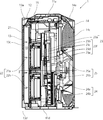
- FIG. 2 is a sectional view taken along line XX in FIG.
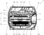
- FIG. 2 is a YY sectional view in FIG. 1.
- positioning explanatory drawing of a dust collection unit It is a principal part perspective view in embodiment of this invention, and is arrangement
- the housing of the air cleaner 1 includes a main body 11, a front panel 12, and a rear panel 14.
- the main body 11 includes a top panel 11a, a right panel 11b, a left panel 11c, and a bottom 11d each formed of a synthetic resin material, and is formed in a substantially rectangular parallelepiped shape.
- the front panel 12 is formed by molding a synthetic resin material, and is disposed on one surface of the main body 11.
- the rear panel 14 is formed by molding a synthetic resin material, and is disposed on the other surface of the main body 11. Further, the surface including the top panel 11a, the upper end of the front panel 12, and the upper end of the rear panel 14 is the upper surface of the housing.
- a surface including the right side panel 11b, the right end of the front panel 12, and the right end of the rear panel 14 is the right side of the casing.
- the surface including the left side panel 11c, the left end of the front panel 12, and the left end of the rear panel 14 is the left side of the housing.
- a surface including the bottom 11d, the lower end of the front panel 12, and the lower end of the rear panel 14 is a bottom surface of the housing.
- the side on which the front panel 12 is arranged is referred to as the front side with the main body 11 as a reference, and the side on which the rear panel 14 is arranged on the basis of the main body 11 as necessary. Is referred to as the back side.
- a front panel 13 made of a synthetic resin material is disposed in front of the front panel 12. Between the front panel 13 and the front panel 12, gaps are formed at four locations on the upper, lower, left, and right sides. These four gaps are formed on the front side of each of the top, bottom, left side, and right side of the housing.
- a gap formed on the front surface side of the upper surface of the housing is the upper surface suction port 13a.
- a gap formed on the front side of the right side of the housing is the right side suction port 13b.
- a gap formed on the front side of the left side of the housing is the left side suction port 13c.
- a gap formed on the front surface side of the bottom surface of the housing is a bottom surface suction port 13d.
- the upper surface suction port 13a, the right side surface suction port 13b, the left side surface suction port 13c, and the bottom surface suction port 13d are air suction ports that take air into the housing of the air cleaner 1 according to the present embodiment. That is, the air suction port of the air cleaner 1 includes an upper surface suction port 13a, a right side suction port 13b, a left side suction port 13c, and a bottom surface suction port 13d, which are disposed on the front side of the housing. In addition, the air cleaner 1 does not need to be provided with the bottom face inlet 13d.
- the air suction port of the air cleaner 1 may be configured to include an upper surface suction port 13a, a right side suction port 13b, and a left side suction port 13c that are disposed on the front side of the housing. Moreover, the air suction port of the air cleaner 1 may be at least one of the upper surface suction port 13a, the right side surface suction port 13b, and the left side surface suction port 13c. That is, the air inlet port of the air cleaner 1 may be disposed on at least one of the upper surface, the left side surface, and the right side surface on the front side of the housing.
- the upper surface suction port 13a, the right side surface suction port 13b, the left side surface suction port 13c, and the bottom surface suction port 13d which are the air suction ports of the air purifier 1, are formed between the front panel 13 and the front panel 12 ( Part of the gap).
- gaps are formed at three locations on the upper, left, and right sides between the main body 11 and the rear panel 14. These three gaps are formed on the back side of each of the top, left and right sides of the housing.
- a gap formed on the rear surface side of the upper surface of the housing is the upper air outlet 14a.
- a gap formed on the rear side of the right side surface of the housing is the right side air outlet 14b.
- a gap formed on the rear side of the left side of the housing is the left side outlet 14c.
- the upper surface outlet 14a, the right side outlet 14b, and the left side outlet 14c are air outlets that discharge air from the inside of the housing of the air purifier 1 according to the present embodiment to the outside.
- the air outlet of the air purifier 1 includes an upper surface outlet 14a, a right side outlet 14b, and a left side outlet 14c arranged on the back side of the casing. That is, the air blower outlet of the air cleaner 1 is arrange
- the upper air outlet 14a, the right side air outlet 14b, and the left side air outlet 14c, which are air outlets of the air purifier 1, are part of a gap (gap) between the main body 11 and the rear panel 14.
- air sucked (taken in) from the upper surface inlet 13 a, the right side inlet 13 b, the left side inlet 13 c, and the bottom inlet 13 d into the main body 11 is taken into the upper outlet 14 a, The air is blown into the room from the right side air outlet 14b and the left side air outlet 14c. During this time, dust removal, humidification and deodorization are performed on the air.
- the space inside the main body 11 that communicates with the air outlet 14c is the ventilation path 10 in the air cleaner 1 of the present embodiment.
- each suction port side in the ventilation path 10 is made into an upstream, as needed, each blower outlet side is demonstrated as a downstream.
- the operation unit 15 is provided on the upper surface of the housing of the air cleaner 1 so as to cover a part of the upper surface suction port 13a.
- the operation unit 15 is provided with buttons for operating the air cleaner 1 such as a power button and an operation mode switching button. Further, a display unit is disposed on the operation unit 15. The display unit displays the operation state of the air cleaner 1 and the detection result in a detector such as a dust sensor (not shown).
- a prefilter 21, a dust collection unit 22, a deodorizing unit 23, a humidification unit 24, and a blower are provided in the ventilation path 10 inside the main body 11 of the air cleaner 1 from the upstream side toward the downstream side. 25 are arranged in this order.
- the prefilter 21 is formed, for example, by braiding a thread-like PET material and has a mesh structure.
- the pre-filter 21 removes (or collects) dust contained in the air sucked into the main body 11.
- the pre-filter 21 has an arch shape that is convex toward the front side of the main body.
- the main body portion 11 includes the upper surface suction port 13a, the right side surface suction port 13b, the left side surface suction port 13c, and the bottom surface suction port 13d as compared with the case where the prefilter 21 has a flat shape.
- the area of the pre-filter 21 through which the air sucked into the air passes passes. For this reason, the pre-filter 21 can remove more dust.
- the dust collection unit 22 includes a first electric dust collector 22a and a second electric dust collector 22b.
- the first electrostatic precipitator 22a and the second electrostatic precipitator 22b are arranged so as to be lined up and down.
- the first electric dust collector 22a and the second electric dust collector 22b have a discharge electrode and a dust collection electrode (not shown).
- the first electrostatic precipitator 22a and the second electrostatic precipitator 22b charge fine dust and pollen that have not been removed by the prefilter 21 by corona discharge by the discharge electrode, and remove the charged dust and pollen by the dust collection electrode. To do.
- the first electrostatic precipitator 22a and the second electrostatic precipitator 22b are mainly composed of the above-described discharge electrode, dust collecting electrode, and a housing for holding them. For this reason, the air resistance of the dust collection unit 22 is small compared with the air resistance of the dust collection filter which consists of a nonwoven fabric formed in the pleat shape.
- drawing of the front panel 13 is omitted in order to clearly show the dust collection unit 22 (the first electric dust collector 22a and the second electric dust collector 22b).
- the deodorizing unit 23 includes a deodorizing filter 23 a and a heating unit (heating means) 23 f.
- the deodorizing filter 23a includes a disk-shaped base material 23aa having a porous structure such as a corrugated structure or a honeycomb structure.
- the corrugated structure includes, for example, flat plates that are alternately stacked and a bent material that is continuously bent into a corrugated shape.
- the base material 23aa is provided with a catalyst layer (deodorizing layer) 23ab that adsorbs and decomposes odor components.
- the catalyst layer (deodorizing layer) 23ab may be a deodorizing layer that decomposes and / or adsorbs odor components.
- the deodorizing filter 23a has a disk shape and is configured to be rotatable.
- the deodorizing filter 23a is rotatably supported by the main body 11 (or the housing).
- the heating unit 23f includes a PTC heater 23b, two heat radiating plates 23c, two heat insulating materials 23d, and two cases 23e.
- the PTC heater 23b is attached to the heat radiating plate 23c disposed on the front side of the main body portion of the two heat radiating plates 23c, and heats the two heat radiating plates 23c.
- Each of the two heat sinks 23c is a metal plate having a substantially triangular shape. As shown in FIGS. 4 and 6, the heat radiating plate 23c is arranged so as to cover only a part of the deodorizing filter 23a.
- the two heat sinks 23c are configured to contact each other in the vicinity of the central portion of the deodorizing filter 23a or on the outer diameter side of the deodorizing filter 23a. Therefore, the PTC heater 23b heats not only the heat radiating plate 23c disposed on the front side of the main body but also the heat radiating plate 23c on the rear side of the main body.
- the heat insulating material 23d is disposed so as to cover the PTC heater 23b and the heat radiating plate 23c.
- the heat insulating material 23d suppresses heat from escaping to the outside from the PTC heater 23b and the heat radiating plate 23c.
- the case 23e has a shape that can hold the PTC heater 23b, the heat radiating plate 23c, and the heat insulating material 23d.
- the deodorizing filter 23a has a porous structure
- the heating unit 23f has a structure that covers only a part of the deodorizing filter 23a. That is, the deodorizing filter 23 a is arranged so that a part thereof is exposed to the ventilation path 10. For this reason, the air resistance of the deodorizing filter 23a is small.
- the PTC heater 23b heats the two heat radiating plates 23c to heat a part of the deodorizing filter 23a covered with the two heat radiating plates 23c.
- the deodorizing filter 23a By heating the deodorizing filter 23a while rotating the deodorizing filter 23a by a motor (not shown), decomposition of the odor component adsorbed on the catalyst layer 23ab of the deodorizing filter 23a is promoted. Thereby, the deodorizing ability of the deodorizing filter 23a is reproduced.
- the deodorizing filter 23a may be heated by moving the heat radiating plate 23c.
- the deodorizing unit 23 does not need to have said structure.
- the deodorizing unit 23 does not need to have a heating means (PTC heater 23b and heat sink 23c).
- the deodorizing filter of the deodorizing unit 23 includes an adsorbent of odor components such as activated carbon instead of the catalyst layer, and a base material to which the adsorbent is added.
- the deodorizing capacity of the deodorizing unit 23 can be recovered by replacing the deodorizing filter with a new one.
- the humidification unit 24 has a humidification filter 24a and a water storage tank 24b for storing water.
- the humidification filter 24a is formed in a disk shape. A part of the humidifying filter 24a is rotatably supported by a rotating shaft in a state where a part of the humidifying filter 24a is immersed in water stored in the water storage tank 24b.
- the humidifying filter 24a sucks up moisture by being rotated by a motor (not shown).
- the humidification unit 24 does not need to have said structure.
- the humidifying unit 24 may include a humidifying filter that sucks up moisture by capillary action instead of the humidifying filter 24a.
- FIG. 6 in order to clearly show the deodorizing unit 23 and the humidifying unit 24, drawing of the members constituting the main body portion 11 other than the front panel 13 and the bottom portion 11 d, the dust collection unit 22, and the like is appropriately performed. Omitted.
- the blower 25 includes a turbo fan 25a and a fan motor 25b.
- the turbo fan 25a is made of a synthetic resin material and is connected to the output shaft of the fan motor 25b.
- the fan motor 25b is a variable speed motor.
- the fan motor 25b is disposed closer to the air inlet side (upstream side) than the turbo fan 25a.
- the turbo fan 25a also rotates.
- air flows into the air purifier 1 and air flows out from the air purifier 1.
- drawing of the members constituting the main body 11, the dust collection unit 22, the deodorizing unit 23, the humidifying unit 24, and the like other than the front panel 13 and the bottom 11 d is appropriately performed. Omitted.
- the air cleaner 1 is installed in a room 300 as shown in FIG.
- the room 300 includes a ceiling surface 300a, a floor surface 300b, and four side wall surfaces 300c.
- the rear panel 14 of the air cleaner 1 is disposed in close proximity to one surface of the side wall surface 300c so as to face this surface.
- the air sucked into the main body 11 flows as follows. (1) In the place where the lower part of the deodorizing unit 23 and the upper part of the humidifying unit 24 are arranged in the front-rear direction in the ventilation path 10, the prefilter 21 ⁇ the dust collecting unit 22 ⁇ the deodorizing unit 23 ⁇ the humidifying unit 24 In order, air flows. (2) In a place where the lower part of the deodorizing unit 23 and the upper part of the humidifying unit 24 are not overlapped in the front-rear direction in the ventilation path 10, in order of the prefilter 21 ⁇ the dust collecting unit 22 ⁇ the deodorizing unit 23, or The air flows in the order of the pre-filter 21 ⁇ the dust collecting unit 22 ⁇ the humidifying unit 24.
- the prefilter 21 and the energized dust collecting unit 22 remove dust and pollen contained in the sucked air.
- the deodorizing unit 23 removes the odor component contained in the sucked air.
- the humidifying unit 24 humidifies the sucked air.
- FIG. 8 (A) the air that has been subjected to dust removal, deodorization, and humidification is shown in FIG. 8 (A) as indicated by the solid line arrow 200, in the upper surface outlet 14a, the right side outlet 14b, and the left side outlet 14c.
- the air purifier 1 is blown out from the three-way outlet.
- the air blown out from each air outlet is arranged in the air cleaner 1 along the ceiling surface 300a or the side wall surface 300c of the room 300 as shown by the solid arrow 200 in FIG. 8B. It flows toward the back side of the room 300 when viewed from the side of the side wall surface 300c opposite to the side wall surface 300c, that is, from the air cleaner 1.
- the air blown from the upper surface outlet 14a flows toward the back side of the room 300 along the ceiling surface 300a.
- the air blown out from the right side air outlet 14b flows toward the back side of the room 300 along the right side wall surface 300c.
- the air blown out from the left side air outlet 14c flows toward the back side of the room 300 along the left side wall surface 300c.
- the purified and humidified air is blown out so as to enclose the room 300 in which the air purifier 1 is installed. Further, the rear panel 14 is disposed in close proximity to this surface so as to face the side wall surface 300c.
- the air cleaner 1 includes an upper surface inlet 13a, a right side inlet 13b, a left side inlet 13c, and The air in the room 300 is sucked from the four-way suction ports of the bottom surface suction port 13d. For this reason, the air cleaner 1 can improve the air flow in the room 300. As a result, the air purifier 1 can suck in the air in the room 300 evenly, and remove dust, humidify and deodorize it.
- the air cleaner 1 can suck dust, pollen, odor components, and the like adhering to and scattering from the floor surface 300b together with the air sucked from the bottom surface suction port 13d.
- the air cleaner 1 can improve the air circulation in the room 300 including the floor surface 300b. As a result, the air cleaner 1 can purify the air in the entire room 300 more effectively.
- a conventional air cleaner (dust remover) is described in, for example, Japanese Patent Application Laid-Open No. 2000-167326.
- air is sucked into the housing from the through hole of the front wall through the front filter unit.
- a mesh is also provided on the front surface of the front filter unit. Therefore, it is difficult to improve the design of the dust removing device.
- an upper surface suction port 13a, a right side surface suction port 13b, a left side surface suction port 13c, and a bottom surface suction port 13d are disposed around a space formed on the front surface side of the housing. Is provided.
- the air inlet is not provided in the front panel 13 on the front surface of the housing, the design of the air cleaner 1 is improved. That is, in this embodiment, it is possible to improve the air circulation in the room, and it is possible to provide the air cleaner 1 having a relatively high design property.
- the air resistance of the dust collection unit 22 is small compared with the air resistance of the dust collection filter which consists of a nonwoven fabric formed in the pleat shape.
- the heating unit 23f has a structure that covers only a part of the deodorizing filter 23a. That is, the deodorizing filter 23 a is arranged so that a part thereof is exposed to the ventilation path 10. Therefore, the air resistance of the deodorizing unit 23 is also smaller than the air resistance of the deodorizing unit having a plate-shaped heating portion formed so as to have substantially the same area as that of the conventional catalyst filter.
- the turbo fan 25a which has a static pressure lower than a sirocco fan can be used for the air blower 25.
- the turbo fan 25a When the turbo fan 25a is used and the air resistance is the same, the air volume is smaller than when the sirocco fan is used. However, the turbo fan 25a has higher efficiency and higher noise performance than the sirocco fan. For this reason, the air cleaner 1 which can suppress noise, ensuring the required dust collection capability and deodorizing capability is realizable.
- the turbo fan 25a does not have to include the scroll housing provided in the sirocco fan, and thus can be reduced in size and thickness as compared with the sirocco fan. For this reason, it can suppress that the housing dimension of the air cleaner 1 becomes large too much, ensuring the distance L mentioned later.
- the air resistance of the dust collection unit 22 and the deodorizing unit 23 is small. Therefore, as shown in FIGS. 3 to 7, when the dust collection unit 22, the deodorizing unit 23, the humidifying unit 24, and the blower 25 are arranged in this order from the upstream side to the downstream side of the ventilation path 10. However, the air resistance in the air cleaner 1 does not increase so much. Therefore, the amount of air flowing through the ventilation path 10 inside the main body 11 is not reduced by driving the blower 25. And the dimension of the front-back (depth) direction in the main-body part 11 becomes long by arrange
- the distance L between each air inlet port and each air outlet port shown in FIG. 4 can be increased.
- the air blown into the room from each air outlet is immediately sucked into the air purifier 1 from each air inlet, thus generating a short circuit between the so-called air inlet and the air outlet. Is suppressed.
- the dust collection unit 22 is disposed upstream of the deodorizing unit 23.
- the air flowing into the deodorizing unit 23 is air from which dust, pollen and the like have been removed. Therefore, clogging of the deodorizing filter 23a of the deodorizing unit 23 due to dust or pollen is suppressed.
- a fan motor 25b and a turbo fan 25a are arranged in this order from each air inlet to each air outlet. That is, the turbo fan 25a is arranged at a position farthest from each air suction port, and each air outlet is arranged corresponding to the arrangement of the turbo fan 25a. For this reason, the distance L between each air inlet and each air outlet can be further increased. As a result, a higher effect of suppressing the occurrence of a short circuit can be obtained.
- the arrangement order of the turbo fan 25a and the fan motor 25b may be reverse to the above.
- a conventional air cleaner is disclosed in, for example, Japanese Patent Application Laid-Open No. 2009-22882.
- air suction ports are provided in upper and lower spaces formed between the partition plate and the front panel.
- air outlets are provided on the left and right side surfaces of the main body casing. Therefore, in order to suppress a short circuit, an air blower outlet can be provided only in two places on the left and right side surfaces of the housing. For this reason, there is a possibility that the amount of air released from the housing of the air purifier cannot be sufficiently secured and the sufficient air purification ability cannot be exhibited. Further, in the air purifier described in Japanese Patent Application Laid-Open No.
- both end portions (upper and lower end portions) of the air outlets provided on the left and right side surfaces of the casing are provided on the upper and lower side surfaces of the casing. Located near the air inlet. For this reason, the air discharged
- the upper surface inlet 13a, the right side inlet 13b for sucking air into the inside of the air cleaner 1 through the four gaps formed on the front side of the housing, upper, lower, left and right, The left side inlet 13c and the bottom inlet 13d can be used. Furthermore, an upper surface outlet 14a, a right side outlet 14b, and a left side outlet for blowing out air from the inside of the air purifier 1 in the three spaces, upper, left and right, formed on the back side of the housing. 14c.
- the air suction amount and the blowing amount can be sufficiently ensured. That is, in the present embodiment, as described above, it is possible to provide the air purifier 1 that can secure a sufficient dust collecting ability and deodorizing ability and can more reliably suppress a short circuit.
- the center height of the fan motor 25b is adjusted to the height of the space between the first electric dust collector 22a and the second electric dust collector 22b of the dust collection unit 22.
- the space between the first electric dust collector 22a and the second electric dust collector 22b has a small dust collecting ability with respect to the passing air.
- the first electrostatic precipitator 22a and the first electric dust collector 22a are placed in a space where the blades of the turbo fan 25a are present, which is considered to have a large air flow.
- 2 electric dust collectors 22b can be arranged. Thereby, dust removal by the dust collection unit 22 can be performed efficiently.
- the air cleaner 1 has a substantially rectangular parallelepiped housing
- the shape of the housing of the air purifier 1 is not limited to this, and is a polyhedral shape having an upper surface, a bottom surface, a left side surface, and a right side surface, and an air inlet or an air outlet provided on each surface. I just need it.
- the air cleaner 1 is provided with both the deodorizing unit 23 and the humidification unit 24.
- the present invention is not limited to this, and the air cleaner 1 may be configured to include either the deodorizing unit 23 or the humidifying unit 24.
- the air cleaner according to the embodiment of the present invention may be the following first to eleventh air cleaners.
- the first air cleaner includes a main body including an air suction port for sucking air into the housing, an air outlet for blowing air from the inside of the housing to the outside, and a ventilation path for communicating the air suction port and the air outlet.
- An air cleaner comprising: a dust collecting unit that removes the taken-in air in the main body, a deodorizing unit that deodorizes the taken-in air, and a blower.
- the deodorizing unit includes a deodorizing filter in which a deodorizing layer that decomposes and / or adsorbs an odor component is provided on a base material having a porous structure, and the deodorizing filter is exposed in the main body.
- the blower includes a turbo fan and a fan motor that rotates the turbo fan.
- a 2nd air cleaner is a 1st air cleaner, Comprising: The said dust collection unit, the said deodorizing unit, and the said air blower in the said main body part in the direction which goes to the said air blower outlet from the said air suction inlet. Has been placed.
- a 3rd air cleaner is a 1st or 2nd air cleaner.
- the said deodorizing layer is a catalyst layer by which decomposition
- the fourth air cleaner is any one of the first to third air cleaners, wherein the deodorizing filter is formed in a disc shape and is rotatably supported in the main body.
- the fifth air cleaner is the air cleaner according to any one of the first to fourth air cleaners, wherein the air suction port includes an upper surface suction port, a right side surface suction port, and a left side surface suction disposed on the front side of the main body.
- the air outlet is composed of an upper surface outlet, a right side outlet, and a left side outlet that are disposed on the back side of the main body.
- the sixth air cleaner includes an air suction port that takes air into the housing, an air outlet that discharges air from the inside of the housing to the outside, and an air passage that communicates the air suction port and the air outlet.
- a main body and a dust collecting unit that removes the captured air, a deodorizing unit that deodorizes the captured air, and / or a humidifying unit that humidifies the captured air, and an air blower.
- a cleaner comprising a front panel disposed on the front side of the main body, a front panel disposed on the front side of the front panel, and a rear panel disposed on the back side of the main body, Of the gap formed between the front panel and the front panel, at least one of the upper end portion and the left and right side end portions serves as the air suction port, and is between the rear surface of the main body portion and the rear panel. Of the gap formed, the upper and left and right side end portion is placed in the said air outlet.
- a 7th air cleaner is a 6th air cleaner, Comprising: The said dust collection unit, the said deodorizing unit, and the said air blower in the said main body part in the direction which goes to the said air blower outlet from the said air suction inlet.
- the eighth air cleaner is the sixth or seventh air cleaner, wherein the blower has a turbo fan and a fan motor that rotates the turbo fan, and the fan motor is more Arranged on the air inlet side.
- the ninth air cleaner has an air suction port for taking air into the housing and an air outlet for releasing air from the inside of the housing to the outside, and the air suction port and the air outlet are disposed in the housing.
- an air cleaner having a dust collecting unit and a blower for removing dust taken in the ventilation path
- the housing includes at least a front surface, a back surface, an upper surface, A bottom surface, a left side surface, and a right side surface
- the air suction port is disposed on the top surface, the bottom surface, the left side surface, and the right side surface on the front side of the housing, and the air outlet is Arranged on the upper surface, the left side surface and the right side surface on the back side of the housing.
- a tenth air purifier is the ninth air purifier, comprising at least one of a deodorizing unit for deodorizing the taken-in air or a humidifying unit for humidifying the taken-in air in the ventilation path, the deodorizing unit And / or the humidification unit is arranged downstream of the dust collection unit.
- the eleventh air cleaner is used by being arranged so that the back side of the casing faces the side wall surface of the room.
- SYMBOLS 1 Air cleaner 10 Ventilation path 11 Main part 12 Front panel 13 Front panel 13a Top surface inlet 13b Right side inlet 13c Left side inlet 13d Bottom inlet 14 Rear panel 14a Upper side outlet 14b Right side outlet 14c Left side outlet DESCRIPTION OF SYMBOLS 15 Operation part 21 Pre filter 22 Dust collection unit 22a 1st electrostatic dust collector 22b 2nd electrical dust collector 23 Deodorizing unit 23aa Base material 23ab Catalyst layer 23a Deodorizing filter 23b PTC heater 23c Heat sink 23f Heating part 24 Humidification unit 24a Humidification filter 24b Water storage tank 25 Blower 25a Turbo fan 25b Fan motor 300 Room 300c Side wall surface
Landscapes
- Engineering & Computer Science (AREA)
- Chemical & Material Sciences (AREA)
- Combustion & Propulsion (AREA)
- Mechanical Engineering (AREA)
- General Engineering & Computer Science (AREA)
- Health & Medical Sciences (AREA)
- Epidemiology (AREA)
- Life Sciences & Earth Sciences (AREA)
- Animal Behavior & Ethology (AREA)
- General Health & Medical Sciences (AREA)
- Public Health (AREA)
- Veterinary Medicine (AREA)
- Disinfection, Sterilisation Or Deodorisation Of Air (AREA)
Abstract
【課題】本発明の実施形態にかかる1つの課題は、十分な集塵能力および脱臭能力を有するとともに、騒音を抑制することの可能な空気清浄機を提供することにある。 【解決手段】空気清浄機1は、集塵ユニット22、脱臭ユニット23および送風機25を有する。集塵ユニット22は、小さい空気抵抗を有する、2台の電気集塵機を含む。脱臭ユニット23では、2枚の放熱板23cが、脱臭フィルタ23aの一部のみを覆っている。このため、脱臭ユニット23は、小さい空気抵抗を有する。したがって、送風機25が比較的に静かなターボファン25aを有していても、空気流量を十分に確保できるので、十分な集塵能力および脱臭能力を得ることができる。
Description
本発明は、筐体内部に取り込んだ空気を浄化して部屋に放出する空気清浄機に関する。
従来、空気清浄機は、たとえば、本体筐体内に設けられた送風機の駆動によって、本体筐体内に吸い込んだ空気を、集塵フィルタと加湿ユニットと脱臭ユニットとに順次通過させる(例えば、特開2014-52084号公報参照)。
特開2014-52084号公報に記載の空気清浄機は、空気吸込口から本体筐体内に吸い込んだ空気を空気吹出口へ導く送風路を有している。送風路には、空気吸込口から空気吹出口へ向かう方向に沿って、順に、プレフィルタ、集塵フィルタ、脱臭ユニット、加湿ユニットおよび送風機が配置されている。
プレフィルタは、例えば、糸状のPET材を編み込むことによって形成され、網目構造を有する。集塵フィルタは、例えば、プリーツ形状に形成された不織布からなる。加湿ユニットは、プリーツ形状を有する加湿フィルタと、加湿フィルタに水を供給する貯水タンクとを備える。脱臭ユニットは、臭気成分を吸着して分解する触媒フィルタと、この触媒フィルタの全体を覆う加熱部とを備える。脱臭ユニットでは、加熱部が触媒フィルタを加熱することによって、触媒フィルタの脱臭能力が再生される。送風機は、回転数可変のファンモータと、ファンモータの出力軸に接続されたシロッコファンとを備えている。
送風機の駆動により、空気吸込口から送風路に吸い込まれた空気は、プレフィルタおよび集塵フィルタを通過する。この際に、空気に含まれる塵埃が除去される。さらに、集塵フィルタを通過した空気は、加湿ユニットを通過する際に加湿される。そして、加湿ユニットを通過した空気は、脱臭ユニットを通過する。この際に、空気に含まれる臭気成分が除去される。このようにして浄化された空気は、送風機の駆動により、空気吹出口から室内に吹き出される。
特開2014-52084号公報に記載の空気清浄機では、高い静圧を有するシロッコファンが採用されている。したがって、空気抵抗の大きい、集塵フィルタおよび脱臭ユニットを用いても、空気の浄化に必要な風量を確保できる。しかし、上述したように、シロッコファンの静圧は高い。このため、空気清浄機の静粛性を高めることには限界がある。一方、低い静圧を有するファンでは、集塵フィルタおよび脱臭ユニットの空気抵抗によって、空気の浄化に必要な風量を確保することが困難であり、十分な集塵能力および脱臭能力が得られない可能性がある。
本発明の実施形態における1つの目的は、以上述べた問題点を解決し、十分な集塵能力および脱臭能力を得られるとともに、騒音を抑制することの可能な、空気清浄機を提供することにある。
本発明は上述の課題を解決するものであって、本発明の第1の態様にかかる空気清浄機は、筐体内に空気を取り込む空気吸込口と、筐体内から外部へ空気を放出する空気吹出口と、前記空気吸込口と前記空気吹出口とを連通させる通風路と、前記通風路に備えられ、取り込んだ空気を除塵する集塵ユニットと、前記通風路に備えられ、取り込んだ空気を脱臭する脱臭ユニットと、前記通風路に備えられた送風機と、を備え、前記集塵ユニットは電気集塵機を含んでおり、前記脱臭ユニットは、多孔構造を有する基材、および、この基材に設けられ、臭気成分を分解および/または吸着する脱臭層を含む脱臭フィルタを有し、前記脱臭フィルタが、その一部が、前記通風路に露出されるように配置され、前記送風機は、ターボファンと、同ターボファンを回転させるファンモータとを有する。
第1の態様にかかる空気清浄機は、空気抵抗の小さい電気集塵機を含む集塵ユニットと、多孔構造を有するために、小さい空気抵抗を有する、脱臭ユニットと、ターボファンを有する送風機と、を備えている。集塵ユニットおよび脱臭ユニットの空気抵抗が小さいため、シロッコファンより低い静圧を有するターボファンを用いることができる。つまり、空気抵抗が同じである場合に、ターボファンの風量は、シロッコファンの風量よりも小さい。しかし、集塵ユニットおよび脱臭ユニットの空気抵抗が小さいため、ターボファンを用いても、空気清浄機内部での空気流量を十分確保できる。このため、この空気清浄機は、十分な集塵能力および脱臭能力を得ることができる。また、ターボファンを用いることによって、シロッコファンを用いる場合と比べて騒音を抑制できる。このため、この空気清浄機では、その静粛性を改善できる。
本発明の第2の態様にかかる空気清浄機は、筐体内に空気を取り込む空気吸込口と、筐体内から外部へ空気を放出する空気吹出口と、前記空気吸込口と前記空気吹出口とを連通させる通風路と、前記通風路に備えられ、取り込んだ空気を除塵する集塵ユニットと、前記通風路に備えられた送風機と、を備え、前記筐体は、前面、背面、上面、底面、左側面および右側面を有し、前記空気吸込口は、前記筐体の前面側における、前記上面、前記左側面および前記右側面の少なくとも1つに配置され、前記空気吹出口は、前記筐体の背面側における、前記上面、前記左側面および前記右側面に配置される。
この空気清浄機は、3つの空気吹出口を有している。このため、筐体からの空気の放出量を、十分に確保できる。また、空気吸込口と空気吹出口とは、本体部の前面側と背面側とに離れて配置されている。このため、より確実にショートサーキットを抑制することができる。
本発明の第2の態様にかかる空気清浄機は、筐体内に空気を取り込む空気吸込口と、筐体内から外部へ空気を放出する空気吹出口と、前記空気吸込口と前記空気吹出口とを連通させる通風路と、前記通風路に備えられ、取り込んだ空気を除塵する集塵ユニットと、前記通風路に備えられた送風機と、を備え、前記筐体は、前面、背面、上面、底面、左側面および右側面を有し、前記空気吸込口は、前記筐体の前面側における、前記上面、前記左側面および前記右側面の少なくとも1つに配置され、前記空気吹出口は、前記筐体の背面側における、前記上面、前記左側面および前記右側面に配置される。
この空気清浄機は、3つの空気吹出口を有している。このため、筐体からの空気の放出量を、十分に確保できる。また、空気吸込口と空気吹出口とは、本体部の前面側と背面側とに離れて配置されている。このため、より確実にショートサーキットを抑制することができる。
以下、本発明の実施の形態を、添付図面に基づいて詳細に説明する。尚、本発明は以下の実施形態に限定されることはなく、本発明の主旨を逸脱しない範囲で種々変形することが可能である。
図1および図2に示すように、本発明の一実施形態である空気清浄機1の筐体は、本体部11と、前面パネル12と、リアパネル14と、を含んでいる。本体部11は、各々合成樹脂材で成形された天面パネル11a、右側面パネル11b、左側面パネル11cおよび底部11dを備えており、略直方体状に形成されている。前面パネル12は、合成樹脂材を成形することによって形成されており、本体部11の一方の面に配置されている。リアパネル14は、合成樹脂材を成形することによって形成されており、本体部11の他方の面に配置されている。
また、天面パネル11a、前面パネル12の上端部およびリアパネル14の上端部を含む面が、筐体の上面である。右側面パネル11b、前面パネル12の右側端部およびリアパネル14の右側端部を含む面が、筐体の右側面である。左側面パネル11c、前面パネル12の左側端部およびリアパネル14の左側端部を含む面が、筐体の左側面である。底部11d、前面パネル12の下端部およびリアパネル14の下端部を含む面が、筐体の底面である。
尚、以降の説明では、必要に応じて、本体部11を基準として、前面パネル12が配置されている側を前面側と称するとともに、本体部11を基準として、リアパネル14が配置されている側を背面側と称する。
また、天面パネル11a、前面パネル12の上端部およびリアパネル14の上端部を含む面が、筐体の上面である。右側面パネル11b、前面パネル12の右側端部およびリアパネル14の右側端部を含む面が、筐体の右側面である。左側面パネル11c、前面パネル12の左側端部およびリアパネル14の左側端部を含む面が、筐体の左側面である。底部11d、前面パネル12の下端部およびリアパネル14の下端部を含む面が、筐体の底面である。
尚、以降の説明では、必要に応じて、本体部11を基準として、前面パネル12が配置されている側を前面側と称するとともに、本体部11を基準として、リアパネル14が配置されている側を背面側と称する。
前面パネル12の前方には、合成樹脂材から形成されたフロントパネル13が配置される。フロントパネル13と前面パネル12との間における、上、下、左および右側の4カ所に、隙間が形成される。これら4カ所の隙間は、筐体の上面、底面、左側面および右側面のそれぞれの、前面側に形成される。筐体上面の前面側に形成される隙間が、上面吸込口13aである。筐体右側面の前面側に形成される隙間が、右側面吸込口13bである。筐体左側面の前面側に形成される隙間が、左側面吸込口13cである。筐体底面の前面側に形成される隙間が、底面吸込口13dである。これら上面吸込口13a、右側面吸込口13b、左側面吸込口13cおよび底面吸込口13dが、本実施形態にかかる空気清浄機1の筐体内に空気を取り込む空気吸込口である。すなわち、空気清浄機1の空気吸込口は、筐体の前面側に配置される、上面吸込口13a、右側面吸込口13b、左側面吸込口13c、および、底面吸込口13dを含んでいる。
なお、空気清浄機1は、底面吸込口13dを備えていなくてもよい。すなわち、空気清浄機1の空気吸込口は、筐体の前面側に配置される、上面吸込口13a、右側面吸込口13b、および、左側面吸込口13cを含むように構成されていてもよい。また、空気清浄機1の空気吸込口は、上面吸込口13a、右側面吸込口13b、および、左側面吸込口13cの少なくとも1つであってもよい。すなわち、空気清浄機1の空気吸込口は、筐体の前面側における、上面、左側面および右側面の少なくとも1つに配置されていてもよい。
なお、空気清浄機1の空気吸込口である上面吸込口13a、右側面吸込口13b、左側面吸込口13c、および、底面吸込口13dは、フロントパネル13と前面パネル12との間の隙間(間隙)の一部である。
なお、空気清浄機1は、底面吸込口13dを備えていなくてもよい。すなわち、空気清浄機1の空気吸込口は、筐体の前面側に配置される、上面吸込口13a、右側面吸込口13b、および、左側面吸込口13cを含むように構成されていてもよい。また、空気清浄機1の空気吸込口は、上面吸込口13a、右側面吸込口13b、および、左側面吸込口13cの少なくとも1つであってもよい。すなわち、空気清浄機1の空気吸込口は、筐体の前面側における、上面、左側面および右側面の少なくとも1つに配置されていてもよい。
なお、空気清浄機1の空気吸込口である上面吸込口13a、右側面吸込口13b、左側面吸込口13c、および、底面吸込口13dは、フロントパネル13と前面パネル12との間の隙間(間隙)の一部である。
また、本体部11とリアパネル14との間における、上、左および右側の3か所に、隙間が形成される。これら3カ所の隙間は、筐体の上面、左側面および右側面のそれぞれの、背面側に形成される。筐体上面の背面側に形成される隙間が、上面吹出口14aである。筐体右側面の背面側に形成される隙間が、右側面吹出口14bである。筐体左側面の背面側に形成される隙間が、左側面吹出口14cである。これら上面吹出口14a、右側面吹出口14bおよび左側面吹出口14cが、本実施形態にかかる空気清浄機1の筐体内から外部へ空気を放出する空気吹出口である。すなわち、空気清浄機1の空気吹出口は、前記筐体の背面側に配置される、上面吹出口14a、右側面吹出口14bおよび左側面吹出口14cを含んでいる。すなわち、空気清浄機1の空気吹出口は、筐体の背面側における、上面、左側面および右側面に配置されている。
なお、空気清浄機1の空気吹出口である上面吹出口14a、右側面吹出口14bおよび左側面吹出口14cは、本体部11とリアパネル14との間の隙間(間隙)の一部である。
なお、空気清浄機1の空気吹出口である上面吹出口14a、右側面吹出口14bおよび左側面吹出口14cは、本体部11とリアパネル14との間の隙間(間隙)の一部である。
空気清浄機1では、上面吸込口13a、右側面吸込口13b、左側面吸込口13c、および底面吸込口13dから、本体部11に吸い込まれた(取り込まれた)空気が、上面吹出口14a、右側面吹出口14b、および左側面吹出口14cから、室内に吹き出される。この間に、空気に対する除塵、加湿および脱臭が行われる。
尚、図3および図4に示すように、上面吸込口13a、右側面吸込口13b、左側面吸込口13c、および底面吸込口13dと、上面吹出口14a、右側面吹出口14b、および左側面吹出口14cとを連通する、本体部11内部の空間が、本実施形態の空気清浄機1における通風路10となる。また、以下の説明では、必要に応じて、通風路10における各吸込口側を上流側とするとともに、各吹出口側を下流側として説明する。
空気清浄機1の筐体上面には、上面吸込口13aの一部を覆うように、操作部15が設けられている。操作部15には、電源ボタンおよび運転モード切り換えボタン等の、空気清浄機1を操作するボタンが配置される。さらに、操作部15には、表示部が配置されている。表示部は、空気清浄機1の運転状態、および、図示しない、塵埃センサ等の検出器における検出結果を表示する。
図3に示すように、空気清浄機1の本体部11内部の通風路10には、上流側から下流側に向かって、プレフィルタ21、集塵ユニット22、脱臭ユニット23、加湿ユニット24および送風機25が、この順に配置されている。
プレフィルタ21は、例えば、糸状のPET材を編みこむことによって形成され、網目構造を有する。プレフィルタ21は、本体部11内部に吸い込まれる空気に含まれる塵埃を除去(あるいは捕集)する。図4に示すように、プレフィルタ21は、本体部前面側に向かって凸となるようなアーチ形状を有している。プレフィルタ21がアーチ形状を有する場合、プレフィルタ21が平坦な形状を有する場合と比べて、上面吸込口13a、右側面吸込口13b、左側面吸込口13c、および底面吸込口13dから本体部11の内部に吸い込まれた空気が通過する、プレフィルタ21の面積が大きくなる。このため、プレフィルタ21は、より多くの塵埃を除去することができる。
図3および図5に示すように、集塵ユニット22は、第1電気集塵機22aと第2電気集塵機22bとを含んでいる。第1電気集塵機22aと第2電気集塵機22bとは、上下方向に並ぶように配置されている。第1電気集塵機22aおよび第2電気集塵機22bは、図示しない放電電極と集塵電極とを有している。第1電気集塵機22aおよび第2電気集塵機22bは、放電電極によるコロナ放電によりプレフィルタ21によって除去されなかった、細かな塵埃および花粉等を帯電させ、帯電した塵埃および花粉等を集塵電極によって除去する。第1電気集塵機22aおよび第2電気集塵機22bは、主に、上述した放電電極、集塵電極、および、これらを保持する筐体から構成されている。このため、集塵ユニット22の空気抵抗は、プリーツ形状に形成された不織布からなる集塵フィルタの空気抵抗に比べて、小さい。
尚、図5では、集塵ユニット22(第1電気集塵機22aおよび第2電気集塵機22b)を明示するために、フロントパネル13の描画を省略している。
尚、図5では、集塵ユニット22(第1電気集塵機22aおよび第2電気集塵機22b)を明示するために、フロントパネル13の描画を省略している。
図3、図4および図6に示すように、脱臭ユニット23は、脱臭フィルタ23aと加熱部(加熱手段)23fとを有する。図6に示すように、脱臭フィルタ23aは、例えば、波形構造あるいはハニカム構造のような多孔構造を有する、円板形状の基材23aaを含んでいる。波形構造は、たとえば、交互に積層された平板材、および、波形に連続屈曲した屈曲材を有する。基材23aaには、臭気成分を吸着して分解する触媒層(脱臭層)23abが設けられている。
なお、触媒層(脱臭層)23abは、臭気成分を分解および/または吸着する脱臭層であってもよい。また、脱臭フィルタ23aは、円板形状を有しており、回転可能に構成されている。たとえば、脱臭フィルタ23aは、本体部11(あるいは筐体)に、回転可能に支持されている。
図3および図4に示すように、加熱部23fは、PTCヒータ23bと、2枚の放熱板23cと、2個の断熱材23dと、2個のケース23eとを備えている。PTCヒータ23bは、2枚の放熱板23cのうち、本体部前面側に配置された放熱板23cに取り付けられており、2枚の放熱板23cを加熱する。2枚の放熱板23cは、各々、略三角形状を有する金属板である。図4および図6に示すように、放熱板23cは、脱臭フィルタ23aの一部のみを覆うように配置される。2枚の放熱板23cは、脱臭フィルタ23aの中央部の近傍あるいは、脱臭フィルタ23aの外径側で、互いに接触するように構成されている。このため、PTCヒータ23bにより、本体前面側に配置された放熱板23cだけではなく、本体背面側の放熱板23cも加熱される。断熱材23dは、PTCヒータ23bおよび放熱板23cを覆うように配置されている。断熱材23dは、PTCヒータ23bおよび放熱板23cから、外部に熱が逃げることを抑制する。ケース23eは、PTCヒータ23b、放熱板23cおよび断熱材23dを保持できる形状を有している。
このように、脱臭フィルタ23aが多孔構造を有しており、さらに、加熱部23fが、脱臭フィルタ23aの一部のみを覆う構造を有している。すなわち、脱臭フィルタ23aが、その一部が、通風路10に露出されるように配置されている。このため、脱臭フィルタ23aの空気抵抗は小さい。
なお、触媒層(脱臭層)23abは、臭気成分を分解および/または吸着する脱臭層であってもよい。また、脱臭フィルタ23aは、円板形状を有しており、回転可能に構成されている。たとえば、脱臭フィルタ23aは、本体部11(あるいは筐体)に、回転可能に支持されている。
図3および図4に示すように、加熱部23fは、PTCヒータ23bと、2枚の放熱板23cと、2個の断熱材23dと、2個のケース23eとを備えている。PTCヒータ23bは、2枚の放熱板23cのうち、本体部前面側に配置された放熱板23cに取り付けられており、2枚の放熱板23cを加熱する。2枚の放熱板23cは、各々、略三角形状を有する金属板である。図4および図6に示すように、放熱板23cは、脱臭フィルタ23aの一部のみを覆うように配置される。2枚の放熱板23cは、脱臭フィルタ23aの中央部の近傍あるいは、脱臭フィルタ23aの外径側で、互いに接触するように構成されている。このため、PTCヒータ23bにより、本体前面側に配置された放熱板23cだけではなく、本体背面側の放熱板23cも加熱される。断熱材23dは、PTCヒータ23bおよび放熱板23cを覆うように配置されている。断熱材23dは、PTCヒータ23bおよび放熱板23cから、外部に熱が逃げることを抑制する。ケース23eは、PTCヒータ23b、放熱板23cおよび断熱材23dを保持できる形状を有している。
このように、脱臭フィルタ23aが多孔構造を有しており、さらに、加熱部23fが、脱臭フィルタ23aの一部のみを覆う構造を有している。すなわち、脱臭フィルタ23aが、その一部が、通風路10に露出されるように配置されている。このため、脱臭フィルタ23aの空気抵抗は小さい。
脱臭フィルタ23aの脱臭能力を再生するときには、PTCヒータ23bにより、2枚の放熱板23cを加熱することによって、2枚の放熱板23cによって覆われた、脱臭フィルタ23aの一部を加熱する。図示しないモータによって脱臭フィルタ23aを回転させながら、脱臭フィルタ23aを加熱することによって、脱臭フィルタ23aの触媒層23abに吸着されていた臭気成分の分解が促進される。これにより、脱臭フィルタ23aの脱臭能力が再生される。尚、脱臭フィルタ23aを回転することに代えて、放熱板23cを移動することによって、脱臭フィルタ23aを加熱してもよい。
なお、脱臭ユニット23は、上記の構成を有していなくてもよい。脱臭ユニット23は、加熱手段(PTCヒータ23bおよび放熱板23c)を有していなくてもよい。この場合、脱臭ユニット23の脱臭フィルタは、触媒層の代わりの活性炭のような、臭気成分の吸着材、および、この吸着剤が添加された基材を含む。この場合、脱臭ユニット23の吸着能力が低下したときには、脱臭フィルタを新しいものに交換することにより、脱臭ユニット23の脱臭能力を回復できる。
なお、脱臭ユニット23は、上記の構成を有していなくてもよい。脱臭ユニット23は、加熱手段(PTCヒータ23bおよび放熱板23c)を有していなくてもよい。この場合、脱臭ユニット23の脱臭フィルタは、触媒層の代わりの活性炭のような、臭気成分の吸着材、および、この吸着剤が添加された基材を含む。この場合、脱臭ユニット23の吸着能力が低下したときには、脱臭フィルタを新しいものに交換することにより、脱臭ユニット23の脱臭能力を回復できる。
図3、図4および図6に示すように、加湿ユニット24は、加湿フィルタ24aと水を貯留する貯水タンク24bとを有する。加湿フィルタ24aは、円板形状に形成されている。加湿フィルタ24aは、その一部が、貯水タンク24bに溜められた水に浸った状態で、回転軸により回転可能に支持されている。加湿フィルタ24aは、図示しないモータにより回転することにより、水分を吸い上げる。
尚、加湿ユニット24は、上記の構成を有していなくてもよい。加湿ユニット24は、加湿フィルタ24aに代えて、毛細管現象によって水分を吸い上げる加湿フィルタを備えていてもよい。また、図6においては、脱臭ユニット23および加湿ユニット24を明示するために、フロントパネル13、底部11d以外の、本体部11を構成する部材、および、集塵ユニット22等の描画を、適宜、省略している。
尚、加湿ユニット24は、上記の構成を有していなくてもよい。加湿ユニット24は、加湿フィルタ24aに代えて、毛細管現象によって水分を吸い上げる加湿フィルタを備えていてもよい。また、図6においては、脱臭ユニット23および加湿ユニット24を明示するために、フロントパネル13、底部11d以外の、本体部11を構成する部材、および、集塵ユニット22等の描画を、適宜、省略している。
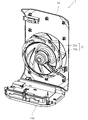
図3、図4および図7に示すように、送風機25は、ターボファン25aとファンモータ25bとを有する。ターボファン25aは、合成樹脂材から形成されており、ファンモータ25bの出力軸に接続されている。ファンモータ25bは、回転数可変型のモータである。ファンモータ25bは、ターボファン25aよりも、空気吸込口側(上流側)に配置されている。ファンモータ25bが回転することで、ターボファン25aも回転する。ターボファン25aの回転によって、空気清浄機1内部へ空気が流入するとともに、空気清浄機1内部から空気が流出する。尚、図7では、送風機25を明示するために、フロントパネル13、底部11d以外の、本体部11を構成する部材、集塵ユニット22、脱臭ユニット23および加湿ユニット24等の描画を、適宜、省略している。
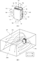
次に、図8を用いて、以上説明した構成を有する空気清浄機1が運転されているときの、空気清浄機1の動作、および、空気清浄機1が設置される部屋の空気の流れについて説明する。この図に示す例では、空気清浄機1は、図8(B)に示すように、部屋300に設置されている。部屋300は、天井面300a、床面300b、および4面の側壁面300cを備えている。空気清浄機1のリアパネル14が、側壁面300cのうちの1面に、この面に対向するように、近接して配置されている。使用者が、操作部15を操作することによって、空気清浄機1の運転が開始されると、送風機25が駆動するとともに、集塵ユニット22の第1電気集塵機22aおよび第2電気集塵機22bへの通電が開始される。さらに、加湿ユニット24の加湿フィルタ24aが、回転し始める。送風機25が駆動すると、図8(A)に示す破線矢印100のように、上面吸込口13a、右側面吸込口13b、左側面吸込口13c、および底面吸込口13dの、4方向の吸込口から、本体部11内部に空気が吸い込まれる。
本体部11内部に吸い込まれた空気は、以下のように流れる。
(1)通風路10における、脱臭ユニット23の下部と加湿ユニット24の上部とが、前後方向に重なって配置される箇所では、プレフィルタ21→集塵ユニット22→脱臭ユニット23→加湿ユニット24の順に、空気が流れる。
(2)通風路10における、脱臭ユニット23の下部と加湿ユニット24の上部とが、前後方向に重なって配置されていない箇所では、プレフィルタ21→集塵ユニット22→脱臭ユニット23の順に、または、プレフィルタ21→集塵ユニット22→加湿ユニット24の順に、空気が流れる。
このとき、プレフィルタ21、および、通電されている集塵ユニット22が、吸い込まれた空気に含まれる、塵埃および花粉を除去する。また、脱臭ユニット23が、吸い込まれた空気に含まれる臭気成分を除去する。さらに、加湿ユニット24が、吸い込まれた空気を加湿する。
(1)通風路10における、脱臭ユニット23の下部と加湿ユニット24の上部とが、前後方向に重なって配置される箇所では、プレフィルタ21→集塵ユニット22→脱臭ユニット23→加湿ユニット24の順に、空気が流れる。
(2)通風路10における、脱臭ユニット23の下部と加湿ユニット24の上部とが、前後方向に重なって配置されていない箇所では、プレフィルタ21→集塵ユニット22→脱臭ユニット23の順に、または、プレフィルタ21→集塵ユニット22→加湿ユニット24の順に、空気が流れる。
このとき、プレフィルタ21、および、通電されている集塵ユニット22が、吸い込まれた空気に含まれる、塵埃および花粉を除去する。また、脱臭ユニット23が、吸い込まれた空気に含まれる臭気成分を除去する。さらに、加湿ユニット24が、吸い込まれた空気を加湿する。
通風路10において、除塵、脱臭および加湿が施された空気は、図8(A)に示す実線矢印200のように、上面吹出口14a、右側面吹出口14b、および左側面吹出口14cの、3方向の吹出口から、空気清浄機1が設置された室内に吹き出される。このとき、各空気吹出口から吹き出された空気は、図8(B)に同じく実線矢印200によって示すように、部屋300の天井面300aあるいは側壁面300cに沿って、空気清浄機1が配置された側壁面300cの反対側の側壁面300cの側、つまり、空気清浄機1からみて部屋300の奥側に向かって流れていく。具体的には、上面吹出口14aから吹き出された空気は、天井面300aに沿って、部屋300の奥側に向かって流れていく。右側面吹出口14bから吹き出された空気は、右側の側壁面300cに沿って、部屋300の奥側に向かって流れていく。左側面吹出口14cから吹き出された空気は、左側の側壁面300cに沿って、部屋300の奥側に向かって流れていく。
以上説明したように、空気清浄機1が設置された部屋300を包み込むように、浄化および加湿された空気が吹き出される。さらに、リアパネル14が、側壁面300cに対向するように、この面に近接して配置されている、空気清浄機1は、上面吸込口13a、右側面吸込口13b、左側面吸込口13c、および底面吸込口13dの、4方向の吸込口から、部屋300の空気を吸い込む。このため、空気清浄機1は、部屋300の空気の流れを改善することが可能である。その結果、空気清浄機1は、部屋300の空気を、まんべんなく吸い込んで、除塵、加湿および脱臭することができる。また、空気清浄機1は、床面300bに付着および散乱している、塵埃、花粉、および臭気成分等を、底面吸込口13dから吸い込まれる空気とともに吸い込むことができる。このように、空気清浄機1は、床面300b上も含めた部屋300の空気の循環を改善することができる。その結果、空気清浄機1は、部屋300全体の空気を、より効果的に浄化できる。
なお、従来の空気清浄機(除塵装置)は、たとえば、特開2000-167326号公報に記載されている。この公報に記載の除塵装置では、前壁の貫通孔から、前部フィルタユニットを介して、筐体内部に空気が吸い込まれる。このため、前部フィルタユニットの背面に加えて、前部フィルタユニットの前面にも網目が設けられている。したがって、除塵装置の意匠性を高めにくい。
これに関し、本実施形態の空気清浄機1では、筐体の前面側に形成された空間の周囲に、上面吸込口13a、右側面吸込口13b、左側面吸込口13c、および底面吸込口13dが設けられている。従って、筐体の前面にあるフロントパネル13に空気吸込口が設けられないため、空気清浄機1の意匠性が向上する。
すなわち、本実施形態では、部屋の空気の循環を良くすることが可能であるとともに、比較的に高い意匠性を有する空気清浄機1を提供することができる。
これに関し、本実施形態の空気清浄機1では、筐体の前面側に形成された空間の周囲に、上面吸込口13a、右側面吸込口13b、左側面吸込口13c、および底面吸込口13dが設けられている。従って、筐体の前面にあるフロントパネル13に空気吸込口が設けられないため、空気清浄機1の意匠性が向上する。
すなわち、本実施形態では、部屋の空気の循環を良くすることが可能であるとともに、比較的に高い意匠性を有する空気清浄機1を提供することができる。
また、集塵ユニット22の空気抵抗は、プリーツ形状に形成された、不織布からなる集塵フィルタの空気抵抗に比べて、小さい。また、加熱部23fが、脱臭フィルタ23aの一部のみを覆う構造を有している。すなわち、脱臭フィルタ23aが、その一部が、通風路10に露出されるように配置されている。したがって、脱臭ユニット23の空気抵抗も、従来の触媒フィルタとほぼ同面積となるよう形成された、板形状の加熱部を有する脱臭ユニットの空気抵抗に比べて、小さい。これにより、シロッコファンよりも低い静圧を有する、ターボファン25aを、送風機25に用いることができる。
ターボファン25aを用いる場合、空気抵抗が同じなら、シロッコファンを用いる場合に比して、風量が小さくなる。しかし、ターボファン25aは、シロッコファンと比べて、高効率および高静音性を有する。このため、必要な集塵能力および脱臭能力を確保しつつ、騒音を抑制可能な、空気清浄機1を実現できる。
尚、ターボファン25aは、シロッコファンに備えられるスクロールハウジングを備えなくてもよいので、シロッコファンに比して、小型化および薄型化を図れる。このため、後述する距離Lを確保しつつ、空気清浄機1の筐体寸法が大きくなりすぎることを抑制することができる。
ターボファン25aを用いる場合、空気抵抗が同じなら、シロッコファンを用いる場合に比して、風量が小さくなる。しかし、ターボファン25aは、シロッコファンと比べて、高効率および高静音性を有する。このため、必要な集塵能力および脱臭能力を確保しつつ、騒音を抑制可能な、空気清浄機1を実現できる。
尚、ターボファン25aは、シロッコファンに備えられるスクロールハウジングを備えなくてもよいので、シロッコファンに比して、小型化および薄型化を図れる。このため、後述する距離Lを確保しつつ、空気清浄機1の筐体寸法が大きくなりすぎることを抑制することができる。
また、空気清浄機1では、集塵ユニット22および脱臭ユニット23の空気抵抗が小さい。このため、図3乃至図7に示したように、通風路10の上流側から下流側に向かって、集塵ユニット22、脱臭ユニット23、加湿ユニット24および送風機25を、この順に並べて配置した場合でも、空気清浄機1における空気抵抗が、さほど大きくならない。したがって、送風機25の駆動によって、本体部11内部の通風路10を流れる空気の量が低下しない。そして、上記のように各部材を並べて配置することによって、本体部11における前後(奥行き)方向の寸法が長くなる。さらに、本体部11の前面側に各空気吸込口が配置される一方、本体部11の背面側に、各空気吹出口が配置されている。このため、図4に示す各空気吸込口と各空気吹出口との距離Lを大きくすることができる。これにより、各空気吹出口から室内に吹き出された空気が、すぐに、各空気吸込口から空気清浄機1内部に吸い込まれるという、いわゆる空気吸込口と空気吹出口との間のショートサーキットの発生が抑制される。尚、上述したように、脱臭ユニット23より上流側に、集塵ユニット22が配置されている。このため、脱臭ユニット23に流入する空気は、塵埃および花粉等が除去された空気である。したがって、塵埃あるいは花粉等によって、脱臭ユニット23の脱臭フィルタ23aが目詰まりすることが抑制される。
さらには、図3および図4に示すように、送風機25では、各空気吸込口から各空気吹出口に向かって、ファンモータ25bおよびターボファン25aが、この順に配置されている。つまり、各空気吸込口から最も遠い場所にターボファン25aが配置されており、ターボファン25aの配置に対応して、各空気吹出口が配置されている。このため、各空気吸込口と各空気吹出口との距離Lを、より大きくすることができる。その結果、より高いショートサーキット発生の抑制効果を得られる。尚、ターボファン25aとファンモータ25bとの配置順は、上記と逆であってもよい。
なお、従来の空気清浄機は、たとえば、特開2009-22882号公報に開示されている。この公報に記載の空気清浄機では、仕切板とフロントパネルとの間に形成される、上下の空間に空気吸込口が設けられている。さらに、本体筐体の左右両側面に、空気吹出口が設けられている。したがって、ショートサーキットを抑制するために、空気吹出口を、筐体の左右両側面の最大2か所にしか設けられない。このため、空気清浄機の筐体からの、空気の放出量を十分に確保できず、十分な空気浄化能力を発揮できない可能性があった。
また、特開2009-22882号公報に記載の空気清浄機では、筐体の左右両側面に設けられた空気吹出口の両端部(上下端部)は、筐体の上下両側面に設けられた空気吸込口の近くに配置されている。このため、空気吹出口の両端部から放出された空気が、すぐに空気吸込口から筐体内部に吸い込まれる可能性がある。このため、この従来技術では、ショートサーキットを十全に抑制することは困難である。
これに関し、空気清浄機1では、上述したショートサーキットが発生しにくい距離Lを実現できる。このため、筐体の前面側に形成される、上、下、左および右の、4つの隙間を、空気清浄機1内部に空気を吸込むための、上面吸込口13a、右側面吸込口13b、左側面吸込口13c、および底面吸込口13dとすることができる。さらに、筐体の背面側に形成される、上、左および右の3つの空間を、空気清浄機1内部から空気を吹き出すための、上面吹出口14a、右側面吹出口14bおよび左側面吹出口14cとすることができる。これにより、空気吸込口および空気吹出口の面積を大きくできるので、空気の吸い込み量および吹き出し量を、十分に確保できる。
すなわち、本実施形態では、上述したように、十分な集塵能力や脱臭能力を確保するとともに、より確実にショートサーキットを抑制することできる空気清浄機1を提供することができる。
また、特開2009-22882号公報に記載の空気清浄機では、筐体の左右両側面に設けられた空気吹出口の両端部(上下端部)は、筐体の上下両側面に設けられた空気吸込口の近くに配置されている。このため、空気吹出口の両端部から放出された空気が、すぐに空気吸込口から筐体内部に吸い込まれる可能性がある。このため、この従来技術では、ショートサーキットを十全に抑制することは困難である。
これに関し、空気清浄機1では、上述したショートサーキットが発生しにくい距離Lを実現できる。このため、筐体の前面側に形成される、上、下、左および右の、4つの隙間を、空気清浄機1内部に空気を吸込むための、上面吸込口13a、右側面吸込口13b、左側面吸込口13c、および底面吸込口13dとすることができる。さらに、筐体の背面側に形成される、上、左および右の3つの空間を、空気清浄機1内部から空気を吹き出すための、上面吹出口14a、右側面吹出口14bおよび左側面吹出口14cとすることができる。これにより、空気吸込口および空気吹出口の面積を大きくできるので、空気の吸い込み量および吹き出し量を、十分に確保できる。
すなわち、本実施形態では、上述したように、十分な集塵能力や脱臭能力を確保するとともに、より確実にショートサーキットを抑制することできる空気清浄機1を提供することができる。
尚、図3の線分Pに示すように、ファンモータ25bの中心の高さを、集塵ユニット22の第1電気集塵機22aと第2電気集塵機22bとの間の空間の高さに合せるように、集塵ユニット22および送風機25を配置することが望ましい。ファンモータ25bの中心付近には、ターボファン25aの回転による、空気の流れが少ない。このため、本体部11内部における、ファンモータ25bの中心付近の空間では、空気の流れは少ないと考えられる。一方、集塵ユニット22のうち、第1電気集塵機22aと第2電気集塵機22bとの間の空間は、通過する空気に対する集塵能力が小さい。このため、この空間の高さを、ファンモータ25bの中心の高さに合わせることによって、空気の流れが多いと考えられる、ターボファン25aの羽根が存在する空間に、第1電気集塵機22aと第2電気集塵機22bとを配置することができる。これにより、集塵ユニット22による除塵を、効率的に行える。
尚、以上説明した実施形態では、空気清浄機1が、略直方体形状の筐体を有する場合を例に挙げて説明した。しかし、空気清浄機1の筐体の形状は、これに限られず、上面、底面、左側面および右側面を有し、これら各面に空気吸込口あるいは空気吹出口が設けられるような多面体形状であればよい。
また、本実施形態では、空気清浄機1が、脱臭ユニット23および加湿ユニット24の双方を備えている。しかしながら、これに限らず、空気清浄機1が、脱臭ユニット23あるいは加湿ユニット24のいずれか一方を備えるように構成されていてもよい。
また、本発明の実施形態にかかる空気清浄機は、以下の第1~第11の空気清浄機であってもよい。
第1の空気清浄機は、筐体内に空気を吸い込む空気吸込口と、筐体内から外部へ空気を吹き出す空気吹出口と、前記空気吸込口と前記空気吹出口とを連通させる通風路を備える本体部とを有し、前記本体部内に、取り込んだ空気を除塵する集塵ユニットと、取り込んだ空気を脱臭する脱臭ユニットと、送風機とを備えた空気清浄機であって、前記集塵ユニットは電気集塵機で構成され、前記脱臭ユニットは、多孔構造を有する基材に臭気成分を分解および/または吸着する脱臭層が設けられている脱臭フィルタを有し、同脱臭フィルタが前記本体部内に露出するように配置され、前記送風機は、ターボファンと、同ターボファンを回転させるファンモータとを有する。
第2の空気清浄機は、第1の空気清浄機であって、前記本体部内において、前記空気吸込口から前記空気吹出口に向かう方向に、前記集塵ユニット、前記脱臭ユニット、前記送風機の順に配置されている。
第3の空気清浄機は、第1または第2の空気清浄機において、前記脱臭層は、加熱により臭気成分の分解が促進される触媒層であり、前記脱臭ユニットは、前記脱臭フィルタの一部を覆うように形成され同脱臭フィルタを加熱する加熱手段を有する。
第4の空気清浄機は、第1~第3のいずれかの空気清浄機において、前記脱臭フィルタは、円板形状に形成されて前記本体部内に回転可能に支持されている。
第5の空気清浄機は、第1~第4のいずれかの空気清浄機において、前記空気吸込口は、本体部前面側に配置される上面吸込口、右側面吸込口、および、左側面吸込口とで構成され、前記空気吹出口は、本体部背面側に配置される上面吹出口、右側面吹出口、および、左側面吹出口とで構成される。
第6の空気清浄機は、筐体内に空気を取り込む空気吸込口と、筐体内から外部へ空気を放出する空気吹出口と、前記空気吸込口と前記空気吹出口とを連通させる送風路を備える本体部とを有し、前記本体部内に、取り込んだ空気を除塵する集塵ユニットと、取り込んだ空気を脱臭する脱臭ユニットおよび/または取り込んだ空気を加湿する加湿ユニットと、送風機とを備えた空気清浄機であって、前記本体部の前面側に配置される前面パネルと、同前面パネルの前面側に配置されるフロントパネルと、前記本体部の背面側に配置されるリアパネルとを有し、前記前面パネルと前記フロントパネルとの間に形成される間隙のうち、上端部と左右側端部とのうち少なくとも1つが前記空気吸込口とされ、前記本体部の背面と前記リアパネルとの間に形成される間隙のうち、上端部と左右側端部とが前記空気吹出口とされる。
第7の空気清浄機は、第6の空気清浄機であって、前記本体部内において、前記空気吸込口から前記空気吹出口に向かう方向に、前記集塵ユニット、前記脱臭ユニット、前記送風機の順に配置されている。
第8の空気清浄機は、第6または第7の空気清浄機において、前記送風機は、ターボファンと、同ターボファンを回転させるファンモータとを有し、前記ファンモータは、前記ターボファンより前記空気吸込口側に配置される。
第9の空気清浄機は、筐体内に空気を取り込む空気吸込口と前記筐体内から外部へ空気を放出する空気吹出口とを有し、前記筐体内に、前記空気吸込口と前記空気吹出口とを連通させる通風路を有し、前記通風路に、取り込んだ空気を除塵する集塵ユニットと送風機を有する空気清浄機であって、前記筐体は、少なくとも前面と、背面と、上面と、底面と、左側面と、右側面を有し、前記空気吸込口は、前記筐体の前面側における、前記上面と前記底面と前記左側面と前記右側面に配置され、前記空気吹出口は、前記筐体の背面側における、前記上面と前記左側面と前記右側面に配置される。
第10の空気清浄機は、第9の空気清浄機において、前記通風路に、取り込んだ空気を脱臭する脱臭ユニット、もしくは、取り込んだ空気を加湿する加湿ユニットのうち少なくとも一方を備え、前記脱臭ユニットおよび/または前記加湿ユニットは、前記集塵ユニットの下流側に配置される。
第11の空気清浄機は、第9または第10の空気清浄機において、前記筐体の背面側が、部屋の側壁面に対向するように配置して用いられる。
また、本実施形態では、空気清浄機1が、脱臭ユニット23および加湿ユニット24の双方を備えている。しかしながら、これに限らず、空気清浄機1が、脱臭ユニット23あるいは加湿ユニット24のいずれか一方を備えるように構成されていてもよい。
また、本発明の実施形態にかかる空気清浄機は、以下の第1~第11の空気清浄機であってもよい。
第1の空気清浄機は、筐体内に空気を吸い込む空気吸込口と、筐体内から外部へ空気を吹き出す空気吹出口と、前記空気吸込口と前記空気吹出口とを連通させる通風路を備える本体部とを有し、前記本体部内に、取り込んだ空気を除塵する集塵ユニットと、取り込んだ空気を脱臭する脱臭ユニットと、送風機とを備えた空気清浄機であって、前記集塵ユニットは電気集塵機で構成され、前記脱臭ユニットは、多孔構造を有する基材に臭気成分を分解および/または吸着する脱臭層が設けられている脱臭フィルタを有し、同脱臭フィルタが前記本体部内に露出するように配置され、前記送風機は、ターボファンと、同ターボファンを回転させるファンモータとを有する。
第2の空気清浄機は、第1の空気清浄機であって、前記本体部内において、前記空気吸込口から前記空気吹出口に向かう方向に、前記集塵ユニット、前記脱臭ユニット、前記送風機の順に配置されている。
第3の空気清浄機は、第1または第2の空気清浄機において、前記脱臭層は、加熱により臭気成分の分解が促進される触媒層であり、前記脱臭ユニットは、前記脱臭フィルタの一部を覆うように形成され同脱臭フィルタを加熱する加熱手段を有する。
第4の空気清浄機は、第1~第3のいずれかの空気清浄機において、前記脱臭フィルタは、円板形状に形成されて前記本体部内に回転可能に支持されている。
第5の空気清浄機は、第1~第4のいずれかの空気清浄機において、前記空気吸込口は、本体部前面側に配置される上面吸込口、右側面吸込口、および、左側面吸込口とで構成され、前記空気吹出口は、本体部背面側に配置される上面吹出口、右側面吹出口、および、左側面吹出口とで構成される。
第6の空気清浄機は、筐体内に空気を取り込む空気吸込口と、筐体内から外部へ空気を放出する空気吹出口と、前記空気吸込口と前記空気吹出口とを連通させる送風路を備える本体部とを有し、前記本体部内に、取り込んだ空気を除塵する集塵ユニットと、取り込んだ空気を脱臭する脱臭ユニットおよび/または取り込んだ空気を加湿する加湿ユニットと、送風機とを備えた空気清浄機であって、前記本体部の前面側に配置される前面パネルと、同前面パネルの前面側に配置されるフロントパネルと、前記本体部の背面側に配置されるリアパネルとを有し、前記前面パネルと前記フロントパネルとの間に形成される間隙のうち、上端部と左右側端部とのうち少なくとも1つが前記空気吸込口とされ、前記本体部の背面と前記リアパネルとの間に形成される間隙のうち、上端部と左右側端部とが前記空気吹出口とされる。
第7の空気清浄機は、第6の空気清浄機であって、前記本体部内において、前記空気吸込口から前記空気吹出口に向かう方向に、前記集塵ユニット、前記脱臭ユニット、前記送風機の順に配置されている。
第8の空気清浄機は、第6または第7の空気清浄機において、前記送風機は、ターボファンと、同ターボファンを回転させるファンモータとを有し、前記ファンモータは、前記ターボファンより前記空気吸込口側に配置される。
第9の空気清浄機は、筐体内に空気を取り込む空気吸込口と前記筐体内から外部へ空気を放出する空気吹出口とを有し、前記筐体内に、前記空気吸込口と前記空気吹出口とを連通させる通風路を有し、前記通風路に、取り込んだ空気を除塵する集塵ユニットと送風機を有する空気清浄機であって、前記筐体は、少なくとも前面と、背面と、上面と、底面と、左側面と、右側面を有し、前記空気吸込口は、前記筐体の前面側における、前記上面と前記底面と前記左側面と前記右側面に配置され、前記空気吹出口は、前記筐体の背面側における、前記上面と前記左側面と前記右側面に配置される。
第10の空気清浄機は、第9の空気清浄機において、前記通風路に、取り込んだ空気を脱臭する脱臭ユニット、もしくは、取り込んだ空気を加湿する加湿ユニットのうち少なくとも一方を備え、前記脱臭ユニットおよび/または前記加湿ユニットは、前記集塵ユニットの下流側に配置される。
第11の空気清浄機は、第9または第10の空気清浄機において、前記筐体の背面側が、部屋の側壁面に対向するように配置して用いられる。
1 空気清浄機
10 通風路
11 本体部
12 前面パネル
13 フロントパネル
13a 上面吸込口
13b 右側面吸込口
13c 左側面吸込口
13d 底面吸込口
14 リアパネル
14a 上面吹出口
14b 右側面吹出口
14c 左側面吹出口
15 操作部
21 プレフィルタ
22 集塵ユニット
22a 第1電気集塵機
22b 第2電気集塵機
23 脱臭ユニット
23aa 基材
23ab 触媒層
23a 脱臭フィルタ
23b PTCヒータ
23c 放熱板
23f 加熱部
24 加湿ユニット
24a 加湿フィルタ
24b 貯水タンク
25 送風機
25a ターボファン
25b ファンモータ
300 部屋
300c 側壁面
10 通風路
11 本体部
12 前面パネル
13 フロントパネル
13a 上面吸込口
13b 右側面吸込口
13c 左側面吸込口
13d 底面吸込口
14 リアパネル
14a 上面吹出口
14b 右側面吹出口
14c 左側面吹出口
15 操作部
21 プレフィルタ
22 集塵ユニット
22a 第1電気集塵機
22b 第2電気集塵機
23 脱臭ユニット
23aa 基材
23ab 触媒層
23a 脱臭フィルタ
23b PTCヒータ
23c 放熱板
23f 加熱部
24 加湿ユニット
24a 加湿フィルタ
24b 貯水タンク
25 送風機
25a ターボファン
25b ファンモータ
300 部屋
300c 側壁面
Claims (13)
- 筐体内に空気を取り込む空気吸込口と、
筐体内から外部へ空気を放出する空気吹出口と、
前記空気吸込口と前記空気吹出口とを連通させる通風路と、
前記通風路に備えられ、取り込んだ空気を除塵する集塵ユニットと、
前記通風路に備えられ、取り込んだ空気を脱臭する脱臭ユニットと、
前記通風路に備えられた送風機と、を備え、
前記集塵ユニットは電気集塵機を含んでおり、
前記脱臭ユニットは、多孔構造を有する基材、および、この基材に設けられ、臭気成分を分解および/または吸着する脱臭層を含む脱臭フィルタを有し、
前記脱臭フィルタが、その一部が、前記通風路に露出されるように配置され、
前記送風機は、ターボファンと、同ターボファンを回転させるファンモータとを有する、
ことを特徴とする空気清浄機。 - 前記通風路に、前記空気吸込口から前記空気吹出口に向かう方向に沿って、前記集塵ユニット、前記脱臭ユニットおよび前記送風機が、この順に配置されていることを特徴とする請求項1に記載の空気清浄機。
- 前記脱臭層は、加熱されることにより、自身に吸着されている臭気成分の分解が促進されるように構成されている触媒層であり、
前記脱臭ユニットは、前記脱臭フィルタを加熱する加熱手段を有し、
この加熱手段が、前記脱臭フィルタの一部を覆う構造を有している、
ことを特徴とする請求項1または請求項2に記載の空気清浄機。 - 前記脱臭フィルタは、円板形状を有しており、回転可能に構成されている、
ことを特徴とする請求項1~3のいずれか1項に記載の空気清浄機。 - 前記空気吸込口は、前記筐体の前面側に配置される、上面吸込口、右側面吸込口、および、左側面吸込口を含んでおり、
前記空気吹出口は、前記筐体の背面側に配置される、上面吹出口、右側面吹出口、および、左側面吹出口を含んでいる、
ことを特徴とする請求項1~4のいずれか1項に記載の空気清浄機。 - 筐体内に空気を取り込む空気吸込口と、
筐体内から外部へ空気を放出する空気吹出口と、
前記空気吸込口と前記空気吹出口とを連通させる通風路と、
前記通風路に備えられ、取り込んだ空気を除塵する集塵ユニットと、
前記通風路に備えられた送風機と、を備え、
前記筐体は、前面、背面、上面、底面、左側面および右側面を有し、
前記空気吸込口は、前記筐体の前面側における、前記上面、前記左側面および前記右側面の少なくとも1つに配置され、
前記空気吹出口は、前記筐体の背面側における、前記上面、前記左側面および前記右側面に配置される、
ことを特徴とする空気清浄機。 - 前記通風路に備えられ、取り込まれた空気を脱臭する脱臭ユニットをさらに備えている、請求項6に記載の空気清浄機。
- 前記通風路に備えられ、取り込まれた空気を加湿する加湿ユニットをさらに備えている、請求項6または7に記載の空気清浄機。
- 前記通風路に、前記空気吸込口から前記空気吹出口に向かう方向に沿って、前記集塵ユニット、前記脱臭ユニットおよび前記送風機が、この順に配置されている、
ことを特徴とする請求項7に記載の空気清浄機。 - 前記通風路に、前記空気吸込口から前記空気吹出口に向かう方向に沿って、前記集塵ユニット、前記加湿ユニットおよび前記送風機が、この順に配置されている、
ことを特徴とする請求項8に記載の空気清浄機。 - 前記送風機は、ターボファンと、前記ターボファンを回転させるファンモータとを有し、
前記ファンモータは、前記ターボファンよりも前記空気吸込口側に配置される、
ことを特徴とする請求項6~10のいずれか1項に記載の空気清浄機。 - 前記空気吸込口が、前記筐体の前面側における、前記上面、前記底面、前記左側面および前記右側面に配置される、
ことを特徴とする、請求項6~11のいずれかに記載の空気清浄機。 - 前記筐体の背面側が、部屋の側壁面に対向するように配置されて用いられる、
請求項6~12のいずれかに記載の空気清浄機。
Applications Claiming Priority (6)
| Application Number | Priority Date | Filing Date | Title |
|---|---|---|---|
| JP2014117500A JP2015230146A (ja) | 2014-06-06 | 2014-06-06 | 空気清浄機 |
| JP2014117498A JP2015230145A (ja) | 2014-06-06 | 2014-06-06 | 空気清浄機 |
| JP2014-117498 | 2014-06-06 | ||
| JP2014-117500 | 2014-06-06 | ||
| JP2014-183688 | 2014-09-09 | ||
| JP2014183688A JP6020843B2 (ja) | 2014-09-09 | 2014-09-09 | 空気清浄機 |
Publications (1)
| Publication Number | Publication Date |
|---|---|
| WO2015186804A1 true WO2015186804A1 (ja) | 2015-12-10 |
Family
ID=54766872
Family Applications (1)
| Application Number | Title | Priority Date | Filing Date |
|---|---|---|---|
| PCT/JP2015/066250 Ceased WO2015186804A1 (ja) | 2014-06-06 | 2015-06-04 | 空気清浄機 |
Country Status (4)
| Country | Link |
|---|---|
| CN (1) | CN105276696A (ja) |
| HK (1) | HK1217361A1 (ja) |
| TW (1) | TWI693367B (ja) |
| WO (1) | WO2015186804A1 (ja) |
Cited By (1)
| Publication number | Priority date | Publication date | Assignee | Title |
|---|---|---|---|---|
| JP2022518531A (ja) * | 2019-01-28 | 2022-03-15 | ブルーエアー・エービー | 空気清浄機 |
Families Citing this family (1)
| Publication number | Priority date | Publication date | Assignee | Title |
|---|---|---|---|---|
| JP2020110557A (ja) * | 2019-01-08 | 2020-07-27 | パナソニックIpマネジメント株式会社 | 空気浄化装置 |
Citations (10)
| Publication number | Priority date | Publication date | Assignee | Title |
|---|---|---|---|---|
| JP2004041954A (ja) * | 2002-07-12 | 2004-02-12 | Matsushita Ecology Systems Co Ltd | 空気清浄機 |
| JP2005233500A (ja) * | 2004-02-19 | 2005-09-02 | Daikin Ind Ltd | 空気清浄機 |
| JP2007029497A (ja) * | 2005-07-28 | 2007-02-08 | Sharp Corp | イオン発生機能付電気機器 |
| JP2008142665A (ja) * | 2006-12-12 | 2008-06-26 | Daikin Ind Ltd | 空気清浄機 |
| JP2009219531A (ja) * | 2008-03-13 | 2009-10-01 | Sanyo Electric Co Ltd | 空気清浄機 |
| JP2011002166A (ja) * | 2009-06-19 | 2011-01-06 | Panasonic Corp | 空気清浄システム |
| JP2011016072A (ja) * | 2009-07-09 | 2011-01-27 | Sanyo Electric Co Ltd | 空気清浄機 |
| JP2011179801A (ja) * | 2010-03-04 | 2011-09-15 | Panasonic Corp | 空気清浄装置および加湿機能付き空気清浄装置 |
| WO2012144346A1 (ja) * | 2011-04-21 | 2012-10-26 | 三菱電機株式会社 | 空気清浄機 |
| JP2014018326A (ja) * | 2012-07-13 | 2014-02-03 | Daikin Ind Ltd | 空気調和機 |
Family Cites Families (8)
| Publication number | Priority date | Publication date | Assignee | Title |
|---|---|---|---|---|
| CN1153680A (zh) * | 1995-10-13 | 1997-07-09 | 松田昌幸 | 利用展示流水的空气净化方法及展示兼用型空气净化装置 |
| JP2000167326A (ja) * | 1998-12-09 | 2000-06-20 | Duskin Co Ltd | 除塵装置 |
| JP2002228213A (ja) * | 2001-01-30 | 2002-08-14 | Sanyo Electric Co Ltd | 空気清浄機 |
| JP2010243068A (ja) * | 2009-04-07 | 2010-10-28 | Panasonic Corp | 加湿機能付き空気清浄機 |
| JPWO2012144342A1 (ja) * | 2011-04-21 | 2014-07-28 | 三菱電機株式会社 | 空気清浄機 |
| JP6020805B2 (ja) * | 2012-09-05 | 2016-11-02 | 株式会社富士通ゼネラル | 空気清浄機 |
| CN202993374U (zh) * | 2012-09-25 | 2013-06-12 | 广东美的制冷设备有限公司 | 后部回风、前部上下送风的空调器室内机 |
| CN103791545B (zh) * | 2014-01-13 | 2016-01-13 | 河南师范大学 | 一种具有空气净化功能的对流式电暖器 |
-
2015
- 2015-03-26 CN CN201510137841.1A patent/CN105276696A/zh active Pending
- 2015-06-04 WO PCT/JP2015/066250 patent/WO2015186804A1/ja not_active Ceased
- 2015-06-08 TW TW104118540A patent/TWI693367B/zh not_active IP Right Cessation
-
2016
- 2016-05-09 HK HK16105258.8A patent/HK1217361A1/zh unknown
Patent Citations (10)
| Publication number | Priority date | Publication date | Assignee | Title |
|---|---|---|---|---|
| JP2004041954A (ja) * | 2002-07-12 | 2004-02-12 | Matsushita Ecology Systems Co Ltd | 空気清浄機 |
| JP2005233500A (ja) * | 2004-02-19 | 2005-09-02 | Daikin Ind Ltd | 空気清浄機 |
| JP2007029497A (ja) * | 2005-07-28 | 2007-02-08 | Sharp Corp | イオン発生機能付電気機器 |
| JP2008142665A (ja) * | 2006-12-12 | 2008-06-26 | Daikin Ind Ltd | 空気清浄機 |
| JP2009219531A (ja) * | 2008-03-13 | 2009-10-01 | Sanyo Electric Co Ltd | 空気清浄機 |
| JP2011002166A (ja) * | 2009-06-19 | 2011-01-06 | Panasonic Corp | 空気清浄システム |
| JP2011016072A (ja) * | 2009-07-09 | 2011-01-27 | Sanyo Electric Co Ltd | 空気清浄機 |
| JP2011179801A (ja) * | 2010-03-04 | 2011-09-15 | Panasonic Corp | 空気清浄装置および加湿機能付き空気清浄装置 |
| WO2012144346A1 (ja) * | 2011-04-21 | 2012-10-26 | 三菱電機株式会社 | 空気清浄機 |
| JP2014018326A (ja) * | 2012-07-13 | 2014-02-03 | Daikin Ind Ltd | 空気調和機 |
Cited By (3)
| Publication number | Priority date | Publication date | Assignee | Title |
|---|---|---|---|---|
| JP2022518531A (ja) * | 2019-01-28 | 2022-03-15 | ブルーエアー・エービー | 空気清浄機 |
| JP7480157B2 (ja) | 2019-01-28 | 2024-05-09 | ブルーエアー・エービー | 空気清浄機 |
| US12163694B2 (en) | 2019-01-28 | 2024-12-10 | Blueair Ab | Air purifier |
Also Published As
| Publication number | Publication date |
|---|---|
| HK1217361A1 (zh) | 2017-01-06 |
| TWI693367B (zh) | 2020-05-11 |
| CN105276696A (zh) | 2016-01-27 |
| TW201600812A (zh) | 2016-01-01 |
Similar Documents
| Publication | Publication Date | Title |
|---|---|---|
| JP5999149B2 (ja) | 空気清浄機 | |
| CN108686510A (zh) | 吸附单元及空气净化器 | |
| JP5958507B2 (ja) | 空気清浄機 | |
| JP5900562B1 (ja) | 空気清浄機 | |
| WO2015186804A1 (ja) | 空気清浄機 | |
| WO2016031782A1 (ja) | 空気清浄機 | |
| JP6281593B2 (ja) | 空気清浄機 | |
| JP6020805B2 (ja) | 空気清浄機 | |
| JP6020843B2 (ja) | 空気清浄機 | |
| JP6229772B1 (ja) | 吸着ユニットおよび空気清浄機 | |
| JP2006017425A (ja) | 空気調和機 | |
| JP6405802B2 (ja) | 空気清浄機 | |
| JP6848347B2 (ja) | 吸着ユニットおよび空気清浄機 | |
| JP2015230146A (ja) | 空気清浄機 | |
| JP2016052496A (ja) | 空気清浄機 | |
| JP6405798B2 (ja) | 空気清浄機 | |
| JP2015230145A (ja) | 空気清浄機 | |
| JP2016056985A (ja) | 空気調和機 | |
| JP2017106674A (ja) | 空気清浄機 | |
| JP2018153744A (ja) | 吸着ユニット及び空気清浄機 | |
| JP6996149B2 (ja) | 吸着ユニット及び空気清浄機 | |
| HK1230699B (zh) | 空气净化器 | |
| JP2017096602A (ja) | 空気清浄機 | |
| HK1230699A1 (en) | Air purifier | |
| JP2017044425A (ja) | 空気調和機 |
Legal Events
| Date | Code | Title | Description |
|---|---|---|---|
| 121 | Ep: the epo has been informed by wipo that ep was designated in this application |
Ref document number: 15803822 Country of ref document: EP Kind code of ref document: A1 |
|
| NENP | Non-entry into the national phase |
Ref country code: DE |
|
| 122 | Ep: pct application non-entry in european phase |
Ref document number: 15803822 Country of ref document: EP Kind code of ref document: A1 |