WO2015186783A1 - 光計測用チャンバ及び光計測装置 - Google Patents
光計測用チャンバ及び光計測装置 Download PDFInfo
- Publication number
- WO2015186783A1 WO2015186783A1 PCT/JP2015/066174 JP2015066174W WO2015186783A1 WO 2015186783 A1 WO2015186783 A1 WO 2015186783A1 JP 2015066174 W JP2015066174 W JP 2015066174W WO 2015186783 A1 WO2015186783 A1 WO 2015186783A1
- Authority
- WO
- WIPO (PCT)
- Prior art keywords
- space
- light
- excitation light
- optical measurement
- chamber
- Prior art date
- Legal status (The legal status is an assumption and is not a legal conclusion. Google has not performed a legal analysis and makes no representation as to the accuracy of the status listed.)
- Ceased
Links
Images








Classifications
-
- G—PHYSICS
- G01—MEASURING; TESTING
- G01N—INVESTIGATING OR ANALYSING MATERIALS BY DETERMINING THEIR CHEMICAL OR PHYSICAL PROPERTIES
- G01N21/00—Investigating or analysing materials by the use of optical means, i.e. using sub-millimetre waves, infrared, visible or ultraviolet light
- G01N21/01—Arrangements or apparatus for facilitating the optical investigation
- G01N21/03—Cuvette constructions
-
- G—PHYSICS
- G01—MEASURING; TESTING
- G01N—INVESTIGATING OR ANALYSING MATERIALS BY DETERMINING THEIR CHEMICAL OR PHYSICAL PROPERTIES
- G01N21/00—Investigating or analysing materials by the use of optical means, i.e. using sub-millimetre waves, infrared, visible or ultraviolet light
- G01N21/62—Systems in which the material investigated is excited whereby it emits light or causes a change in wavelength of the incident light
- G01N21/63—Systems in which the material investigated is excited whereby it emits light or causes a change in wavelength of the incident light optically excited
- G01N21/64—Fluorescence; Phosphorescence
-
- G—PHYSICS
- G01—MEASURING; TESTING
- G01N—INVESTIGATING OR ANALYSING MATERIALS BY DETERMINING THEIR CHEMICAL OR PHYSICAL PROPERTIES
- G01N21/00—Investigating or analysing materials by the use of optical means, i.e. using sub-millimetre waves, infrared, visible or ultraviolet light
- G01N21/62—Systems in which the material investigated is excited whereby it emits light or causes a change in wavelength of the incident light
- G01N21/63—Systems in which the material investigated is excited whereby it emits light or causes a change in wavelength of the incident light optically excited
- G01N21/65—Raman scattering
Definitions
- the present invention relates to an optical measurement chamber and an optical measurement device.
- a chamber having an inlet for introducing a sample and an outlet for discharging the sample is provided, and light such as Raman light (Raman scattered light) is generated by irradiating the sample with excitation light in the chamber.
- light such as Raman light (Raman scattered light)
- an optical measurement device that detects the above with a photodetector (for example, Patent Documents 1 to 5).
- the optical path length of the excitation light is increased by using a resonator-like cavity structure.
- Patent Document 1 describes an optical analyzer including a chamber having a cavity constituted by two concave mirrors arranged so as to sandwich a focal point.
- this optical analyzer when laser light is irradiated from the vicinity of the end of one concave mirror, the laser light reciprocates between the concave mirrors several tens of times and escapes from the cavity. During this time, Raman light is generated at the focal point of the concave mirror, and a part of the light is guided to the photodetector by the lens.
- the present invention provides an optical measurement chamber and an optical measurement device capable of improving the light generation efficiency and detection efficiency without increasing the size.
- the optical measurement chamber is an optical measurement chamber for generating light by causing an excitation light and a sample to interact with each other.
- the optical measurement chamber includes a space forming portion in which a cylindrical space extending in one direction is formed, and a reflecting portion provided on a pair of face portions facing each other among inner surfaces defining the space of the space forming portion, A sample is introduced into a window provided at one end in one direction of the space, a closed portion provided at the other end in one direction of the space, and an area of the space separated by the window and the closed portion.
- An introduction unit, and a discharge unit that discharges the sample from the region.
- the space includes a first space and a second space arranged along one direction.
- the pair of surface portions extend from the window portion to the closing portion.
- the pair of surface portions in the first space are inclined so that the distance from each other decreases from one end side to the other end side, and the first angle formed between each of the pair of surface portions in the first space and one direction is The second angle formed by each of the pair of surface portions in the second space and the one direction is larger.
- the number of reflections of the excitation light in the second space increases by increasing the angle between the traveling direction of the excitation light and the one direction in the first space.
- the optical path length of the excitation light in the two spaces is increased.
- the light generated toward one end side of the space is emitted from one end of the space in the region divided by the window portion and the blocking portion.
- the angle formed by the traveling direction of the light and the one direction decreases by twice the first angle.
- the light emitted from the optical measurement chamber can have a smaller angle between the traveling direction and one direction compared to when it is generated in the region, thereby improving the light orientation and Detection efficiency can be improved.
- the pair of surface portions in the second space may extend in parallel along one direction. Even in this case, since the number of reflections of the excitation light in the second space increases by increasing the angle between the traveling direction of the excitation light and the one direction in the first space, the optical path length of the excitation light in the second space is increased. Becomes longer. Thereby, in the area
- the blocking portion may be a light reflecting portion that reflects excitation light.
- the excitation light that has entered the space from one end of the space is repeatedly reflected by the reflecting portion in the first space and the second space, and then is reflected by the light reflecting portion toward the one end side of the space. Is incident again. And excitation light is radiate
- the excitation light reciprocates in the space, the opportunity for interaction between the excitation light and the sample is further increased in the region partitioned by the window portion and the light reflection portion. As a result, the light generation efficiency can be further improved.
- the region divided by the window portion and the light reflecting portion light is generated in all directions, but the light generated toward the other end side of the space is reflected by the light reflecting portion and is one end of the space. Emanates from. In this way, the light generated in the region is oriented to one end side of the space and is emitted from one end of the space through the first space, so that the light orientation is further improved and the light detection efficiency is further improved. It becomes possible.
- the closed portion may be another window portion that can transmit excitation light.
- optical measurement such as Raman light
- the closed portion by using the closed portion as another window portion, the excitation light incident on the space from one end of the space is repeatedly reflected by the reflecting portion in the first space and the second space, and then the other window portion is used.
- the light is transmitted and emitted from the other end of the space to the outside of the optical measurement chamber.
- the blocking part may be provided with an antireflection structure on the part facing the area of the blocking part and on the opposite side.
- an antireflection structure on the part facing the area of the blocking part and on the opposite side.
- the space may further include a third space, and the first space, the second space, and the third space may be arranged along one direction in that order.
- the pair of surface portions in the third space are inclined so that the distance from each other increases from one end side to the other end side, and the third angle formed between each of the pair of surface portions in the third space and one direction is The angle may be larger than the second angle.
- the angle formed by the traveling direction of the excitation light and the one direction is determined by each of the pair of surface portions in the third space. Decreases by twice the third angle formed by one direction.
- the blocking part may be a light absorbing part capable of absorbing excitation light.
- the excitation light that has entered the space from one end of the space is repeatedly reflected by the reflection unit in the first space and the second space, and then absorbed by the light absorption unit, the excitation light is externally transmitted from one end side of the space. Can be prevented from being emitted.
- the photodetector provided at one end of the space, the possibility that the excitation light is detected by the photodetector can be reduced. It is possible to reduce the measurement background.
- the space may further include a fourth space larger than the second space, and the first space, the second space, and the fourth space may be arranged in one direction in that order.
- the excitation light that has entered the space from one end of the space is repeatedly reflected by the reflecting portion in the first space and the second space, and then enters the fourth space and absorbs light while being repeatedly reflected in the fourth space. Absorbed by the part.
- the fourth space is larger than the second space, it is possible to reduce the probability that the excitation light in the fourth space is incident again on the second space, and that the excitation light is emitted from one end side of the space to the outside. Can be suppressed.
- the possibility that the excitation light is detected by the photodetector can be further reduced.
- the background of optical measurement can be further reduced.
- the pair of surface portions may be flat.
- the excitation light diffuses when irradiated with the excitation light.
- it is a flat surface
- the diffusion of the excitation light can be reduced.
- the polishing accuracy can be improved as compared with the concave surface.
- An optical measurement device includes the above-described optical measurement chamber, an excitation light supply device that supplies excitation light from one end side to the space of the optical measurement chamber, and light generated in the optical measurement chamber. And a photodetector for detecting light emitted from one end side.
- optical measuring device it is possible to improve the light generation efficiency without increasing the size of the optical measuring device by providing the above-described optical measuring chamber. Further, by providing the above-described optical measurement chamber, the orientation of light is improved, so that the light detection efficiency by the photodetector can be improved.
- An optical measurement chamber is an optical measurement chamber for generating light by causing excitation light and a sample to interact with each other.
- the optical measurement chamber is provided on one end side in one direction of the space, a space forming portion in which a cylindrical space extending in one direction is formed, a reflecting portion that covers an inner surface that defines the space of the space forming portion.
- the space includes a first space and a second space arranged along one direction.
- the area of the opening formed by the inner surface defining the first space is different from one end side.
- the first angle that is smaller toward the end side and that is formed by the inner surface that defines the first space and one direction is larger than the second angle that is formed by the inner surface that defines the second space and the one direction.
- the excitation light when excitation light is incident at a predetermined angle with respect to one direction from one end of the space, the excitation light is incident on the second space while being repeatedly reflected by the reflecting portion in the first space.
- the angle formed by the traveling direction of the excitation light and the one direction increases by twice the first angle formed by the inner surface defining the first space and the one direction. For this reason, the excitation light is incident on the second space at an angle larger than a predetermined angle with respect to one direction.
- excitation light is repeatedly reflected by the reflecting portion in the second space
- the excitation light travels toward the other end side of the space, is reflected by the light reflecting portion, travels toward the one end side of the space, and is incident on the first space again.
- excitation light is radiate
- the number of reflections of the excitation light in the second space increases by increasing the angle between the traveling direction of the excitation light and the one direction in the first space.
- the optical path length of the excitation light in the two spaces is increased.
- the light generated in the region divided by the window and the light reflecting portion light is generated in all directions, but the light generated toward one end of the space is emitted from one end of the space and is transmitted to the other end of the space.
- the light generated toward the surface is reflected by the light reflecting portion and is emitted from one end of the space.
- the light generated in the region is oriented toward one end of the space, and exits from one end of the space through the first space.
- the angle formed by the traveling direction of the light and the one direction decreases by twice the first angle. For this reason, the light emitted from the optical measurement chamber can have a smaller angle between the traveling direction and one direction compared to when it is generated in the region, thereby improving the light orientation and Detection efficiency can be improved.
- the first space may be a tapered space
- the second space may be a cylindrical space.
- the window may be provided in the first space.
- the excitation light is incident at a predetermined angle so that the reflectance at the window portion becomes small, the excitation light is reflected by the reflection portion in the first space, so that the excitation light travels in one direction. The angle between and increases. For this reason, since the frequency
- the introduction part may be provided on the window part side, and the discharge part may be provided on the light reflection part side. Since the excitation light has a large amount of light on the window side, by providing the introduction part on the window side, diffusion of the sample can be suppressed in a region where the amount of excitation light is large, which further improves the light generation efficiency. It becomes possible.
- the introduction unit may introduce a sample that generates Raman light by interacting with excitation light.
- the generation efficiency and detection efficiency of Raman light can be improved without increasing the size of the optical measurement chamber.
- the introduction unit may introduce a sample that generates fluorescence by interacting with excitation light.
- the generation efficiency and detection efficiency of fluorescence can be improved without increasing the size of the optical measurement chamber.
- An optical measurement device is generated in the above-described optical measurement chamber, an excitation light supply device that supplies excitation light from one end side to the space of the optical measurement chamber, and the optical measurement chamber A light detector for detecting light emitted from one end side of the light.
- optical measuring device it is possible to improve the light generation efficiency without increasing the size of the optical measuring device by providing the above-described optical measuring chamber. Further, by providing the above-described optical measurement chamber, the orientation of light is improved, so that the light detection efficiency by the photodetector can be improved.
- the excitation light supply device supplies the excitation light to the space at an incident angle set so that the excitation light reflected by the light reflecting portion of the optical measurement chamber is emitted in a different direction from the photodetector. Good. In this case, it is possible to prevent the excitation light from being detected by the photodetector and improve the detection accuracy of the light generated in the optical measurement chamber.
- the excitation light supply device may supply the excitation light to the space at an incident angle set so that the excitation light is incident on the window portion at a Brewster angle.
- light generation efficiency and detection efficiency can be improved without increasing the size.
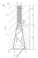
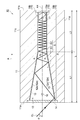
- FIG. 6 is a cross-sectional view taken along a direction A schematically showing a modification of the optical measurement chamber of FIG. 1.
- FIG. 10 is a cross-sectional view along direction A schematically showing another modification of the optical measurement chamber of FIG. 1.
- FIG. 11 is a cross-sectional view along direction A schematically showing a modification of the optical measurement chamber of FIG. 10. It is a figure which shows schematically the optical measuring device provided with the chamber for optical measurement which concerns on 4th Embodiment. It is sectional drawing along the direction A which shows the chamber for optical measurement of FIG. 13 roughly.
- FIG. 14 is a cross-sectional view along a direction A schematically showing a modification of the optical measurement chamber of FIG. 13. It is a figure for demonstrating the optical path length of the chamber for optical measurement. It is sectional drawing along the direction A which shows the chamber for optical measurement of a comparative example roughly.
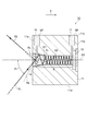
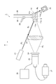
- FIG. 1 is a diagram schematically illustrating an optical measurement device including an optical measurement chamber according to the first embodiment.
- the optical measurement device 1 includes a chamber 10, an excitation light supply device 21, an excitation light absorption device 22, a condensing lens 23, an optical filter 24, a photodetector 25, and a power source. 26, an amplifier 27, an introduction pipe 28, and a discharge pipe 29.
- the optical measurement device 1 is a device for measuring the light RL generated in the chamber 10 by supplying a sample to the chamber 10 and irradiating the excitation light EL.
- the chamber 10 is an optical measurement chamber for generating the light RL by causing the excitation light EL and the sample to interact with each other.
- the chamber 10 is provided with a space S extending in the direction A (one direction) from the surface 11a, and an opening 11e that is an open end of the space S is formed in the surface 11a. Details of the chamber 10 will be described later.
- the excitation light supply device 21 is a device that supplies excitation light EL such as laser light to the space S of the chamber 10 from the surface 11a side (one end side).
- the excitation light supply device 21 is provided to face the surface 11 a of the chamber 10.
- the excitation light absorbing device 22 is a device for absorbing the excitation light EL emitted from the chamber 10, and is, for example, a beam stop element.
- the excitation light absorbing device 22 is provided to face the surface 11 a of the chamber 10.
- the excitation light absorption device 22 is, for example, the excitation light with respect to the axis AX (see FIG. 2) of the space S. It is arranged on the opposite side of the supply device 21.
- the condenser lens 23 is a lens for guiding the light RL emitted from the chamber 10 to the photodetector 25.
- the condensing lens 23 is provided to face the opening 11e of the chamber 10, and is disposed, for example, at a position 50 mm from the surface 11a of the chamber 10.
- the f value of the condenser lens 23 is, for example, 25 mm, and the diameter of the condenser lens 23 is, for example, 1 inch.
- the optical filter 24 is a filter that transmits light in a specific wavelength region so that the photodetector 25 can detect specific light.
- the optical filter 24 is provided between the condenser lens 23 and the photodetector 25.
- the photodetector 25 is a device that detects the light RL emitted from the surface 11a out of the light RL generated in the chamber 10, and is, for example, a photomultiplier tube (PMT).
- the photodetector 25 outputs a current according to the intensity of the detected light RL.
- the power source 26 is a high voltage power source for operating the photodetector 25.
- the amplifier 27 is an amplifier that converts the current output from the photodetector 25 into a voltage.
- the introduction tube 28 is connected to the chamber 10 and is a tube for introducing a sample into the chamber 10.
- the introduction pipe 28 is provided with a flow rate adjusting mechanism 30 (for example, a regulator or the like) for adjusting the amount of sample introduced.
- the discharge pipe 29 is connected to the chamber 10 and is a pipe for discharging the sample from the chamber 10.
- a sample such as a gas, a liquid, or a biological sample is supplied to the space S of the chamber 10 through the introduction pipe 28, and the excitation light supply device 21 faces the opening 11 e on the surface 11 a of the chamber 10.
- Excitation light EL is irradiated. Then, the excitation light EL reciprocates in the space S in the chamber 10, exits from the opening 11 e of the chamber 10, and is absorbed by the excitation light absorber 22.
- the interaction between the excitation light EL and the sample in the chamber 10 generates, for example, light RL such as Raman light or fluorescence, and part of the generated light RL is The light is emitted from the opening 11e to the outside of the chamber 10. Then, the light RL emitted from the chamber 10 is collected by the condenser lens 23 and guided to the photodetector 25 through the optical filter 24 and detected.
- light RL such as Raman light or fluorescence
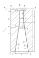
- FIG. 2 is a cross-sectional view along the direction A schematically showing the chamber 10.
- the chamber 10 includes a main body part 11, a space forming part 12, a reflecting part 13, a window part 14, a light reflecting part 15 (blocking part), an introducing part 16, and a discharging part. 17.
- the main body 11 has a box shape extending in the direction A, and is made of, for example, SUS material.
- the main body 11 has a surface 11a, a surface 11b, a surface 11c, and a surface 11d.
- the surface 11a and the surface 11b are surfaces that intersect the direction A, and the surface 11c and the surface 11d are surfaces that intersect the surface 11a and the surface 11b.
- the direction in which the surface 11a is provided is “front”
- the direction in which the surface 11b is provided is “rear”
- the direction in which the surface 11c is provided is “up”
- the surface 11d is provided.
- the direction in which it is located may be “down”.
- the space forming portion 12 is a portion in which a cylindrical space S extending in the direction A is formed.
- the space S is defined by a cylindrical inner surface 12 a with the axis AX along the direction A as an axis, and forms an opening 11 e in the surface 11 a of the main body 11.
- the space S includes a first space S1 and a second space S2 arranged in order along the direction A.
- the first space S1 is a tapered space with the axis AX as an axis
- the second space S2 is a cylindrical space with the axis AX as an axis.
- the tapered shape includes a substantially tapered shape
- the cylindrical shape includes a substantially cylindrical shape.
- the diameter of the cross section intersecting the axis AX decreases, and the first space S1 continues to the second space S2. That is, in the cross section intersecting with the direction A, the area of the opening formed by the inner surface 12a defining the first space S1 decreases from the front side (one end side) to the rear side (the other end side). For this reason, in the first space S1, the area of the opening 11e is the largest, and the area of the cross section orthogonal to the axis AX at the connection portion with the second space S2 is the smallest.
- the length L1 along the direction A of the first space S1 is, for example, about 11 mm
- the diameter D1 (that is, the diameter of the opening 11e) in the surface 11a of the first space S1 is, for example, about 3 mm
- the diameter at the connecting portion with the second space S2 is, for example, about 1 mm.
- the length L2 along the direction A of the second space S2 is, for example, about 5 mm
- the diameter D2 of the second space S2 is, for example, about 1 mm.
- the angle ⁇ (first angle) formed by the inner surface 12a defining the first space S1 and the direction A, that is, the taper angle, is the direction of the inner surface 12a defining the second space S2. It is larger than the angle ⁇ (second angle) formed by A.
- the angle ⁇ is about 5 degrees, for example, and the angle ⁇ is about 0 degrees, for example. The above is an example because the optimal size of the chamber 10 differs for each application.
- the reflection unit 13 is a mirror surface that reflects light, and is made of, for example, gold (Au).
- Reflecting portion 13 may be constituted by an aluminum protective film of MgF 2 or the like thereon may be coated.
- the reflecting portion 13 is provided so as to cover the inner surface 12 a that defines the space S of the space forming portion 12.
- the window 14 is an optical window that transmits the excitation light and the light generated in the chamber 10, and is made of, for example, optical glass.
- the window portion 14 is provided on the front side of the space S, and closes the space S on the front side.
- the window part 14 is located in 1st space S1, for example.
- the light reflecting portion 15 is a mirror that reflects light, and is made of, for example, gold (Au) or aluminum.
- the light reflecting portion 15 is provided on the rear side of the space S and closes the other end of the space S.
- the introduction part 16 is a part for introducing the sample into the region R of the space S that is partitioned by the window part 14 and the light reflection part 15.
- the introduction part 16 is a through hole extending from the surface 11c toward the surface 11d to the region R of the space S, and is provided, for example, on the window portion 14 side of the region R.
- the introduction unit 16 is connected to the introduction tube 28 and introduces, for example, a sample for generating Raman light or fluorescence by interacting with excitation light.
- the discharge part 17 is a part for discharging the sample from the region R.
- the discharge portion 17 is a through-hole extending from the surface 11c toward the surface 11d to the region R of the space S, and is provided on the light reflection portion 15 side of the region R, for example.
- the discharge unit 17 is connected to the discharge pipe 29 and discharges the sample in the region R through the discharge pipe 29.
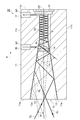
- FIG. 3 is a diagram illustrating an example of an optical path in the chamber 10.
- FIG. 4 is a diagram illustrating an example of the intensity distribution of the excitation light EL in the second space S2.
- the sample SP is introduced into the region R by the introduction unit 16, and the sample SP is ejected from the region R by the ejection unit 17. Thereby, the sample SP flows in the region R of the chamber 10 one after another.
- the sample SP to be introduced include a gas for generating Raman light and a liquid (fluorescent label sample) for generating fluorescence. In this state, excitation light EL enters from the outside of the chamber 10.
- Excitation light EL is incident from the surface 11a side of the main body portion 11 in the space S of the chamber 10 at an angle theta 1 with respect to the axis AX.
- the angle ⁇ 1 is 26 degrees in this example.
- excitation light EL goes to the window part 14, repeating reflection by the reflection part 13 in 1st space S1.
- the angle formed between the traveling direction of the excitation light EL and the axis AX increases by twice the angle ⁇ .
- the excitation light EL is incident on the window portion 14 at an angle theta 2 to the axis AX.
- the angle ⁇ 2 is larger than the angle ⁇ 1 and is 56 degrees in this example.
- the excitation light EL is repeatedly reflected by the reflecting portion 13 in the first space S1 in the region R, and the angle formed by the traveling direction of the excitation light EL and the axis AX further increases.
- the excitation light EL is incident on the second space S2 at an angle theta 3 with respect to the axis AX.
- the angle ⁇ 3 is larger than the angle ⁇ 2 , which is 86 degrees in this example, and is preferably not less than 80 degrees and less than 90 degrees.
- the angle ⁇ and the angle ⁇ 1 are adjusted so that the excitation light EL is incident on the second space S2 at an angle ⁇ 3 with respect to the axis AX.
- the excitation light EL travels toward the light reflecting portion 15 while being repeatedly reflected by the reflecting portion 13 in the second space S2. And it reflects by the light reflection part 15, and goes to the window part 14, repeating reflection by the reflection part 13 in 2nd space S2.
- the excitation light EL is incident on the reflecting portion 13 at an angle theta 3, are reflected at an angle theta 3. That is, since the second space S2 is a cylindrical shape with the axis AX and the axis, the reflection of the reflective portion 13 in the second space S2, the traveling direction and the angle formed between the axis AX of the excitation light EL is maintained an angle theta 3 To do.
- the excitation light EL is repeatedly reflected by the reflecting portion 13 in the first space S1 in the region R.
- the angle formed between the traveling direction of the excitation light EL and the axis AX decreases by twice the angle ⁇ .
- the excitation light EL passes through the window portion 14 and further travels toward the surface 11 a of the main body portion 11 while being repeatedly reflected by the reflecting portion 13. Then, the excitation light EL is emitted to the outside of the chamber 10 from the surface 11a.
- the excitation light EL so emitted at an angle theta 1 with respect to the axis AX, so as to emit in a direction different from the incident direction of the excitation light EL, a length along the direction A of the first space S1 L1 , angle between the inner surface 12a and the direction a defining a first space S1 is alpha, the diameter D1 of the opening 11e, the angle theta 1 is pre-adjusted with respect to the axis AX of the excitation light EL.
- the interaction between the excitation light EL and the sample SP in the region R causes the light RL in each part of the optical path of the excitation light EL. Occurs.
- the light amount (optical power) of the excitation light EL decreases as the excitation light EL proceeds while being repeatedly reflected in the space S in the chamber 10.
- the region R the total light amount of the excitation light EL in the forward path and the return path gradually decreases from the front end to the rear end of the second space S2, but light RL can be generated in the entire region R. Further, the light RL generated in the region R can be generated in all directions (solid angle 4 ⁇ ).
- the light RL generated toward the front passes through the window portion 14 and is emitted from the opening 11e while being repeatedly reflected by the reflecting portion 13. Further, the light RL generated toward the rear proceeds toward the light reflecting portion 15 while being repeatedly reflected by the reflecting portion 13. Then, the light RL is reflected by the light reflecting portion 15 and is transmitted through the window portion 14 while being repeatedly reflected by the reflecting portion 13 and is emitted from the opening 11e. In this way, the light RL is oriented forward.
- the light RL generated in the region R is emitted to the outside of the chamber 10 through the first space S1.
- the angle formed between the traveling direction of the light RL and the axis AX decreases by twice the angle ⁇ .
- the light RL emitted from the chamber 10 can be smaller in angle formed by the traveling direction and the axis AX than the light RL generated in the region R, so that the solid angle less than 2 ⁇ is from the chamber 10.
- the number of reflections of the excitation light EL in the second space S2 increases by increasing the angle formed between the traveling direction of the excitation light EL and the direction A in the first space S1. Therefore, the optical path length of the excitation light EL (interaction length between the excitation light EL and the sample SP) in the second space S2 becomes long. Thereby, in the area
- the light RL is generated in all directions, but the light generated toward the front of the space S is emitted from the opening 11e, and the light RL generated toward the rear of the space S is reflected by light.
- the light is reflected by the portion 15 and exits from the opening 11e.
- the light RL generated in the region R is oriented in front of the space S.
- the angle formed by the traveling direction of the light RL and the axis AX decreases by twice the angle ⁇ . For this reason, the angle between the traveling direction and the axis AX of the light RL emitted from the chamber 10 can be smaller than that generated when the light is generated in the region R. It becomes possible to improve the detection efficiency of RL.
- the window part 14 is provided in 1st space S1. Therefore, as the reflectance decreases at the window portion 14, even if the excitation light EL as entering the window 14 at an angle theta 2 to the axis AX, the reflective portion 13 of the first space S1 in the region R By reflecting the excitation light EL, the angle formed between the traveling direction of the excitation light EL and the axis AX increases. Thus, the excitation light EL may be at an angle greater theta 3 than the angle theta 2 to the axis AX enters the second space S2, the second space excitation light EL at an angle theta 2 to the axis AX The optical path length of the excitation light EL in the second space S2 becomes longer than when incident on S2. That is, since the optical path length of the excitation light EL in the second space S2 can be increased while reducing the reflection of the excitation light EL in the window portion 14, the efficiency of generating the light RL in the chamber 10 can be further improved.
- the introduction part 16 is provided on the window part 14 side, and the discharge part 17 is provided on the light reflection part 15 side.
- the excitation light EL has a large amount of light on the window 14 side. For this reason, by providing the introduction part 16 on the window part 14 side, diffusion of the sample SP can be suppressed in a region where the light amount of the excitation light EL is large, and the generation efficiency of the light RL can be further improved.
- the excitation light supply device 21 is configured so that the excitation light EL reflected by the light reflecting portion 15 of the chamber 10 is incident on the excitation light EL at an incident angle ⁇ 1 set so as to be emitted in a direction different from the photodetector 25. Is supplied to the space S. For this reason, it is possible to prevent the excitation light EL from being detected by the photodetector 25 and to improve the detection accuracy of the light RL.
- the excitation light supply device 21 may supply the excitation light EL to the space S at an incident angle ⁇ 1 set so that the excitation light EL is incident on the window portion 14 at a Brewster angle.
- the transmittance of the excitation light EL in the window portion 14 can be improved, and a decrease in the light amount of the excitation light EL supplied to the region R can be suppressed. For this reason, the generation efficiency of the light RL can be further improved.
- the length L1 of the first space S1 may be shorter than the chamber 10 of FIG.
- the length L along the direction A of the chamber 10 may be about 6 mm.
- the chamber 10 can be further reduced in size, and the manufacture of the chamber 10 is facilitated.
- the first space S1 is shorter than the chamber 10 of FIG. 1, so that the light RL is reflected by the reflecting portion 13 in the first space S1.
- Opportunities decrease. Therefore, the angle between the traveling direction and the axis AX of the light RL emitted from the chamber 10 is larger than that of the chamber 10 of FIG. Further, it is necessary to enter the chamber 10 at an angle (for example, Brewster angle) that is larger than the angle ⁇ 1 with respect to the axis AX.
- an angle for example, Brewster angle
- FIG. 7 a configuration in which the window portion 14 and the introduction portion 16 are arranged immediately after the opening 11e in the chamber 10 of FIG.
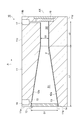
- FIG. 8 is a cross-sectional view along direction A schematically showing the optical measurement chamber according to the second embodiment.
- FIG. 9 is a view as seen from the direction A of the optical measurement chamber of FIG.
- the chamber 10 of the second embodiment is different from the first embodiment in the shape of the space forming portion 12, the arrangement of the reflecting portion 13, and the arrangement of the introducing portion 16 and the discharging portion 17. This is different from the chamber 10.
- the inner surface 12a defining the space S includes an upper inner surface 12b, a lower inner surface 12c, a side inner surface 12d, and a side inner surface 12e.
- the upper inner surface 12 b and the lower inner surface 12 c (a pair of surface portions) are flat and extend from the window portion 14 to the light reflecting portion 15.
- the upper inner surface 12b and the lower inner surface 12c face each other across the axis AX, the upper inner surface 12b is located above the axis AX, and the lower inner surface 12c is located below the axis AX.
- the upper inner surface 12b and the lower inner surface 12c extend at an angle with respect to the axis AX from the surface 11a toward the surface 11b in a portion that defines the first space S1, and the distance from each other as the surface 11a proceeds from the surface 11a to the surface 11b. Is getting smaller.
- the upper inner surface 12b and the lower inner surface 12c extend substantially parallel to the axis AX at a portion that defines the second space S2.
- the side inner surface 12d and the side inner surface 12e are flat and extend from the window portion 14 to the light reflecting portion 15.
- the side inner surface 12d and the side inner surface 12e face each other across the axis AX, and extend substantially parallel to the axis AX.
- the first space S1 is a quadrangular prism-shaped space that is an isosceles trapezoid whose cross section defined by the direction A and the vertical direction tapers in the direction A
- the second space S2 is a rectangular parallelepiped. It is a shaped space.
- the length L of the main body 11 along the direction A is, for example, 21 mm
- the vertical length (height) H of the main body 11 is, for example, 10 mm
- the left-right direction (width) W is, for example, 10 mm.
- the length L1 along the direction A of the first space S1 is about 11 mm, for example, and the length L2 along the direction A of the second space S2 is about 10 mm, for example.
- the distance H1 between the upper inner surface 12b and the lower inner surface 12c (that is, the height of the opening 11e) H1 in the surface 11a of the first space S1 is, for example, about 5 mm, and the upper inner surface in the connection portion between the first space S1 and the second space S2.
- the distance H2 between 12b and the lower inner surface 12c is, for example, about 3 mm.
- the distance (that is, the width of the opening 11e) Ws between the side inner surface 12d and the side inner surface 12e is, for example, about 1.5 mm.
- the angle ⁇ (first angle) formed by the direction A and each of the upper inner surface 12b and the lower inner surface 12c that define the first space S1 is the upper that defines the second space S2.
- the angle ⁇ (second angle) formed by each of the inner surface 12b and the lower inner surface 12c and the direction A is larger.
- the angle ⁇ is about 5 degrees, for example, and the angle ⁇ is about 0 degrees, for example. The above is an example because the optimal size of the chamber 10 differs for each application.
- the reflection portion 13 is provided so as to cover the upper inner surface 12b and the lower inner surface 12c.
- the reflection part 13 should just be provided in the upper inner surface 12b and the lower inner surface 12c among the inner surfaces 12a, and may be provided so that the side inner surface 12d and the side inner surface 12e may be covered.
- the introduction portion 16 and the discharge portion 17 extend from the side surface 11f of the main body portion 11 to the region R of the space S toward the side surface 11g.
- the introduction portion 16 and the discharge portion 17 have, for example, a circular opening on the side inner surface 12d, and the diameter thereof is, for example, about 1 mm.
- the optical measurement device 1 of the second embodiment is the same as the optical measurement device 1 of the first embodiment.
- the upper surface member 10a is a member including the upper inner surface 12b, and the reflecting portion 13 is formed so as to cover the upper inner surface 12b by plating or the like after polishing the upper inner surface 12b.
- the lower surface member 10b is a member including the lower inner surface 12c, and the reflecting portion 13 is formed so as to cover the lower inner surface 12c by plating or the like after polishing the lower inner surface 12c.
- the side member 10c is a plate-like member including a side inner surface 12d
- the side member 10d is a plate-like member including a side inner surface 12e.
- the side members 10c and 10d may not be subjected to polishing and plating.
- the upper surface member 10a and the lower surface member 10b are spaced apart from each other, and the upper surface member 10a and the lower surface member 10b are sandwiched between the side surface members 10c and 10d to join the members. Further, the window portion 14 is attached so as to close the front end of the space S, and the light reflecting portion 15 is attached so as to close the rear end of the space S. In this way, the chamber 10 is manufactured.
- the excitation light EL is incident on the space S of the chamber 10 through the window portion 14 from the surface 11a side of the main body portion 11 (region R) at an angle theta 1 with respect to the axis AX.
- the angle ⁇ 1 is 35 degrees in this example.
- the excitation light EL travels in the direction A while being repeatedly reflected by the reflecting portion 13 in the first space S1. Each time the light is reflected by the reflecting portion 13 in the first space S1, the angle formed between the traveling direction of the excitation light EL and the axis AX increases by twice the angle ⁇ .
- the excitation light EL is incident on the second space S2 at an angle theta 3 with respect to the axis AX.
- the angle ⁇ 3 is larger than the angle ⁇ 1 and is 85 degrees in this example, and is preferably 80 degrees or more and less than 90 degrees.
- the angle ⁇ and the angle ⁇ 1 are adjusted so that the excitation light EL is incident on the second space S2 at an angle ⁇ 3 with respect to the axis AX.
- the excitation light EL travels toward the light reflecting portion 15 while being repeatedly reflected by the reflecting portion 13 in the second space S2. Then, the light is reflected by the light reflecting portion 15 and proceeds in the direction opposite to the direction A while being repeatedly reflected by the reflecting portion 13 in the second space S2.
- the excitation light EL is incident on the reflecting portion 13 at an angle theta 3, are reflected at an angle theta 3. That is, the second space S2 are the rectangular shape, the reflection of the reflective portion 13 in the second space S2, the traveling direction and the angle formed between the axis AX of the excitation light EL maintains the angle theta 3.
- the excitation light EL travels toward the surface 11a of the main body portion 11 while being repeatedly reflected by the reflecting portion 13 in the first space S1.
- the angle formed between the traveling direction of the excitation light EL and the axis AX decreases by twice the angle ⁇ .
- the excitation light EL passes through the window portion 14, and the excitation light EL is emitted from the surface 11a to the outside of the chamber 10.
- the excitation light EL is emitted at an angle ⁇ 1 with respect to the axis AX, the excitation light EL is emitted in the direction A of the first space S1 so as to be emitted in a direction different from the incident direction of the excitation light EL.
- the angle formed by the inner surface 12a and the direction a defining a first space S1 alpha, distance H1 the angle theta 1 is pre-adjusted with respect to the axis AX of the excitation light EL.
- the same effects as those of the optical measurement device 1 and the chamber 10 of the first embodiment described above can be obtained by the optical measurement device 1 and the chamber 10 of the second embodiment.
- the inner surface 12a of the space forming portion 12 is concave, so that when the parallel beam is irradiated, the beam diffuses.
- the space is formed. Since the inner surface 12a of the portion 12 is configured by a combination of planes, beam diffusion is reduced.
- the excitation light EL is reflected by the upper inner surface 12b and the lower inner surface 12c and does not enter the side inner surface 12d and the side inner surface 12e, at least the upper inner surface 12b and the lower inner surface 12c are polished with high accuracy. That's fine. Further, since the upper inner surface 12b and the lower inner surface 12c are flat surfaces, it is possible to improve the polishing accuracy compared to the concave surface. Note that the side inner surface 12d of the side member 10c and the side inner surface 12e of the side member 10d may be polished. In this case, since the generated light RL is scattered by the side inner surfaces 12d and 12e, the influence can be reduced. The / N ratio can be improved.
- the upper member 10a, the lower member 10b, the side member 10c, and the side member 10d are manufactured and then combined with each other. Therefore, the length (depth) along the direction A is long.
- the chamber 10 can be easily manufactured. Thereby, the optical path length of the excitation light EL can be increased.
- the introduction part 16 and the discharge part 17 are provided on the side inner surface 12d. Since the reflection part 13 is not provided on the side inner surface 12d and the excitation light EL is not reflected, reflection and scattering of the excitation light EL by the introduction part 16 and the discharge part 17 can be prevented.
- FIG. 10 is a diagram schematically illustrating an optical measurement device including the optical measurement chamber according to the third embodiment.
- the optical measurement device 1 of the third embodiment is different from the optical measurement devices 1 of the first and second embodiments in the configuration of the chamber 10 and the arrangement of the excitation light absorption device 22. ing. That is, since the chamber 10 of the third embodiment is configured to transmit the excitation light EL, the excitation light absorption device 22 is provided to face the surface 11 b of the chamber 10.
- the excitation light absorbing device 22 is disposed at a position and orientation that can absorb the excitation light EL transmitted through the chamber 10.
- FIG. 11 is a cross-sectional view along the direction A schematically showing the chamber 10 according to the third embodiment.
- the chamber 10 according to the third embodiment is different from the chamber 10 according to the second embodiment in that a window 18 (a closing part or another window) is provided instead of the light reflecting part 15.
- the window portion 18 is an optical window capable of transmitting the excitation light EL, and is made of, for example, optical glass made of a material that transmits the wavelength of the excitation light EL.
- the window 18 is provided on the rear side of the space S, and closes the other end of the space S.
- the window portion 18 has an antireflection structure on a portion facing the region R and on the opposite side thereof, that is, on the surface that closes the space S and on the opposite surface.
- the antireflection structure is a structure that suppresses the reflection of the excitation light EL and improves the transmittance of the excitation light EL.
- an AR (Anti-Reflection) film, a fine structure, or the like can be used as the antireflection structure.
- the excitation light EL travels toward the window portion 18 while being repeatedly reflected by the reflecting portion 13 in the first space S ⁇ b> 1 and the second space S ⁇ b> 2, as in the chamber 10 of the second embodiment.
- the excitation light EL passes through the window portion 18 with almost no reflection by the window portion 18 and is emitted from the surface 11 b of the main body portion 11 to the outside of the chamber 10.
- the exit angle of the excitation light EL transmitted through the chamber 10 is the same as the reflection angle ⁇ 3 in the second space S2.
- the same effects as those of the optical measurement device 1 and the chamber 10 of the second embodiment described above can be obtained by the optical measurement device 1 and the chamber 10 of the third embodiment.
- the excitation light EL device 22 prevents the excitation light EL from directly entering the photodetector 25.
- the excitation light EL diffuses every time the excitation light EL is reflected by the reflection portion 13.
- the excitation light EL emitted from the chamber 10 may not be completely blocked by the excitation light absorber 22.
- the excitation light EL that is not blocked by the excitation light absorbing device 22 may become a background for optical measurement, and the S / N ratio of measurement may be reduced.
- the window portion 18 closes the other end of the space S instead of the light reflecting portion 15.
- the excitation light EL that has entered the space S of the chamber 10 is repeatedly reflected by the reflecting portion 13, and most of the excitation light EL passes through the window portion 18 and passes from the surface 11 b of the main body portion 11 to the outside of the chamber 10. Emitted.
- the possibility that the excitation light EL is detected by the photodetector 25 can be reduced, and the background of optical measurement can be reduced.
- the window 18 has an antireflection structure on the surface that closes the space S and the surface on the opposite side, the reflection of the excitation light EL in the window 18 is suppressed, and the transmittance of the excitation light EL is increased. Can be improved. As a result, the possibility that the excitation light EL is detected by the photodetector 25 can be further reduced, and the background of optical measurement can be further reduced.
- the optical path length of the excitation light EL is compared with the optical measurement device 1 of the first embodiment and the second embodiment. Is about half. For this reason, the opportunity for the excitation light EL and the sample SP to interact decreases, and the generation efficiency of the light RL decreases. Further, since the light RL is not reflected by the window portion 18, the light amount of the light RL detected by the photodetector 25 is reduced. However, in the case where there are irregularities on the surface of the reflecting portion 13, in the optical measurement device 1 of the third embodiment, the possibility that the excitation light EL is detected by the photodetector 25 can be reduced. As a result, the S / N ratio of the measurement can be improved as compared with the optical measurement device 1 of the first embodiment and the second embodiment.
- the space S may further include a third space S3 connected to the rear end of the second space S2. That is, the first space S1, the second space S2, and the third space S3 are arranged along the direction A in that order.
- the upper inner surface 12b and the lower inner surface 12c are inclined so as to move away from the axis AX as they proceed along the direction A from the front end to the rear end of the space S in a portion defining the third space S3. As you move along, the distance between them increases. That is, the third space S3 is a space having a cross-sectional shape opposite to that of the first space S1.
- the cross section defined by the direction A and the vertical direction of the third space S3 is an isosceles trapezoid that tapers in a direction opposite to the direction A.
- the length L3 along the direction A of the third space S3 is, for example, about 11 mm.
- the angle ⁇ (third angle) formed by the direction A and each of the upper inner surface 12b and the lower inner surface 12c defining the third space S3 is larger than the angle ⁇ .
- the angle ⁇ is the same as the angle ⁇ , and is about 5 degrees, for example.
- the angle ⁇ may be different from the angle ⁇ .
- the excitation light EL is incident from the second space S2 at an angle theta 3 to the axis AX in the third space S3, the excitation light EL, the body portion while being repeatedly reflected by the reflecting portion 13 in the third space S3 11 faces 11b.
- the angle formed by the traveling direction of the excitation light EL and the axis AX decreases by twice the angle ⁇ .
- the excitation light EL passes through the window 18 and the excitation light EL is emitted from the surface 11b to the outside of the chamber 10.
- the traveling direction of the excitation light EL, the axis AX decreases.
- the transmittance at the window 18 can be improved, reflection of the excitation light EL by the window 18 can be further reduced.
- the window portion 18 may or may not have an antireflection structure.
- the reflection of the excitation light EL by the window portion 18 can be further reduced by having the antireflection structure.
- the excitation light EL may be emitted from the window portion 18 to the outside of the chamber 10 and is not limited to the above configuration.
- the arrangement of the window 18 may be changed or a mirror may be provided so that the incident angle of the excitation light EL with respect to the window 18 becomes small.
- the incident angle of the excitation light EL with respect to the window portion 18 is expressed with vertical incidence being 0 degree.
- FIG. 13 is a diagram schematically illustrating an optical measurement device including the optical measurement chamber according to the fourth embodiment.
- the optical measuring device 1 of 4th Embodiment is the point which is not provided with the structure of the chamber 10, and the excitation light absorption device 22,
- the optical measuring device 1 of 1st Embodiment and 2nd Embodiment. Is different. That is, since the chamber 10 of the fourth embodiment is configured to be able to absorb the excitation light EL, the excitation light absorption device 22 is not necessary.
- FIG. 14 is a cross-sectional view along the direction A schematically showing the chamber 10 according to the fourth embodiment.
- the chamber 10 of the fourth embodiment is different from the chamber 10 of the second embodiment in that a light absorbing unit 19 (blocking unit) is provided instead of the light reflecting unit 15.
- the light absorbing portion 19 is a portion capable of absorbing the excitation light EL, and is constituted by, for example, a light absorbing film.
- the light absorbing film is formed by applying a paint having a light absorbing effect.
- a paint having a light absorbing effect for example, a black carbon paint or the like can be used.
- the light absorbing portion 19 has a first portion 19a and a second portion 19b.
- the first portion 19 a is provided on the rear side of the space S and closes the other end of the space S.
- the second portion 19b is provided so as to cover the reflecting portion 13 provided on the inner surface 12a that defines the rear end portion of the space S.
- the excitation light EL travels toward the light absorption unit 19 while being repeatedly reflected by the reflection unit 13 in the first space S ⁇ b> 1 and the second space S ⁇ b> 2 as in the chamber 10 of the second embodiment. And most of the excitation light EL is absorbed by the light absorber 19.
- the same effects as those of the optical measurement device 1 and the chamber 10 of the first embodiment described above can be obtained by the optical measurement device 1 and the chamber 10 of the fourth embodiment described above.
- a light absorbing unit 19 is provided instead of the light reflecting unit 15.
- the excitation light EL that has entered the space S of the chamber 10 is repeatedly reflected by the reflection portion 13 and then absorbed by the light absorption portion 19, so that the excitation light EL is emitted from the surface 11 a of the main body portion 11 to the outside. Can be suppressed.
- the possibility that the excitation light EL is detected by the photodetector 25 can be reduced, and the background of optical measurement can be reduced.
- the space S may further include a fourth space S4 that is connected to the rear end of the second space S2 and is larger than the second space S2, and the second portion 19b includes You may provide so that the inner surface 12a which prescribes
- the first space S1, the second space S2, and the fourth space S4 are arranged along the direction A in that order.
- the excitation light EL is repeatedly reflected by the reflecting section 13 in the first space S1 and the second space S2, and then enters the fourth space S4, while the excitation light EL is repeatedly reflected in the fourth space S4. It is absorbed by the light absorption part 19.
- the fourth space S4 is larger than the second space S2
- the probability that the excitation light EL in the fourth space S4 is incident on the second space S2 again can be reduced, and the excitation light EL is transmitted from the surface 11a of the main body 11. It can further be suppressed from being emitted to the outside.
- the possibility that the excitation light EL is detected by the photodetector 25 can be further reduced, and the background of optical measurement can be further reduced.
- the chamber 10 may include a window 18 instead of the first portion 19a. Even in this case, after the excitation light EL that has entered the space S of the chamber 10 is repeatedly reflected by the reflection unit 13, a part of the excitation light EL is absorbed by the light absorption unit 19 and is not absorbed by the light absorption unit 19. Most of the light EL passes through the window 18 and is emitted from the surface 11 b of the main body 11 to the outside of the chamber 10. Thereby, the possibility that the excitation light EL is detected by the photodetector 25 can be further reduced, and the background of optical measurement can be further reduced.
- the optical measurement device 1 needs to include the excitation light absorption device 22 as in the third embodiment.
- FIG. 16A when the cross-sectional shape along the direction A of the chamber is only an isosceles trapezoidal shape, the optical path when straight light is incident from the front end of the chamber is examined. .
- FIG. 16 (b) the cross-sectional shape shown in FIG. 16 (a) is folded back along the side b1-b2 forming the isosceles trapezoidal shape, and then the side a1 forming the isosceles trapezoidal shape. Further folding is performed at -a2, and this is repeated to create a fan-shaped cross-sectional view.
- the optical path of light incident from the front end of the chamber can be represented by a straight line in the cross-sectional shape diagram shown in FIG.
- the light represented by the optical path P1 is the angle theta r formed by the optical path P1 and the side a1-a2 in reflections fourth exceeds 90 degrees, come back towards the front end of the chamber from this point.
- the light represented by the light path P2 without angle theta r formed between the optical path P2 and the side a1-a2 or edges b1-b2 is greater than 90 degrees, reaching the rear end of the chamber by the reflection of the fourth.
- the space S of the chamber 10 has a first space S1 and a second space S2, and an angle ⁇ formed by a surface A in which the excitation light EL is reflected in the first space S1 and the direction A is in the second space S2.
- the optical path length of the excitation light EL can be increased by making the shape larger than the angle ⁇ formed by the surface on which the excitation light EL is reflected and the direction A. This is because the excitation light EL incident at an angle ⁇ 1 that reduces reflection at the window portion 14 is reflected at the first space S 1, thereby adjusting the angle ⁇ 3 incident on the second space S 2, thereby adjusting the second space. This is because the number of reflections of the excitation light EL in S2 increases.
- the first space S1 is a tapered space and the second space S2 is a cylindrical space, but is not limited thereto.
- the angle ⁇ formed by the inner surface 12a defining the first space S1 and the direction A is larger than the angle ⁇ formed by the inner surface 12a defining the second space S2 and the direction A. That's fine.
- the first space S1 is a rectangular columnar space having an isosceles trapezoidal cross section
- the second space S2 is a rectangular parallelepiped space, but is not limited thereto.
- the angle ⁇ formed by the upper surface 12b or the lower inner surface 12c that defines the first space S1 and the direction A is the upper surface 12b or the lower inner surface 12c that defines the second space S2. What is necessary is just to be larger than the angle (beta) which the direction A makes.
- the window portion 14 is provided so as to face the surface 11a.
- the present invention is not limited to this.
- the window part 14 may be provided in the middle of 1st space S1, and the position of the window part 14 may be changed suitably.
- the space S may be a cylindrical space with the axis AX as an axis, and the first space S1 is a tapered space.
- the second space S2 may be a cylindrical space.
- the introduction unit 16 may be provided on the rear side of the region R, and the discharge unit 17 may be provided on the front side of the region R.
- the optical measurement chamber of the first embodiment has a length L1 along the direction A of the first space S1 of 11 mm, a length L2 along the direction A of the second space S2 of 5 mm, and the surface 11a of the first space S1.
- the diameter D1 is 3 mm
- the diameter D2 of the second space S2 is 1 mm
- the angle ⁇ formed by the inner surface 12a defining the first space S1 and the direction A is 5 degrees
- the inner surface 12a defining the second space S2 and the direction A are The formed angle ⁇ was 0 degree.
- the reflectivity of the reflection part 13 and the light reflection part 15 was set to 97% (see FIG. 2).
- Comparative Example 1 The optical measurement chamber of Comparative Example 1 has a structure described in Patent Document 1. A lens with a general NA of 0.45 was used. The lens diameter was 75 mm and the focal length was 75 mm.
- FIG. 17 is a cross-sectional view schematically showing an optical measurement chamber of Comparative Example 2.
- the chamber 100 of the comparative example 2 is configured to block the cylindrical main body 111, the reflection part 113 provided so as to cover the inner surface of the main body 111, and one end of the main body 111. And a light reflecting portion 115 provided to close the other end of the main body portion 111.
- the length of the main body 111 was 5 mm, and the inner diameter of the main body 111 was 1 mm.
- the reflectivity of the reflection part 113 and the light reflection part 115 was set to 97%.
- the light incident on the second space S2 at 86 degrees ( angle ⁇ 3 ) with respect to the axis AX.
- the angle ⁇ 2 is a Brewster angle, the excitation light EL is transmitted through the window part 100% without being reflected by the window part 14.
- the excitation light EL reciprocates in the second space S2 while performing multiple reflection at 86 degrees with respect to the axis AX (that is, at an incident angle of 4 degrees with respect to the inner surface 12a) in the second space S2.
- the number of reflections of the excitation light EL in the second space S2 was 100, and the substantial optical path length of the excitation light EL was about 100 mm.
- the amount of light (excitation light power) when the excitation light EL reached the light reflecting portion 15 while repeating reflection was 22%.
- the total light amount of the forward and backward paths of the excitation light EL gradually decreases from the front end to the rear end of the second space S2, but Raman light is generated over the entire region R.
- the probability that the generated Raman light reaches the photodetector was 63%.
- the observation region of the excitation light was 1 mm, and the optical path length was 20 mm because the excitation light passed about 20 times. 6% of the generated Raman light was detected by a photodetector.
- the excitation light EL was incident on the chamber 100 from the window 114 at 85 degrees with respect to the axis AX. At this time, the reflectance at the surface of the window 114 was 60% and the transmittance was 40%. The number of reflections of the excitation light EL in the chamber 100 of Comparative Example 2 was 100, and the substantial optical path length of the excitation light EL was about 100 mm.
- the optical path length of the chamber of Comparative Example 1 was 20 mm
- the optical path length in the second space S2 of the chamber 10 of Example 1 was 100 mm.
- the chamber 10 of Example 1 was able to improve the Raman light generation probability about five times as compared with the chamber of Comparative Example 1.
- Comparative Example 1 only 6% of the generated Raman light could be detected.
- Example 1 63% of the generated Raman light was detected.
- the detection efficiency of Raman light was able to be improved about 10 times compared with Comparative Example 1.
- Comparative Example 1 it is necessary to use a mirror having a large diameter in order to reflect the excitation light EL a plurality of times. Therefore, the chamber had a diameter of 10 cm, a length of about 35 cm, and a volume of 2700 cm 3 . On the other hand, the volume of the chamber 10 of Example 1 was 0.1 cm 3 or less. For this reason, in Comparative Example 1, it is difficult to measure a very small amount of sample gas, and the size of the optical measurement device cannot be reduced. On the other hand, the chamber 10 of Example 1 can be made smaller than that of Comparative Example 1, can reduce the amount of sample used, and can effectively generate Raman light. Moreover, since the volume of the chamber 10 of Example 1 was small, the time for which the sample circulated was short, and the response speed of the measurement was high.
- the reflectance at the surface of the window 114 was increased, and the generation efficiency of Raman light was reduced.
- the angle theta 2 which the excitation light EL is incident on the window 14 is the Brewster angle
- the surface 11a side of the main body portion 11 at an angle theta 1 with respect to the axis AX the surface 11a side of the main body portion 11 at an angle theta 1 with respect to the axis AX .
- the transmittance of the excitation light EL in the window portion 14 can be improved, and a decrease in the amount of the excitation light EL supplied to the region R can be suppressed. For this reason, the generation efficiency of Raman light in the chamber 10 could be improved.
- the Raman light generated in the chamber 100 of Comparative Example 2 was oriented forward as in the chamber 10 of Example 1, but the Raman light emitted from the chamber 100 was emitted with a solid angle of 2 ⁇ . For this reason, it is difficult to collect the Raman light emitted from the chamber 100, and the detection efficiency is lowered.
- DESCRIPTION OF SYMBOLS 1 Optical measuring device, 10 ... Chamber, 11e ... Opening, 12 ... Space formation part, 12a ... Inner surface, 12b ... Upper inner surface (surface part), 12c ... Lower inner surface (surface part), 13 ... Reflection part, 14 ... Window part, DESCRIPTION OF SYMBOLS 15 ... Light reflection part (blocking part), 16 ... Introduction part, 17 ... Discharge part, 18 ... Window part (blocking part, other window part), 19 ... Light absorption part (blocking part), 21 ...
- Excitation light supply apparatus 25 photodetector, A, direction, AX, axis, EL, excitation light, R, region, RL, light, S, space, S1, first space, S2, second space, S3, third space, S4: Fourth space, SP: Sample.
Landscapes
- Health & Medical Sciences (AREA)
- Physics & Mathematics (AREA)
- Life Sciences & Earth Sciences (AREA)
- Chemical & Material Sciences (AREA)
- Analytical Chemistry (AREA)
- Biochemistry (AREA)
- General Health & Medical Sciences (AREA)
- General Physics & Mathematics (AREA)
- Immunology (AREA)
- Pathology (AREA)
- Nuclear Medicine, Radiotherapy & Molecular Imaging (AREA)
- Investigating, Analyzing Materials By Fluorescence Or Luminescence (AREA)
Abstract
チャンバ10は、内面12aにより筒状の空間Sを規定する空間形成部12と、内面12aのうち互いに対向する上内面12b及び下内面12cに設けられた反射部13と、空間Sの一端側及び他端側にそれぞれ設けられた窓部14及び光反射部15と、空間Sのうち窓部14及び光反射部15によって区切られた領域Rに試料を導入する導入部16と、領域Rから試料を排出する排出部17と、を備える。空間Sは、方向Aに沿って配列された第1空間S1と第2空間S2とを含み、第1空間S1における上内面12b及び下内面12cは、一端側から他端側に向けて互いの距離が小さくなっており、第1空間S1における上内面12b及び下内面12cのそれぞれと方向Aとが成す角度αは、第2空間S2における上内面12b及び下内面12cのそれぞれと方向Aとが成す角度βよりも大きい。
Description
本発明は、光計測用チャンバ及び光計測装置に関する。
試料を導入する導入口と試料を排出する排出口とを有するチャンバを備え、チャンバ内において試料に励起光を照射することにより、ラマン光(ラマン散乱光)等の光を発生させ、発生した光を光検出器において検出する光計測装置がある(例えば、特許文献1~5)。このような光計測装置では、光の発生効率を向上するために、共振器状のキャビティ構造を用いて励起光の光路長を長くしている。
例えば、特許文献1には、焦点を挟むように配置された2枚の凹面鏡によって構成されたキャビティを有するチャンバを備える光分析器が記載されている。この光分析器では、一方の凹面鏡の端部近傍からレーザ光を照射すると、レーザ光は凹面鏡間を数十回往復して、キャビティから抜ける。この間、凹面鏡の焦点においてラマン光を発生し、そのうちの一部をレンズによって光検出器に導いている。
しかしながら、特許文献1に記載の構造では、レーザ光の光路長を長くするためには、大きい凹面鏡を用いる必要があり、チャンバ及び光計測装置が大型化してしまう。また、ラマン光はキャビティ内の各所で発生しているものの、焦点付近で発生した光のうちレンズ方向に出射した光を検出しているので、光の検出効率が低くなるおそれがある。
本発明は、大型化することなく光の発生効率及び検出効率を向上できる光計測用チャンバ及び光計測装置を提供する。
本発明の一側面に係る光計測用チャンバは、励起光と試料とを相互作用させることにより光を発生するための光計測用チャンバである。この光計測用チャンバは、一方向に延びる筒状の空間が形成された空間形成部と、空間形成部の空間を規定する内面のうち、互いに対向する一対の面部に設けられた反射部と、空間の一方向における一端側に設けられた窓部と、空間の一方向における他端側に設けられた閉塞部と、空間のうち、窓部及び閉塞部によって区切られた領域に試料を導入する導入部と、領域から試料を排出する排出部と、を備える。空間は、一方向に沿って配列された第1空間と第2空間とを含む。一対の面部は、窓部から閉塞部まで延びている。第1空間における一対の面部は、一端側から他端側に向けて互いの距離が小さくなるように傾斜しており、第1空間における一対の面部のそれぞれと一方向とが成す第1角度は、第2空間における一対の面部のそれぞれと一方向とが成す第2角度よりも大きい。
この光計測用チャンバでは、空間の一端から励起光が一方向に対して所定の角度で入射すると、励起光は第1空間において反射部によって反射を繰り返しながら、第2空間に入射する。この第1空間における反射ごとに、励起光の進行方向と一方向とが成す角度は、第1空間における一対の面部のそれぞれと一方向とが成す第1角度の2倍ずつ増加する。このため、励起光は、一方向に対して所定の角度よりも大きい角度で第2空間に入射する。そして、励起光は第2空間において反射部によって反射を繰り返しながら、空間の他端側に向かう。
このように、光計測用チャンバによれば、第1空間において励起光の進行方向と一方向との成す角度が増加することにより、第2空間での励起光の反射回数が増加するので、第2空間における励起光の光路長が長くなる。これにより、窓部及び閉塞部によって区切られた領域において、励起光と試料とが相互作用する機会が増加する。その結果、光計測用チャンバを大型化することなく、光の発生効率を向上することが可能となる。
さらに、窓部及び閉塞部によって区切られた領域において、空間の一端側に向かって発生した光は空間の一端から出射する。このとき、第1空間では、光が反射部によって反射されるごとに、光の進行方向と一方向とが成す角度は、第1角度の2倍ずつ減少する。このため、光計測用チャンバから出射する光は、領域において生成されたときと比較して、その進行方向と一方向とが成す角度が小さくなり得るので、光の配向性が向上し、光の検出効率を向上することが可能となる。
第2空間における一対の面部は、一方向に沿って平行に延びていてもよい。この場合でも、第1空間において励起光の進行方向と一方向との成す角度が増加することにより、第2空間での励起光の反射回数が増加するので、第2空間における励起光の光路長が長くなる。これにより、窓部及び閉塞部によって区切られた領域において、励起光と試料とが相互作用する機会が増加する。その結果、光計測用チャンバを大型化することなく、光の発生効率を向上することが可能となる。また、光計測用チャンバから出射する光は、領域において生成されたときと比較して、その進行方向と一方向とが成す角度が小さくなり得るので、光の配向性が向上し、光の検出効率を向上することが可能となる。
閉塞部は、励起光を反射する光反射部であってもよい。この場合、空間の一端から空間に入射した励起光は、第1空間及び第2空間において反射部によって反射を繰り返した後、光反射部によって反射されて、空間の一端側に向かい、第1空間に再び入射する。そして、励起光は第1空間において反射部によって反射を繰り返しながら、空間の一端から出射する。このように、励起光が空間を往復することによって、窓部及び光反射部によって区切られた領域において、励起光と試料とが相互作用する機会がさらに増加する。その結果、光の発生効率をさらに向上することが可能となる。また、窓部及び光反射部によって区切られた領域において、光はあらゆる方向に向かって発生するが、空間の他端側に向かって発生した光は、光反射部によって反射されて、空間の一端から出射する。このようにして、領域において発生した光は空間の一端側に配向され、第1空間を通って空間の一端から出射するので、光の配向性がさらに向上し、光の検出効率をさらに向上することが可能となる。
閉塞部は、励起光を透過可能な他の窓部であってもよい。ラマン光等の光計測において、励起光が光検出器に直接入射すると計測のバックグラウンドとなる。これに対し、閉塞部を他の窓部とすることによって、空間の一端から空間に入射した励起光は、第1空間及び第2空間において反射部によって繰り返し反射された後、他の窓部を透過して、空間の他端から光計測用チャンバの外部に出射される。これにより、空間の一端側に設けられた光検出器によって、光計測用チャンバ内において発生した光を検出する場合、励起光が光検出器に検出される可能性を低減することができ、光計測のバックグラウンドを低減することが可能となる。
閉塞部は、閉塞部の領域に面する部分及びその反対側に反射防止構造を備えてもよい。この場合、閉塞部(他の窓部)における励起光の反射を抑制し、励起光の透過率を向上することができる。その結果、空間の一端側に設けられた光検出器によって、光計測用チャンバ内において発生した光を検出する場合、励起光が光検出器に検出される可能性をさらに低減することができ、光計測のバックグラウンドをさらに低減することが可能となる。
空間は、第3空間をさらに含んでもよく、第1空間、第2空間及び第3空間は、その順に一方向に沿って配列されていてもよい。第3空間における一対の面部は、一端側から他端側に向けて互いの距離が大きくなるように傾斜しており、第3空間における一対の面部のそれぞれと一方向とが成す第3角度は、第2角度よりも大きくてもよい。この場合、空間の他端側に向かう励起光が第3空間において反射部によって反射されるごとに、励起光の進行方向と一方向とが成す角度は、第3空間における一対の面部のそれぞれと一方向とが成す第3角度の2倍ずつ減少する。このため、閉塞部(他の窓部)での透過率を向上することができるので、閉塞部による励起光の反射をさらに低減することが可能となる。これにより、空間の一端側に設けられた光検出器によって、光計測用チャンバ内において発生した光を検出する場合、励起光が光検出器に検出される可能性をさらに低減することができ、光計測のバックグラウンドをさらに低減することが可能となる。
閉塞部は、励起光を吸収可能な光吸収部であってもよい。この場合、空間の一端から空間に入射した励起光は、第1空間及び第2空間において反射部によって繰り返し反射された後、光吸収部によって吸収されるので、励起光が空間の一端側から外部に出射されることを抑制できる。これにより、空間の一端側に設けられた光検出器によって、光計測用チャンバ内において発生した光を検出する場合、励起光が光検出器に検出される可能性を低減することができ、光計測のバックグラウンドを低減することが可能となる。
空間は、第2空間よりも大きい第4空間をさらに含んでもよく、第1空間、第2空間及び第4空間は、その順に一方向に沿って配列されていてもよい。この場合、空間の一端から空間に入射した励起光は、第1空間及び第2空間において反射部によって反射を繰り返した後、第4空間に入射し、第4空間内で反射を繰り返しながら光吸収部によって吸収される。さらに、第4空間は第2空間よりも大きいので、第4空間内の励起光が第2空間に再び入射する確率を低減でき、励起光が空間の一端側から外部に出射されることをさらに抑制できる。これにより、空間の一端側に設けられた光検出器によって、光計測用チャンバ内において発生した光を検出する場合、励起光が光検出器に検出される可能性をさらに低減することができ、光計測のバックグラウンドをさらに低減することが可能となる。
一対の面部は平面であってもよい。反射部が設けられる空間形成部の内面が凹面である場合、励起光を照射すると励起光が拡散してしまうが、平面である場合には励起光の拡散を低減することができる。また、凹面と比較して研磨精度を向上することが可能となる。
本発明の別の側面に係る光計測装置は、上述の光計測用チャンバと、光計測用チャンバの空間に一端側から励起光を供給する励起光供給装置と、光計測用チャンバにおいて発生した光のうち、一端側から出射した光を検出する光検出器と、を備える。
この光計測装置によれば、上述の光計測用チャンバを備えることにより、光計測装置を大型化することなく、光の発生効率を向上することが可能となる。また、上述の光計測用チャンバを備えることにより、光の配向性が向上するので、光検出器による光の検出効率を向上することが可能となる。
本発明のさらに別の側面に係る光計測用チャンバは、励起光と試料とを相互作用させることにより光を発生するための光計測用チャンバである。この光計測用チャンバは、一方向に延びる筒状の空間が形成された空間形成部と、空間形成部の空間を規定する内面を覆う反射部と、空間の一方向における一端側に設けられた窓部と、空間の一方向における他端側に設けられた光反射部と、空間のうち、窓部及び光反射部によって区切られた領域に試料を導入する導入部と、領域から試料を排出する排出部と、を備える。空間は、一方向に沿って配列された第1空間と第2空間とを含み、一方向と交差する断面において、第1空間を規定する内面により形成される開口の面積は、一端側から他端側に向けて小さくなり、第1空間を規定する内面と一方向とが成す第1角度は、第2空間を規定する内面と一方向とが成す第2角度よりも大きい。
この光計測用チャンバでは、空間の一端から励起光が一方向に対して所定の角度で入射すると、励起光は第1空間において反射部によって反射を繰り返しながら、第2空間に入射する。この第1空間における反射ごとに、励起光の進行方向と一方向とが成す角度は、第1空間を規定する内面と一方向とが成す第1角度の2倍ずつ増加する。このため、励起光は、一方向に対して所定の角度よりも大きい角度で第2空間に入射する。そして、励起光は第2空間において反射部によって反射を繰り返しながら、空間の他端側に向かい、光反射部によって反射されて、空間の一端側に向かい、第1空間に再び入射する。そして、励起光は第1空間において反射部によって反射を繰り返しながら、空間の一端から出射する。
このように、光計測用チャンバによれば、第1空間において励起光の進行方向と一方向との成す角度が増加することにより、第2空間での励起光の反射回数が増加するので、第2空間における励起光の光路長が長くなる。これにより、窓部及び光反射部によって区切られた領域において、励起光と試料とが相互作用する機会が増加する。その結果、光計測用チャンバを大型化することなく、光の発生効率を向上することが可能となる。
さらに、窓部及び光反射部によって区切られた領域において、光はあらゆる方向に向かって発生するが、空間の一端側に向かって発生した光は空間の一端から出射し、空間の他端側に向かって発生した光は、光反射部によって反射されて、空間の一端から出射する。このようにして、領域において発生した光は空間の一端側に配向され、第1空間を通って空間の一端から出射する。このとき、第1空間では、光は反射部によって反射されるごとに、光の進行方向と一方向とが成す角度は、第1角度の2倍ずつ減少する。このため、光計測用チャンバから出射する光は、領域において生成されたときと比較して、その進行方向と一方向とが成す角度が小さくなり得るので、光の配向性が向上し、光の検出効率を向上することが可能となる。
第1空間はテーパー状の空間であってもよく、第2空間は円筒状の空間であってもよい。この場合でも、第1空間において励起光の進行方向と一方向との成す角度が増加することにより、第2空間での励起光の反射回数が増加するので、第2空間における励起光の光路長が長くなる。これにより、窓部及び光反射部によって区切られた領域において、励起光と試料とが相互作用する機会が増加する。その結果、光計測用チャンバを大型化することなく、光の発生効率を向上することが可能となる。また、光計測用チャンバから出射する光は、領域において生成されたときと比較して、その進行方向と一方向とが成す角度が小さくなり得るので、光の配向性が向上し、光の検出効率を向上することが可能となる。
窓部は、第1空間に設けられてもよい。この場合、窓部における反射率が小さくなるように、励起光を所定の角度で入射したとしても、第1空間において反射部によって励起光が反射されることにより、励起光の進行方向と一方向との成す角度が増加する。このため、第2空間での励起光の反射回数が増加するので、第2空間における励起光の光路長が長くなる。つまり、窓部における励起光の反射を低減しつつ、第2空間における励起光の光路長を長くできるので、光計測用チャンバにおける光の発生効率のさらなる向上が可能となる。
導入部は窓部側に設けられ、排出部は光反射部側に設けられてもよい。励起光は、窓部側において光量が大きいので、導入部を窓部側に設けることにより、励起光の光量が大きい領域において、試料の拡散を抑えることができ、光の発生効率のさらなる向上が可能となる。
導入部は、励起光と相互作用させることによりラマン光を発生する試料を導入してもよい。この場合、光計測用チャンバを大型化することなく、ラマン光の発生効率及び検出効率を向上できる。
導入部は、励起光と相互作用させることにより蛍光を発生する試料を導入してもよい。この場合、光計測用チャンバを大型化することなく、蛍光の発生効率及び検出効率を向上できる。
本発明のさらに別の側面に係る光計測装置は、上述の光計測用チャンバと、光計測用チャンバの空間に一端側から励起光を供給する励起光供給装置と、光計測用チャンバにおいて発生した光のうち、一端側から出射した光を検出する光検出器と、を備える。
この光計測装置によれば、上述の光計測用チャンバを備えることにより、光計測装置を大型化することなく、光の発生効率を向上することが可能となる。また、上述の光計測用チャンバを備えることにより、光の配向性が向上するので、光検出器による光の検出効率を向上することが可能となる。
励起光供給装置は、光計測用チャンバの光反射部によって反射された励起光が、光検出器とは異なる方向に出射するように設定された入射角で、励起光を空間に供給してもよい。この場合、光検出器によって励起光が検出されることを防止し、光計測用チャンバにおいて発生した光の検出精度の向上が可能となる。
励起光供給装置は、励起光が窓部に対してブリュースター角で入射するように設定された入射角で励起光を空間に供給してもよい。この場合、窓部における励起光の透過率を向上することができ、窓部及び光反射部によって区切られた領域に供給される励起光の光量の減少を抑えることが可能となる。このため、光計測用チャンバにおける光の発生効率のさらなる向上が可能となる。
本発明によれば、大型化することなく光の発生効率及び検出効率を向上できる。
以下、添付図面を参照しながら本発明の実施形態が詳細に説明される。図面の説明において、同一又は同等の要素には同一符号が用いられ、重複する説明は省略される。
(第1実施形態)
図1は、第1実施形態に係る光計測用チャンバを備える光計測装置を概略的に示す図である。図1に示されるように、光計測装置1は、チャンバ10と、励起光供給装置21と、励起光吸収装置22と、集光レンズ23と、光学フィルタ24と、光検出器25と、電源26と、アンプ27と、導入管28と、排出管29と、を備える。光計測装置1は、チャンバ10に試料を供給して励起光ELを照射することにより、チャンバ10において発生した光RLを計測するための装置である。
図1は、第1実施形態に係る光計測用チャンバを備える光計測装置を概略的に示す図である。図1に示されるように、光計測装置1は、チャンバ10と、励起光供給装置21と、励起光吸収装置22と、集光レンズ23と、光学フィルタ24と、光検出器25と、電源26と、アンプ27と、導入管28と、排出管29と、を備える。光計測装置1は、チャンバ10に試料を供給して励起光ELを照射することにより、チャンバ10において発生した光RLを計測するための装置である。
チャンバ10は、励起光ELと試料とを相互作用させることにより光RLを発生するための光計測用チャンバである。チャンバ10には、面11aから方向A(一方向)に延びる空間Sが設けられており、面11aには空間Sの開放端である開口11eが形成されている。チャンバ10の詳細は後述する。
励起光供給装置21は、チャンバ10の空間Sに面11a側(一端側)からレーザ光等の励起光ELを供給する装置である。励起光供給装置21は、チャンバ10の面11aに対向して設けられる。励起光吸収装置22は、チャンバ10から出射した励起光ELを吸収するための装置であり、例えば、ビームストップ素子である。励起光吸収装置22は、チャンバ10の面11aに対向して設けられる。光計測装置1では、励起光ELが励起光供給装置21に戻らないように設定されているので、励起光吸収装置22は、例えば、空間Sの軸AX(図2参照)に対して励起光供給装置21の反対側に配置される。
集光レンズ23は、チャンバ10から出射した光RLを光検出器25に導くためのレンズである。集光レンズ23は、チャンバ10の開口11eに対向して設けられ、例えば、チャンバ10の面11aから50mmの位置に配置される。集光レンズ23のf値は、例えば25mmであり、集光レンズ23の直径は、例えば1インチである。光学フィルタ24は、光検出器25に特定の光を検出させるために、特定の波長域の光を透過するフィルタである。光学フィルタ24は、集光レンズ23と光検出器25との間に設けられる。
光検出器25は、チャンバ10において発生した光RLのうち、面11a側から出射した光RLを検出する装置であり、例えば、光電子増倍管(PMT)である。光検出器25は、検出した光RLの強度に応じて電流を出力する。電源26は、光検出器25を動作させるための高圧電源である。アンプ27は、光検出器25から出力された電流を電圧に変換するアンプである。
導入管28は、チャンバ10に接続され、チャンバ10に試料を導入するための管である。導入管28には、試料の導入量を調節するための流量調節機構30(例えば、レギュレータ等)が設けられている。排出管29は、チャンバ10に接続され、チャンバ10から試料を排出するための管である。
このような光計測装置1では、チャンバ10の空間Sに、導入管28によってガス、液体または生物サンプル等の試料が供給され、励起光供給装置21からチャンバ10の面11aの開口11eに向かって励起光ELが照射される。そして、励起光ELは、チャンバ10内の空間Sを往復してチャンバ10の開口11eから出射し、励起光吸収装置22で吸収される。励起光ELが空間Sを往復する間に、励起光ELと試料とがチャンバ10において相互作用することにより、例えば、ラマン光または蛍光等の光RLが発生し、発生した光RLの一部は開口11eからチャンバ10の外部に出射する。そして、チャンバ10から出射した光RLは、集光レンズ23によって集光され、光学フィルタ24を介して光検出器25に導かれて検出される。
次に、チャンバ10を詳細に説明する。図2は、チャンバ10を概略的に示す方向Aに沿った断面図である。図2に示されるように、チャンバ10は、本体部11と、空間形成部12と、反射部13と、窓部14と、光反射部15(閉塞部)と、導入部16と、排出部17と、を備える。
本体部11は、方向Aに延びる箱型形状を呈し、例えばSUS材で構成されている。本体部11は、面11a、面11b、面11c及び面11dを有する。面11a及び面11bは、方向Aと交差する面であり、面11c及び面11dは、面11a及び面11bと交差する面である。なお、説明の便宜上、面11aが設けられている方向を「前」、面11bが設けられている方向を「後」、面11cが設けられている方向を「上」、面11dが設けられている方向を「下」とすることがある。
空間形成部12は、方向Aに延びる筒状の空間Sが形成された部分である。空間Sは、方向Aに沿った軸AXを軸とした筒状の内面12aによって規定されており、本体部11の面11aにおいて開口11eを成している。空間Sは、方向Aに沿って順に配列された第1空間S1及び第2空間S2を含んでいる。第1空間S1は軸AXを軸としたテーパー状の空間であり、第2空間S2は軸AXを軸とした円筒状の空間である。ここで、テーパー状とは略テーパーの形状を含み、円筒状とは略円筒の形状を含む。第1空間S1は、面11aから面11bに向かって進むにつれ、軸AX(方向A)と交差する断面における直径が小さくなり、第2空間S2に連なっている。つまり、方向Aと交差する断面において、第1空間S1を規定する内面12aにより形成される開口の面積は、前側(一端側)から後側(他端側)に向けて小さくなっている。このため、第1空間S1では、開口11eの面積が最も大きく、第2空間S2との接続部における軸AXと直交する断面の面積が最も小さい。
第1空間S1の方向Aに沿った長さL1は例えば11mm程度であり、第1空間S1の面11aにおける直径D1(つまり、開口11eの直径)は例えば3mm程度であり、第1空間S1の第2空間S2との接続部における直径は例えば1mm程度である。第2空間S2の方向Aに沿った長さL2は例えば5mm程度であり、第2空間S2の直径D2は例えば1mm程度である。チャンバ10の方向Aに沿った断面において、第1空間S1を規定する内面12aと方向Aとが成す角度α(第1角度)、つまりテーパー角は、第2空間S2を規定する内面12aと方向Aとが成す角度β(第2角度)よりも大きい。角度αは例えば5度程度であり、角度βは例えば0度程度である。用途毎にチャンバ10の最適な大きさが異なるため、上記は一例である。
反射部13は、光を反射する鏡面であり、例えば、金(Au)によって構成されている。反射部13は、アルミニウムによって構成されてもよく、その上にMgF2等の保護膜がコートされてもよい。反射部13は、空間形成部12の空間Sを規定する内面12aを覆うように設けられている。窓部14は、励起光及びチャンバ10において発生した光を透過する光学窓であり、例えば、光学ガラス等によって構成されている。窓部14は、空間Sの前側に設けられ、前側において空間Sを閉塞している。窓部14は、例えば、第1空間S1に位置している。光反射部15は、光を反射するミラーであり、例えば、金(Au)またはアルミニウムによって構成されている。光反射部15は、空間Sの後側に設けられており、空間Sの他端を閉塞している。
導入部16は、空間Sのうち、窓部14及び光反射部15によって区切られた領域Rに試料を導入するための部分である。導入部16は、面11cから面11dに向かって空間Sの領域Rまで延びる貫通孔であり、例えば、領域Rの窓部14側に設けられている。導入部16は、導入管28に接続されており、例えば、励起光と相互作用させることによりラマン光または蛍光を発生するための試料を導入する。排出部17は、領域Rから試料を排出するための部分である。排出部17は、面11cから面11dに向かって空間Sの領域Rまで延びる貫通孔であり、例えば、領域Rの光反射部15側に設けられている。排出部17は、排出管29に接続されており、排出管29を介して領域R内の試料を排出する。
次に、チャンバ10における光路について説明する。図3は、チャンバ10における光路の一例を示す図である。図4は、第2空間S2での励起光ELの強度分布の一例を示す図である。図3に示されるように、導入部16によって試料SPが領域Rに導入され、排出部17によって試料SPが領域Rから排出される。これにより、試料SPは次々とチャンバ10の領域R内を流れる。導入される試料SPとしては、例えば、ラマン光を発生させるためのガス、蛍光を発生させるための液体(蛍光標識試料)が挙げられる。この状態で、チャンバ10の外部から励起光ELが入射する。
励起光ELは、軸AXに対して角度θ1で本体部11の面11a側からチャンバ10の空間Sに入射する。角度θ1は、この例では26度である。そして、励起光ELは、第1空間S1において反射部13によって反射を繰り返しながら、窓部14に向かう。この第1空間S1における反射部13での反射ごとに、励起光ELの進行方向と軸AXとが成す角度は角度αの2倍ずつ増加する。そして、励起光ELは、軸AXに対して角度θ2で窓部14に入射する。角度θ2は、角度θ1より大きく、この例では56度である。続いて、励起光ELは、領域R内の第1空間S1においても反射部13によって反射を繰り返し、励起光ELの進行方向と軸AXとが成す角度はさらに増加する。
そして、励起光ELは軸AXに対して角度θ3で第2空間S2に入射する。角度θ3は、角度θ2より大きく、この例では86度であり、80度以上90度未満であることが好ましい。なお、角度α及び角度θ1は、励起光ELが軸AXに対して角度θ3で第2空間S2に入射するように調整されている。続いて、励起光ELは、第2空間S2において反射部13によって反射を繰り返しながら、光反射部15に向かう。そして、光反射部15によって反射され、第2空間S2において反射部13によって反射を繰り返しながら、窓部14に向かう。ここで、第2空間S2では、励起光ELは、角度θ3で反射部13に入射し、角度θ3で反射される。つまり、第2空間S2は軸AXを軸とした円筒状であるので、第2空間S2における反射部13の反射では、励起光ELの進行方向と軸AXとが成す角度は角度θ3を維持する。
続いて、励起光ELは、領域R内の第1空間S1において反射部13によって反射を繰り返す。この第1空間S1における反射部13での反射ごとに、励起光ELの進行方向と軸AXとが成す角度は角度αの2倍ずつ減少する。そして、励起光ELは窓部14を透過し、さらに反射部13による反射を繰り返しながら本体部11の面11aに向かう。そして、励起光ELは、面11aからチャンバ10の外部に出射する。ここで、励起光ELは、軸AXに対して角度θ1で出射するので、励起光ELの入射方向とは異なる方向に出射するように、第1空間S1の方向Aに沿った長さL1、第1空間S1を規定する内面12aと方向Aとが成す角度α、開口11eの直径D1、励起光ELの軸AXに対する角度θ1が予め調整される。
このように励起光ELがチャンバ10内の空間Sにおいて反射を繰り返しながら往復する際に、領域Rにおいて励起光ELと試料SPとが相互作用することにより、励起光ELの光路の各部で光RLが発生する。図4に示されるように、励起光ELがチャンバ10内の空間Sにおいて反射を繰り返しながら進むにつれ、励起光ELの光量(光パワー)は減少する。領域Rでは、励起光ELの往路及び復路での光量の合計は、第2空間S2の前端から後端に向けて次第に減少するが、領域R全体において光RLが発生し得る。また、領域Rで発生する光RLは、全方向(立体角4π)に向かって発生し得る。
このうち、前方に向かって発生した光RLは、反射部13によって反射を繰り返しながら、窓部14を透過して開口11eから出射する。また、後方に向かって発生した光RLは、反射部13によって反射を繰り返しながら、光反射部15に向かって進む。そして、この光RLは、光反射部15によって反射されて、反射部13によって反射を繰り返しながら、窓部14を透過して開口11eから出射する。このようにして、光RLは前方に配向される。
ここで、領域Rにおいて発生した光RLは、第1空間S1を通ってチャンバ10の外部に出射する。このとき、開口11eに向かって進む光RLが第1空間S1において反射部13によって反射されるごとに、光RLの進行方向と軸AXとが成す角度は角度αの2倍ずつ減少する。このため、チャンバ10から出射する光RLは、領域Rにおいて生成されたときと比較して、その進行方向と軸AXとが成す角度が小さくなり得るので、2πよりも小さい立体角でチャンバ10から出射する。
以上詳述したとおり、チャンバ10によれば、第1空間S1において励起光ELの進行方向と方向Aとの成す角度が増加することにより、第2空間S2での励起光ELの反射回数が増加するので、第2空間S2における励起光ELの光路長(励起光ELと試料SPとの相互作用長)が長くなる。これにより、窓部14及び光反射部15によって区切られた領域Rにおいて、励起光ELと試料SPとが相互作用する機会が増加する。その結果、チャンバ10を大型化することなく、光RLの発生効率を向上することが可能となる。
また、領域Rにおいて、光RLはあらゆる方向に向かって発生するが、空間Sの前方に向かって発生した光は開口11eから出射し、空間Sの後方に向かって発生した光RLは、光反射部15によって反射されて、開口11eから出射する。このようにして、領域Rにおいて発生した光RLは空間Sの前方に配向される。このとき、第1空間S1では、光RLが反射部13によって反射されるごとに、光RLの進行方向と軸AXとが成す角度は、角度αの2倍ずつ減少する。このため、チャンバ10から出射する光RLは、領域Rにおいて生成されたときと比較して、その進行方向と軸AXとが成す角度が小さくなり得るので、光RLの配向性が向上し、光RLの検出効率を向上することが可能となる。
また、窓部14は、第1空間S1に設けられている。このため、窓部14における反射率が小さくなるように、励起光ELを軸AXに対して角度θ2で窓部14に入射したとしても、領域R内の第1空間S1の反射部13によって励起光ELが反射されることにより、励起光ELの進行方向と軸AXとの成す角度が増加する。これにより、励起光ELは、軸AXに対して角度θ2よりも大きい角度θ3で第2空間S2に入射することができ、励起光ELが軸AXに対して角度θ2で第2空間S2に入射した場合よりも、第2空間S2における励起光ELの光路長が長くなる。つまり、窓部14における励起光ELの反射を低減しつつ、第2空間S2における励起光ELの光路長を長くできるので、チャンバ10における光RLの発生効率のさらなる向上が可能となる。
導入部16は窓部14側に設けられ、排出部17は光反射部15側に設けられている。励起光ELは、窓部14側において光量が大きい。このため、導入部16を窓部14側に設けることにより、励起光ELの光量が大きい領域において、試料SPの拡散を抑えることができ、光RLの発生効率のさらなる向上が可能となる。
また、励起光供給装置21は、チャンバ10の光反射部15によって反射された励起光ELが、光検出器25とは異なる方向に出射するように設定された入射角θ1で、励起光ELを空間Sに供給する。このため、光検出器25によって励起光ELが検出されることを防止し、光RLの検出精度の向上が可能となる。
また、励起光供給装置21は、励起光ELが窓部14に対してブリュースター角で入射するように設定された入射角θ1で励起光ELを空間Sに供給してもよい。この場合、窓部14における励起光ELの透過率を向上することができ、領域Rに供給される励起光ELの光量の減少を抑えることが可能となる。このため、光RLの発生効率のさらなる向上が可能となる。
また、図5に示されるように、図1のチャンバ10よりも第1空間S1の長さL1を短くしてもよい。例えば、チャンバ10の方向Aに沿った長さLを6mm程度としてもよい。この場合、チャンバ10のさらなる小型化が可能となり、チャンバ10の作製が容易化される。
一方、図6に示されるように、図5のチャンバ10では、図1のチャンバ10と比較して、第1空間S1が短いので、光RLが第1空間S1において反射部13によって反射される機会が減少する。このため、チャンバ10から出射する光RLは、図1のチャンバ10と比較して、その進行方向と軸AXとが成す角度が大きくなり、配向性が低下する。また、軸AXに対する角度が角度θ1よりも大きい角度(例えば、ブリュースター角)でチャンバ10に入射する必要がある。
さらに変形例として、図7に示されるように、図2のチャンバ10において、窓部14及び導入部16を開口11eの直後に配置する構成も考えられる。
(第2実施形態)
図8は、第2実施形態に係る光計測用チャンバを概略的に示す方向Aに沿った断面図である。図9は、図8の光計測用チャンバの方向Aから見た図である。図8及び図9に示されるように、第2実施形態のチャンバ10は、空間形成部12の形状、反射部13の配置、並びに、導入部16及び排出部17の配置において、第1実施形態のチャンバ10と相違している。
図8は、第2実施形態に係る光計測用チャンバを概略的に示す方向Aに沿った断面図である。図9は、図8の光計測用チャンバの方向Aから見た図である。図8及び図9に示されるように、第2実施形態のチャンバ10は、空間形成部12の形状、反射部13の配置、並びに、導入部16及び排出部17の配置において、第1実施形態のチャンバ10と相違している。
具体的に説明すると、第2実施形態の空間形成部12では、空間Sを規定する内面12aは、上内面12b、下内面12c、側内面12d及び側内面12eを含んでいる。上内面12b及び下内面12c(一対の面部)は、平面であって、窓部14から光反射部15まで延びている。上内面12b及び下内面12cは、軸AXを挟んで互いに対向しており、上内面12bは軸AXよりも上方に位置し、下内面12cは軸AXよりも下方に位置している。上内面12b及び下内面12cは、第1空間S1を規定する部分において、面11aから面11bに向かって軸AXに対して傾斜して延びており、面11aから面11bに進むにつれ互いの距離が小さくなっている。上内面12b及び下内面12cは、第2空間S2を規定する部分において軸AXと略平行に延びている。側内面12d及び側内面12eは、平面であって、窓部14から光反射部15まで延びている。側内面12d及び側内面12eは、軸AXを挟んで互いに対向しており、軸AXと略平行に延びている。
つまり、第2実施形態では、第1空間S1は、方向A及び上下方向により規定される断面が方向Aに向かって先細る等脚台形である四角柱状の空間であり、第2空間S2は直方体状の空間である。第1空間S1は、面11aから面11bに向かって進むにつれ、軸AX(方向A)と交差する断面における上内面12bと下内面12cとの距離が小さくなり、第2空間S2に連なっている。
第2実施形態のチャンバ10では、本体部11の方向Aに沿った長さLは例えば21mmであり、本体部11の上下方向の長さ(高さ)Hは例えば10mmであり、本体部11の左右方向(幅)Wは例えば10mmである。第1空間S1の方向Aに沿った長さL1は例えば11mm程度であり、第2空間S2の方向Aに沿った長さL2は例えば10mm程度である。第1空間S1の面11aにおける上内面12b及び下内面12cの距離(つまり、開口11eの高さ)H1は例えば5mm程度であり、第1空間S1の第2空間S2との接続部における上内面12b及び下内面12cの距離H2は例えば3mm程度である。側内面12d及び側内面12eの距離(つまり、開口11eの幅)Wsは例えば1.5mm程度である。チャンバ10の方向Aに沿った断面において、第1空間S1を規定する上内面12b及び下内面12cのそれぞれと方向Aとが成す角度α(第1角度)は、第2空間S2を規定する上内面12b及び下内面12cのそれぞれと方向Aとが成す角度β(第2角度)よりも大きい。角度αは例えば5度程度であり、角度βは例えば0度程度である。用途毎にチャンバ10の最適な大きさが異なるため、上記は一例である。
反射部13は、上内面12b及び下内面12cを覆うように設けられている。反射部13は、内面12aのうち少なくとも上内面12b及び下内面12cに設けられていればよく、側内面12d及び側内面12eを覆うように設けられていてもよい。導入部16及び排出部17は、本体部11の側面11fから側面11gに向かって空間Sの領域Rまで延びている。導入部16及び排出部17は、側内面12dにおいて例えば円形状の開口をなしており、その直径は例えば1mm程度である。なお、第2実施形態の光計測装置1は、第1実施形態の光計測装置1と同様である。
次に、第2実施形態のチャンバ10の作製方法について説明する。まず、上面部材10a、下面部材10b、及び側面部材10c,10dをそれぞれ作製する。上面部材10aは、上内面12bを含む部材であり、上内面12bを研磨した上でめっき処理等によって上内面12bを覆うように反射部13を形成する。下面部材10bは、下内面12cを含む部材であり、下内面12cを研磨した上でめっき処理等によって下内面12cを覆うように反射部13を形成する。側面部材10cは側内面12dを含む板状部材であり、側面部材10dは側内面12eを含む板状部材である。側面部材10c,10dには、研磨及びめっき処理は行われなくてもよい。
そして、上面部材10a及び下面部材10bを上下に離間して配置し、上面部材10a及び下面部材10bを側面部材10c,10dで挟み込んで各部材を接合する。さらに、空間Sの前端を閉塞するように窓部14を取り付け、空間Sの後端を閉塞するように光反射部15を取り付ける。このようにして、チャンバ10が作製される。
次に、第2実施形態のチャンバ10における光路について説明する。図8に示されるように、励起光ELは、軸AXに対して角度θ1で本体部11の面11a側から窓部14を介してチャンバ10の空間S(領域R)に入射する。角度θ1は、この例では35度である。そして、励起光ELは、第1空間S1において反射部13によって反射を繰り返しながら、方向Aに進む。この第1空間S1における反射部13での反射ごとに、励起光ELの進行方向と軸AXとが成す角度は角度αの2倍ずつ増加する。そして、励起光ELは軸AXに対して角度θ3で第2空間S2に入射する。角度θ3は、角度θ1より大きく、この例では85度であり、80度以上90度未満であることが好ましい。なお、角度α及び角度θ1は、励起光ELが軸AXに対して角度θ3で第2空間S2に入射するように調整されている。
続いて、励起光ELは、第2空間S2において反射部13によって反射を繰り返しながら、光反射部15に向かう。そして、光反射部15によって反射され、第2空間S2において反射部13によって反射を繰り返しながら、方向Aとは反対方向に進む。ここで、第2空間S2では、励起光ELは、角度θ3で反射部13に入射し、角度θ3で反射される。つまり、第2空間S2は直方体状であるので、第2空間S2における反射部13の反射では、励起光ELの進行方向と軸AXとが成す角度は角度θ3を維持する。
続いて、励起光ELは、第1空間S1において反射部13によって反射を繰り返しながら本体部11の面11aに向かう。この第1空間S1における反射部13での反射ごとに、励起光ELの進行方向と軸AXとが成す角度は角度αの2倍ずつ減少する。そして、励起光ELは窓部14を透過し、励起光ELは面11aからチャンバ10の外部に出射する。第1実施形態と同様に、励起光ELは、軸AXに対して角度θ1で出射するので、励起光ELの入射方向とは異なる方向に出射するように、第1空間S1の方向Aに沿った長さL1、第1空間S1を規定する内面12aと方向Aとが成す角度α、距離H1、励起光ELの軸AXに対する角度θ1が予め調整される。
以上の第2実施形態の光計測装置1及びチャンバ10によっても、上述した第1実施形態の光計測装置1及びチャンバ10と同様の効果が奏される。また、第1実施形態のチャンバ10では、空間形成部12の内面12aは凹面をなしているので、平行ビームを照射するとビームが拡散してしまうが、第2実施形態のチャンバ10では、空間形成部12の内面12aは、平面の組み合わせで構成されるので、ビームの拡散が低減される。このため、励起光ELは、上内面12b及び下内面12cによって反射され、側内面12d及び側内面12eに入射することはないので、少なくとも上内面12b及び下内面12cが高精度に研磨されていればよい。また、上内面12b及び下内面12cは平面であるので、凹面と比較して研磨精度を向上することが可能となる。なお、側面部材10cの側内面12d及び側面部材10dの側内面12eが研磨されてもよく、この場合、発生した光RLが側内面12d,12eで散乱されることによる影響を低減できるので、S/N比を向上することが可能となる。
また、第2実施形態のチャンバ10では、上面部材10a、下面部材10b、側面部材10c及び側面部材10dをそれぞれ製作した上で各部材を組み合わせるので、方向Aに沿った長さ(奥行き)の長いチャンバ10を容易に作製することができる。これにより、励起光ELの光路長を長くすることが可能となる。また、導入部16及び排出部17は側内面12dに設けられている。側内面12dには、反射部13が設けられておらず、励起光ELの反射が行われないので、導入部16及び排出部17による励起光ELの反射及び散乱を防止することができる。
(第3実施形態)
図10は、第3実施形態に係る光計測用チャンバを備える光計測装置を概略的に示す図である。図10に示されるように、第3実施形態の光計測装置1は、チャンバ10の構成及び励起光吸収装置22の配置において、第1実施形態及び第2実施形態の光計測装置1と相違している。つまり、第3実施形態のチャンバ10は、励起光ELを透過可能に構成されているので、励起光吸収装置22は、チャンバ10の面11bに対向して設けられる。励起光吸収装置22は、チャンバ10を透過した励起光ELを吸収可能な位置及び向きに配置される。
図10は、第3実施形態に係る光計測用チャンバを備える光計測装置を概略的に示す図である。図10に示されるように、第3実施形態の光計測装置1は、チャンバ10の構成及び励起光吸収装置22の配置において、第1実施形態及び第2実施形態の光計測装置1と相違している。つまり、第3実施形態のチャンバ10は、励起光ELを透過可能に構成されているので、励起光吸収装置22は、チャンバ10の面11bに対向して設けられる。励起光吸収装置22は、チャンバ10を透過した励起光ELを吸収可能な位置及び向きに配置される。
図11は、第3実施形態に係るチャンバ10を概略的に示す方向Aに沿った断面図である。第3実施形態のチャンバ10は、光反射部15に代えて窓部18(閉塞部、他の窓部)を備える点において、第2実施形態のチャンバ10と相違している。
具体的に説明すると、窓部18は、励起光ELを透過可能な光学窓であり、例えば、励起光ELの波長が透過するような材質の光学ガラス等によって構成されている。窓部18は、空間Sの後側に設けられており、空間Sの他端を閉塞している。窓部18は、領域Rに面する部分及びその反対側、つまり空間Sを閉塞する面と、その反対側の面と、に反射防止構造を有している。反射防止構造は、励起光ELの反射を抑制し、励起光ELの透過率を向上する構造である。反射防止構造としては、AR(Anti-Reflection)膜及び微細構造等が用いられ得る。
このチャンバ10では、励起光ELは、第2実施形態のチャンバ10と同様に、第1空間S1及び第2空間S2において反射部13によって反射を繰り返しながら、窓部18に向かう。そして、励起光ELは、窓部18によってほとんど反射されることなく窓部18を透過し、本体部11の面11bからチャンバ10の外部に出射する。チャンバ10を透過した励起光ELの出射角度は、第2空間S2における反射角度θ3と同一である。
以上の第3実施形態の光計測装置1及びチャンバ10によっても、上述した第2実施形態の光計測装置1及びチャンバ10と同様の効果が奏される。ところで、ラマン光等の光計測において、励起光ELが光検出器25に直接入射すると計測のバックグラウンドとなる。第1実施形態及び第2実施形態の光計測装置1では、励起光吸収装置22によって励起光ELが光検出器25に直接入射しないようにしている。しかし、反射部13の表面に極僅かでも凹凸が存在する場合、反射部13によって励起光ELが反射するたびに励起光ELは拡散する。このため、チャンバ10から出射した励起光ELを励起光吸収装置22によって完全に遮断できないことがある。励起光吸収装置22によって遮断されなかった励起光ELが光計測のバックグラウンドとなり、計測のS/N比が低下することがある。
これに対し、第3実施形態の光計測装置1及びチャンバ10では、光反射部15に代えて窓部18が空間Sの他端を閉塞している。このため、チャンバ10の空間Sに入射した励起光ELは、反射部13によって繰り返し反射された後、その大部分が窓部18を透過して、本体部11の面11bからチャンバ10の外部に出射される。これにより、励起光ELが光検出器25に検出される可能性を低減することができ、光計測のバックグラウンドを低減することが可能となる。
さらに、窓部18は、空間Sを閉塞する面及びその反対側の面に反射防止構造を有しているので、窓部18における励起光ELの反射を抑制し、励起光ELの透過率を向上することができる。その結果、励起光ELが光検出器25に検出される可能性をさらに低減することができ、光計測のバックグラウンドをさらに低減することが可能となる。
なお、第3実施形態の光計測装置1では、励起光ELは窓部18において反射されないので、第1実施形態及び第2実施形態の光計測装置1と比較して、励起光ELの光路長は約半分になる。このため、励起光ELと試料SPとが相互作用する機会が減少し、光RLの発生効率が低下する。さらに、光RLは窓部18において反射されないので、光検出器25によって検出される光RLの光量が減少する。しかし、反射部13の表面に凹凸が存在するような場合には、第3実施形態の光計測装置1では、励起光ELが光検出器25に検出される可能性を低減することができるので、第1実施形態及び第2実施形態の光計測装置1と比較して、結果的に計測のS/N比を向上することが可能となる。
また、図12に示されるように、空間Sは、第2空間S2の後端に連接された第3空間S3をさらに含んでいてもよい。つまり、第1空間S1、第2空間S2及び第3空間S3は、その順に方向Aに沿って配列されている。上内面12b及び下内面12cは、第3空間S3を規定する部分において、空間Sの前端から後端に向けて方向Aに沿って進むにつれ、軸AXから離れるように傾斜しており、方向Aに沿って進むにつれ互いの距離が大きくなっている。つまり、第3空間S3は、第1空間S1とは逆向きの断面形状を有する空間である。つまり、第3空間S3の方向A及び上下方向により規定される断面が、方向Aとは反対の方向に向かって先細る等脚台形である。第3空間S3の方向Aに沿った長さL3は例えば11mm程度である。チャンバ10の方向Aに沿った断面において、第3空間S3を規定する上内面12b及び下内面12cのそれぞれと方向Aとが成す角度γ(第3角度)は、角度βよりも大きい。この例では、角度γは、角度αと同じであり、例えば5度程度である。角度γは、角度αと異なっていてもよい。
この場合、励起光ELは、軸AXに対して角度θ3で第2空間S2から第3空間S3に入射し、励起光ELは、第3空間S3において反射部13によって反射を繰り返しながら本体部11の面11bに向かう。この第3空間S3における反射部13での反射ごとに、励起光ELの進行方向と軸AXとが成す角度は角度γの2倍ずつ減少する。そして、励起光ELは窓部18を透過し、励起光ELは面11bからチャンバ10の外部に出射する。
このように、励起光ELの出射側に第1空間S1とは逆向きの断面形状を有する第3空間S3が設けられることにより、第3空間S3において、励起光ELの進行方向と軸AXとが成す角度は減少する。このため、窓部18での透過率を向上することができるので、窓部18による励起光ELの反射をさらに低減することが可能となる。これにより、励起光ELが光検出器25に検出される可能性をさらに低減することができ、光計測のバックグラウンドをさらに低減することが可能となる。窓部18は、反射防止構造を有してもよく、有しなくてもよいが、反射防止構造を有することにより、窓部18による励起光ELの反射をさらに低減することが可能となる。
なお、第3実施形態のチャンバ10では、励起光ELを窓部18からチャンバ10の外部に出射すればよく、上記構成に限られない。例えば、窓部18に対して励起光ELの入射角度が小さくなるように、窓部18の配置を変更する、または、ミラーを設ける等としてもよい。ここで、窓部18に対する励起光ELの入射角度は、垂直入射を0度として表される。
(第4実施形態)
図13は、第4実施形態に係る光計測用チャンバを備える光計測装置を概略的に示す図である。図13に示されるように、第4実施形態の光計測装置1は、チャンバ10の構成及び励起光吸収装置22を備えていない点において、第1実施形態及び第2実施形態の光計測装置1と相違している。つまり、第4実施形態のチャンバ10は、励起光ELを吸収可能に構成されているので、励起光吸収装置22が不要となる。
図13は、第4実施形態に係る光計測用チャンバを備える光計測装置を概略的に示す図である。図13に示されるように、第4実施形態の光計測装置1は、チャンバ10の構成及び励起光吸収装置22を備えていない点において、第1実施形態及び第2実施形態の光計測装置1と相違している。つまり、第4実施形態のチャンバ10は、励起光ELを吸収可能に構成されているので、励起光吸収装置22が不要となる。
図14は、第4実施形態に係るチャンバ10を概略的に示す方向Aに沿った断面図である。第4実施形態のチャンバ10は、光反射部15に代えて光吸収部19(閉塞部)を備える点において、第2実施形態のチャンバ10と相違している。
具体的に説明すると、光吸収部19は、励起光ELを吸収可能な部分であり、例えば、光吸収膜によって構成されている。光吸収膜は、光吸収効果のある塗料等を塗布することによって形成される。光吸収効果のある塗料としては、例えば、黒色カーボン塗料等が用いられ得る。光吸収部19は、第1部分19aと、第2部分19bと、を有する。第1部分19aは、空間Sの後側に設けられており、空間Sの他端を閉塞している。第2部分19bは、空間Sの後端部を規定する内面12aに設けられた反射部13を覆うように設けられている。
このチャンバ10では、励起光ELは、第2実施形態のチャンバ10と同様に、第1空間S1及び第2空間S2において反射部13によって反射を繰り返しながら、光吸収部19に向かう。そして、励起光ELは、そのほとんどが光吸収部19によって吸収される。
以上の第4実施形態の光計測装置1及びチャンバ10によっても、上述した第1実施形態の光計測装置1及びチャンバ10と同様の効果が奏される。さらに、第4実施形態の光計測装置1及びチャンバ10では、光反射部15に代えて光吸収部19が設けられている。このため、チャンバ10の空間Sに入射した励起光ELは、反射部13によって繰り返し反射された後、光吸収部19によって吸収されるので、励起光ELが本体部11の面11aから外部に出射されることを抑制できる。これにより、励起光ELが光検出器25に検出される可能性を低減することができ、光計測のバックグラウンドを低減することが可能となる。
また、図15に示されるように、空間Sは、第2空間S2の後端に連接された、第2空間S2よりも大きい第4空間S4をさらに含んでいてもよく、第2部分19bは第4空間S4を規定する内面12aを覆うように設けられてもよい。第1空間S1、第2空間S2及び第4空間S4は、その順に方向Aに沿って配列されている。この場合、励起光ELは、第1空間S1及び第2空間S2において反射部13によって反射を繰り返した後、第4空間S4に入射し、励起光ELは第4空間S4内で反射を繰り返しながら光吸収部19によって吸収される。さらに、第4空間S4は第2空間S2よりも大きいので、第4空間S4内の励起光ELが第2空間S2に再び入射する確率を低減でき、励起光ELが本体部11の面11aから外部に出射されることをさらに抑制できる。これにより、励起光ELが光検出器25に検出される可能性をさらに低減することができ、光計測のバックグラウンドをさらに低減することが可能となる。
なお、チャンバ10は、第1部分19aに代えて、窓部18を備えていてもよい。この場合でも、チャンバ10の空間Sに入射した励起光ELは、反射部13によって繰り返し反射された後、その一部が光吸収部19によって吸収され、さらに光吸収部19によって吸収されなかった励起光ELの大部分が窓部18を透過して、本体部11の面11bからチャンバ10の外部に出射される。これにより、励起光ELが光検出器25に検出される可能性をさらに低減することができ、光計測のバックグラウンドをさらに低減することが可能となる。なお、チャンバ10が第1部分19aに代えて窓部18を備える場合には、第3実施形態と同様に、光計測装置1は励起光吸収装置22を備えている必要がある。
以上、本発明の実施形態について説明したが、本発明は上記実施形態に限定されない。
ここで、図16の(a)に示されるように、チャンバの方向Aに沿った断面形状を等脚台形状のみとした場合、当該チャンバの前端から直進光を入射した場合の光路を検討する。まず、図16の(b)に示されるように、図16の(a)に示される断面形状を、等脚台形状を成す辺b1-b2で折り返し、続けて等脚台形状を成す辺a1-a2でさらに折り返し、これを繰り返して扇型の断面形状図を作成する。チャンバの前端から入射した光の光路は、図16の(b)に示される断面形状図において、直線で示すことができる。例えば、光路P1で表される光は、4回目の反射で光路P1と辺a1-a2とが成す角度θrが90度を超えるので、この地点からチャンバの前端に向かって戻ってくる。一方、光路P2で表される光は、光路P2と辺a1-a2または辺b1-b2とが成す角度θrが90度を超えることなく、4回目の反射でチャンバの後端に達する。このようにして、任意の角度及び任意の位置でチャンバの前端から入射した光の反射回数及び光路長を検討すると、等脚台形状(内角及び長さ)、並びに、光の入射条件(位置及び角度)をどのように変えても、光路長はチャンバの前端から図16の(b)に示される収束点Cまでの長さLmax以上にならないことがわかる。
つまり、チャンバ10の空間Sは、第1空間S1と第2空間S2とを有し、第1空間S1において励起光ELが反射する面と方向Aとが成す角度αが、第2空間S2において励起光ELが反射する面と方向Aとが成す角度βよりも大きくなる形状とされることにより、励起光ELの光路長を増加することが可能となる。これは、窓部14において反射を低減する角度θ1で入射した励起光ELが、第1空間S1において反射されることによって、第2空間S2に入射する角度θ3が調整され、第2空間S2における励起光ELの反射回数が増加することによる。
以上のことから、上記第1実施形態では、第1空間S1はテーパー状の空間であり、第2空間S2は円筒状の空間であるが、これに限られない。チャンバ10の方向Aに沿った断面において、第1空間S1を規定する内面12aと方向Aとが成す角度αが、第2空間S2を規定する内面12aと方向Aとが成す角度βよりも大きければよい。
上記第2~第4実施形態でも同様に、第1空間S1は断面等脚台形状の四角柱状空間であり、第2空間S2は、直方体状の空間であるが、これに限られない。チャンバ10の方向Aに沿った断面において、第1空間S1を規定する上内面12bまたは下内面12cと方向Aとが成す角度αが、第2空間S2を規定する上内面12bまたは下内面12cと方向Aとが成す角度βよりも大きければよい。
また、上記第2~第4実施形態において、窓部14は、面11aに面するように設けられているが、これに限られない。図1に示されるように、窓部14は、第1空間S1の途中に設けられてもよく、窓部14の位置は適宜変更され得る。
また、上記第3~第4実施形態において、第1実施形態と同様に、空間Sは、軸AXを軸とした筒状の空間であってもよく、第1空間S1はテーパー状の空間であってもよく、第2空間S2は円筒状の空間であってもよい。
また、上記第1~第4実施形態において、導入部16は、領域Rの後側に設けられ、排出部17は、領域Rの前側に設けられてもよい。
(実施例)
以下、実施例及び比較例に基づいて本発明がより具体的に説明されるが、本発明は以下の実施例に限定されない。
以下、実施例及び比較例に基づいて本発明がより具体的に説明されるが、本発明は以下の実施例に限定されない。
(実施例1)
実施例1の光計測用チャンバは、第1空間S1の方向Aに沿った長さL1を11mm、第2空間S2の方向Aに沿った長さL2を5mm、第1空間S1の面11aにおける直径D1を3mm、第2空間S2の直径D2を1mm、第1空間S1を規定する内面12aと方向Aとが成す角度αを5度、第2空間S2を規定する内面12aと方向Aとが成す角度βを0度とした。反射部13及び光反射部15の反射率を97%とした(図2参照)。
実施例1の光計測用チャンバは、第1空間S1の方向Aに沿った長さL1を11mm、第2空間S2の方向Aに沿った長さL2を5mm、第1空間S1の面11aにおける直径D1を3mm、第2空間S2の直径D2を1mm、第1空間S1を規定する内面12aと方向Aとが成す角度αを5度、第2空間S2を規定する内面12aと方向Aとが成す角度βを0度とした。反射部13及び光反射部15の反射率を97%とした(図2参照)。
(比較例1)
比較例1の光計測用チャンバは、特許文献1に記載の構造である。一般的なNAである0.45のレンズを用いた。レンズの直径は75mm、焦点距離75mmとした。
比較例1の光計測用チャンバは、特許文献1に記載の構造である。一般的なNAである0.45のレンズを用いた。レンズの直径は75mm、焦点距離75mmとした。
(比較例2)
図17は、比較例2の光計測用チャンバを概略的に示す断面図である。図17に示されるように、比較例2のチャンバ100は、円筒状の本体部111と、本体部111の内面を覆うように設けられた反射部113と、本体部111の一端を閉塞するように設けられた窓部114と、本体部111の他端を閉塞するように設けられた光反射部115と、を備える。本体部111の長さを5mm、本体部111の内径を1mmとした。反射部113及び光反射部115の反射率を97%とした。
図17は、比較例2の光計測用チャンバを概略的に示す断面図である。図17に示されるように、比較例2のチャンバ100は、円筒状の本体部111と、本体部111の内面を覆うように設けられた反射部113と、本体部111の一端を閉塞するように設けられた窓部114と、本体部111の他端を閉塞するように設けられた光反射部115と、を備える。本体部111の長さを5mm、本体部111の内径を1mmとした。反射部113及び光反射部115の反射率を97%とした。
実施例1、比較例1及び比較例2を用いてラマン光を発生させ、発生したラマン光を光検出器で検出した。
実施例1のチャンバ10では、角度θ1を16度として励起光ELをチャンバ10に入射すると、励起光ELは軸AXに対して56度(=角度θ2)で窓部14に入射し、軸AXに対して86度(=角度θ3)で第2空間S2に入射した。このとき、角度θ2はブリュースター角であるので、励起光ELは窓部14において反射されることなく窓部14を100%透過した。また、励起光ELは、第2空間S2において、軸AXに対して86度で(つまり、内面12aに対して4度の入射角で)多重反射を行いながら第2空間S2を往復するので、第2空間S2における励起光ELの反射回数は100回であり、励起光ELの実質的な光路長は100mm程度であった。
上述のように反射を繰り返しながら励起光ELが光反射部15に到達したときの光量(励起光パワー)は22%であった。図4に示されるように、励起光ELの往路及び復路での光量の合計は、第2空間S2の前端から後端に向けて次第に減少するが、領域R全体にわたってラマン光が発生した。また、発生したラマン光が光検出器に到達する確率は、63%であった。
比較例1のチャンバでは、励起光の観察領域は1mmで、励起光は20回ほど通過するので光路長は20mmであった。発生したラマン光の6%が光検出器によって検出された。
比較例2のチャンバ100では、軸AXに対して85度で窓部114から励起光ELをチャンバ100に入射した。このとき、窓部114表面での反射率は60%、透過率40%であった。比較例2のチャンバ100における励起光ELの反射回数は100回であり、励起光ELの実質的な光路長は100mm程度であった。
このように、比較例1のチャンバの光路長は20mmであったのに対し、実施例1のチャンバ10の第2空間S2における光路長は100mmであった。このため、実施例1のチャンバ10は、比較例1のチャンバに対して、ラマン光発生確率を5倍程度向上することができた。また、比較例1では、発生したラマン光の6%しか検出することができなかったが、実施例1では、発生したラマン光の63%を検出した。このため、実施例1では、比較例1に対して、ラマン光の検出効率を10倍程度向上することができた。
さらに、比較例1では、励起光ELを複数回反射させるために、直径の大きなミラーを使用する必要がある。このため、チャンバのサイズは直径10cm、長さ35cm程度で、体積は2700cm3であった。一方、実施例1のチャンバ10の体積は0.1cm3以下であった。このため、比較例1では、微量のサンプルガスの計測が困難である上、光計測装置のサイズを小さくできない。一方、実施例1のチャンバ10では、比較例1よりも、小型化が可能となり、用いる試料の量を減らすことができ、有効にラマン光を発生することができる。また、実施例1のチャンバ10の体積が小さいので、試料が循環する時間も短く、計測の応答速度が高かった。
また、比較例2のチャンバ100では、窓部114表面での反射率が大きくなり、ラマン光の発生効率が低下した。これに対し、実施例1のチャンバ10では、励起光ELが窓部14に入射する角度θ2がブリュースター角となるように、軸AXに対して角度θ1で本体部11の面11a側からチャンバ10に入射することにより、窓部14における励起光ELの透過率を向上することができ、領域Rに供給される励起光ELの光量の減少を抑えることができた。このため、チャンバ10におけるラマン光の発生効率を向上することができた。
また、比較例2のチャンバ100内で発生したラマン光は、実施例1のチャンバ10と同様に前方に配向されるが、チャンバ100から出射するラマン光は、立体角2πで出射した。このため、チャンバ100から出射するラマン光を集光することが難しく、検出効率が低下した。一方、実施例1のチャンバ10では、領域Rにおいて発生したラマン光は、第1空間S1において反射部13によって反射されるたびに、ラマン光の進行方向と軸AXとが成す角度は角度αの2倍(=10度)減少するので、2πよりも小さい立体角でチャンバ10から出射した。このため、比較例2のチャンバ100と比較して、より多くのラマン光が検出され、ラマン光の検出効率を向上できた。
1…光計測装置、10…チャンバ、11e…開口、12…空間形成部、12a…内面、12b…上内面(面部)、12c…下内面(面部)、13…反射部、14…窓部、15…光反射部(閉塞部)、16…導入部、17…排出部、18…窓部(閉塞部、他の窓部)、19…光吸収部(閉塞部)、21…励起光供給装置、25…光検出器、A…方向、AX…軸、EL…励起光、R…領域、RL…光、S…空間、S1…第1空間、S2…第2空間、S3…第3空間、S4…第4空間、SP…試料。
Claims (19)
- 励起光と試料とを相互作用させることにより光を発生するための光計測用チャンバであって、
一方向に延びる筒状の空間が形成された空間形成部と、
前記空間形成部の前記空間を規定する内面のうち、互いに対向する一対の面部に設けられた反射部と、
前記空間の前記一方向における一端側に設けられた窓部と、
前記空間の前記一方向における他端側に設けられた閉塞部と、
前記空間のうち、前記窓部及び前記閉塞部によって区切られた領域に試料を導入する導入部と、
前記領域から前記試料を排出する排出部と、
を備え、
前記空間は、前記一方向に沿って配列された第1空間と第2空間とを含み、
前記一対の面部は、前記窓部から前記閉塞部まで延びており、
前記第1空間における前記一対の面部は、前記一端側から前記他端側に向けて互いの距離が小さくなるように傾斜しており、
前記第1空間における前記一対の面部のそれぞれと前記一方向とが成す第1角度は、前記第2空間における前記一対の面部のそれぞれと前記一方向とが成す第2角度よりも大きい、
光計測用チャンバ。 - 前記第2空間における前記一対の面部は、前記一方向に沿って平行に延びている、
請求項1に記載の光計測用チャンバ。 - 前記閉塞部は、前記励起光を反射する光反射部である、
請求項1または請求項2に記載の光計測用チャンバ。 - 前記閉塞部は、前記励起光を透過可能な他の窓部である、
請求項1または請求項2に記載の光計測用チャンバ。 - 前記閉塞部は、前記閉塞部の前記領域に面する部分及びその反対側に反射防止構造を備える、
請求項4に記載の光計測用チャンバ。 - 前記空間は、第3空間をさらに含み、
前記第1空間、前記第2空間及び前記第3空間は、その順に前記一方向に沿って配列されており、
前記第3空間における前記一対の面部は、前記一端側から前記他端側に向けて互いの距離が大きくなるように傾斜しており、
前記第3空間における前記一対の面部のそれぞれと前記一方向とが成す第3角度は、前記第2角度よりも大きい、
請求項4または請求項5に記載の光計測用チャンバ。 - 前記閉塞部は、前記励起光を吸収可能な光吸収部である、
請求項1または請求項2に記載の光計測用チャンバ。 - 前記空間は、前記第2空間よりも大きい第4空間をさらに含み、
前記第1空間、前記第2空間及び前記第4空間は、その順に前記一方向に沿って配列されている、
請求項7に記載の光計測用チャンバ。 - 前記一対の面部は平面である、
請求項1~請求項8のいずれか一項に記載の光計測用チャンバ。 - 請求項1~請求項9のいずれか一項に記載の光計測用チャンバと、
前記光計測用チャンバの前記空間に前記一端側から励起光を供給する励起光供給装置と、
前記光計測用チャンバにおいて発生した光のうち、前記一端側から出射した光を検出する光検出器と、
を備える、
光計測装置。 - 励起光と試料とを相互作用させることにより光を発生するための光計測用チャンバであって、
一方向に延びる筒状の空間が形成された空間形成部と、
前記空間形成部の前記空間を規定する内面を覆う反射部と、
前記空間の前記一方向における一端側に設けられた窓部と、
前記空間の前記一方向における他端側に設けられた光反射部と、
前記空間のうち、前記窓部及び前記光反射部によって区切られた領域に試料を導入する導入部と、
前記領域から前記試料を排出する排出部と、
を備え、
前記空間は、前記一方向に沿って配列された第1空間と第2空間とを含み、
前記一方向と交差する断面において、前記第1空間を規定する内面により形成される開口の面積は、前記一端側から前記他端側に向けて小さくなり、
前記第1空間を規定する内面と前記一方向とが成す第1角度は、前記第2空間を規定する内面と前記一方向とが成す第2角度よりも大きい、
光計測用チャンバ。 - 前記第1空間はテーパー状の空間であり、
前記第2空間は円筒状の空間である、
請求項11に記載の光計測用チャンバ。 - 前記窓部は、前記第1空間に設けられる、
請求項11または請求項12に記載の光計測用チャンバ。 - 前記導入部は、前記窓部側に設けられ、
前記排出部は、前記光反射部側に設けられる、
請求項11~請求項13のいずれか一項に記載の光計測用チャンバ。 - 前記導入部は、励起光と相互作用させることによりラマン光を発生する試料を導入する、
請求項11~請求項14のいずれか一項に記載の光計測用チャンバ。 - 前記導入部は、励起光と相互作用させることにより蛍光を発生する試料を導入する、
請求項11~請求項14のいずれか一項に記載の光計測用チャンバ。 - 請求項11~請求項16のいずれか一項に記載の光計測用チャンバと、
前記光計測用チャンバの前記空間に前記一端側から励起光を供給する励起光供給装置と、
前記光計測用チャンバにおいて発生した光のうち、前記一端側から出射した光を検出する光検出器と、
を備える、
光計測装置。 - 前記励起光供給装置は、前記光計測用チャンバの前記光反射部によって反射された前記励起光が、前記光検出器とは異なる方向に出射するように設定された入射角で、前記励起光を前記空間に供給する、
請求項17に記載の光計測装置。 - 前記励起光供給装置は、前記励起光が前記窓部に対してブリュースター角で入射するように設定された入射角で前記励起光を前記空間に供給する、
請求項17または請求項18に記載の光計測装置。
Applications Claiming Priority (2)
| Application Number | Priority Date | Filing Date | Title |
|---|---|---|---|
| JP2014-116773 | 2014-06-05 | ||
| JP2014116773A JP2017133832A (ja) | 2014-06-05 | 2014-06-05 | 光計測用チャンバ及び光計測装置 |
Publications (1)
| Publication Number | Publication Date |
|---|---|
| WO2015186783A1 true WO2015186783A1 (ja) | 2015-12-10 |
Family
ID=54766851
Family Applications (1)
| Application Number | Title | Priority Date | Filing Date |
|---|---|---|---|
| PCT/JP2015/066174 Ceased WO2015186783A1 (ja) | 2014-06-05 | 2015-06-04 | 光計測用チャンバ及び光計測装置 |
Country Status (2)
| Country | Link |
|---|---|
| JP (1) | JP2017133832A (ja) |
| WO (1) | WO2015186783A1 (ja) |
Cited By (1)
| Publication number | Priority date | Publication date | Assignee | Title |
|---|---|---|---|---|
| CN112986189A (zh) * | 2021-02-24 | 2021-06-18 | 中国科学院长春光学精密机械与物理研究所 | 反射测量装置 |
Families Citing this family (1)
| Publication number | Priority date | Publication date | Assignee | Title |
|---|---|---|---|---|
| JP7433129B2 (ja) * | 2020-05-12 | 2024-02-19 | 日立グローバルライフソリューションズ株式会社 | 光音響センサおよびそれを用いた空間環境制御システム |
Citations (4)
| Publication number | Priority date | Publication date | Assignee | Title |
|---|---|---|---|---|
| JPH02259452A (ja) * | 1989-03-31 | 1990-10-22 | Yokogawa Electric Corp | 分光光度計 |
| JPH06242002A (ja) * | 1992-02-24 | 1994-09-02 | Hewlett Packard Co <Hp> | 気道ガスのラマン分光装置およびラマン分光方法 |
| US20040108197A1 (en) * | 2002-12-06 | 2004-06-10 | Martin Buhr | Solid-state light source photolytic nitrogen dioxide converter |
| JP2013002966A (ja) * | 2011-06-16 | 2013-01-07 | Ngk Spark Plug Co Ltd | 非分散型赤外ガスセンサ |
-
2014
- 2014-06-05 JP JP2014116773A patent/JP2017133832A/ja active Pending
-
2015
- 2015-06-04 WO PCT/JP2015/066174 patent/WO2015186783A1/ja not_active Ceased
Patent Citations (4)
| Publication number | Priority date | Publication date | Assignee | Title |
|---|---|---|---|---|
| JPH02259452A (ja) * | 1989-03-31 | 1990-10-22 | Yokogawa Electric Corp | 分光光度計 |
| JPH06242002A (ja) * | 1992-02-24 | 1994-09-02 | Hewlett Packard Co <Hp> | 気道ガスのラマン分光装置およびラマン分光方法 |
| US20040108197A1 (en) * | 2002-12-06 | 2004-06-10 | Martin Buhr | Solid-state light source photolytic nitrogen dioxide converter |
| JP2013002966A (ja) * | 2011-06-16 | 2013-01-07 | Ngk Spark Plug Co Ltd | 非分散型赤外ガスセンサ |
Cited By (2)
| Publication number | Priority date | Publication date | Assignee | Title |
|---|---|---|---|---|
| CN112986189A (zh) * | 2021-02-24 | 2021-06-18 | 中国科学院长春光学精密机械与物理研究所 | 反射测量装置 |
| CN112986189B (zh) * | 2021-02-24 | 2022-02-11 | 中国科学院长春光学精密机械与物理研究所 | 反射测量装置 |
Also Published As
| Publication number | Publication date |
|---|---|
| JP2017133832A (ja) | 2017-08-03 |
Similar Documents
| Publication | Publication Date | Title |
|---|---|---|
| CN112534239B (zh) | 光学多程池 | |
| JP5705261B2 (ja) | 広幅分光計 | |
| US10830953B2 (en) | Apparatuses for coupling radiation out of an optical fiber | |
| KR101088360B1 (ko) | 복수의 독립된 광 경로를 갖는 광 도파관 및 그를 이용한 ndir 가스 센서 | |
| JP2012220324A5 (ja) | ||
| US20170153436A1 (en) | Total internal reflection fluorescence microscopy (tirfm) | |
| JP2017116287A (ja) | 粒子検出センサ | |
| CN103140748B (zh) | 环状光学装置 | |
| WO2015186783A1 (ja) | 光計測用チャンバ及び光計測装置 | |
| JP5795557B2 (ja) | 光音響用アタッチメント及びプローブ | |
| US10101010B2 (en) | Irradiation device including a pump radiation source | |
| TWM453290U (zh) | 應用於光纖雷射之激發裝置 | |
| JP5252892B2 (ja) | 光学ユニット | |
| US20090289180A1 (en) | Method and optical device for trapping a particle | |
| US12019019B2 (en) | Light source device and range sensor provided with the same | |
| JP5067143B2 (ja) | 表面プラズモン共鳴蛍光分析装置 | |
| CN104136961B (zh) | 高功率激光系统 | |
| CN109001168A (zh) | 一种导光毛细管光度仪 | |
| JP2018084523A5 (ja) | ||
| KR102400468B1 (ko) | 입자계수용 광학계 | |
| EP3398000B1 (en) | Optical detection system with light sampling | |
| EP3332277B1 (en) | Backscatter reductant anamorphic beam sampler | |
| US10210963B2 (en) | Method of improving measurement of energy of extreme ultraviolet radiation generated in a chamber | |
| US7141783B2 (en) | Apparatus for focusing particle beam using radiation pressure | |
| CN113791059A (zh) | 一种低背景信号的毛细管荧光仪 |
Legal Events
| Date | Code | Title | Description |
|---|---|---|---|
| 121 | Ep: the epo has been informed by wipo that ep was designated in this application |
Ref document number: 15802725 Country of ref document: EP Kind code of ref document: A1 |
|
| NENP | Non-entry into the national phase |
Ref country code: DE |
|
| 122 | Ep: pct application non-entry in european phase |
Ref document number: 15802725 Country of ref document: EP Kind code of ref document: A1 |
|
| NENP | Non-entry into the national phase |
Ref country code: JP |