WO2015186337A1 - 焼入れ装置及び金属材の製造方法 - Google Patents
焼入れ装置及び金属材の製造方法 Download PDFInfo
- Publication number
- WO2015186337A1 WO2015186337A1 PCT/JP2015/002750 JP2015002750W WO2015186337A1 WO 2015186337 A1 WO2015186337 A1 WO 2015186337A1 JP 2015002750 W JP2015002750 W JP 2015002750W WO 2015186337 A1 WO2015186337 A1 WO 2015186337A1
- Authority
- WO
- WIPO (PCT)
- Prior art keywords
- tank
- coolant
- quenching
- laminar flow
- weir
- Prior art date
Links
Images


Classifications
-
- C—CHEMISTRY; METALLURGY
- C21—METALLURGY OF IRON
- C21D—MODIFYING THE PHYSICAL STRUCTURE OF FERROUS METALS; GENERAL DEVICES FOR HEAT TREATMENT OF FERROUS OR NON-FERROUS METALS OR ALLOYS; MAKING METAL MALLEABLE, e.g. BY DECARBURISATION OR TEMPERING
- C21D9/00—Heat treatment, e.g. annealing, hardening, quenching or tempering, adapted for particular articles; Furnaces therefor
- C21D9/08—Heat treatment, e.g. annealing, hardening, quenching or tempering, adapted for particular articles; Furnaces therefor for tubular bodies or pipes
- C21D9/085—Cooling or quenching
-
- B—PERFORMING OPERATIONS; TRANSPORTING
- B01—PHYSICAL OR CHEMICAL PROCESSES OR APPARATUS IN GENERAL
- B01D—SEPARATION
- B01D19/00—Degasification of liquids
- B01D19/0031—Degasification of liquids by filtration
-
- B—PERFORMING OPERATIONS; TRANSPORTING
- B01—PHYSICAL OR CHEMICAL PROCESSES OR APPARATUS IN GENERAL
- B01D—SEPARATION
- B01D19/00—Degasification of liquids
- B01D19/02—Foam dispersion or prevention
-
- C—CHEMISTRY; METALLURGY
- C21—METALLURGY OF IRON
- C21D—MODIFYING THE PHYSICAL STRUCTURE OF FERROUS METALS; GENERAL DEVICES FOR HEAT TREATMENT OF FERROUS OR NON-FERROUS METALS OR ALLOYS; MAKING METAL MALLEABLE, e.g. BY DECARBURISATION OR TEMPERING
- C21D1/00—General methods or devices for heat treatment, e.g. annealing, hardening, quenching or tempering
- C21D1/18—Hardening; Quenching with or without subsequent tempering
-
- C—CHEMISTRY; METALLURGY
- C21—METALLURGY OF IRON
- C21D—MODIFYING THE PHYSICAL STRUCTURE OF FERROUS METALS; GENERAL DEVICES FOR HEAT TREATMENT OF FERROUS OR NON-FERROUS METALS OR ALLOYS; MAKING METAL MALLEABLE, e.g. BY DECARBURISATION OR TEMPERING
- C21D1/00—General methods or devices for heat treatment, e.g. annealing, hardening, quenching or tempering
- C21D1/56—General methods or devices for heat treatment, e.g. annealing, hardening, quenching or tempering characterised by the quenching agents
- C21D1/613—Gases; Liquefied or solidified normally gaseous material
-
- C—CHEMISTRY; METALLURGY
- C21—METALLURGY OF IRON
- C21D—MODIFYING THE PHYSICAL STRUCTURE OF FERROUS METALS; GENERAL DEVICES FOR HEAT TREATMENT OF FERROUS OR NON-FERROUS METALS OR ALLOYS; MAKING METAL MALLEABLE, e.g. BY DECARBURISATION OR TEMPERING
- C21D1/00—General methods or devices for heat treatment, e.g. annealing, hardening, quenching or tempering
- C21D1/62—Quenching devices
- C21D1/63—Quenching devices for bath quenching
- C21D1/64—Quenching devices for bath quenching with circulating liquids
-
- C—CHEMISTRY; METALLURGY
- C21—METALLURGY OF IRON
- C21D—MODIFYING THE PHYSICAL STRUCTURE OF FERROUS METALS; GENERAL DEVICES FOR HEAT TREATMENT OF FERROUS OR NON-FERROUS METALS OR ALLOYS; MAKING METAL MALLEABLE, e.g. BY DECARBURISATION OR TEMPERING
- C21D1/00—General methods or devices for heat treatment, e.g. annealing, hardening, quenching or tempering
- C21D1/62—Quenching devices
- C21D1/667—Quenching devices for spray quenching
Definitions
- the present invention relates to a quenching apparatus, and more particularly to a quenching apparatus that performs quenching by injecting a cooling liquid onto a metal material, a metal material manufacturing method, and a quenching method.
- a three-dimensional hot bending quenching apparatus (3 Dimensional Hot Bending and Quench: hereinafter referred to as a 3DQ apparatus) disclosed in International Publication No. 2006/093006 (Patent Document 1) includes a gripping mechanism and a quenching apparatus.
- the gripping mechanism includes a gripper that can be rotated and moved.
- the gripping mechanism rotates and moves while gripping the heated metal material with the gripping portion, and gives a bending moment to the metal material.
- the quenching device includes a heating device and a cooling device.
- the heating device heats a part of the metal material.
- the heating device is, for example, a high frequency heating furnace.
- the cooling device sprays a cooling liquid to cool the metal material.
- the heated metal part is bent by the gripping mechanism.
- the bent metal part is quenched by the coolant sprayed from the cooling device.
- quenching may not be stable even if a sufficient amount of coolant is sprayed.
- quenching may not be stable and processing accuracy may be difficult to stabilize.
- An object of the present invention is to provide a quenching apparatus and a method for producing a metal material that can achieve stable quenching.
- the quenching apparatus performs quenching by injecting a coolant onto the metal material.
- the quenching device includes a defoaming device, a supply tank, and a cooling device.
- the defoamer removes bubbles from the coolant.
- the supply tank stores the coolant from which bubbles have been removed.
- the cooling device injects the coolant supplied from the supply tank toward the metal material.
- the defoaming device includes a defoaming tank and a circulation device.
- the circulation device collects the cooling liquid after quenching and supplies it to the defoaming tank.
- the defoaming tank includes a laminar flow weir.
- the laminar weir partitions the defoaming tank into a laminar tank and a shallow tank and is lower than the side wall of the laminar tank.
- the laminar flow tank is supplied with a cooling liquid from a circulation device, and the shallow water tank is poured with a cooling liquid over the laminar flow weir by overflow from the laminar flow tank.
- the shallow tank includes a bottom having an opening and a filter.
- the filter is plate-shaped or sheet-shaped and has a mesh structure. The filter covers the bottom opening.
- the liquid level of the shallow tank is less than that of the laminar weir.
- the supply tank stores the coolant that has passed through the filter.
- the metal material manufacturing method uses the above-described quenching apparatus.
- the manufacturing method includes a step of heating the metal material and a step of performing quenching on the metal material by injecting a cooling liquid onto the heated metal material.
- the step of performing quenching includes a step of removing bubbles from the cooling liquid by the defoaming device, and a step of injecting the cooling liquid from which bubbles have been removed to the heated metal material.
- the quenching apparatus and the metal material manufacturing method according to the present embodiment can provide stable hardenability.
- FIG. 1 is a perspective view of a three-dimensional hot bending quenching apparatus in which the quenching apparatus of this embodiment is used.
- FIG. 2 is a cross-sectional view of the quenching apparatus in FIG.
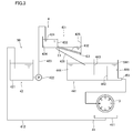
- FIG. 3 is a schematic view of an antifoaming device included in the quenching device of the present embodiment.
- 4 is a plan view of the defoaming tank included in the defoaming apparatus shown in FIG.
- FIG. 5 is a front view of the supply member in FIG. 4.
- the quenching apparatus performs quenching by injecting a coolant onto the metal material.
- the quenching device includes a defoaming device, a supply tank, and a cooling device.
- the defoamer removes bubbles from the coolant.
- the supply tank stores the coolant from which bubbles have been removed.
- the cooling device injects the coolant supplied from the supply tank toward the metal material.
- the defoaming device includes a defoaming tank and a circulation device.
- the circulation device collects the cooling liquid after quenching and supplies it to the defoaming tank.
- the defoaming tank includes a laminar flow weir.
- the laminar weir partitions the defoaming tank into a laminar tank and a shallow tank and is lower than the side wall of the laminar tank.
- the laminar flow tank is supplied with a cooling liquid from a circulation device, and the shallow water tank is poured with a cooling liquid over the laminar flow weir by overflow from the laminar flow tank.
- the shallow tank includes a bottom having an opening and a filter.
- the filter is plate-shaped or sheet-shaped and has a mesh structure. The filter covers the bottom opening.
- the liquid level of the shallow tank is less than that of the laminar weir.
- the supply tank stores the coolant that has passed through the filter.
- the quenching apparatus In a quenching apparatus that quenches by injecting coolant, if the amount of bubbles in the coolant is large, the cooling capacity of the coolant decreases. Specifically, the heat transfer efficiency of gas is lower than the heat transfer efficiency of liquid. Therefore, if the bubble content of the cooling liquid is high, the influence of the bubbles on the cooling capacity increases, and the cooling capacity decreases.
- the quenching apparatus according to the present embodiment bubbles are removed from the coolant before being used for quenching. Therefore, the quenching apparatus of this embodiment can increase the cooling capacity of the coolant and can sufficiently quench the metal material. Therefore, hardenability is stabilized.
- quenching apparatus of this embodiment When the quenching apparatus of this embodiment is used in a 3DQ apparatus, quenching of a metal material portion bent by the 3DQ apparatus can be obtained substantially uniformly and stably. Therefore, the accuracy of the processing shape of the metal material processed by the 3DQ apparatus is stabilized.
- air bubbles contained in the coolant recovered after quenching are further reduced by the following method.
- the coolant In a quenching apparatus that quenches by injecting a coolant, the coolant is allowed to collide with the metal material so as to increase the cooling heat transfer area in order to quench the metal material efficiently. In this case, the flow of the coolant is disturbed by the collision. Furthermore, since the coolant is scattered in the atmosphere, bubbles are included in the coolant at this time. Therefore, many bubbles are contained in the coolant after quenching.
- the cooling liquid containing many bubbles after quenching is collected in a circulation device and supplied to the laminar flow tank in the defoaming tank.
- the flow of the cooling liquid supplied to the laminar flow tank is in a turbulent state. Therefore, many bubbles are contained in the coolant supplied to the laminar flow tank.
- the coolant is temporarily stored. Bubbles contained in the stored cooling liquid naturally float upward and disappear at the liquid level. The coolant in which the bubbles are reduced to some extent overflows the laminar flow weir lower than the side wall of the laminar flow tank, and is poured into the shallow tank over the laminar flow weir.
- the coolant flowing down over the laminar flow weir is in a laminar flow state because the flow rate is slow and flows in one direction. Therefore, the collision between the cooling liquid flowing down the laminar flow weir and the bottom of the shallow water tank or the liquid level of the cooling liquid stored in the shallow water tank is alleviated, and a vortex is generated at the time of the collision and new bubbles are included. Suppress. As described above, in the laminar flow tank, bubbles are removed to some extent from the coolant recovered after quenching and the coolant is brought into a laminar flow state in order to suppress new entrainment of bubbles.
- the shallow tank where the coolant is poured from the laminar flow tank, the bubbles in the coolant are removed in a shorter time.
- the shallow tank has a mesh structure filter at the bottom, and the poured coolant is supplied to the supply tank through the filter.
- the following two functions are exhibited by arranging the filter at the bottom. 1stly, it suppresses that the cooling fluid containing a bubble is supplied to a supply tank by a filter, and a filter accelerates
- the level of the liquid level in the shallow water tank is kept lower than the height of the laminar flow weir by the filter.
- the liquid level height of the shallow water tank is lower than the liquid level height of the cooling liquid in the laminar flow tank.
- the lower the liquid level the shorter the time for the bubbles in the coolant to naturally float on the liquid level. Therefore, the shallow water tank can remove bubbles from the coolant in a short time.
- the quenching apparatus of this embodiment reduces the amount of bubbles in the coolant that circulates in a large amount in a short time and reuses it for quenching. Therefore, the cooling capacity of the coolant can be increased.
- the filter is, for example, a nonwoven fabric, a perforated plate (metal plate, non-metal plate), a wire mesh, or the like.
- the part covered by the filter in the bottom of the shallow water tank is inclined downward as the distance from the laminar tank is increased.
- the flow of the coolant in the shallow water tank can be unidirectional due to the inclination. Thereby, it can suppress that the flow of a cooling fluid is disturb
- the following effects can be obtained by tilting.
- a coolant with less bubbles passes through the filter.
- the cooling liquid with many bubbles cannot pass through the upstream portion of the filter. Therefore, it flows to the downstream part of the filter along the inclination.
- a coolant with a lot of bubbles accumulates below the shallow water tank.
- the laminar coolant can have a wide contact area (area through which the coolant passes) with respect to the filter.
- the coolant over the laminar flow weir intensively collides with the filter near the laminar flow weir. Even if the coolant contains bubbles, if it enters the filter in the vertical direction, there is a high possibility that the coolant containing bubbles will pass through the filter.
- the vertical component of the coolant speed is reduced as compared with the case where the shallow tank is not inclined. In this case, if the flow path resistance is the same, the cooling liquid containing bubbles is less likely to pass through the filter when the bottom of the shallow tank is tilted than when the bottom is not tilted. Furthermore, since the passage area of the coolant can be increased with respect to the filter, bubbles in the coolant can be more efficiently removed.
- the quenching apparatus further includes a conveying member.
- the conveying member is disposed below the filter and has an inclined channel. The conveying member pours the coolant that has passed through the filter into the supply tank.
- the supply tank includes a side wall and a first flow path weir.
- the side wall has an outlet at the bottom.
- the first flow path weir is disposed closer to the side wall than just below the filter in the supply tank.
- the first channel weir has an opening at the bottom. The coolant supplied to the supply tank through the filter reaches the discharge port through the opening of the first flow path weir.
- the coolant does not reach the discharge port unless it passes through the opening formed in the lower portion of the first flow path weir. Therefore, when passing through the first flow path weir, the coolant flows through the lower part in the supply tank. At this time, since the bubbles in the coolant rise upward, the bubbles are easily removed from the coolant that has passed through the opening.
- the supply tank further includes a second flow path weir.
- the second flow path weir is disposed between the first flow path weir and the side wall having the discharge port, and is lower than the side wall.
- the coolant that has passed through the filter and is supplied into the supply tank passes through the opening of the first flow path weir and then passes through the second flow path weir to reach the discharge port.
- the flow path of the coolant in the supply tank can be further lengthened by the first and second flow path weirs. Furthermore, the number of times the coolant moves in the vertical direction in the coolant flow path also increases. Therefore, the bubbles are more likely to rise.
- the circulation device includes a main pipe through which the coolant passes and a plurality of branch pipes branched from the main pipe and each having a supply port.
- the coolant is poured from the branch pipe into the laminar flow tank.
- the total cross-sectional area of each branch pipe is larger than the cross-sectional area of the main pipe.
- the coolant in the main pipe is branched.
- the total cross-sectional area of each branch pipe (cross-section perpendicular to the central axis of the branch pipe) is larger than the cross-sectional area of the main pipe (cross-section perpendicular to the central axis of the main pipe), so that it is supplied to the laminar flow tank.
- the flow rate of the coolant at that time becomes small. Therefore, the collision with the already stored coolant is eased. As a result, generation of bubbles in the coolant can be suppressed.
- the circulation device further includes a storage tank.
- the storage tank stores the coolant recovered after quenching.
- the circulation device supplies the coolant in the storage tank to the defoaming tank.
- the coolant is stored in the storage tank before being supplied to the defoaming tank.
- the storage tank not only bubbles contained in the cooling liquid after quenching but also scales and the like naturally float and are removed. Therefore, before the cooling liquid is supplied to the defoaming tank, bubbles and scales contained in the cooling liquid can be removed to some extent.
- the metal material manufacturing method of the present embodiment uses the above-described quenching apparatus.
- the manufacturing apparatus includes a step of heating a metal material and a step of performing quenching on the metal material by injecting a cooling liquid onto the heated metal material.
- the step of performing the quenching includes a step of removing bubbles from the coolant by the defoaming device, and a step of spraying the coolant from which the bubbles are removed to the heated metal material.
- the metal material manufacturing method In the metal material manufacturing method according to this embodiment, bubbles are removed from the coolant before being used for quenching. Therefore, the cooling capacity of the cooling liquid is increased, and the metal material is sufficiently quenched. As a result, variation in quenching of the metal material can be reduced.
- the manufacturing method of the metal material of this embodiment is implemented using a 3DQ apparatus, quenching of the metal material part bent by the 3DQ apparatus can be obtained substantially uniformly and stably. Therefore, the accuracy of the processing shape of the metal material processed by 3DQ is stabilized.
- FIG. 1 is a perspective view of the 3DQ device 100.
- the 3DQ device 100 includes a feeding device 110, a support device 120, a quenching device 1, and a gripping device 130.
- the feeding device 110 transports the metal material 10 in the axial direction X of the metal material 10 at a predetermined feed speed.
- the metal material 10 is, for example, a metal pipe, for example, a steel pipe.
- the feeding device 110 includes a gripping member 111 and a conveying device 112.
- the gripping member 111 is connected to the transport device 112.
- the gripping member 111 grips the metal material 10 so as to be rotatable around the central axis of the metal material 10.
- the conveying device 112 moves the metal material 10 in the axial direction X together with the gripping member 111.
- the transport device 112 is, for example, an electric servo cylinder, a mechanism using a ball screw, or the like.
- the support device 120 is arranged on the downstream side (X direction) from the feeding device 110.
- the support device 120 supports the metal material 10 conveyed in the axial direction (X direction).
- the support device 120 includes a pair of roll groups 121, for example.
- the pair of roll groups 121 sandwich the metal material 10 and support the metal material 10 so as to be movable in the axial direction X.
- the support device 120 may have another configuration in place of the pair of roll groups 121.
- the quenching device 1 is disposed on the downstream side of the support device 120.
- the quenching device 1 includes a heating device 2 and a cooling device 3.
- the cooling device 3 is disposed on the downstream side of the heating device 2.
- the quenching apparatus 1 heats a part of the conveyed metal material 10. A bending moment is given to the heated portion of the metal material 10 by the gripping device 130. That is, in the 3DQ apparatus, the bending process is performed on the heated portion of the metal material 10 while moving the metal material 10 in the X direction. The heated part that has been bent and deformed is quenched by the cooling device 3.
- the gripping device 130 moves and rotates while gripping the metal material 10. Thereby, the gripping device 130 gives a bending moment to the heated portion of the metal material 10.
- the gripping device 130 is, for example, a pair of movable roller dies shown in FIG.
- the gripping device 130 may be a multi-axis robot arm instead of the movable roller die.
- FIG. 2 is a cross-sectional view of the quenching apparatus 1 in FIG. As described above, the quenching device 1 includes the heating device 2 and the cooling device 3.
- the heating device 2 is annular or cylindrical.
- the heating device 2 passes the metal material 10 inside. That is, the heating device 2 is disposed around the metal material 10 during bending.
- the heating device 2 is, for example, a high frequency heating coil.
- the cooling device 3 is annular or cylindrical.
- the cooling device 3 has a plurality of injection ports 31 on the inner peripheral surface.
- the plurality of injection ports 31 inject cooling liquid toward the center (central axis X) of the cooling device 3.
- the plurality of injection ports 31 may face the downstream side. In this case, the injection port 31 injects the coolant toward the central axis X on the downstream side.
- the cooling device 3 may include a plurality of injection nozzles. In this case, the plurality of injection ports 31 correspond to injection nozzle ports.
- the cooling liquid is, for example, water, antifreeze liquid or the like.
- the quenching apparatus 1 further includes a defoaming apparatus 4 shown in FIG. 3 and a supply tank 441.
- the defoaming device 4 removes bubbles from the coolant before being supplied to the cooling device 3.
- the supply tank 441 stores the coolant from which bubbles have been removed by the defoaming device 4.
- the cooling device 3 cools the coolant supplied from the supply tank 441 by spraying the coolant toward the metal material.
- the cooling capacity of the coolant at the time of jetting will decrease. This is because bubbles have a lower cooling capacity than the coolant. If there are many air bubbles contained in the cooling liquid, the cooling capacity further decreases. For this reason, when quenching is performed by injecting a coolant, quenching is difficult to obtain stably. Unless quenching is obtained uniformly and stably in the 3DQ apparatus 100, it is difficult to stably obtain the accuracy of the processed shape of the bent metal material 10.
- the quenching apparatus 1 of this embodiment bubbles are removed from the coolant before the defoaming apparatus 4 is used for quenching. Therefore, the cooling capacity at the time of quenching is increased and stabilized. As a result, the hardenability is improved and the quenching effect is stably obtained. In this case, in the 3DQ apparatus 100, the accuracy of the processed shape of the bent metal material 10 is stably obtained.
- the defoaming apparatus 4 will be described.
- the defoaming device 4 includes a circulation device 50 and a defoaming tank 431.
- the coolant sprayed from the cooling device 3 during quenching collides with the metal material 10, the coolants, or the components of the device. Due to this collision, the cooling liquid contains a large amount of bubbles.
- the defoaming tank 431 in the defoaming device 4 removes bubbles in the coolant.
- the storage mechanism 42 in the circulation device 50 reduces the amount of bubbles in the coolant supplied to the defoaming tank 431.
- the supply tank 441 further reduces the amount of bubbles in the coolant from which bubbles have been removed in the defoaming tank 431.
- the circulation device 50 collects the cooling liquid after quenching and supplies it to the defoaming tank 431.
- the circulation device 50 includes a recovery mechanism 41 and a storage mechanism 42.
- the cooling liquid used for quenching is circulated and used.
- the recovery mechanism 41 recovers the coolant used for quenching.
- the recovery mechanism 41 further supplies the recovered cooling liquid to the storage mechanism 42.
- the recovery mechanism 41 includes a collection tank 411 and a pipe 412.
- the collection tank 411 is disposed below the cooling device 3 and collects the used coolant.
- the collected coolant is supplied to the storage mechanism 42 via the pipe 412.
- a pump (not shown) is used for the supply.
- the recovery mechanism 41 may have a configuration other than the configuration shown in FIG.
- the storage mechanism 42 stores the coolant supplied from the recovery mechanism 41.
- the storage mechanism 42 includes a storage tank 421, a pump 422, and a supply member 423.
- the storage tank 421 stores the coolant recovered by the recovery mechanism 41.
- the storage tank 421 can reduce the amount of bubbles in the coolant.
- the storage tank 421 not only the bubbles of the cooling liquid but also the scale and the like contained in the cooling liquid after quenching use naturally float. Therefore, the coolant from which scales and the like have been removed can be supplied to the defoaming tank 431.
- the supply member 423 is a pipe having a supply port on the downstream side.
- the coolant flowing out from the supply port is supplied to the defoaming tank 431.
- the pump 422 supplies the coolant once stored in the storage tank 421 to the defoaming tank 431 via the supply member 423.
- the defoaming tank 431 removes bubbles from the coolant using a filter.
- the defoaming tank 431 includes a laminar flow weir 433.
- the laminar flow weir 433 partitions the defoaming tank 431 into a laminar flow tank 434 and a shallow water tank 435.
- a supply port of the supply member 423 is disposed in the laminar flow tank 434. Therefore, the coolant conveyed from the storage tank 421 is supplied to the laminar flow tank 434.
- the laminar flow tank 434 temporarily stores the coolant. Bubbles in the cooling liquid naturally float during the storage period and disappear at the liquid level. Therefore, the laminar flow tank 434 reduces the amount of bubbles in the coolant.
- the supply port of the supply member 423 is disposed in the laminar flow tank 434 and at a position lower than the upper end of the laminar flow weir 433.
- the supply port is disposed below the liquid level of the laminar flow tank 434. Therefore, the cooling liquid exiting the supply port is poured into the cooling liquid stored in the laminar flow tank 434 without contacting air. Therefore, it is difficult for bubbles to enter.
- the shallow tank 435 includes a bottom having an opening and a filter 432.
- a filter 432 is disposed in the opening at the bottom.
- the filter 432 is plate-shaped or sheet-shaped and has a mesh structure. More specifically, the filter 432 has a plurality of holes (through holes). Preferably, the plurality of holes have a size that prevents bubbles in the coolant from passing through.
- the cooling liquid at the bottom in the shallow tank 435 is supplied to the supply tank 441 because air bubbles are removed and the filter 432 can pass through.
- the filter 432 is not particularly limited as long as it has a hole capable of suppressing the passage of bubbles.
- the filter 432 is, for example, a nonwoven fabric, a wire mesh, or a perforated plate.
- the perforated plate may be a metal plate or a non-metallic plate.
- the height of the laminar flow weir 433 is lower than the height of the side wall of the laminar flow tank 434. Therefore, when the height of the coolant stored in the laminar flow tank 434 exceeds the laminar flow weir 433, the coolant overflows from the laminar flow tank 434 and flows out to the shallow water tank 435. At this time, the coolant travels through the laminar flow weir 433 and reaches the filter 432 by natural flow.
- the laminar flow tank 434 In the first bubble removal step, bubbles in the cooling liquid supplied from the circulation device 50 are removed in the laminar flow tank 434, and the flow of the cooling liquid is further adjusted (laminarization). Specifically, the recovered cooling liquid is supplied to the laminar flow tank 434 by the circulation device 50.
- the coolant supplied by the circulation device 50 is in a turbulent state and includes many bubbles.
- a time for temporarily storing the coolant can be given. As a result, bubbles contained in the stored coolant naturally float upward and disappear at the liquid level. Therefore, the laminar flow tank 434 removes bubbles in the coolant to some extent.
- the laminar flow weir 433 is lower than the side wall of the laminar flow tank 434. Therefore, the cooling liquid in which bubbles are reduced to some extent passes over the upper end of the laminar flow weir 433 lower than the side wall of the laminar flow tank 434, overflows the laminar flow weir 433, and is poured into the shallow water tank 435. At this time, the coolant flowing down through the laminar flow weir 433 decreases the flow velocity, flows in one direction, and is in a laminar flow state.
- the laminar flow weir 433 is wider. In this case, the coolant flowing down the laminar flow weir 433 is more likely to be in a laminar flow state.
- the laminar flow tank 434 removes bubbles to some extent from the coolant recovered after quenching. Furthermore, since the coolant in the turbulent state is poured into the shallow tank 435 in a laminar flow state, the collision between the coolant when the coolant is poured into the shallow tank 435 and the coolant accumulated in the shallow tank 435 is reduced. Suppresses bubbles from entering the coolant due to the collision.
- the shallow tank 435 has a mesh structure (porous) filter 432 at the bottom.
- the filter 432 prevents the coolant containing bubbles from being supplied to the supply tank 441, and the filter 432 promotes the removal of the bubbles in the coolant.
- the liquid level is maintained lower than that of the laminar flow weir 433 by the filter 432. Therefore, the liquid level height of the shallow tank 435 is lower than that of the laminar flow tank 434. The lower the liquid level, the shorter the time for bubbles in the coolant to rise to the surface. Therefore, the shallow water tank can further remove bubbles from the laminar coolant in a short time.
- the liquid surface height of the shallow water tank 435 is not particularly limited as long as it is lower than the height of the laminar flow weir 433, but is preferably 30 cm or less, and more preferably 20 cm or less. If the liquid level height of the shallow tank 435 is within the above-described preferable range, the time until the bubbles in the coolant accumulated in the shallow tank 435 naturally float and reach the water surface is short. Therefore, bubbles can be removed more effectively.
- the area of the filter 432 of the shallow tank 435 is preferably large. The larger the area of the filter 432, the lower the liquid level of the shallow tank 435.
- the portion of the bottom of the shallow water tank 435 covered by the filter 432 is inclined downward as the distance from the laminar flow tank 434 increases.
- the portion covered by the filter 432 in the bottom portion of the shallow water tank 435 is arranged such that the edge E2 opposite to the edge E1 is disposed below the edge E1 on the laminar flow tank 434 side.
- the coolant that has flowed down through the laminar flow weir 433 tends to flow in one direction from the edge E1 toward the edge E2. If the direction in which the coolant flows is not constant, the coolant flow may be disturbed and vortices may be generated. In this case, bubbles easily enter the coolant. Since the bottom of the shallow tank 435 of the present embodiment is inclined, the flow of the coolant is hardly disturbed. Therefore, it is difficult for bubbles to enter the coolant.
- the following effects can be obtained by the inclination.
- the coolant with less bubbles passes through the filter 432.
- the coolant with many bubbles cannot pass through the upstream portion of the filter 432. Therefore, the cooling liquid containing a large amount of bubbles flows to the downstream portion of the filter 432 along the inclination.
- a coolant with a lot of bubbles accumulates below the shallow tank 435.
- the liquid level of the shallow tank 435 is low, bubbles in the cooling liquid naturally float and disappear below the shallow tank 435. In this manner, a laminar flow of the cooling liquid along the inclination can obtain a wide contact area (area through which the cooling liquid passes) with respect to the filter 432.
- the coolant that has passed through the laminar flow weir 433 collides with the filter near the laminar flow weir 433 in a concentrated manner. Even if the coolant contains bubbles, if the coolant enters the filter in the vertical direction, there is a high possibility that the coolant containing bubbles will pass through the filter 432.
- the bottom portion of the shallow tank 435 is inclined as described above, the vertical component of the coolant speed is smaller than when the bottom portion is not inclined. In this case, if the flow path resistance is the same, the cooling liquid containing bubbles is less likely to pass through the filter 432 when the bottom of the shallow tank 435 is inclined than when the bottom is not inclined. . Furthermore, since the passage area of the coolant can be increased with respect to the filter 432, bubbles in the coolant can be more efficiently removed.
- the part with less bubbles in the cooling liquid can pass through the filter 432 at an early stage, and the cooling liquid with many bubbles uses natural levitation below the shallow water tank 435. Remove bubbles. Therefore, a large amount of cooling liquid with few bubbles can be efficiently supplied to the supply tank 441 in a short time.
- the defoaming device 4 further includes a conveying member 436.
- the conveying member 436 is disposed below the filter 432.
- the upper surface of the conveying member 436 has an inclined channel. Specifically, the flow path inclines downward as it moves away from the laminar flow tank 434.
- the conveying member 436 may be a member in which a groove (flow path) is formed, for example. Further, the conveying member 436 may have a plate shape in which a side wall is formed.
- the inclination angle of the flow path may be different from or the same as the inclination angle of the filter 432.
- the coolant that has passed through the filter 432 flows down the supply tank 441 through the flow path of the transport member 436. At this time, the direction in which the coolant flows is likely to be constant, and vortices are less likely to occur during the flow. Therefore, it is difficult for bubbles to enter the coolant.
- the supply tank 441 supplies the cooling liquid from which bubbles have been removed by the defoaming tank 431 to the cooling device 3. At this time, the supply tank 441 supplies the cooling liquid to the cooling device 3 while suppressing bubbles from entering the cooling liquid supplied from the defoaming tank 431.
- the supply tank 441 includes a side wall SW1 having a discharge port EX at the bottom.
- the supply tank 441 further includes flow path weirs 442 and 443.
- the supply tank 441 is disposed below the defoaming tank 431.
- the lower end of the flow path of the conveying member 436 is disposed in the supply tank 441 and below the upper end of the side wall of the supply tank 441.
- the lower end of the flow path of the conveying member 436 is disposed in the vicinity of the liquid level in the supply tank 441 or below the liquid level. Therefore, it is possible to reduce the collision between the cooling liquid flowing down through the flow path and the liquid level, and to suppress the generation of bubbles.
- the supply tank 441 is divided into a tank 444 and a tank 445 by a flow path weir 442.
- the channel weir 442 is disposed on the side wall SW ⁇ b> 1 rather than directly below the filter 432.
- the channel weir 442 is disposed between the lower end of the channel of the transport member 436 and the discharge port EX.
- the channel weir 442 is disposed between the channel weir 443 and the side wall SW1.
- the channel weir 442 is arranged upright on the bottom of the supply tank 441.
- the discharge port EX is formed below the side wall SW1 of the tank 445.
- the flow path weir 442 is lower than the side wall of the supply tank 441. Therefore, the coolant that has passed through the filter 432, more preferably, the coolant that has flowed from the flow path of the conveying member 436 to the supply tank 441 passes through the flow path weir 442 and reaches the discharge port EX.
- the flow path weir 443 is disposed in the supply tank 441 closer to the side wall SW1 than just below the filter 432.
- the channel weir 443 is disposed between the lower end of the channel of the conveying member 436 and the channel weir 442. That is, the channel weir 443 further divides the tank 444 into two tanks.
- the channel weir 443 has an opening at the bottom. A part of the lower part of the flow path weir 443 may be opened, or the whole lower part may be opened.
- the upper end of the channel weir 443 is disposed at a position higher than the upper end of the side wall of the supply tank 441.
- the flow path weirs 442 and 443 form a flow path for the coolant in the supply tank 441. Specifically, the coolant that has flowed from the flow path of the transport member 436 to the supply tank 441 flows downward by the flow path weir 443. The coolant passes through the opening at the bottom of the flow path weir 443. Thereafter, the coolant rises by the flow path weir 442. After the coolant passes over the flow path weir 442, it flows downward again and reaches the discharge port EX.
- the coolant repeatedly rises and falls in the supply tank 441 and reaches the discharge port EX. Therefore, the supply tank 441 forms a long flow path as compared with the case where the flow path weir 442 and the flow path weir 443 are not provided. If the passage flow path is long, it is possible to give time for the bubbles to naturally float. For this reason, bubbles in the coolant are likely to rise and be easily removed. Further, the flow path includes a flow in the vertical direction due to the flow path weir 442 and the flow path weir 443. The vertical flow helps the bubble to rise. As a result, bubbles in the coolant are easily removed.
- the coolant that has exited from the discharge port EX is supplied to the cooling device 3 by a pump (not shown). And a cooling fluid is injected from the injection port of the cooling device 3, and quenches a metal material.
- the metal material is quenched using the quenching apparatus 1 in the 3DQ apparatus 100.
- the metal material 10 is heated by the heating device 2.
- the heated metal material 10 is subjected to a bending process by applying a bending moment using the gripping device 130.
- the bent metal material 10 is quenched by injecting a coolant from the cooling device 3 (quenching process).
- the quenching process includes a bubble removing process and a cooling process.
- the defoaming device 4 is used to remove bubbles in the coolant after being used for quenching.
- the cooling process the metal material 10 is cooled by ejecting the cooling liquid from which the bubbles are removed and the amount of bubbles is reduced from the cooling device 3. As a result, a substantially uniform quenching can be stably obtained. If quenching can be obtained uniformly and stably in the 3DQ apparatus 100, the accuracy of the processed shape of the bent metal material 10 can also be stably obtained. Through the above steps, a quenched metal material can be manufactured.
- FIG. 4 is a plan view of the supply member 423 and its peripheral portion of the quenching apparatus 1 according to the second embodiment.
- FIG. 5 is a front view of the supply member 423.
- the supply member 423 includes a main pipe 426 and a plurality of branch pipes 425.
- the plurality of branch pipes 425 branch from the main pipe 426.
- the end of each branch pipe 425 is open and constitutes a supply port.
- the total cross-sectional area of each branch pipe 425 (area of a cross section perpendicular to the central axis of the branch pipe 425) is larger than the cross-sectional area of main pipe 426 (area of a cross section perpendicular to the central axis of the main pipe 426).
- the coolant conveyed through the main pipe 426 branches into a plurality of branch pipes 425.
- the total cross-sectional area of each branch pipe 425 is larger than the cross-sectional area of the main pipe 426. Therefore, the flow rate of the coolant in each branch pipe 425 is smaller than the flow rate of the coolant flowing through the main pipe 426. As a result, the flow rate of the coolant near the supply port becomes slower than the flow rate of the coolant in the main pipe 426. If the flow rate is slowed, the collision between the coolant discharged from the branch pipe 425 and the liquid level in the laminar flow tank 434 is eased. Therefore, generation
- the total sectional area of the inner diameters of the plurality of branch pipes 425 is larger than the sectional area of the inner diameter of the main pipe 426.
- the flow rate of the cooling liquid in the branch pipe 425 is smaller than the flow rate in the main pipe 426.
- the quenching apparatus includes the defoaming device 4 including the circulation device 50 and the defoaming tank 431 and the supply tank 441.
- the quenching apparatus may include at least the defoaming tank 431 and the supply tank 441.
- the coolant sprayed from the cooling device 3 is directly supplied to the defoaming tank 431.
- the coolant from which bubbles are removed in the defoaming tank 431 is supplied to the cooling device 3 via the supply tank 441.
- a part of the bottom of the shallow tank 435 may not be inclined, and the bottom covered by the filter 432 may not be inclined. Even in this case, the filter 432 can remove bubbles of the coolant.
- the conveying member 436 may not be arranged. In this case, the coolant that has passed through the filter 432 naturally falls into the supply tank 441 disposed below. The bubbles of the cooling liquid are removed by the filter 432. Therefore, even if the conveying member 436 is not disposed, the effect of removing bubbles by the filter 432 is maintained to some extent.
- the flow path weir 442 and / or 443 of the supply tank 441 may not be arranged. Even in this case, similarly to the storage tank 421, the supply tank 441 temporarily stores the coolant. Therefore, the bubbles in the cooling liquid are likely to rise, and the bubbles are removed to some extent.
- the flow path dam 443 may be disposed in the supply tank 441 and the flow path dam 442 may not be disposed. When the coolant passes through the opening in the lower part of the flow path weir 443, the coolant flows in the lower part in the supply tank 441. At this time, the bubbles in the coolant rise and the bubbles in the coolant are easily removed.
- the supply member 423 in the circulation device 50 is a pipe.
- the supply member 423 may have a configuration other than piping.
- the supply member 423 may have the same configuration as the transport member 436.
- each of the support device 120 and the gripping device 130 includes a pair or a plurality of pairs of rollers.
- the support device 120 and / or the gripping device 130 may be a multi-axis robot arm.
- the quenching apparatus 1 is applied to the 3DQ apparatus 100.
- the above-described quenching apparatus 1 may be used for apparatuses other than the 3DQ apparatus 100, or may be used by the quenching apparatus 1 alone.
Landscapes
- Chemical & Material Sciences (AREA)
- Engineering & Computer Science (AREA)
- Materials Engineering (AREA)
- Thermal Sciences (AREA)
- Crystallography & Structural Chemistry (AREA)
- Mechanical Engineering (AREA)
- Physics & Mathematics (AREA)
- Metallurgy (AREA)
- Organic Chemistry (AREA)
- Chemical Kinetics & Catalysis (AREA)
- Dispersion Chemistry (AREA)
- Heat Treatments In General, Especially Conveying And Cooling (AREA)
- Heat Treatment Of Strip Materials And Filament Materials (AREA)
Priority Applications (5)
| Application Number | Priority Date | Filing Date | Title |
|---|---|---|---|
| KR1020177000054A KR101871124B1 (ko) | 2014-06-05 | 2015-06-01 | 담금질 장치 및 금속재의 제조 방법 |
| JP2016525692A JP6009129B2 (ja) | 2014-06-05 | 2015-06-01 | 焼入れ装置及び金属材の製造方法 |
| US15/314,956 US10329634B2 (en) | 2014-06-05 | 2015-06-01 | Quenching apparatus and method for producing metallic material |
| EP15803190.6A EP3153596B1 (de) | 2014-06-05 | 2015-06-01 | Abschreckvorrichtung und verfahren zur herstellung eines metallischen materials |
| CN201580029998.0A CN106460082B (zh) | 2014-06-05 | 2015-06-01 | 淬火装置以及金属件的制造方法 |
Applications Claiming Priority (2)
| Application Number | Priority Date | Filing Date | Title |
|---|---|---|---|
| JP2014116965 | 2014-06-05 | ||
| JP2014-116965 | 2014-06-05 |
Publications (1)
| Publication Number | Publication Date |
|---|---|
| WO2015186337A1 true WO2015186337A1 (ja) | 2015-12-10 |
Family
ID=54766421
Family Applications (1)
| Application Number | Title | Priority Date | Filing Date |
|---|---|---|---|
| PCT/JP2015/002750 WO2015186337A1 (ja) | 2014-06-05 | 2015-06-01 | 焼入れ装置及び金属材の製造方法 |
Country Status (6)
| Country | Link |
|---|---|
| US (1) | US10329634B2 (de) |
| EP (1) | EP3153596B1 (de) |
| JP (1) | JP6009129B2 (de) |
| KR (1) | KR101871124B1 (de) |
| CN (1) | CN106460082B (de) |
| WO (1) | WO2015186337A1 (de) |
Families Citing this family (4)
| Publication number | Priority date | Publication date | Assignee | Title |
|---|---|---|---|---|
| WO2015186337A1 (ja) * | 2014-06-05 | 2015-12-10 | 新日鐵住金株式会社 | 焼入れ装置及び金属材の製造方法 |
| CN108591185A (zh) * | 2018-03-29 | 2018-09-28 | 新兴能源装备股份有限公司 | 一种cng液压子站液压油减少气泡装置 |
| CN109175037B (zh) * | 2018-08-28 | 2020-04-07 | 南京航威智造科技有限公司 | 一种基于双臂机器人的三维复杂构件扭曲成形系统及方法 |
| CN110666141B (zh) * | 2019-10-24 | 2021-08-24 | 金堆城钼业股份有限公司 | 一种钼铁锭淬冷装置及其淬冷方法 |
Citations (4)
| Publication number | Priority date | Publication date | Assignee | Title |
|---|---|---|---|---|
| JPS5628611A (en) * | 1979-08-16 | 1981-03-20 | Ishikawajima Harima Heavy Ind Co Ltd | Bubble removing device |
| JPH07265613A (ja) * | 1994-04-01 | 1995-10-17 | Fuji Denshi Kogyo Kk | 焼入液用フィルター |
| JP3056283U (ja) * | 1998-07-29 | 1999-02-12 | 株式会社シイエヌケイ | 浮上泡の捕集排出機構を設けたクーラントタンク |
| JP3058161U (ja) * | 1998-09-30 | 1999-06-08 | 株式会社シイエヌケイ | 浮上泡を含有するクーラントの処理用タンク装置 |
Family Cites Families (11)
| Publication number | Priority date | Publication date | Assignee | Title |
|---|---|---|---|---|
| US2893409A (en) * | 1955-06-25 | 1959-07-07 | Deutsche Edelstahlwerke Ag | Apparatus and method for cooling or quenching |
| JPS5173911A (en) * | 1974-12-24 | 1976-06-26 | Nippon Kokan Kk | Kosutoritsupuoteisankajotaidemizuyakiiresuruhoho oyobi sochi |
| JPH0356283U (de) * | 1989-10-06 | 1991-05-30 | ||
| JPH0443093Y2 (de) * | 1989-10-09 | 1992-10-12 | ||
| JP3056283B2 (ja) * | 1991-04-30 | 2000-06-26 | 三菱化学株式会社 | クーロメータ型電解セル用作用電極 |
| JP3058161B1 (ja) * | 1999-02-26 | 2000-07-04 | 株式会社移動体通信先端技術研究所 | 共振器の共振周波数調整方法およびその方法を用いて周波数調整された共振器 |
| EP1857195B8 (de) | 2005-03-03 | 2014-07-30 | Nippon Steel & Sumitomo Metal Corporation | Verfahren zum Biegen von Metallmaterial und gebogenes Produkt |
| CN2856059Y (zh) * | 2006-01-10 | 2007-01-10 | 吐哈石油勘探开发指挥部机械厂 | 细长管金属材料中频淬火两级防变形喷水线圈 |
| JP4596478B2 (ja) * | 2006-02-28 | 2010-12-08 | 高周波熱錬株式会社 | 消泡装置 |
| CN202116602U (zh) * | 2011-06-07 | 2012-01-18 | 襄阳丰正汽车配件制造有限公司 | 余热淬火冷却装置 |
| WO2015186337A1 (ja) * | 2014-06-05 | 2015-12-10 | 新日鐵住金株式会社 | 焼入れ装置及び金属材の製造方法 |
-
2015
- 2015-06-01 WO PCT/JP2015/002750 patent/WO2015186337A1/ja active Application Filing
- 2015-06-01 JP JP2016525692A patent/JP6009129B2/ja active Active
- 2015-06-01 EP EP15803190.6A patent/EP3153596B1/de active Active
- 2015-06-01 KR KR1020177000054A patent/KR101871124B1/ko active IP Right Grant
- 2015-06-01 US US15/314,956 patent/US10329634B2/en active Active
- 2015-06-01 CN CN201580029998.0A patent/CN106460082B/zh active Active
Patent Citations (4)
| Publication number | Priority date | Publication date | Assignee | Title |
|---|---|---|---|---|
| JPS5628611A (en) * | 1979-08-16 | 1981-03-20 | Ishikawajima Harima Heavy Ind Co Ltd | Bubble removing device |
| JPH07265613A (ja) * | 1994-04-01 | 1995-10-17 | Fuji Denshi Kogyo Kk | 焼入液用フィルター |
| JP3056283U (ja) * | 1998-07-29 | 1999-02-12 | 株式会社シイエヌケイ | 浮上泡の捕集排出機構を設けたクーラントタンク |
| JP3058161U (ja) * | 1998-09-30 | 1999-06-08 | 株式会社シイエヌケイ | 浮上泡を含有するクーラントの処理用タンク装置 |
Also Published As
| Publication number | Publication date |
|---|---|
| EP3153596A1 (de) | 2017-04-12 |
| CN106460082A (zh) | 2017-02-22 |
| KR20170013382A (ko) | 2017-02-06 |
| US10329634B2 (en) | 2019-06-25 |
| JP6009129B2 (ja) | 2016-10-19 |
| CN106460082B (zh) | 2018-07-03 |
| JPWO2015186337A1 (ja) | 2017-04-20 |
| US20170198367A1 (en) | 2017-07-13 |
| EP3153596A4 (de) | 2017-11-15 |
| KR101871124B1 (ko) | 2018-06-25 |
| EP3153596B1 (de) | 2018-09-12 |
Similar Documents
| Publication | Publication Date | Title |
|---|---|---|
| JP6009129B2 (ja) | 焼入れ装置及び金属材の製造方法 | |
| KR102023328B1 (ko) | 표면 처리 장치 | |
| CN107922984B (zh) | 用于热的非无尽表面的均匀非接触式冷却的方法及其装置 | |
| KR101659474B1 (ko) | 주조 설비, 압연 설비 또는 기타 스트립 처리 라인에서 표면을 냉각하기 위한 방법 및 그 장치 | |
| CN104324587A (zh) | 细孔筛板式鼓泡塔 | |
| CN105359259A (zh) | 线性马兰哥尼干燥器中的单次使用的冲洗 | |
| JP2013139037A (ja) | 連続フローピンウォッシャ | |
| EP3205419A1 (de) | Kühlvorrichtung und kühlverfahren für stahlmaterial | |
| KR102141068B1 (ko) | 열처리로 | |
| ITMI20112052A1 (it) | Vasca di raffreddamento per rotaie | |
| EP3099828B1 (de) | Tank zur effektiven kühlung zur behandlung perlitischer und bainitischer schienen | |
| JP7393353B2 (ja) | 物体を処理する方法及びその方法を実施するための装置 | |
| JP4325992B2 (ja) | ビームブランク鋳造機の内側湾曲部内の排水を導出するための方法及び装置 | |
| KR102112654B1 (ko) | U턴형 및 수접촉 증가 충진재를 포함하는 반도체 공정중 발생되는 이소프로필 알코올 제거장치 | |
| CN102747213B (zh) | 一种高强钢连续热处理的冷却方法 | |
| JP2007050405A (ja) | 汚染物質捕集器、汚染物質捕集方法、空気管理システム並びに除去器 | |
| RU2467827C1 (ru) | Способ литья проволоки и установка для его осуществления | |
| KR102326858B1 (ko) | 용융물 처리 장치 및 용융물 처리 방법 | |
| JP2005502474A5 (de) | ||
| JP6108041B2 (ja) | 厚鋼板の製造方法 | |
| CN203976869U (zh) | 水蒸气保护装置 | |
| JP2005028284A (ja) | 排ガス処理塔 | |
| JP6414959B2 (ja) | 熱処理装置 | |
| JP2018065895A (ja) | 可塑剤抽出装置 | |
| JP2018058097A (ja) | 浸漬ノズル、連続鋳造機及び連続鋳造方法 |
Legal Events
| Date | Code | Title | Description |
|---|---|---|---|
| 121 | Ep: the epo has been informed by wipo that ep was designated in this application |
Ref document number: 15803190 Country of ref document: EP Kind code of ref document: A1 |
|
| ENP | Entry into the national phase |
Ref document number: 2016525692 Country of ref document: JP Kind code of ref document: A |
|
| WWE | Wipo information: entry into national phase |
Ref document number: 15314956 Country of ref document: US |
|
| NENP | Non-entry into the national phase |
Ref country code: DE |
|
| REEP | Request for entry into the european phase |
Ref document number: 2015803190 Country of ref document: EP |
|
| WWE | Wipo information: entry into national phase |
Ref document number: 2015803190 Country of ref document: EP |
|
| WWE | Wipo information: entry into national phase |
Ref document number: 1020177000054 Country of ref document: KR |